1 Introducing Hardware • That a computer requires both hardware and software to work • About the many different hard- ware components inside of and connected to a computer In this chapter, you will learn: CHAPTER 1 L ike millions of other computer users, you have probably used your desktop or notebook computer to play games, surf the Web, write papers, or build spreadsheets. You can use all these applications with- out understanding exactly what goes on inside your computer case or notebook. But if you are curious to learn more about personal comput- ers, and if you want to graduate from simply being the end user of your computer to becoming the master of your machine, then this book is for you. It is written for anyone who wants to understand what is hap- pening inside the machine, in order to install new hardware and soft- ware, diagnose and solve both hardware and software problems, and make decisions about purchasing new hardware and operating systems. The only assumption made here is that you are a computer user—that is, you can turn on your machine, load a software package, and use that software to accomplish a task. No experience in electronics is assumed. In addition, this book prepares you to pass the A+ Essentials exam and any one of the advanced exams, which are the A+ 220-602, the A+ 220-603, or the A+ 220-604 exam, required by CompTIA (www.comptia.org) for A+ Certification. At the time this book went to print, the older 2003 A+ exams are still live, therefore, the book also includes the content on the 2003 A+ Core Hardware Service Technician exam and the A+ Operating System Technologies exam. 9781435429185, A+ Guide to Managing and Maintaining Your PC by Jean Andrews, Ph.D. - © Cengage Learning

Welcome message from author
This document is posted to help you gain knowledge. Please leave a comment to let me know what you think about it! Share it to your friends and learn new things together.
Transcript
1
Introducing Hardware
• That a computerrequires bothhardware andsoftware to work
• About the manydifferent hard-ware componentsinside of andconnected to acomputer
In this chapter,you will learn:
CHAPTER
1
L ike millions of other computer users, you have probably used yourdesktop or notebook computer to play games, surf the Web, write
papers, or build spreadsheets. You can use all these applications with-out understanding exactly what goes on inside your computer case ornotebook. But if you are curious to learn more about personal comput-ers, and if you want to graduate from simply being the end user of yourcomputer to becoming the master of your machine, then this book isfor you. It is written for anyone who wants to understand what is hap-pening inside the machine, in order to install new hardware and soft-ware, diagnose and solve both hardware and software problems, andmake decisions about purchasing new hardware and operating systems.The only assumption made here is that you are a computer user—thatis, you can turn on your machine, load a software package, and usethat software to accomplish a task. No experience in electronics isassumed.
In addition, this book prepares you to pass the A+ Essentials examand any one of the advanced exams, which are the A+ 220-602, theA+ 220-603, or the A+ 220-604 exam, required by CompTIA(www.comptia.org) for A+ Certification. At the time this book wentto print, the older 2003 A+ exams are still live, therefore, the bookalso includes the content on the 2003 A+ Core Hardware ServiceTechnician exam and the A+ Operating System Technologies exam.
C5865_01_CTP.qxd 9/22/06 5:17 PM Page 1
9781435429185, A+ Guide to Managing and Maintaining Your PC by Jean Andrews, Ph.D. - © Cengage Learning
HARDWARE NEEDS SOFTWARE TO WORK
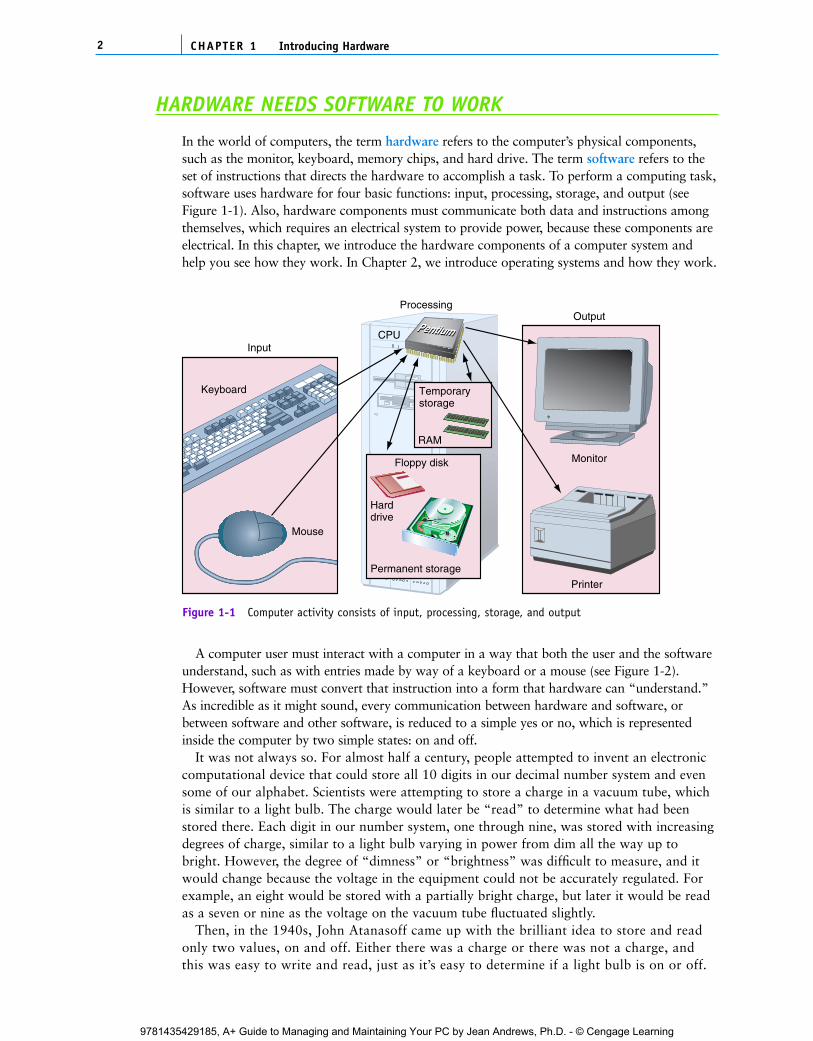
In the world of computers, the term hardware refers to the computer’s physical components,such as the monitor, keyboard, memory chips, and hard drive. The term software refers to theset of instructions that directs the hardware to accomplish a task. To perform a computing task,software uses hardware for four basic functions: input, processing, storage, and output (seeFigure 1-1). Also, hardware components must communicate both data and instructions amongthemselves, which requires an electrical system to provide power, because these components areelectrical. In this chapter, we introduce the hardware components of a computer system andhelp you see how they work. In Chapter 2, we introduce operating systems and how they work.
CHAPTER 12 Introducing Hardware
CPU
Printer
Output
Monitor
Temporarystorage
RAM
Permanent storage
Harddrive
Floppy disk
Input
Processing
Keyboard
Mouse
Figure 1-1 Computer activity consists of input, processing, storage, and output
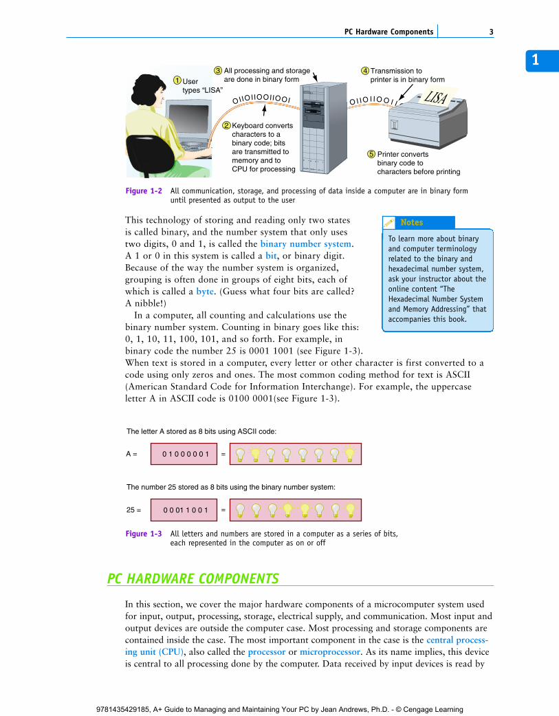
A computer user must interact with a computer in a way that both the user and the softwareunderstand, such as with entries made by way of a keyboard or a mouse (see Figure 1-2).However, software must convert that instruction into a form that hardware can “understand.”As incredible as it might sound, every communication between hardware and software, orbetween software and other software, is reduced to a simple yes or no, which is representedinside the computer by two simple states: on and off.
It was not always so. For almost half a century, people attempted to invent an electroniccomputational device that could store all 10 digits in our decimal number system and evensome of our alphabet. Scientists were attempting to store a charge in a vacuum tube, whichis similar to a light bulb. The charge would later be “read” to determine what had beenstored there. Each digit in our number system, one through nine, was stored with increasingdegrees of charge, similar to a light bulb varying in power from dim all the way up tobright. However, the degree of “dimness” or “brightness” was difficult to measure, and itwould change because the voltage in the equipment could not be accurately regulated. Forexample, an eight would be stored with a partially bright charge, but later it would be readas a seven or nine as the voltage on the vacuum tube fluctuated slightly.
Then, in the 1940s, John Atanasoff came up with the brilliant idea to store and readonly two values, on and off. Either there was a charge or there was not a charge, andthis was easy to write and read, just as it’s easy to determine if a light bulb is on or off.
C5865_01_CTP.qxd 9/22/06 5:17 PM Page 2
9781435429185, A+ Guide to Managing and Maintaining Your PC by Jean Andrews, Ph.D. - © Cengage Learning
1
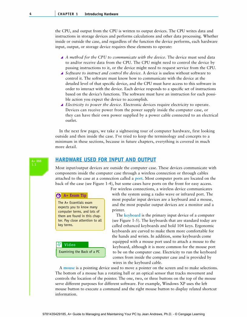
This technology of storing and reading only two statesis called binary, and the number system that only usestwo digits, 0 and 1, is called the binary number system.A 1 or 0 in this system is called a bit, or binary digit.Because of the way the number system is organized,grouping is often done in groups of eight bits, each ofwhich is called a byte. (Guess what four bits are called?A nibble!)
In a computer, all counting and calculations use thebinary number system. Counting in binary goes like this:0, 1, 10, 11, 100, 101, and so forth. For example, inbinary code the number 25 is 0001 1001 (see Figure 1-3).When text is stored in a computer, every letter or other character is first converted to acode using only zeros and ones. The most common coding method for text is ASCII(American Standard Code for Information Interchange). For example, the uppercaseletter A in ASCII code is 0100 0001(see Figure 1-3).
3PC Hardware Components
O I I O I I O O I I O
All processing and storageare done in binary form
Transmission to printer is in binary formUser
types “LISA”
OIIOIIOOIIOOI
Keyboard convertscharacters to abinary code; bitsare transmitted tomemory and toCPU for processing
Printer convertsbinary code to characters before printing
3
2
5
14
Figure 1-2 All communication, storage, and processing of data inside a computer are in binary formuntil presented as output to the user
The letter A stored as 8 bits using ASCII code:
The number 25 stored as 8 bits using the binary number system:
A =
25 =
0 1 0 0 0 0 0 1 =
0 0 01 1 0 0 1 =
Figure 1-3 All letters and numbers are stored in a computer as a series of bits,each represented in the computer as on or off
PC HARDWARE COMPONENTS
In this section, we cover the major hardware components of a microcomputer system usedfor input, output, processing, storage, electrical supply, and communication. Most input andoutput devices are outside the computer case. Most processing and storage components arecontained inside the case. The most important component in the case is the central process-ing unit (CPU), also called the processor or microprocessor. As its name implies, this deviceis central to all processing done by the computer. Data received by input devices is read by
To learn more about binaryand computer terminologyrelated to the binary andhexadecimal number system,ask your instructor about theonline content “TheHexadecimal Number Systemand Memory Addressing” thataccompanies this book.
Notes
C5865_01_CTP.qxd 9/22/06 5:17 PM Page 3
9781435429185, A+ Guide to Managing and Maintaining Your PC by Jean Andrews, Ph.D. - © Cengage Learning
the CPU, and output from the CPU is written to output devices. The CPU writes data andinstructions in storage devices and performs calculations and other data processing. Whetherinside or outside the case, and regardless of the function the device performs, each hardwareinput, output, or storage device requires these elements to operate:
A method for the CPU to communicate with the device. The device must send datato and/or receive data from the CPU. The CPU might need to control the device bypassing instructions to it, or the device might need to request service from the CPU.Software to instruct and control the device. A device is useless without software tocontrol it. The software must know how to communicate with the device at thedetailed level of that specific device, and the CPU must have access to this software inorder to interact with the device. Each device responds to a specific set of instructionsbased on the device’s functions. The software must have an instruction for each possi-ble action you expect the device to accomplish.Electricity to power the device. Electronic devices require electricity to operate.Devices can receive power from the power supply inside the computer case, orthey can have their own power supplied by a power cable connected to an electricaloutlet.
In the next few pages, we take a sightseeing tour of computer hardware, first lookingoutside and then inside the case. I’ve tried to keep the terminology and concepts to aminimum in these sections, because in future chapters, everything is covered in muchmore detail.
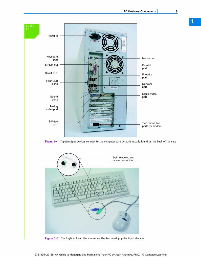
HARDWARE USED FOR INPUT AND OUTPUTMost input/output devices are outside the computer case. These devices communicate withcomponents inside the computer case through a wireless connection or through cablesattached to the case at a connection called a port. Most computer ports are located on theback of the case (see Figure 1-4), but some cases have ports on the front for easy access.
For wireless connections, a wireless device communicateswith the system using a radio wave or infrared port. Themost popular input devices are a keyboard and a mouse,and the most popular output devices are a monitor and aprinter.
The keyboard is the primary input device of a computer(see Figure 1-5). The keyboards that are standard today arecalled enhanced keyboards and hold 104 keys. Ergonomickeyboards are curved to make them more comfortable forthe hands and wrists. In addition, some keyboards comeequipped with a mouse port used to attach a mouse to thekeyboard, although it is more common for the mouse portto be on the computer case. Electricity to run the keyboardcomes from inside the computer case and is provided bywires in the keyboard cable.
A mouse is a pointing device used to move a pointer on the screen and to make selections.The bottom of a mouse has a rotating ball or an optical sensor that tracks movement andcontrols the location of the pointer. The one, two, or three buttons on the top of the mouseserve different purposes for different software. For example, Windows XP uses the leftmouse button to execute a command and the right mouse button to display related shortcutinformation.
CHAPTER 14 Introducing Hardware
A+ ESS1.1
The A+ Essentials examexpects you to know manycomputer terms, and lots ofthem are found in this chap-ter. Pay close attention to allkey terms.
A+ Exam Tip6
Examining the Back of a PC
Video 8
C5865_01_CTP.qxd 9/22/06 5:17 PM Page 4
9781435429185, A+ Guide to Managing and Maintaining Your PC by Jean Andrews, Ph.D. - © Cengage Learning
1
5PC Hardware Components
Keyboardport
S/PDIF out Parallelport
Mouse port
Four USBports
Serial port
Networkport
Analogvideo port
S-Videoport
Soundports
Power in
FireWireport
Digital videoport
Two phone lineports for modem
Figure 1-4 Input/output devices connect to the computer case by ports usually found on the back of the case
6-pin keyboard andmouse connectors
Figure 1-5 The keyboard and the mouse are the two most popular input devices
A+ ESS1.1
C5865_01_CTP.qxd 9/22/06 5:17 PM Page 5
9781435429185, A+ Guide to Managing and Maintaining Your PC by Jean Andrews, Ph.D. - © Cengage Learning
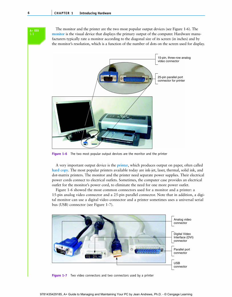
The monitor and the printer are the two most popular output devices (see Figure 1-6). Themonitor is the visual device that displays the primary output of the computer. Hardware manu-facturers typically rate a monitor according to the diagonal size of its screen (in inches) and bythe monitor’s resolution, which is a function of the number of dots on the screen used for display.
CHAPTER 16 Introducing Hardware
25-pin parallel portconnector for printer
15-pin, three-row analog video connector
Figure 1-6 The two most popular output devices are the monitor and the printer
A very important output device is the printer, which produces output on paper, often calledhard copy. The most popular printers available today are ink-jet, laser, thermal, solid ink, anddot-matrix printers. The monitor and the printer need separate power supplies. Their electricalpower cords connect to electrical outlets. Sometimes, the computer case provides an electricaloutlet for the monitor’s power cord, to eliminate the need for one more power outlet.
Figure 1-6 showed the most common connectors used for a monitor and a printer: a 15-pin analog video connector and a 25-pin parallel connector. Note that in addition, a digi-tal monitor can use a digital video connector and a printer sometimes uses a universal serialbus (USB) connector (see Figure 1-7).
Analog videoconnector
Parallel portconnector
USBconnector
Digital VideoInterface (DVI)connector
Figure 1-7 Two video connectors and two connectors used by a printer
A+ ESS1.1
C5865_01_CTP.qxd 9/22/06 5:17 PM Page 6
9781435429185, A+ Guide to Managing and Maintaining Your PC by Jean Andrews, Ph.D. - © Cengage Learning
Rear of case
Circuit boards(expansion cards)
Hard drive
Floppy drive is hiddenin this bay
Data cable
Front of case
Zip drive
CD-ROM drive
Power cords
Motherboard
Pentium II CPU
Power supply
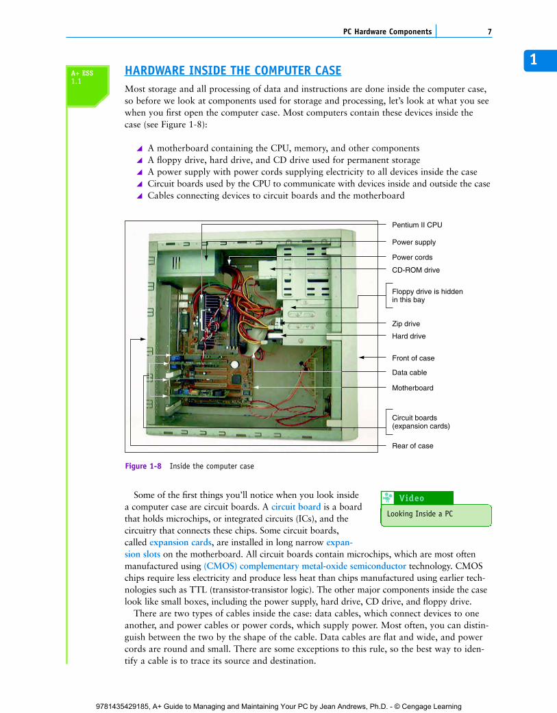
Figure 1-8 Inside the computer case
1HARDWARE INSIDE THE COMPUTER CASEMost storage and all processing of data and instructions are done inside the computer case,so before we look at components used for storage and processing, let’s look at what you seewhen you first open the computer case. Most computers contain these devices inside thecase (see Figure 1-8):
A motherboard containing the CPU, memory, and other componentsA floppy drive, hard drive, and CD drive used for permanent storageA power supply with power cords supplying electricity to all devices inside the caseCircuit boards used by the CPU to communicate with devices inside and outside the caseCables connecting devices to circuit boards and the motherboard
7PC Hardware Components
Some of the first things you’ll notice when you look insidea computer case are circuit boards. A circuit board is a boardthat holds microchips, or integrated circuits (ICs), and thecircuitry that connects these chips. Some circuit boards,called expansion cards, are installed in long narrow expan-sion slots on the motherboard. All circuit boards contain microchips, which are most oftenmanufactured using (CMOS) complementary metal-oxide semiconductor technology. CMOSchips require less electricity and produce less heat than chips manufactured using earlier tech-nologies such as TTL (transistor-transistor logic). The other major components inside the caselook like small boxes, including the power supply, hard drive, CD drive, and floppy drive.
There are two types of cables inside the case: data cables, which connect devices to oneanother, and power cables or power cords, which supply power. Most often, you can distin-guish between the two by the shape of the cable. Data cables are flat and wide, and powercords are round and small. There are some exceptions to this rule, so the best way to iden-tify a cable is to trace its source and destination.
A+ ESS1.1
Looking Inside a PC
Video 8
C5865_01_CTP.qxd 9/30/06 2:24 PM Page 7
9781435429185, A+ Guide to Managing and Maintaining Your PC by Jean Andrews, Ph.D. - © Cengage Learning
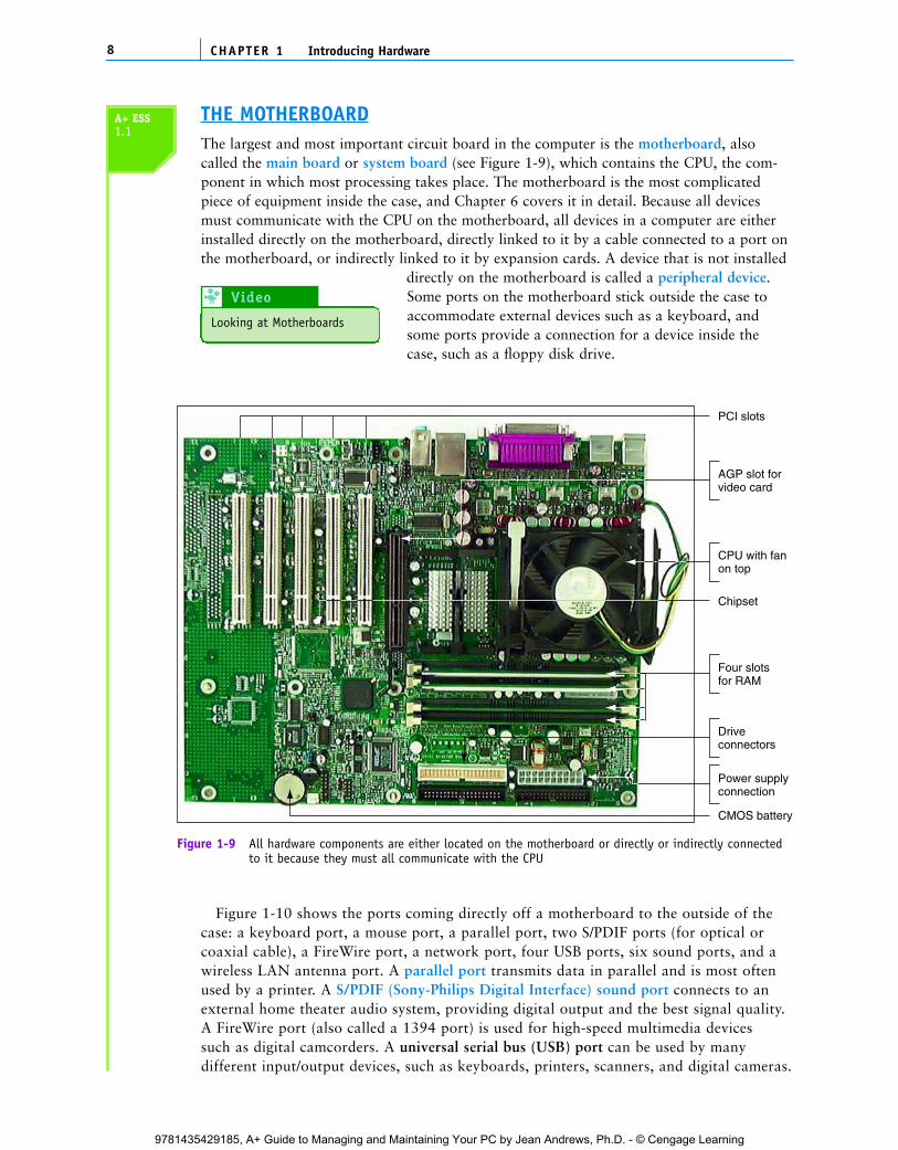
THE MOTHERBOARDThe largest and most important circuit board in the computer is the motherboard, alsocalled the main board or system board (see Figure 1-9), which contains the CPU, the com-ponent in which most processing takes place. The motherboard is the most complicatedpiece of equipment inside the case, and Chapter 6 covers it in detail. Because all devicesmust communicate with the CPU on the motherboard, all devices in a computer are eitherinstalled directly on the motherboard, directly linked to it by a cable connected to a port onthe motherboard, or indirectly linked to it by expansion cards. A device that is not installed
directly on the motherboard is called a peripheral device.Some ports on the motherboard stick outside the case toaccommodate external devices such as a keyboard, andsome ports provide a connection for a device inside thecase, such as a floppy disk drive.
CHAPTER 18 Introducing Hardware
CMOS battery
Driveconnectors
Power supplyconnection
Four slotsfor RAM
CPU with fanon top
AGP slot forvideo card
PCI slots
Chipset
Figure 1-9 All hardware components are either located on the motherboard or directly or indirectly connectedto it because they must all communicate with the CPU
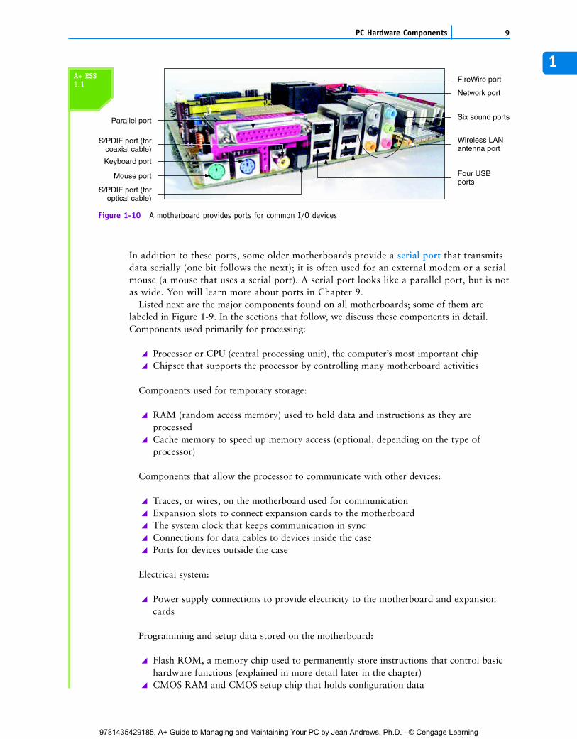
Figure 1-10 shows the ports coming directly off a motherboard to the outside of thecase: a keyboard port, a mouse port, a parallel port, two S/PDIF ports (for optical orcoaxial cable), a FireWire port, a network port, four USB ports, six sound ports, and awireless LAN antenna port. A parallel port transmits data in parallel and is most oftenused by a printer. A S/PDIF (Sony-Philips Digital Interface) sound port connects to anexternal home theater audio system, providing digital output and the best signal quality.A FireWire port (also called a 1394 port) is used for high-speed multimedia devicessuch as digital camcorders. A universal serial bus (USB) port can be used by manydifferent input/output devices, such as keyboards, printers, scanners, and digital cameras.
A+ ESS1.1
Looking at Motherboards
Video 8
C5865_01_CTP.qxd 9/22/06 5:17 PM Page 8
9781435429185, A+ Guide to Managing and Maintaining Your PC by Jean Andrews, Ph.D. - © Cengage Learning
1
In addition to these ports, some older motherboards provide a serial port that transmitsdata serially (one bit follows the next); it is often used for an external modem or a serialmouse (a mouse that uses a serial port). A serial port looks like a parallel port, but is notas wide. You will learn more about ports in Chapter 9.
Listed next are the major components found on all motherboards; some of them arelabeled in Figure 1-9. In the sections that follow, we discuss these components in detail.Components used primarily for processing:
Processor or CPU (central processing unit), the computer’s most important chipChipset that supports the processor by controlling many motherboard activities
Components used for temporary storage:
RAM (random access memory) used to hold data and instructions as they areprocessedCache memory to speed up memory access (optional, depending on the type ofprocessor)
Components that allow the processor to communicate with other devices:
Traces, or wires, on the motherboard used for communicationExpansion slots to connect expansion cards to the motherboardThe system clock that keeps communication in syncConnections for data cables to devices inside the casePorts for devices outside the case
Electrical system:
Power supply connections to provide electricity to the motherboard and expansioncards
Programming and setup data stored on the motherboard:
Flash ROM, a memory chip used to permanently store instructions that control basichardware functions (explained in more detail later in the chapter)CMOS RAM and CMOS setup chip that holds configuration data
9PC Hardware Components
Mouse port
Keyboard port
S/PDIF port (forcoaxial cable)
S/PDIF port (foroptical cable)
Four USBports
Wireless LANantenna port
Six sound ports
Network port
FireWire port
Parallel port
Figure 1-10 A motherboard provides ports for common I/O devices
A+ ESS1.1
C5865_01_CTP.qxd 9/22/06 5:17 PM Page 9
9781435429185, A+ Guide to Managing and Maintaining Your PC by Jean Andrews, Ph.D. - © Cengage Learning
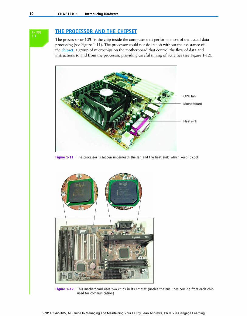
THE PROCESSOR AND THE CHIPSETThe processor or CPU is the chip inside the computer that performs most of the actual dataprocessing (see Figure 1-11). The processor could not do its job without the assistance ofthe chipset, a group of microchips on the motherboard that control the flow of data andinstructions to and from the processor, providing careful timing of activities (see Figure 1-12).
CHAPTER 110 Introducing Hardware
Motherboard
Heat sink
CPU fan
Figure 1-11 The processor is hidden underneath the fan and the heat sink, which keep it cool
Figure 1-12 This motherboard uses two chips in its chipset (notice the bus lines coming from each chipused for communication)
A+ ESS1.1
C5865_01_CTP.qxd 9/22/06 5:17 PM Page 10
9781435429185, A+ Guide to Managing and Maintaining Your PC by Jean Andrews, Ph.D. - © Cengage Learning
1In this book, we discuss various types of computers, but we focus on the most common personalcomputers (PCs), referred to as IBM-compatible. These are built around microprocessors andchipsets manufactured by Intel Corporation, AMD, VIA, SiS, Cyrix, and other manufacturers.The Macintosh family of computers, manufactured by Apple Computer, Inc., has been builtaround a family of microprocessors, the PowerPC by IBM, although Apple is currently movingtoward Intel processors. You will learn more about processors and chipsets in Chapter 5.
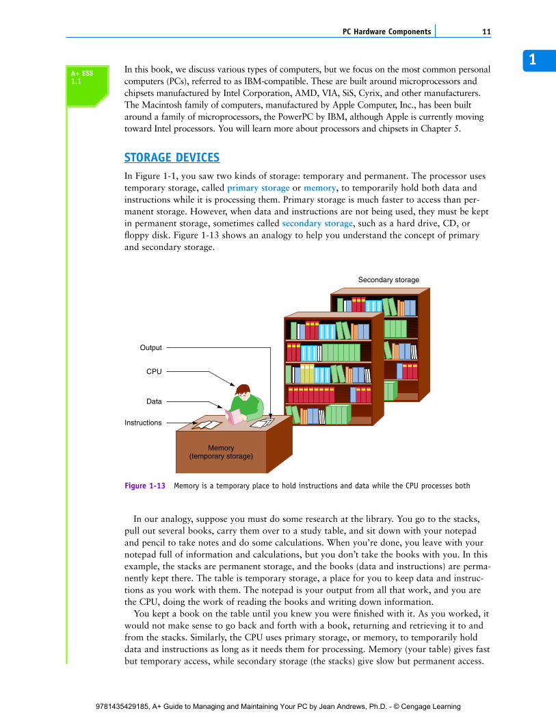
STORAGE DEVICESIn Figure 1-1, you saw two kinds of storage: temporary and permanent. The processor usestemporary storage, called primary storage or memory, to temporarily hold both data andinstructions while it is processing them. Primary storage is much faster to access than per-manent storage. However, when data and instructions are not being used, they must be keptin permanent storage, sometimes called secondary storage, such as a hard drive, CD, orfloppy disk. Figure 1-13 shows an analogy to help you understand the concept of primaryand secondary storage.
11PC Hardware Components
CPU
Data
Memory(temporary storage)
Secondary storage
Instructions
Output
Figure 1-13 Memory is a temporary place to hold instructions and data while the CPU processes both
In our analogy, suppose you must do some research at the library. You go to the stacks,pull out several books, carry them over to a study table, and sit down with your notepadand pencil to take notes and do some calculations. When you’re done, you leave with yournotepad full of information and calculations, but you don’t take the books with you. In thisexample, the stacks are permanent storage, and the books (data and instructions) are perma-nently kept there. The table is temporary storage, a place for you to keep data and instruc-tions as you work with them. The notepad is your output from all that work, and you arethe CPU, doing the work of reading the books and writing down information.
You kept a book on the table until you knew you were finished with it. As you worked, itwould not make sense to go back and forth with a book, returning and retrieving it to andfrom the stacks. Similarly, the CPU uses primary storage, or memory, to temporarily holddata and instructions as long as it needs them for processing. Memory (your table) gives fastbut temporary access, while secondary storage (the stacks) give slow but permanent access.
A+ ESS1.1
C5865_01_CTP.qxd 9/22/06 5:17 PM Page 11
9781435429185, A+ Guide to Managing and Maintaining Your PC by Jean Andrews, Ph.D. - © Cengage Learning
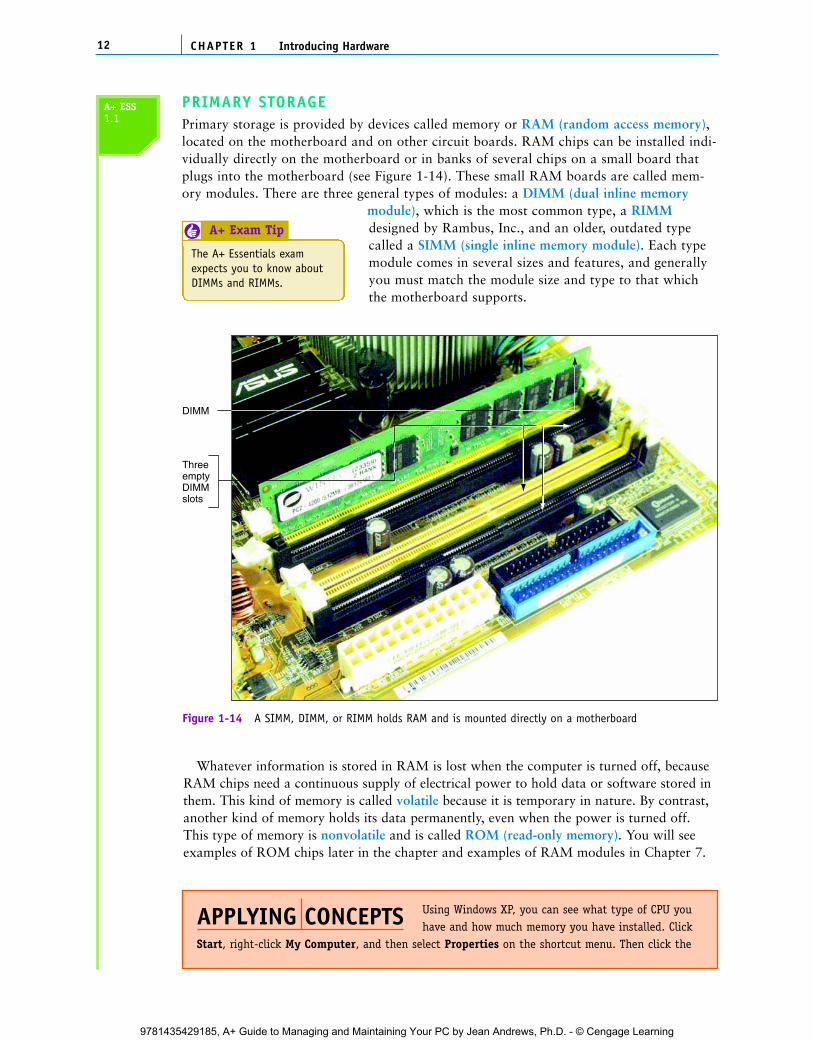
PRIMARY STORAGEPrimary storage is provided by devices called memory or RAM (random access memory),located on the motherboard and on other circuit boards. RAM chips can be installed indi-vidually directly on the motherboard or in banks of several chips on a small board thatplugs into the motherboard (see Figure 1-14). These small RAM boards are called mem-ory modules. There are three general types of modules: a DIMM (dual inline memory
module), which is the most common type, a RIMMdesigned by Rambus, Inc., and an older, outdated typecalled a SIMM (single inline memory module). Each typemodule comes in several sizes and features, and generallyyou must match the module size and type to that whichthe motherboard supports.
CHAPTER 112 Introducing Hardware
DIMM
ThreeemptyDIMMslots
Figure 1-14 A SIMM, DIMM, or RIMM holds RAM and is mounted directly on a motherboard
Whatever information is stored in RAM is lost when the computer is turned off, becauseRAM chips need a continuous supply of electrical power to hold data or software stored inthem. This kind of memory is called volatile because it is temporary in nature. By contrast,another kind of memory holds its data permanently, even when the power is turned off.This type of memory is nonvolatile and is called ROM (read-only memory). You will seeexamples of ROM chips later in the chapter and examples of RAM modules in Chapter 7.
Using Windows XP, you can see what type of CPU youhave and how much memory you have installed. Click
Start, right-click My Computer, and then select Properties on the shortcut menu. Then click the
APPLYING CONCEPTS
A+ ESS1.1
The A+ Essentials examexpects you to know aboutDIMMs and RIMMs.
A+ Exam Tip6
C5865_01_CTP.qxd 9/22/06 5:17 PM Page 12
9781435429185, A+ Guide to Managing and Maintaining Your PC by Jean Andrews, Ph.D. - © Cengage Learning
1
SECONDARY STORAGEAs you remember, the RAM on the motherboard is calledprimary storage. Primary storage temporarily holds bothdata and instructions as the CPU processes them. These dataand instructions are also permanently stored on devices suchas CDs, hard drives, and floppy disks, in locations that areremote from the CPU. Data and instructions cannot beprocessed by the CPU from this remote storage (called sec-ondary storage), but must first be copied into primary stor-age (RAM) for processing. The most important differencebetween primary and secondary storage is that secondarystorage is permanent. When you turn off your computer, the information in secondary stor-age remains intact. The most popular secondary storage devices are hard disks, CDs, DVDs,USB flash drives, and floppy disks.
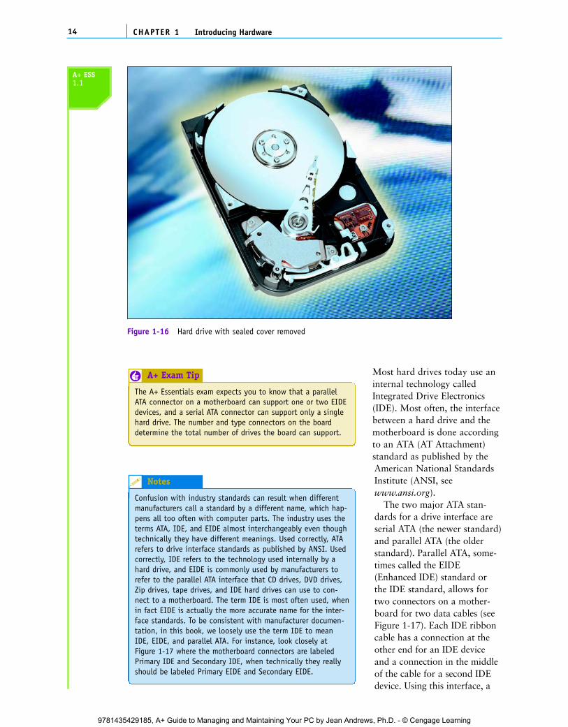
A hard drive is a sealed case containing platters or disks that rotate at a high speed(see Figure 1-16). As the platters rotate, an arm with a sensitive read/write head reachesacross the platters, both writing new data to them and reading existing data from them.
13PC Hardware Components
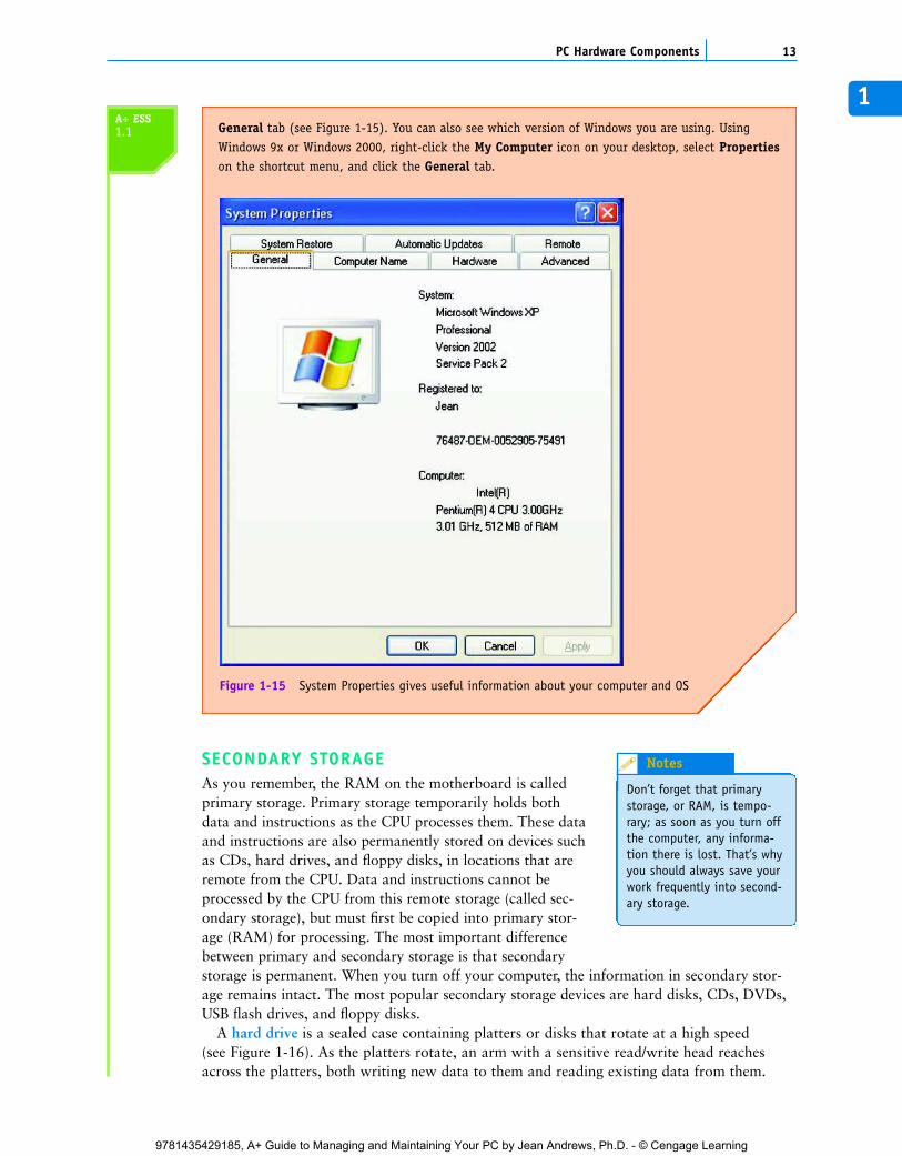
General tab (see Figure 1-15). You can also see which version of Windows you are using. UsingWindows 9x or Windows 2000, right-click the My Computer icon on your desktop, select Propertieson the shortcut menu, and click the General tab.
Figure 1-15 System Properties gives useful information about your computer and OS
A+ ESS1.1
Don’t forget that primarystorage, or RAM, is tempo-rary; as soon as you turn offthe computer, any informa-tion there is lost. That’s whyyou should always save yourwork frequently into second-ary storage.
Notes
C5865_01_CTP.qxd 9/22/06 5:17 PM Page 13
9781435429185, A+ Guide to Managing and Maintaining Your PC by Jean Andrews, Ph.D. - © Cengage Learning
Most hard drives today use aninternal technology calledIntegrated Drive Electronics(IDE). Most often, the interfacebetween a hard drive and themotherboard is done accordingto an ATA (AT Attachment)standard as published by theAmerican National StandardsInstitute (ANSI, seewww.ansi.org).
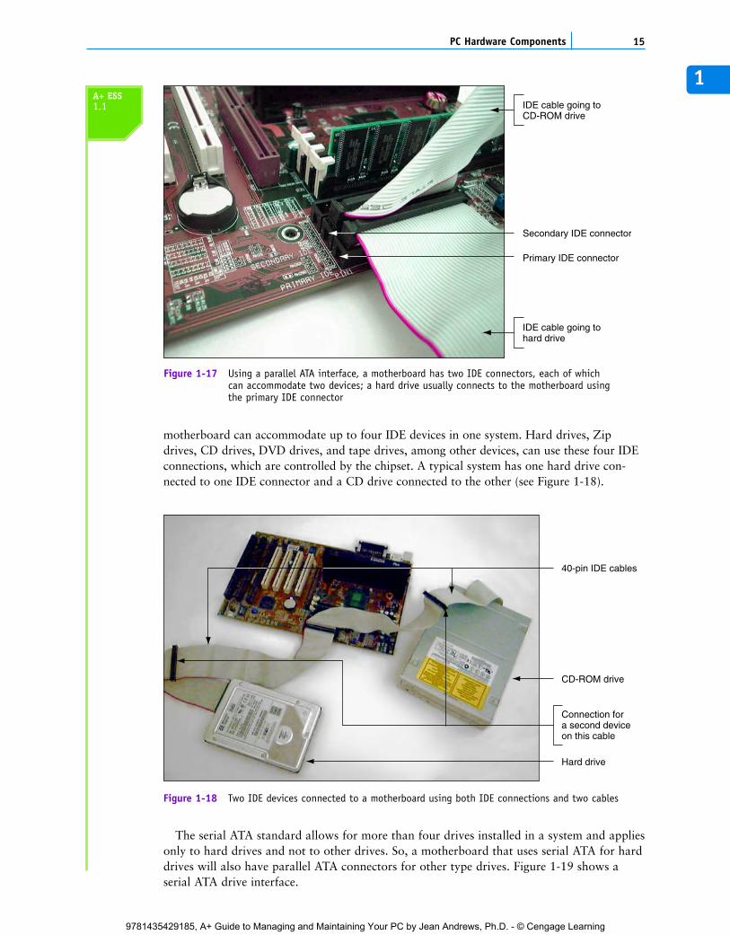
The two major ATA stan-dards for a drive interface areserial ATA (the newer standard)and parallel ATA (the olderstandard). Parallel ATA, some-times called the EIDE(Enhanced IDE) standard orthe IDE standard, allows fortwo connectors on a mother-board for two data cables (seeFigure 1-17). Each IDE ribboncable has a connection at theother end for an IDE deviceand a connection in the middleof the cable for a second IDEdevice. Using this interface, a
CHAPTER 114 Introducing Hardware
Figure 1-16 Hard drive with sealed cover removed
A+ ESS1.1
Confusion with industry standards can result when differentmanufacturers call a standard by a different name, which hap-pens all too often with computer parts. The industry uses theterms ATA, IDE, and EIDE almost interchangeably even thoughtechnically they have different meanings. Used correctly, ATArefers to drive interface standards as published by ANSI. Usedcorrectly, IDE refers to the technology used internally by ahard drive, and EIDE is commonly used by manufacturers torefer to the parallel ATA interface that CD drives, DVD drives,Zip drives, tape drives, and IDE hard drives can use to con-nect to a motherboard. The term IDE is most often used, whenin fact EIDE is actually the more accurate name for the inter-face standards. To be consistent with manufacturer documen-tation, in this book, we loosely use the term IDE to meanIDE, EIDE, and parallel ATA. For instance, look closely atFigure 1-17 where the motherboard connectors are labeledPrimary IDE and Secondary IDE, when technically they reallyshould be labeled Primary EIDE and Secondary EIDE.
Notes
The A+ Essentials exam expects you to know that a parallelATA connector on a motherboard can support one or two EIDEdevices, and a serial ATA connector can support only a singlehard drive. The number and type connectors on the boarddetermine the total number of drives the board can support.
A+ Exam Tip6
C5865_01_CTP.qxd 9/22/06 5:17 PM Page 14
9781435429185, A+ Guide to Managing and Maintaining Your PC by Jean Andrews, Ph.D. - © Cengage Learning
1
motherboard can accommodate up to four IDE devices in one system. Hard drives, Zipdrives, CD drives, DVD drives, and tape drives, among other devices, can use these four IDEconnections, which are controlled by the chipset. A typical system has one hard drive con-nected to one IDE connector and a CD drive connected to the other (see Figure 1-18).
15PC Hardware Components
Primary IDE connector
IDE cable going toCD-ROM drive
IDE cable going tohard drive
Secondary IDE connector
Figure 1-17 Using a parallel ATA interface, a motherboard has two IDE connectors, each of whichcan accommodate two devices; a hard drive usually connects to the motherboard using the primary IDE connector
40-pin IDE cables
Connection fora second deviceon this cable
CD-ROM drive
Hard drive
Figure 1-18 Two IDE devices connected to a motherboard using both IDE connections and two cables
The serial ATA standard allows for more than four drives installed in a system and appliesonly to hard drives and not to other drives. So, a motherboard that uses serial ATA for harddrives will also have parallel ATA connectors for other type drives. Figure 1-19 shows aserial ATA drive interface.
A+ ESS1.1
C5865_01_CTP.qxd 9/22/06 5:17 PM Page 15
9781435429185, A+ Guide to Managing and Maintaining Your PC by Jean Andrews, Ph.D. - © Cengage Learning
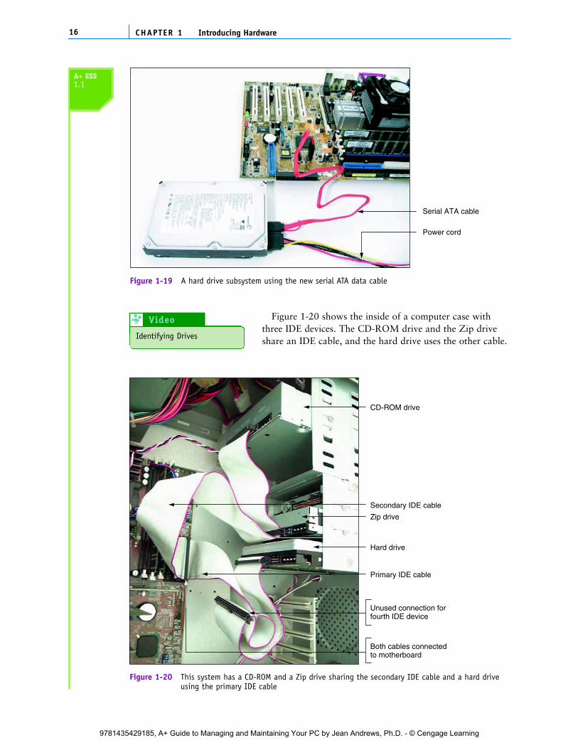
Figure 1-20 shows the inside of a computer case withthree IDE devices. The CD-ROM drive and the Zip driveshare an IDE cable, and the hard drive uses the other cable.
CHAPTER 116 Introducing Hardware
Serial ATA cable
Power cord
Figure 1-19 A hard drive subsystem using the new serial ATA data cable
CD-ROM drive
Zip drive
Hard drive
Unused connection forfourth IDE device
Primary IDE cable
Secondary IDE cable
Both cables connectedto motherboard
Figure 1-20 This system has a CD-ROM and a Zip drive sharing the secondary IDE cable and a hard driveusing the primary IDE cable
A+ ESS1.1
Identifying Drives
Video 8
C5865_01_CTP.qxd 9/22/06 5:17 PM Page 16
9781435429185, A+ Guide to Managing and Maintaining Your PC by Jean Andrews, Ph.D. - © Cengage Learning
1Both cables connect to the motherboard at the two IDE connections. (You will learn moreabout IDE, EIDE, and ATA in Chapter 8.)
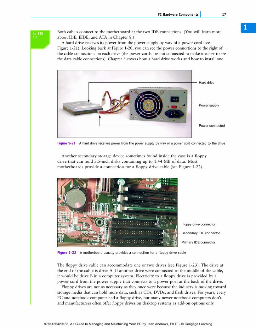
A hard drive receives its power from the power supply by way of a power cord (seeFigure 1-21). Looking back at Figure 1-20, you can see the power connections to the right ofthe cable connections on each drive (the power cords are not connected to make it easier to seethe data cable connections). Chapter 8 covers how a hard drive works and how to install one.
17PC Hardware Components
Hard drive
Power connected
Power supply
Figure 1-21 A hard drive receives power from the power supply by way of a power cord connected to the drive
Another secondary storage device sometimes found inside the case is a floppydrive that can hold 3.5-inch disks containing up to 1.44 MB of data. Mostmotherboards provide a connection for a floppy drive cable (see Figure 1-22).
Primary IDE connector
Secondary IDE connector
Floppy drive connector
Figure 1-22 A motherboard usually provides a connection for a floppy drive cable
The floppy drive cable can accommodate one or two drives (see Figure 1-23). The drive atthe end of the cable is drive A. If another drive were connected to the middle of the cable,it would be drive B in a computer system. Electricity to a floppy drive is provided by apower cord from the power supply that connects to a power port at the back of the drive.
Floppy drives are not as necessary as they once were because the industry is moving towardstorage media that can hold more data, such as CDs, DVDs, and flash drives. For years, everyPC and notebook computer had a floppy drive, but many newer notebook computers don’t,and manufacturers often offer floppy drives on desktop systems as add-on options only.
A+ ESS1.1
C5865_01_CTP.qxd 9/22/06 5:17 PM Page 17
9781435429185, A+ Guide to Managing and Maintaining Your PC by Jean Andrews, Ph.D. - © Cengage Learning
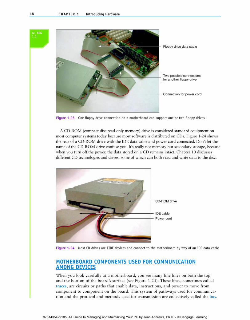
A CD-ROM (compact disc read-only memory) drive is considered standard equipment onmost computer systems today because most software is distributed on CDs. Figure 1-24 showsthe rear of a CD-ROM drive with the IDE data cable and power cord connected. Don’t let thename of the CD-ROM drive confuse you. It’s really not memory but secondary storage, becausewhen you turn off the power, the data stored on a CD remains intact. Chapter 10 discussesdifferent CD technologies and drives, some of which can both read and write data to the disc.
CHAPTER 118 Introducing Hardware
Floppy drive data cable
Connection for power cord
Two possible connectionsfor another floppy drive
Figure 1-23 One floppy drive connection on a motherboard can support one or two floppy drives
IDE cable
CD-ROM drive
Power cord
Figure 1-24 Most CD drives are EIDE devices and connect to the motherboard by way of an IDE data cable
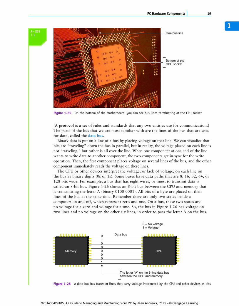
MOTHERBOARD COMPONENTS USED FOR COMMUNICATIONAMONG DEVICESWhen you look carefully at a motherboard, you see many fine lines on both the topand the bottom of the board’s surface (see Figure 1-25). These lines, sometimes calledtraces, are circuits or paths that enable data, instructions, and power to move fromcomponent to component on the board. This system of pathways used for communica-tion and the protocol and methods used for transmission are collectively called the bus.
A+ ESS1.1
C5865_01_CTP.qxd 9/22/06 5:17 PM Page 18
9781435429185, A+ Guide to Managing and Maintaining Your PC by Jean Andrews, Ph.D. - © Cengage Learning
1
(A protocol is a set of rules and standards that any two entities use for communication.)The parts of the bus that we are most familiar with are the lines of the bus that are usedfor data, called the data bus.
Binary data is put on a line of a bus by placing voltage on that line. We can visualize thatbits are “traveling” down the bus in parallel, but in reality, the voltage placed on each line isnot “traveling,” but rather is all over the line. When one component at one end of the linewants to write data to another component, the two components get in sync for the writeoperation. Then, the first component places voltage on several lines of the bus, and the othercomponent immediately reads the voltage on these lines.
The CPU or other devices interpret the voltage, or lack of voltage, on each line onthe bus as binary digits (0s or 1s). Some buses have data paths that are 8, 16, 32, 64, or128 bits wide. For example, a bus that has eight wires, or lines, to transmit data iscalled an 8-bit bus. Figure 1-26 shows an 8-bit bus between the CPU and memory thatis transmitting the letter A (binary 0100 0001). All bits of a byte are placed on theirlines of the bus at the same time. Remember there are only two states inside acomputer: on and off, which represent zero and one. On a bus, these two states areno voltage for a zero and voltage for a one. So, the bus in Figure 1-26 has voltage ontwo lines and no voltage on the other six lines, in order to pass the letter A on the bus.
19PC Hardware Components
One bus line
Bottom of theCPU socket
Figure 1-25 On the bottom of the motherboard, you can see bus lines terminating at the CPU socket
Memory CPU
01000001
Data bus
0 = No voltage1 = Voltage
The letter "A" on the 8-line data busbetween the CPU and memory
Figure 1-26 A data bus has traces or lines that carry voltage interpreted by the CPU and other devices as bits
A+ ESS1.1
C5865_01_CTP.qxd 9/22/06 5:17 PM Page 19
9781435429185, A+ Guide to Managing and Maintaining Your PC by Jean Andrews, Ph.D. - © Cengage Learning
This bus is only 8 bits wide, but most buses today are much wider: 16, 32, 64, or 128bits wide. Also, most buses today use a ninth bit for error checking. Adding a check bitfor each byte allows the component reading the data to verify that it is the same datawritten to the bus.
The width of a data bus is called the data path size. A motherboard can have more thanone bus, each using a different protocol, speed, data path size, and so on. The main bus onthe motherboard that communicates with the CPU, memory, and the chipset goes by severalnames: system bus, front side bus (FSB), memory bus, host bus, local bus, or external bus.In our discussions, we’ll use the term system bus or memory bus because they are moredescriptive, but know that motherboard ads typically use the term front side bus. The dataportion of most system buses on today’s motherboards is 64 bits wide with or without addi-tional lines for error checking.
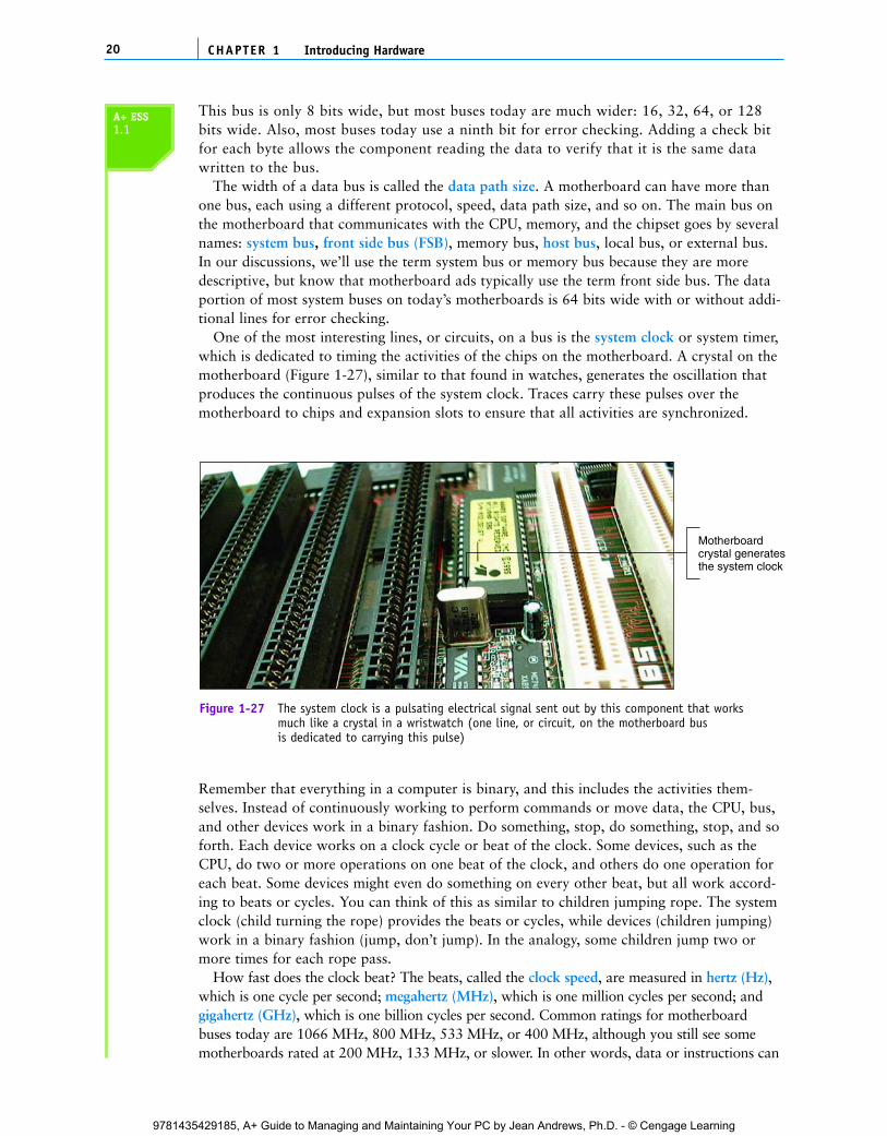
One of the most interesting lines, or circuits, on a bus is the system clock or system timer,which is dedicated to timing the activities of the chips on the motherboard. A crystal on themotherboard (Figure 1-27), similar to that found in watches, generates the oscillation thatproduces the continuous pulses of the system clock. Traces carry these pulses over themotherboard to chips and expansion slots to ensure that all activities are synchronized.
CHAPTER 120 Introducing Hardware
Motherboardcrystal generatesthe system clock
Figure 1-27 The system clock is a pulsating electrical signal sent out by this component that worksmuch like a crystal in a wristwatch (one line, or circuit, on the motherboard bus is dedicated to carrying this pulse)
Remember that everything in a computer is binary, and this includes the activities them-selves. Instead of continuously working to perform commands or move data, the CPU, bus,and other devices work in a binary fashion. Do something, stop, do something, stop, and soforth. Each device works on a clock cycle or beat of the clock. Some devices, such as theCPU, do two or more operations on one beat of the clock, and others do one operation foreach beat. Some devices might even do something on every other beat, but all work accord-ing to beats or cycles. You can think of this as similar to children jumping rope. The systemclock (child turning the rope) provides the beats or cycles, while devices (children jumping)work in a binary fashion (jump, don’t jump). In the analogy, some children jump two ormore times for each rope pass.
How fast does the clock beat? The beats, called the clock speed, are measured in hertz (Hz),which is one cycle per second; megahertz (MHz), which is one million cycles per second; andgigahertz (GHz), which is one billion cycles per second. Common ratings for motherboardbuses today are 1066 MHz, 800 MHz, 533 MHz, or 400 MHz, although you still see somemotherboards rated at 200 MHz, 133 MHz, or slower. In other words, data or instructions can
A+ ESS1.1
C5865_01_CTP.qxd 9/22/06 5:17 PM Page 20
9781435429185, A+ Guide to Managing and Maintaining Your PC by Jean Andrews, Ph.D. - © Cengage Learning

1be put on the system bus at therate of 800 million every second.A CPU operates from 166 MHzto almost 4 GHz. In otherwords, the CPU can put data orinstructions on its internal bus atthis much higher rate. Althoughwe often refer to the speed ofthe CPU and the motherboardbus, talking about the frequencyof these devices is more accurate, because the term “speed” implies a continuous flow, while theterm “frequency” implies a digital or binary flow: on and off, on and off.
The lines of a bus, including data, instruction, and power lines, often extend to the expan-sion slots (see Figure 1-28). The size and shape of an expansion slot depend on the kind ofbus it uses. Therefore, one way to determine the kind of bus you have is to examine theexpansion slots on the motherboard.
21PC Hardware Components
PCI slot
Pins on connector edgeof expansion card
Bus lines
Figure 1-28 The lines of a bus terminate at an expansion slot where they connect to pinsthat connect to lines on the expansion card inserted in the slot
Figure 1-29 shows an older motherboard with three types of expansion slots, and Figure 1-30 shows a newer motherboard that also has three types of expansion slots. Thetypes of slots shown on both boards include:
PCI (Peripheral Component Interconnect) expansion slot used for input/output devicesPCI Express slots that come in several lengths and are used by high-speed input/outputdevicesAGP (Accelerated Graphics Port) expansion slot used for a video cardISA (Industry Standard Architecture) expansion slot is outdated and seldom seen today
Notice in Figures 1-29 and 1-30 the white PCI slots are used on both the older and newerboards. A motherboard will have one slot intended for use by a video card. The older board usesan AGP slot for that purpose, and the newer board uses a long PCI Express x16 slot for video.
A+ ESS1.1
Motherboard buses are most often measured in frequenciessuch as 800 MHz, but sometimes you see a motherboard busmeasured in performance such as the A8V motherboard byAsus built to support a high-end AMD processor (seewww.asus.com and www.amd.com). This motherboard bus israted at 2000 MT/s. One MT/s is one megatransfer per secondor one million bytes per second transferred over the bus.
Notes
C5865_01_CTP.qxd 9/22/06 5:17 PM Page 21
9781435429185, A+ Guide to Managing and Maintaining Your PC by Jean Andrews, Ph.D. - © Cengage Learning
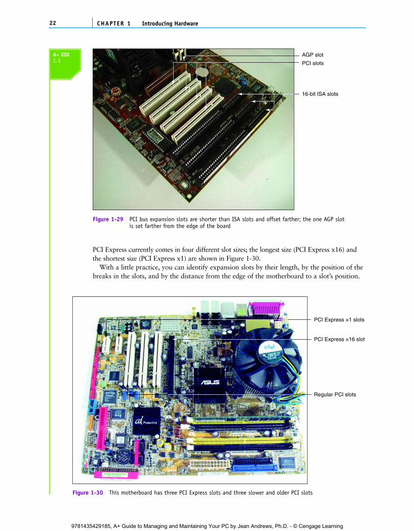
PCI Express currently comes in four different slot sizes; the longest size (PCI Express x16) andthe shortest size (PCI Express x1) are shown in Figure 1-30.
With a little practice, you can identify expansion slots by their length, by the position of thebreaks in the slots, and by the distance from the edge of the motherboard to a slot’s position.
CHAPTER 122 Introducing Hardware
PCI slots
16-bit ISA slots
AGP slot
Figure 1-29 PCI bus expansion slots are shorter than ISA slots and offset farther; the one AGP slotis set farther from the edge of the board
PCI Express ×1 slots
PCI Express ×16 slot
Regular PCI slots
Figure 1-30 This motherboard has three PCI Express slots and three slower and older PCI slots
A+ ESS1.1
C5865_01_CTP.qxd 9/22/06 5:18 PM Page 22
9781435429185, A+ Guide to Managing and Maintaining Your PC by Jean Andrews, Ph.D. - © Cengage Learning
1In Chapter 6, you’ll learn that each expansion slot communicates with the CPU by way of
its own bus. There can be a PCI Express bus, a PCI bus, an AGP bus, and, for older sys-tems, an ISA bus, each running at different speeds and providing different features toaccommodate the expansion cards that use these different slots. But all these buses connectto the main bus or system bus, which connects to the CPU.
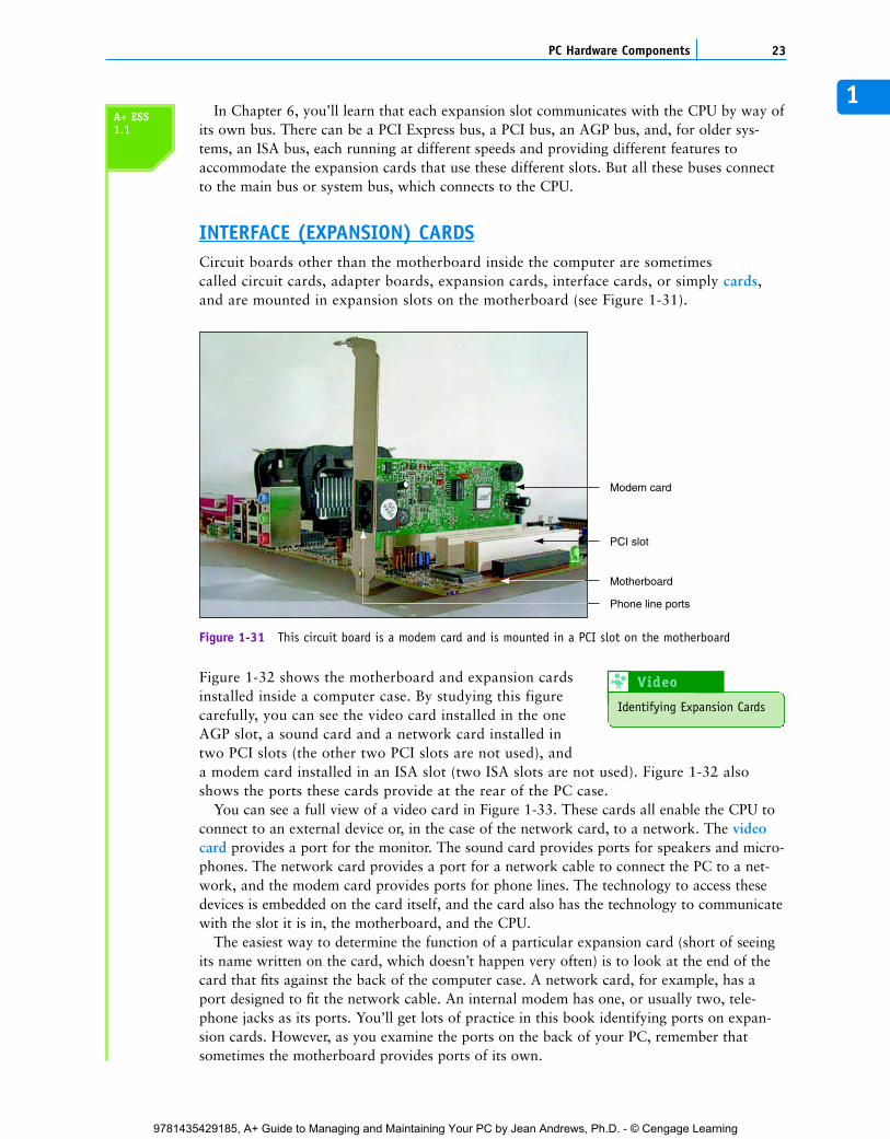
INTERFACE (EXPANSION) CARDSCircuit boards other than the motherboard inside the computer are sometimes called circuit cards, adapter boards, expansion cards, interface cards, or simply cards,and are mounted in expansion slots on the motherboard (see Figure 1-31).
23PC Hardware Components
Modem card
PCI slot
Motherboard
Phone line ports
Figure 1-31 This circuit board is a modem card and is mounted in a PCI slot on the motherboard
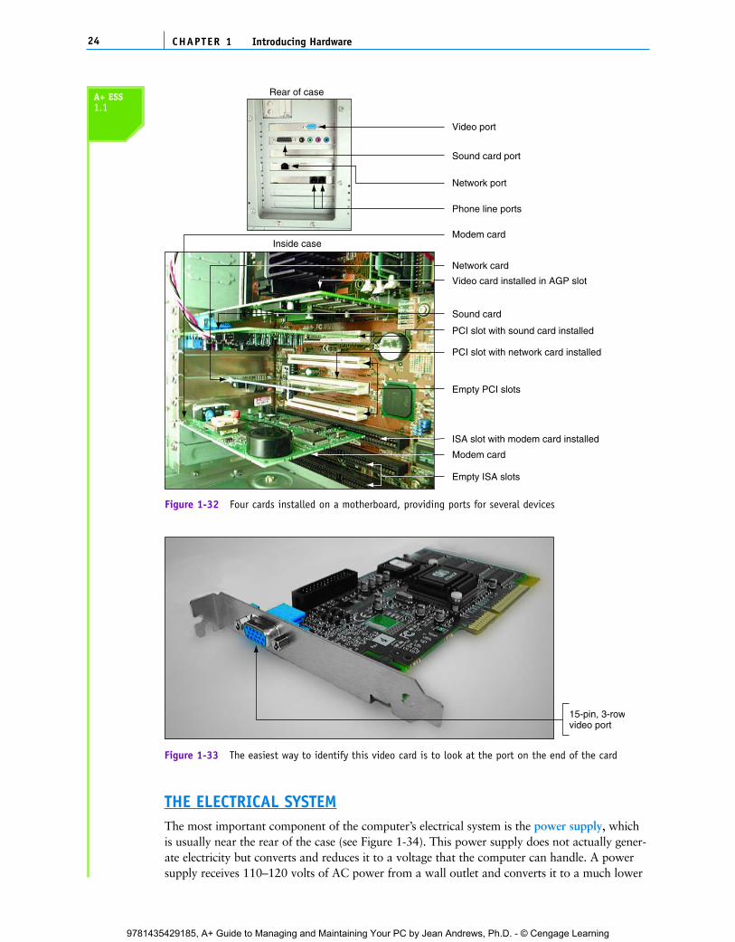
Figure 1-32 shows the motherboard and expansion cardsinstalled inside a computer case. By studying this figurecarefully, you can see the video card installed in the oneAGP slot, a sound card and a network card installed intwo PCI slots (the other two PCI slots are not used), anda modem card installed in an ISA slot (two ISA slots are not used). Figure 1-32 alsoshows the ports these cards provide at the rear of the PC case.
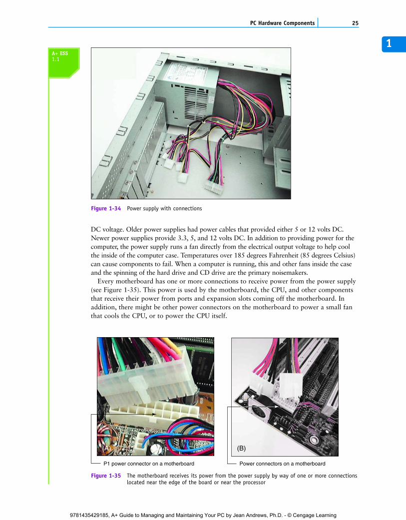
You can see a full view of a video card in Figure 1-33. These cards all enable the CPU toconnect to an external device or, in the case of the network card, to a network. The videocard provides a port for the monitor. The sound card provides ports for speakers and micro-phones. The network card provides a port for a network cable to connect the PC to a net-work, and the modem card provides ports for phone lines. The technology to access thesedevices is embedded on the card itself, and the card also has the technology to communicatewith the slot it is in, the motherboard, and the CPU.
The easiest way to determine the function of a particular expansion card (short of seeingits name written on the card, which doesn’t happen very often) is to look at the end of thecard that fits against the back of the computer case. A network card, for example, has aport designed to fit the network cable. An internal modem has one, or usually two, tele-phone jacks as its ports. You’ll get lots of practice in this book identifying ports on expan-sion cards. However, as you examine the ports on the back of your PC, remember thatsometimes the motherboard provides ports of its own.
A+ ESS1.1
Identifying Expansion Cards
Video 8
C5865_01_CTP.qxd 9/22/06 5:18 PM Page 23
9781435429185, A+ Guide to Managing and Maintaining Your PC by Jean Andrews, Ph.D. - © Cengage Learning
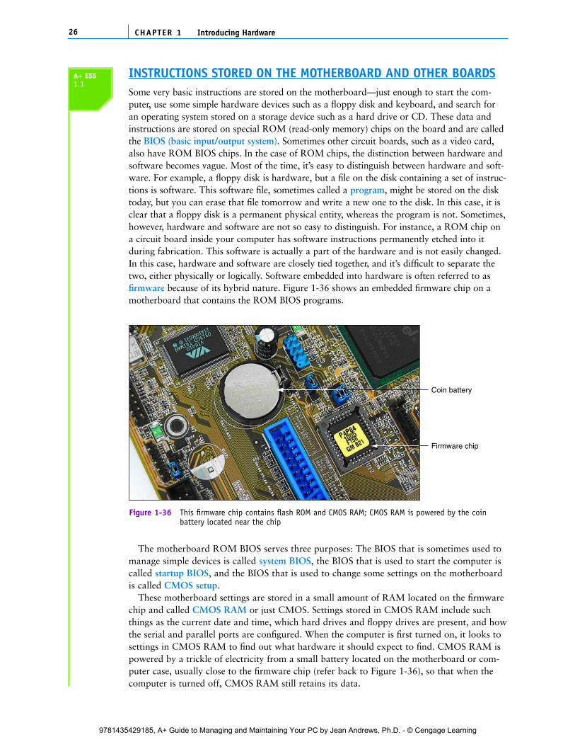
THE ELECTRICAL SYSTEMThe most important component of the computer’s electrical system is the power supply, whichis usually near the rear of the case (see Figure 1-34). This power supply does not actually gener-ate electricity but converts and reduces it to a voltage that the computer can handle. A powersupply receives 110–120 volts of AC power from a wall outlet and converts it to a much lower
CHAPTER 124 Introducing Hardware
Video card installed in AGP slot
Inside case
Empty PCI slots
PCI slot with sound card installed
Network card
Modem card
Empty ISA slots
ISA slot with modem card installed
PCI slot with network card installed
Video port
Sound card port
Network port
Phone line ports
Sound card
Rear of case
Modem card
Figure 1-32 Four cards installed on a motherboard, providing ports for several devices
15-pin, 3-rowvideo port
Figure 1-33 The easiest way to identify this video card is to look at the port on the end of the card
A+ ESS1.1
C5865_01_CTP.qxd 9/22/06 5:18 PM Page 24
9781435429185, A+ Guide to Managing and Maintaining Your PC by Jean Andrews, Ph.D. - © Cengage Learning
1
DC voltage. Older power supplies had power cables that provided either 5 or 12 volts DC.Newer power supplies provide 3.3, 5, and 12 volts DC. In addition to providing power for thecomputer, the power supply runs a fan directly from the electrical output voltage to help coolthe inside of the computer case. Temperatures over 185 degrees Fahrenheit (85 degrees Celsius)can cause components to fail. When a computer is running, this and other fans inside the caseand the spinning of the hard drive and CD drive are the primary noisemakers.
Every motherboard has one or more connections to receive power from the power supply(see Figure 1-35). This power is used by the motherboard, the CPU, and other componentsthat receive their power from ports and expansion slots coming off the motherboard. Inaddition, there might be other power connectors on the motherboard to power a small fanthat cools the CPU, or to power the CPU itself.
25PC Hardware Components
Figure 1-34 Power supply with connections
(A)
Power connectors on a motherboardP1 power connector on a motherboard
(B)
Figure 1-35 The motherboard receives its power from the power supply by way of one or more connectionslocated near the edge of the board or near the processor
A+ ESS1.1
C5865_01_CTP.qxd 9/22/06 5:18 PM Page 25
9781435429185, A+ Guide to Managing and Maintaining Your PC by Jean Andrews, Ph.D. - © Cengage Learning
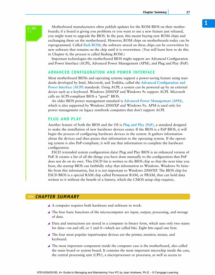
INSTRUCTIONS STORED ON THE MOTHERBOARD AND OTHER BOARDSSome very basic instructions are stored on the motherboard—just enough to start the com-puter, use some simple hardware devices such as a floppy disk and keyboard, and search foran operating system stored on a storage device such as a hard drive or CD. These data andinstructions are stored on special ROM (read-only memory) chips on the board and are calledthe BIOS (basic input/output system). Sometimes other circuit boards, such as a video card,also have ROM BIOS chips. In the case of ROM chips, the distinction between hardware andsoftware becomes vague. Most of the time, it’s easy to distinguish between hardware and soft-ware. For example, a floppy disk is hardware, but a file on the disk containing a set of instruc-tions is software. This software file, sometimes called a program, might be stored on the disktoday, but you can erase that file tomorrow and write a new one to the disk. In this case, it isclear that a floppy disk is a permanent physical entity, whereas the program is not. Sometimes,however, hardware and software are not so easy to distinguish. For instance, a ROM chip ona circuit board inside your computer has software instructions permanently etched into itduring fabrication. This software is actually a part of the hardware and is not easily changed.In this case, hardware and software are closely tied together, and it’s difficult to separate thetwo, either physically or logically. Software embedded into hardware is often referred to asfirmware because of its hybrid nature. Figure 1-36 shows an embedded firmware chip on amotherboard that contains the ROM BIOS programs.
CHAPTER 126 Introducing Hardware
Coin battery
Firmware chip
Figure 1-36 This firmware chip contains flash ROM and CMOS RAM; CMOS RAM is powered by the coinbattery located near the chip
The motherboard ROM BIOS serves three purposes: The BIOS that is sometimes used tomanage simple devices is called system BIOS, the BIOS that is used to start the computer iscalled startup BIOS, and the BIOS that is used to change some settings on the motherboardis called CMOS setup.
These motherboard settings are stored in a small amount of RAM located on the firmwarechip and called CMOS RAM or just CMOS. Settings stored in CMOS RAM include suchthings as the current date and time, which hard drives and floppy drives are present, and howthe serial and parallel ports are configured. When the computer is first turned on, it looks tosettings in CMOS RAM to find out what hardware it should expect to find. CMOS RAM ispowered by a trickle of electricity from a small battery located on the motherboard or com-puter case, usually close to the firmware chip (refer back to Figure 1-36), so that when thecomputer is turned off, CMOS RAM still retains its data.
A+ ESS1.1
C5865_01_CTP.qxd 9/22/06 5:18 PM Page 26
9781435429185, A+ Guide to Managing and Maintaining Your PC by Jean Andrews, Ph.D. - © Cengage Learning
1Motherboard manufacturers often publish updates for the ROM BIOS on their mother-
boards; if a board is giving you problems or you want to use a new feature just released,you might want to upgrade the BIOS. In the past, this meant buying new ROM chips andexchanging them on the motherboard. However, ROM chips on motherboards today can bereprogrammed. Called flash ROM, the software stored on these chips can be overwritten bynew software that remains on the chip until it is overwritten. (You will learn how to do thisin Chapter 6; the process is called flashing ROM.)
Important technologies the motherboard BIOS might support are Advanced Configurationand Power Interface (ACPI), Advanced Power Management (APM), and Plug and Play (PnP).
ADVANCED CONFIGURATION AND POWER INTERFACEMost motherboard BIOSs and operating systems support a power-saving feature using stan-dards developed by Intel, Microsoft, and Toshiba, called the Advanced Configuration andPower Interface (ACPI) standards. Using ACPI, a system can be powered up by an externaldevice such as a keyboard. Windows 2000/XP and Windows 9x support ACPI. Microsoftcalls an ACPI-compliant BIOS a “good” BIOS.
An older BIOS power management standard is Advanced Power Management (APM),which is also supported by Windows 2000/XP and Windows 9x. APM is used only forpower management on legacy notebook computers that don’t support ACPI.
PLUG AND PLAYAnother feature of both the BIOS and the OS is Plug and Play (PnP), a standard designedto make the installation of new hardware devices easier. If the BIOS is a PnP BIOS, it willbegin the process of configuring hardware devices in the system. It gathers informationabout the devices and then passes that information to the operating system. If the operat-ing system is also PnP-compliant, it will use that information to complete the hardwareconfiguration.
ESCD (extended system configuration data) Plug and Play BIOS is an enhanced version ofPnP. It creates a list of all the things you have done manually to the configuration that PnPdoes not do on its own. This ESCD list is written to the BIOS chip so that the next time youboot, the startup BIOS can faithfully relay that information to Windows. Windows 9x bene-fits from this information, but it is not important to Windows 2000/XP. The BIOS chip forESCD BIOS is a special RAM chip called Permanent RAM, or PRAM, that can hold datawritten to it without the benefit of a battery, which the CMOS setup chip requires.
27Chapter Summary
>> CHAPTER SUMMARY
A computer requires both hardware and software to work.
The four basic functions of the microcomputer are input, output, processing, and storageof data.
Data and instructions are stored in a computer in binary form, which uses only two statesfor data—on and off, or 1 and 0—which are called bits. Eight bits equal one byte.
The four most popular input/output devices are the printer, monitor, mouse, andkeyboard.
The most important component inside the computer case is the motherboard, also calledthe main board or system board. It contains the most important microchip inside the case,the central processing unit (CPU), a microprocessor or processor, as well as access to
A+ ESS1.1
C5865_01_CTP.qxd 9/22/06 5:18 PM Page 27
9781435429185, A+ Guide to Managing and Maintaining Your PC by Jean Andrews, Ph.D. - © Cengage Learning
other circuit boards and peripheral devices. All communications between the CPU andother devices must pass through the motherboard.
A ROM BIOS or firmware microchip is a hybrid of hardware and software containingprogramming embedded into the chip.
Most microchips are manufactured using CMOS (complementary metal-oxide semicon-ductor) technology.
Each hardware device needs a method to communicate with the CPU, software to controlit, and electricity to power it.
Devices outside the computer case connect to the motherboard through ports on the case.Common ports are network, FireWire, sound, serial, parallel, USB, game, keyboard, andmouse ports.
A circuit board inserted in an expansion slot on the motherboard can provide an inter-face between the motherboard and a peripheral device, or can itself be a peripheral.(An example is an internal modem.)
The chipset on a motherboard controls most activities on the motherboard and includesseveral device controllers, including the USB controller, memory controller, IDE controller,and so forth.
Primary storage, called memory or RAM, is temporary storage the CPU uses to hold dataand instructions while it is processing both.
RAM is stored on single chips, SIMMs, DIMMs, and RIMMs.
Secondary storage is slower than primary storage, but it is permanent storage. Someexamples of secondary storage devices are hard drives, CD drives, DVD drives, flashdrives, Zip drives, and floppy drives.
Most hard drives, CD drives, and DVD drives use an ATA interface standard commonlycalled EIDE (Enhanced Integrated Drive Electronics) technology, which can accommodateup to four EIDE or IDE devices on one system. Newer hard drives are the serial ATAinterface standard.
The system clock is used to synchronize activity on the motherboard. The clock sends con-tinuous pulses over the bus that different components use to control the pace of activity.
A motherboard can have several buses, including the system bus, the PCI Express bus, thePCI bus, the AGP bus, and the outdated ISA bus.
The frequency of activity on a motherboard is measured in megahertz (MHz), or one millioncycles per second. The processor operates at a much higher frequency than other componentsin the system, and its activity is measured in gigahertz (GHz), or one billion cycles per second.
The power supply inside the computer case supplies electricity to components both insideand outside the case. Some components external to the case get power from their ownelectrical cables.
ROM BIOS on a motherboard holds the basic software needed to start a PC and beginthe process of loading an operating system. Most ROM chips are flash ROM, meaningthat these programs can be updated without exchanging the chip.
The CMOS setup program is part of ROM BIOS stored on the firmware chip. This pro-gram is used to change motherboard settings or configuration information. When powerto the PC is turned off, a battery on the motherboard supplies power to CMOS RAMthat holds these settings.
CHAPTER 128 Introducing Hardware
C5865_01_CTP.qxd 9/22/06 5:18 PM Page 28
9781435429185, A+ Guide to Managing and Maintaining Your PC by Jean Andrews, Ph.D. - © Cengage Learning
1
1. Why is all data stored in a computer in binary form?
2. What are the four primary functions of hardware?
3. What are the two main input devices and two main output devices?
4. What three things do electronic hardware devices need in order to function?
5. How many bits are in a byte?
6. What is the purpose of an expansion slot on a motherboard?
7. Which component on the motherboard is used primarily for processing?
8. Name three CPU manufacturers.
9. What technology is most often used today to manufacture microchips?
10. What are two other names for the system bus?
11. What are two other names for the motherboard?
12. What are the two basic types of cables found inside a computer case and what are theirbasic functions?
13. List three types of ports that are often found coming directly off the motherboard to beused by external devices.
14. What is the purpose of the S/PDIF port?
15. List three kinds of memory modules.
29Reviewing the Basics
>> KEY TERMS
Advanced Configuration andPower Interface (ACPI)
Advanced Power Management(APM)
binary number systemBIOS (basic input/output system)bitbusbytecardscentral processing unit (CPU)chipsetcircuit boardclock speedCMOS (complementary metal-
oxide semiconductor)CMOS RAMCMOS setupdata busdata path sizeDIMM (dual inline memory
module)expansion cardsexpansion slots
firmwareflash ROMfront side bus (FSB)gigahertz (GHz)hard copyhard drivehardwarehertz (Hz)host buskeyboardmain boardmegahertz (MHz)memorymicroprocessormonitormotherboardmousenonvolatileparallel portperipheral devicePlug and Play (PnP)portpower supplyprimary storage
printerprocessorprogramprotocolRAM (random access memory)RIMMROM (read-only memory)S/PDIF (Sony-Philips Digital
Interface) sound portsecondary storageserial portSIMM (single inline memory
module)softwarestartup BIOSsystem BIOSsystem boardsystem bussystem clocktracesUSB (universal serial bus) portvideo cardvolatile
For explanations of key terms, see the Glossary near the end of the book.
>> REVIEWING THE BASICS
C5865_01_CTP.qxd 9/22/06 5:18 PM Page 29
9781435429185, A+ Guide to Managing and Maintaining Your PC by Jean Andrews, Ph.D. - © Cengage Learning
16. What is the difference between volatile and nonvolatile memory?
17. Of the two types of storage in a system, which type is generally faster and holds data andinstructions while the data is being processed? Which type of storage is generally slower,but more permanent?
18. What technology standard provides for up to four devices on a system, including the harddrive as one of those devices? What are two common industry names loosely used todescribe this standard?
19. What is the size of the data path on most system buses today?
20. What is the measurement of frequency of a system bus and CPU? Which is faster, the sys-tem bus or the CPU?
21. Name four types of buses that might be on a motherboard today.
22. A power supply receives 120 volts of _____ power from a wall outlet and converts it to3.3, 5, and 12 volts of _____ power.
23. ROM BIOS or firmware chips that can be upgraded without replacing the chips arecalled _____.
24. CMOS setup allows a technician to change configuration settings on a motherboard storedin _____.
25. Name three examples of secondary storage devices.
26. A hertz is _____ cycles per second; a megahertz is _____ cycles per second, and a gigahertzis _____ cycles per second.
27. An AGP slot is normally used for a(n) _____ expansion card.
28. How many sizes of PCI Express slots are currently manufactured for personal computers?
29. Name the three purposes the motherboard ROM BIOS serves.
30. From where does CMOS RAM receive its power?
CHAPTER 130 Introducing Hardware
>> THINKING CRITICALLY
1. When selecting secondary storage devices for a new desktop PC, which is more important,a CD-ROM drive or a floppy drive? Why?
2. Based on what you have learned in this chapter, when working on a Microsoft Word docu-ment, why is it important to save your work often? Explain your answer using the twoterms, primary storage and secondary storage.
3. Most buses are 16, 32, 64, or 128 bits wide. Why do you think these bus widths are multi-ples of eight?
4. Why would it be difficult to install four hard drives, one CD-ROM drive, and one DVDdrive in a single low-end system?
5. In this chapter, a light bulb is used to demonstrate the binary concept used for computerstorage and communication. Give another example in everyday life to explain this binaryconcept. Get creative.
6. If the CMOS battery inside your computer system died, when you first turn on yoursystem, will you expect the system to boot up normally to the operating system level?
C5865_01_CTP.qxd 9/22/06 5:18 PM Page 30
9781435429185, A+ Guide to Managing and Maintaining Your PC by Jean Andrews, Ph.D. - © Cengage Learning
1What information do you think the system would not have available for a successfulboot?
7. Why is it more accurate to describe the CPU and motherboard bus using the termfrequency rather than speed? Explain your answer.
31Hands-On Projects
>> HANDS-ON PROJECTS
PROJECT 1-1: Identifying Ports on Your Computer
Look at the back of your home or lab computer and make a diagram showing the ports.Label all the ports in the diagram and note which ones are used and which ones are not used.
PROJECT 1-2: Researching on the Internet
The Internet is an incredibly rich source of information about computer hardware and soft-ware. Answer these questions, using the Internet as your source:
1. What is the frequency of the fastest CPU for a desktop computer that you can find adver-tised on the Web? Print the Web page showing the CPU and its frequency.
2. Print a Web page advertising a motherboard. What is the frequency of the system bus?What is the system bus called?
3. Print a Web page advertising computer memory. How much RAM is on one module?
4. Print the Web page of any hardware device that uses a USB port.
PROJECT 1-3: Identifying Motherboard Components
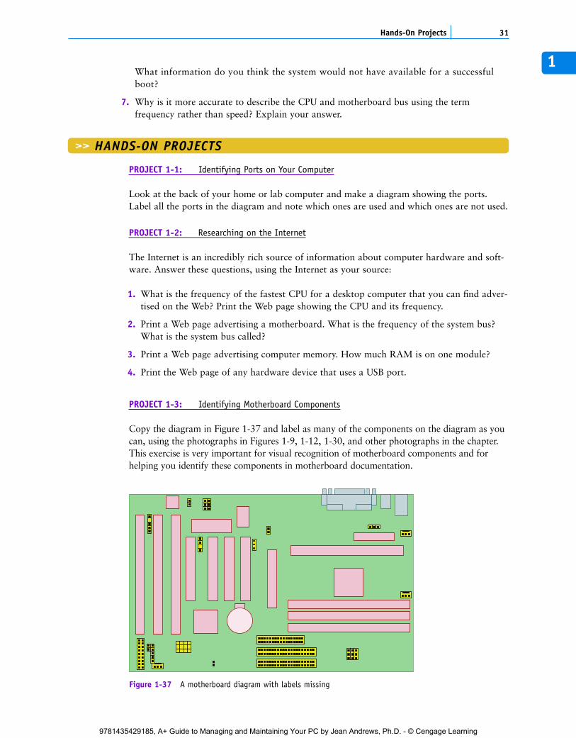
Copy the diagram in Figure 1-37 and label as many of the components on the diagram as youcan, using the photographs in Figures 1-9, 1-12, 1-30, and other photographs in the chapter.This exercise is very important for visual recognition of motherboard components and forhelping you identify these components in motherboard documentation.
Figure 1-37 A motherboard diagram with labels missing
C5865_01_CTP.qxd 9/22/06 5:18 PM Page 31
9781435429185, A+ Guide to Managing and Maintaining Your PC by Jean Andrews, Ph.D. - © Cengage Learning
PROJECT 1-4: Examining Your Computer
What type of CPU does your computer have, and howmuch memory is installed? To answer these questions, usingWindows XP, click Start, right-click My Computer, andselect Properties on the shortcut menu. The SystemProperties dialog box opens. Click the General tab. (UsingWindows 2000 or Windows 98, right-click the MyComputer icon on your desktop and select Properties onthe shortcut menu.) The CPU information is listed in thisdialog box. Print a screen shot of this dialog box. Onequick and easy way to get a hard copy of a screen is to usePaint. Follow these directions to print the screen:
1. Press the PrintScrn (print screen) key. This puts thescreen capture on your Windows Clipboard.
2. Open Paint. Click Start, All Programs, Accessories, Paint.
3. Click Edit, Paste to put the contents of the Clipboard into Paint. If necessary, click Yes tothe dialog box that pops up to confirm the paste.
4. To print the page, click File, Print.
PROJECT 1-5: Learning to Think in Binary and Hex
Use the online content, “The Hexadecimal Number System and Memory Addressing” and“ASCII Character Set and Ansi.sys” that accompanies this book to answer these questions:
1. What is the ASCII code in binary and in decimal for a lowercase z?
2. What is the ASCII code in binary and in decimal for a period?
3. Write the binary numbers from 1 to 20.
4. What is the largest decimal number that can be stored using 8 bits, or 1 byte?
5. Write the hex numbers from 1 to 20.
6. Convert 43 to binary. Convert 43 to hex.
7. What is 1101 1001 in decimal? In hex?
CHAPTER 132 Introducing Hardware
>> REAL PROBLEMS, REAL SOLUTIONS
REAL PROBLEM 1-1: Reading a Technical Ad for a Computer System
Computer ads can sometimes be difficult to read, especially those targeting tech-savvycomputer buyers. Figure 1-38 shows an advertisement published by GIM Computer Corp(www.gimcomputers.com), a computer parts store that assembles systems from parts andsells them as a single unit price with a one-year warranty on all parts. Answer the followingquestions about this ad:
1. What is the system bus called? What two system bus frequencies are offered?
2. In the ad, what do you think P4 means?
You can capture just theactive window, instead of theentire screen, by pressingAlt+PrintScrn instead ofPrintScrn.
Notes
The A+ Essentials examexpects you to be able torecognize components on amotherboard diagram similarto the one in Figure 1-37.
A+ Exam Tip6
C5865_01_CTP.qxd 9/22/06 5:18 PM Page 32
9781435429185, A+ Guide to Managing and Maintaining Your PC by Jean Andrews, Ph.D. - © Cengage Learning
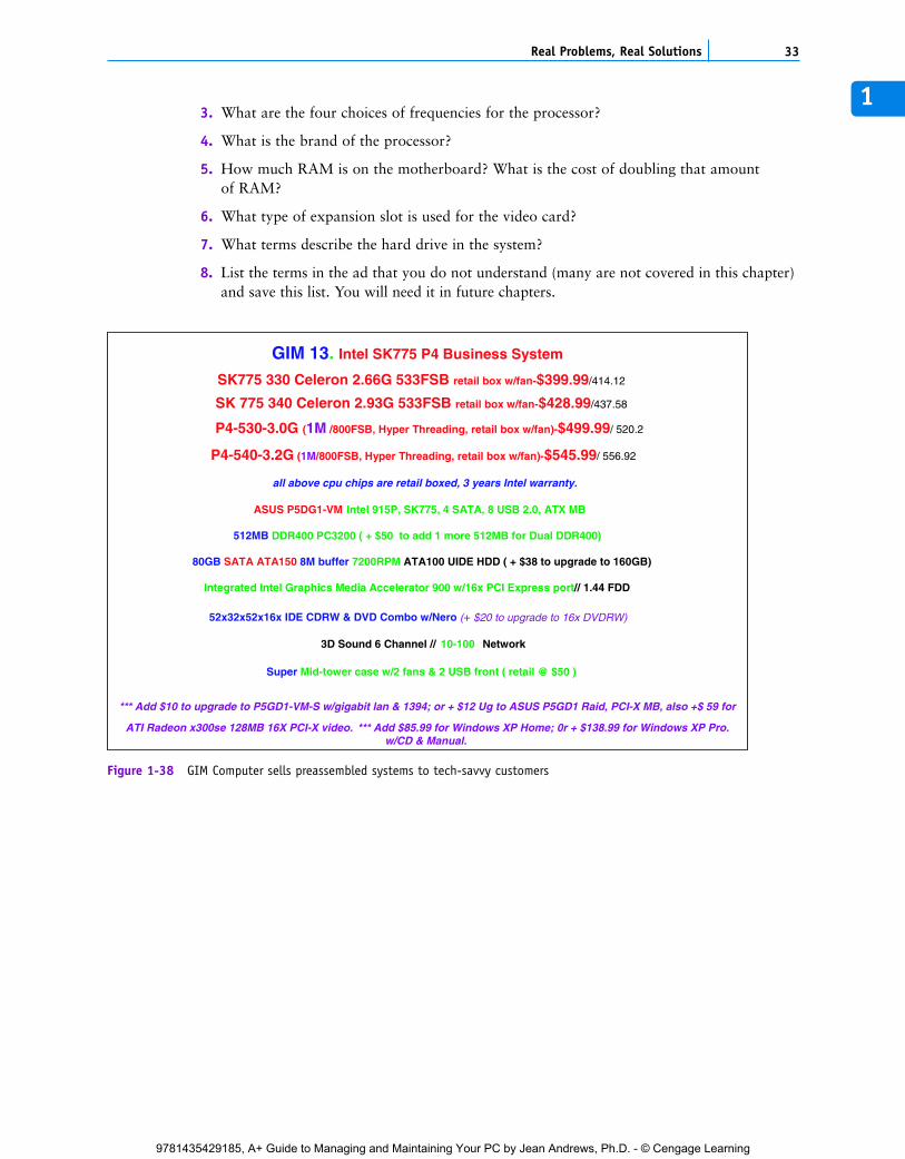
13. What are the four choices of frequencies for the processor?
4. What is the brand of the processor?
5. How much RAM is on the motherboard? What is the cost of doubling that amountof RAM?
6. What type of expansion slot is used for the video card?
7. What terms describe the hard drive in the system?
8. List the terms in the ad that you do not understand (many are not covered in this chapter)and save this list. You will need it in future chapters.
33Real Problems, Real Solutions
GIM 13. Intel SK775 P4 Business System SK775 330 Celeron 2.66G 533FSB retail box w/fan-$399.99/414.12 SK 775 340 Celeron 2.93G 533FSB retail box w/fan-$428.99/437.58
P4-530-3.0G (1M /800FSB, Hyper Threading, retail box w/fan)-$499.99/ 520.2
P4-540-3.2G (1M/800FSB, Hyper Threading, retail box w/fan)-$545.99/ 556.92
all above cpu chips are retail boxed, 3 years Intel warranty. ASUS P5DG1-VM Intel 915P, SK775, 4 SATA, 8 USB 2.0, ATX MB
512MB DDR400 PC3200 ( + $50 to add 1 more 512MB for Dual DDR400) 80GB SATA ATA150 8M buffer 7200RPM ATA100 UIDE HDD ( + $38 to upgrade to 160GB)
Integrated Intel Graphics Media Accelerator 900 w/16x PCI Express port// 1.44 FDD
52x32x52x16x IDE CDRW & DVD Combo w/Nero (+ $20 to upgrade to 16x DVDRW) 3D Sound 6 Channel // 10-100 Network
Super Mid-tower case w/2 fans & 2 USB front ( retail @ $50 )
*** Add $10 to upgrade to P5GD1-VM-S w/gigabit lan & 1394; or + $12 Ug to ASUS P5GD1 Raid, PCI-X MB, also +$ 59 for
ATI Radeon x300se 128MB 16X PCI-X video. *** Add $85.99 for Windows XP Home; 0r + $138.99 for Windows XP Pro.w/CD & Manual.
Figure 1-38 GIM Computer sells preassembled systems to tech-savvy customers
C5865_01_CTP.qxd 9/22/06 5:18 PM Page 33
9781435429185, A+ Guide to Managing and Maintaining Your PC by Jean Andrews, Ph.D. - © Cengage Learning
Related Documents