CHAPTER III MATERIALS AND METHODS 3.1 General This chapter deals with the materials used and methods adopted to conduct study on the characteristics of pervious concrete. 3.2 Material used 3.2.1 Cement Cement is a fine, soft, powdery-type substance made from a mixture of elements that are found in natural materials such as limestone, clay, sand or shale . Cement is usually of grey colour. White cement can also be found but it is usually more expensive than gray cement. Cement is a binding substance with adhesive and cohesive properties which sets and hardens independently and binds other materials into a compact-solid . When cement is mixed with water, it can bind sand and gravel into a hard solid mass called concrete. When cement is mixed with water, lime and sand it forms mortar. The cement contains two basic ingredients namely argillaceous and calcareous. Ordinary Portland Cement ( OPC) is the most important type of cement. OPC is classified into three grades, namely 33 grade, 43 grade and 53 grade depending upon the compressive strength of cement at 28 days. . Portland cement concrete is foremost used among the construction materials around the world because it is very versatile, economical and widespread availability of its constituents . Shree Ultra 43 grade OPC was used in this study. It was fresh and free from any lumps. The properties of cement were determined and are given in chapter IV.

Welcome message from author
This document is posted to help you gain knowledge. Please leave a comment to let me know what you think about it! Share it to your friends and learn new things together.
Transcript
CHAPTER III
MATERIALS AND METHODS
3.1 General
This chapter deals with the materials used and methods adopted to conduct study on the
characteristics of pervious concrete.
3.2 Material used
3.2.1 Cement
Cement is a fine, soft, powdery-type substance made from a mixture of elements that are found in
natural materials such as limestone, clay, sand or shale. Cement is usually of grey colour. White cement
can also be found but it is usually more expensive than gray cement. Cement is a binding substance with
adhesive and cohesive properties which sets and hardens independently and binds other materials into a
compact-solid. When cement is mixed with water, it can bind sand and gravel into a hard solid mass
called concrete. When cement is mixed with water, lime and sand it forms mortar. The cement contains
two basic ingredients namely argillaceous and calcareous. Ordinary Portland Cement (OPC) is the most
important type of cement. OPC is classified into three grades, namely 33 grade, 43 grade and 53 grade
depending upon the compressive strength of cement at 28 days. . Portland cement concrete is foremost
used among the construction materials around the world because it is very versatile, economical and
widespread availability of its constituents.
Shree Ultra 43 grade OPC was used in this study. It was fresh and free from any lumps. The
properties of cement were determined and are given in chapter IV.
Shree Ultra OPC

3.2.2 Aggregate
Aggregates are the most mined materials in the world. They are a component of composite
materials such as concrete and asphalt concrete. Generally, aggregates occupy 70% to 80% of the volume
of concrete and have an important influence on its properties. The aggregate serves as dimensional
stability and reinforcement to add strength to the overall composite material. They are granular materials,
derived from natural rock (crushed stone, or natural gravels). Due to the relatively high hydraulic
conductivity value as compared to most soils, aggregates are widely used in drainage applications . For a
good concrete mix, aggregates need to be clean, hard, strong particles free of absorbed chemicals or
coatings of clay and other fine materials that could cause the deterioration of concrete. Soft and porous
rock can limit strength and wear resistance and sometimes it may also break down during mixing and
adversely affect workability by increasing the amount of fines. Using washed aggregates normally gives a
more consistent product. The shape and particle size distribution of the aggregate is very important and
affects the packing and voids content. Single size aggregates and/or a gap in the grading between coarse
and fine aggregates are used in some mix designs.
3.2.2.1 Coarse aggregate
Coarse aggregates are particles greater than 4.75mm, but generally range between 9.5mm to
40mm in diameter and contain only that much of fine material as is permitted by the specifications. The
graded coarse aggregate is described by its nominal size i.e. 40 mm, 20 mm, 16 mm, 12.5mm and 10 mm.
They can either be from primary source (rock or gravel), secondary source (by-products of extractive
operations) or recycled sources (used concrete). The aggregates derive many of their properties such as
chemical and mineral composition, specific gravity, hardness, strength, pore structure and colour from the
parent rocks. All these properties may have considerable effect on the quality of concrete. The particle
size distribution and the shape of coarse aggregate directly influence the flow and passing ability of
pervious concrete and its paste demand. More the spherical shape aggregates in mix, less they are likely
to cause blocking and greater the flow because of reduced internal friction. Crushed stone aggregate
(locally available) of nominal size 40mm, 20 mm and 10 mm were used in the various proportion
throughout the experimental study. The aggregates were washed to remove dust and dirt and were dried to
surface dry condition. The properties of coarse aggregates such as specific gravity, bulk density and water
abroption were determined and are given in chapter IV.
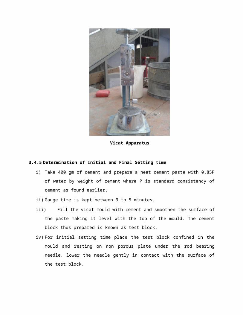
10mm 20mm 40mm
3.2.2.2 Fine aggregate
No fine aggregates have been used.
3.2.3 Water
Fresh and clean tap water was used for casting the specimens in the present study. The water was
relatively free from organic matter, silt, oil, sugar, chloride and acidic material as per Indian standard.
3.3 Mix Proportion and Mix design method
For mix proportion selection three trial mixes with different cement - aggregates ratio (i.e. 1:4,
1:6, 1:8) were selected keeping w/c ratio constant. All three trials were performed on the same aggregates
proportion of 10mm, 20mm and 40mm (i.e. 1:1:2) respectively. After 28 days compressive strength and
porosity of mixes were calculated and from the observed data, 1:8 gives best results and prove to be
economical as compared to other two mixes because as 1:4 have more cement slurry which more strength
then other two but reduces the pores and which will affect the permeability and 1:6 gives average result as
compare to 1:8.
The basic steps involved in the concrete mix design can be summarized as follows:
i) Based on the literature the mean target strength is estimated
ii) The water cement ratio is selected for the mean target strength and checked for the requirements
of durability.
iii) The water content for the required workability is determined.
iv) The cement content to be determined from the trial mix ratio and water content obtained in step
(ii) and (iii) respectively and is checked for the water requirements.

v) The relative proportion of coarse aggregates is selected from the characteristic of coarse
aggregate.
vi) The trial mix proportions are determined.
vii) The trial mixes are tested for verifying the compressive strength and suitable adjustments are
made to arrive at the final mix composition.
3.4 METHODS
The procedure of methods used for testing cement, coarse aggregates, and concrete are given
below:
3.4.1 Specific gravity
The specific gravity is a dimensionless unit defined as the ratio of the density (mass of a unit
volume) of a substance to the density (mass of the same unit volume) of a reference substance. The
reference substance is water for liquids or air for gases. The specific gravity of the solid is the ratio of its
weight in air to the difference between its weight in air and its weight immersed in water.
3.4.2 Bulk Density
Unit weight (bulk density) is the weight of unit volume of aggregates, usually stated in Kg per
litre. It was calculated to know the estimating quantities of material when batching is done on a
volumetric basis. Bulk density of aggregates is the ratio of weight of loose aggregates and the volume of
container.
Loose Bulk density=(wt .of container+loose aggregates )−(wt of empty container )
volume of container
3.4.3 Fineness of cement
i) Weigh accurately 100gm of cement in rice plate.
ii) Place it on standard IS 90 micron sieve breaking down any air-set lumps in the cement sample
with fingers.
iii) Continuously sieve the sample by holding the sieve in both the hands. Sieve with a gentle wrist
motion for period of 15 minutes.
iv) Weigh the residue after 15 minutes of sieving.
v) Repeat the procedure for two more such samples.
Fineness of cement = (weight of residue / weight of sample) X 100 = ........%

Fineness of Cement
3.4.4 Standard consistency of cement
The standard consistency of a cement paste is defined as that consistency which will permit a
vicat plunger having 10 mm diameter and 50 mm length to penetrate to a depth of 33-35 mm from the top
of the mould.
i) Weigh approximately 400 gm of cement and mix it with a weighed quantity of water. The time
of gauging should be between 3 to 5 minutes.
ii) Fill the vicat mould with paste and level it with a trowel.
iii) Lower the plunger gently till it touches the cement surface.
iv) Release the plunger allowing it to sink into the paste.
v) Note the reading on the gauge.
vi) Repeat the above procedure taking fresh samples of cement and different quantities of water
until the reading on the gauge is 5 mm to 7 mm.

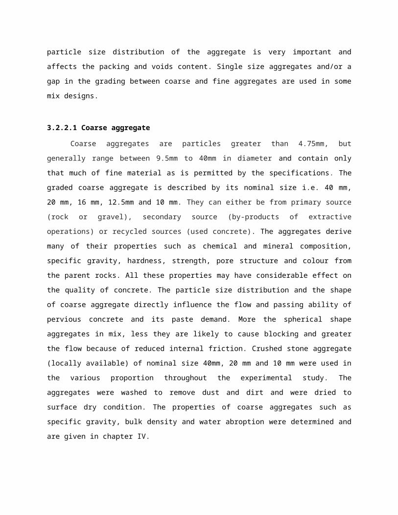
Vicat Apparatus
3.4.5 Determination of Initial and Final Setting time
i) Take 400 gm of cement and prepare a neat cement paste with 0.85P of water by weight of
cement where P is standard consistency of cement as found earlier.
ii) Gauge time is kept between 3 to 5 minutes.
iii) Fill the vicat mould with cement and smoothen the surface of the paste making it level with the
top of the mould. The cement block thus prepared is known as test block.
iv) For initial setting time place the test block confined in the mould and resting on non porous plate
under the rod bearing needle, lower the needle gently in contact with the surface of the test
block.
v) In the beginning the needle completely pierces the test block. Repeat this procedure until the
needle fails to pierce the block for about 5 mm measured from the bottom of the mould.
vi) The period elapsing between the time when water is added to the time at which the needle fails
to pierce the test block by about 5 mm is the initial setting time.
vii) For determining the final setting time, replace the needle of vicat apparatus by the needle with an
annular attachment.

viii) The cement is considered finally set when upon applying the final setting needle gently to the
surface of the block, the needle makes an impression thereon, while the attachment fails to do so.
The period elapsing between the time when water is added to the cement and the time at which
the needle makes an impression on the surface of the test block while the attachment fails to do
so shall be the final setting time.
3.4.6 Determination of compressive strength of cement
Compressive strength of cement is determined from cubes of 70.6 mm X 70.6 mm X 70.6 mm in
size, made of cement mortar with one part of cement and three parts of standard sand.
The quantity of materials for each cube taken as follows:-
Cement : 200 gm
Standard sand : 600 gm
Water = (P/4+3.0) percent weight of cement and sand
Where P is the percentage of water required to produce a paste of standard consistency determined as
described in IS: 4031 (part 4) -1988.
Procedure:
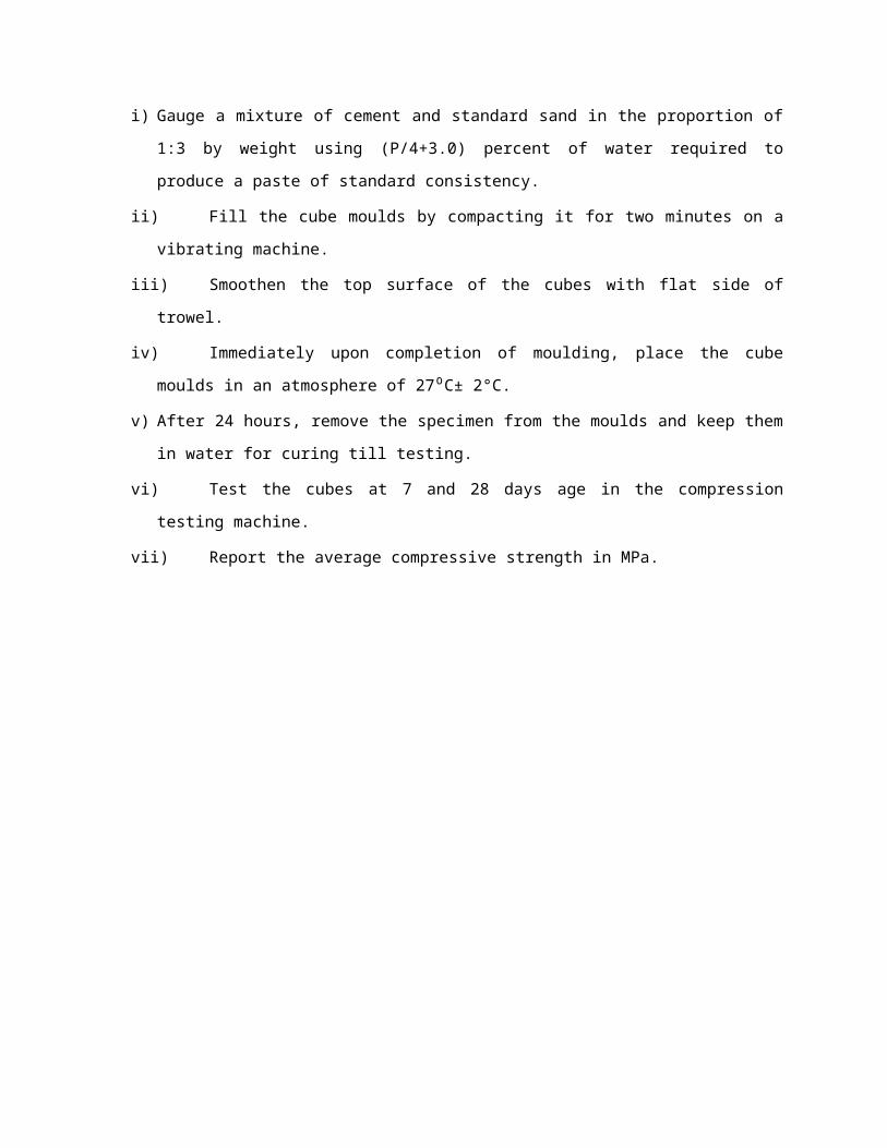
i) Gauge a mixture of cement and standard sand in the proportion of 1:3 by weight using (P/4+3.0)
percent of water required to produce a paste of standard consistency.
ii) Fill the cube moulds by compacting it for two minutes on a vibrating machine.
iii) Smoothen the top surface of the cubes with flat side of trowel.
iv) Immediately upon completion of moulding, place the cube moulds in an atmosphere of 27 C±⁰
2°C.
v) After 24 hours, remove the specimen from the moulds and keep them in water for curing till
testing.
vi) Test the cubes at 7 and 28 days age in the compression testing machine.
vii) Report the average compressive strength in MPa.
Tester Cubes Compression testing machine
3.4.7 Workability of Pervious Concrete
Workability is that property of freshly mixed concrete or mortar which determines the ease and
homogeneity with which it can be mixed, placed, consolidated, and finished. Workability is not just based
on the properties of the concrete, but also on the nature of the application. The strength and durability of
hardened concrete, in addition to labour costs, depend on concrete having appropriate workability.
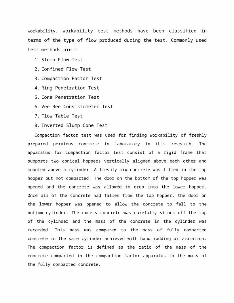
Workability test methods have been classified in terms of the type of flow produced during the
test. Commonly used test methods are:-
1. Slump Flow Test
2. Confined Flow Test
3. Compaction Factor Test
4. Ring Penetration Test
5. Cone Penetration Test
6. Vee Bee Consistometer Test
7. Flow Table Test
8. Inverted Slump Cone Test
Compaction factor test was used for finding workability of freshly prepared pervious concrete in
laboratory in this research. The apparatus for compaction factor test consist of a rigid frame that supports

two conical hoppers vertically aligned above each other and mounted above a cylinder. A freshly mix
concrete was filled in the top hopper but not compacted. The door on the bottom of the top hopper was
opened and the concrete was allowed to drop into the lower hopper. Once all of the concrete had fallen
from the top hopper, the door on the lower hopper was opened to allow the concrete to fall to the bottom
cylinder. The excess concrete was carefully struck off the top of the cylinder and the mass of the concrete
in the cylinder was recorded. This mass was compared to the mass of fully compacted concrete in the
same cylinder achieved with hand rodding or vibration. The compaction factor is defined as the ratio of
the mass of the concrete compacted in the compaction factor apparatus to the mass of the fully compacted
concrete.
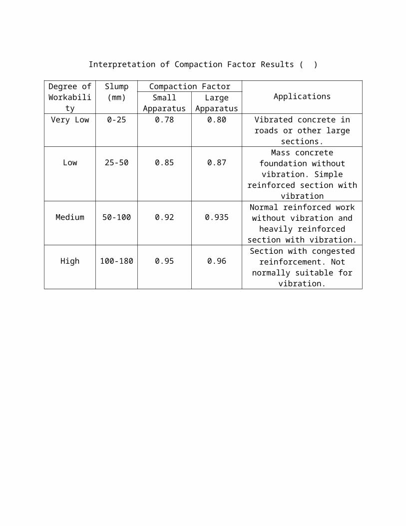
Interpretation of Compaction Factor Results ( )
Degree of Workability
Slump(mm)
Compaction FactorApplicationsSmall
ApparatusLarge
ApparatusVery Low 0-25 0.78 0.80 Vibrated concrete in roads or other
large sections.
Low 25-50 0.85 0.87Mass concrete foundation without
vibration. Simple reinforced section with vibration
Medium 50-100 0.92 0.935Normal reinforced work without vibration and heavily reinforced
section with vibration.
High 100-180 0.95 0.96Section with congested
reinforcement. Not normally suitable for vibration.

3.4.8 Compressive strength of Pervious Concrete
The quantities of cement, coarse aggregates (40mm, 20 mm and 10 mm) and water for each batch
were weighed separately. All three sizes of aggregates were placed in the mixer and mixed for 2 minutes.
The cement was mixed dry with the aggregates in mixer. Water was added to the mix and then mixed
thoroughly for 3 to 4 minutes in mixer.
Cube moulds were cleaned and oil was applied on its inner surface. The mould was filled 1/ 3
with the concrete and manual compaction was done with 25 strokes of tamping rod. Again the process
was repeated 2 more times for completely filling the mould. The surface of the concrete was finished
level with the top of the mould using trowel. The finished specimens were left to harden in air for 24
hours. The specimens were removed from the moulds after 24 hours of casting and were placed in the
water tank, filled with potable water in the laboratory.
Specimens were taken out from the curing tank at the ages of 7, 14 and 28 days. Surface water
was wiped off and specimens were immediately tested on removal from the curing tank. The load was
applied gradually without shock till the failure of the specimen occur and thus the compressive strength of
concrete cubes was found.
3.4.9 Void ratio of Pervious Concrete
Void ratio (e) of any concrete specimen is defined as the ratio of volume of voids (Vv) to the
volume of solids (Vs). Void Ratio (e) is also related to porosity (n). Strength of the concrete specimen can
be judged from its void ratio. As higher the void ratio lower will be the strength and vice versa. Void ratio
(e) is found by simple experiment performed in a laboratory by submerging the 28 days cured cube in the
bucket filled with water. A hole was made in the bucket to maintain the constant level of water. The cube
was submerged in the bucket and the water level in the bucket will rise. The cube was allowed to sit
saturate. When air bubbles disappear, the hole in the bucket as opened and water was allowed to escape
from the bucket and collected in jars. The volume of displaced water was measured accurately measuring
jar. This volume of water is equal to the volume of solids (Vs). Volume of solid (Vs) was subtracted from
the total volume of cube (V) (150mm X 150mm X150mm) to find the volume of voids (Vv) in the cube
specimen. Void ratio (e) was derived from the formula:-
Void Ratio , e= Volumeof voidsVolumeof solids
=VvVs
=V−VsVs
Porosity , n=Volume of voidsTotalVolume
=VvV
=V−VsV
The relationship between void ratio (e) and porosity (n) ids expressed as:-
n= e1+e
3.4.10 Permeability of Pervious ConcretePermeability of concrete generally refers to the rate at which water or other aggressive
substance (sulphates, chlorides ions, etc.) can penetrate concrete. It plays an important role in the
long-term durability of concrete. Lower the permeability higher the durability of concrete. But in
pervious concrete the permeability should be high for allowing infiltration and percolation of storm
water to underlying soil, reducing runoff volume, peak flow, pollutant loads and facilitating
groundwater recharge. Permeability of concrete primarily depends upon its porosity. There are different
methods for finding the permeability of concrete and they are:-
1. Constant Head Method
The basic concept of Constant Head Method is to make water flow through concrete
under constant pressure and measure the flow rate under Steady – State flow condition. The
specimens were placed in the test cells and the annular space was filled with some sealing
compound so that the flow occurred only in one direction i.e. from top to bottom.
Measurements were taken at the bottom surface after achieving the Steady-State flow
condition. Darcy’s law has been used to determine the co-efficient of permeability. The
equation used is
K s=QLAH
Where, Ks – Coefficient of saturated permeability (m/s)
Q – Volume of flow rate (m3/s)
A – Cross-sectional area (m2)
L – Specimen thickness in the direction of flow (m)
H – Head of water causing flow (m)
2. Falling Head Method
The falling head permeability test involves flow of water through a sample connected to a
standpipe which provides the water head and also allows measuring the volume of water passing through
the sample. Before starting the flow measurements, the sample is saturated and the standpipes are filled
with water to a given level. The test then starts by allowing water to flow through the sample until the
water in the standpipe reaches a given lower limit. The time required for the water in the standpipe to
drop from the upper to the lower level is recorded. Often, the standpipe is refilled and the test is repeated
for couple of times. The recorded time should be the same for each test within an allowable variation of
about 10% (Head 1982) otherwise the test is failed. On the basis of the test results, the permeability of the
sample can be determined by Darcy’s law. The general expression for ‘k’ is
K s= aLA(t 1−t 0)
logeh0
h1
Where, Ks – Coefficient of saturated permeability (m/s)
A – Cross section area of sample (m2)
L – Height of the sample column (m)
a – Cross section area of the standpipe (m2)
(t1 – t0) – Recorded time for water column to flow through the sample (sec)
h0 – Upper water level in the standpipe measured using the same water head reference
h1 – Lower water level in the standpipe measured using the same water head
reference
Out of these two constant head method was adopted for the research. Apparatus was prepared
from the local market. Research experiments were performed at tubwell because high flow rate of water is
required to perform the experiment. After creating a constant head, the outlet water is collected in bucket
3 times for each specimen and time of flow was recorded with the help of stop watch.

Constant Head Apparatus
Related Documents