CHAPTER II SINUSOIDAL STEADY STATE ANALYSIS “Alternating Current Circuits (A.C.)” 1

Welcome message from author
This document is posted to help you gain knowledge. Please leave a comment to let me know what you think about it! Share it to your friends and learn new things together.
Transcript

CHAPTER II
SINUSOIDAL STEADY STATE ANALYSIS
“Alternating Current Circuits (A.C.)”
1
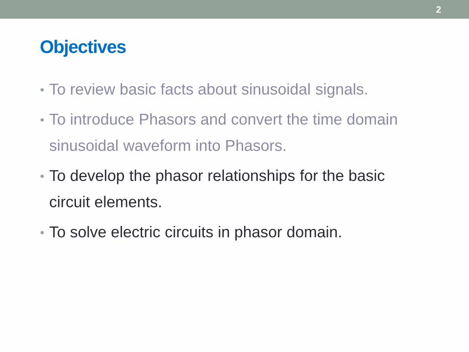
Objectives
• To review basic facts about sinusoidal signals.
• To introduce Phasors and convert the time domain
sinusoidal waveform into Phasors.
• To develop the phasor relationships for the basic
circuit elements.
• To solve electric circuits in phasor domain.
2
Sinusoids
3
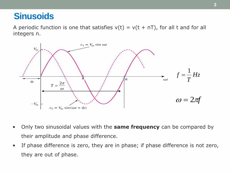
A periodic function is one that satisfies v(t) = v(t + nT), for all t and for all integers n.
2T
HzT
f1
f 2
• Only two sinusoidal values with the same frequency can be compared by
their amplitude and phase difference.
• If phase difference is zero, they are in phase; if phase difference is not zero,
they are out of phase.
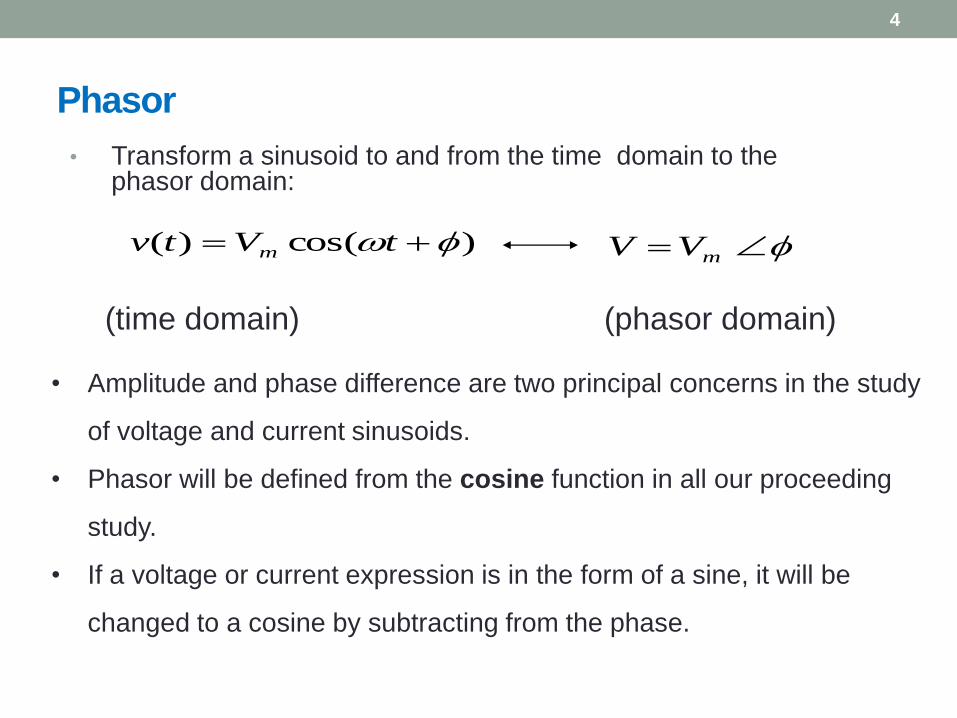
Phasor
• Transform a sinusoid to and from the time domain to the phasor domain:
(time domain) (phasor domain)
4
)cos()( tVtv m mVV
• Amplitude and phase difference are two principal concerns in the study
of voltage and current sinusoids.
• Phasor will be defined from the cosine function in all our proceeding
study.
• If a voltage or current expression is in the form of a sine, it will be
changed to a cosine by subtracting from the phase.

Phasor
The differences between v(t) and V:
• v(t) is instantaneous or time-domain representation
V is the frequency or phasor-domain representation.
• v(t) is time dependent, V is not.
• v(t) is always real with no complex term, V is generally
complex.
Note: Phasor analysis applies only when frequency is
constant; when it is applied to two or more sinusoid
signals only if they have the same frequency.
5

Sinusoid-Phasor Transformation
6

The Phasor
• A phasor is a complex number that
represents the amplitude and phase
of a sinusoid.
• It can be represented in one of the
following three forms:
7
rz
jrez
)sin(cos jrjyxz a. Rectangular
b. Polar
c. Exponential22 yxr
x
y1tanwhere
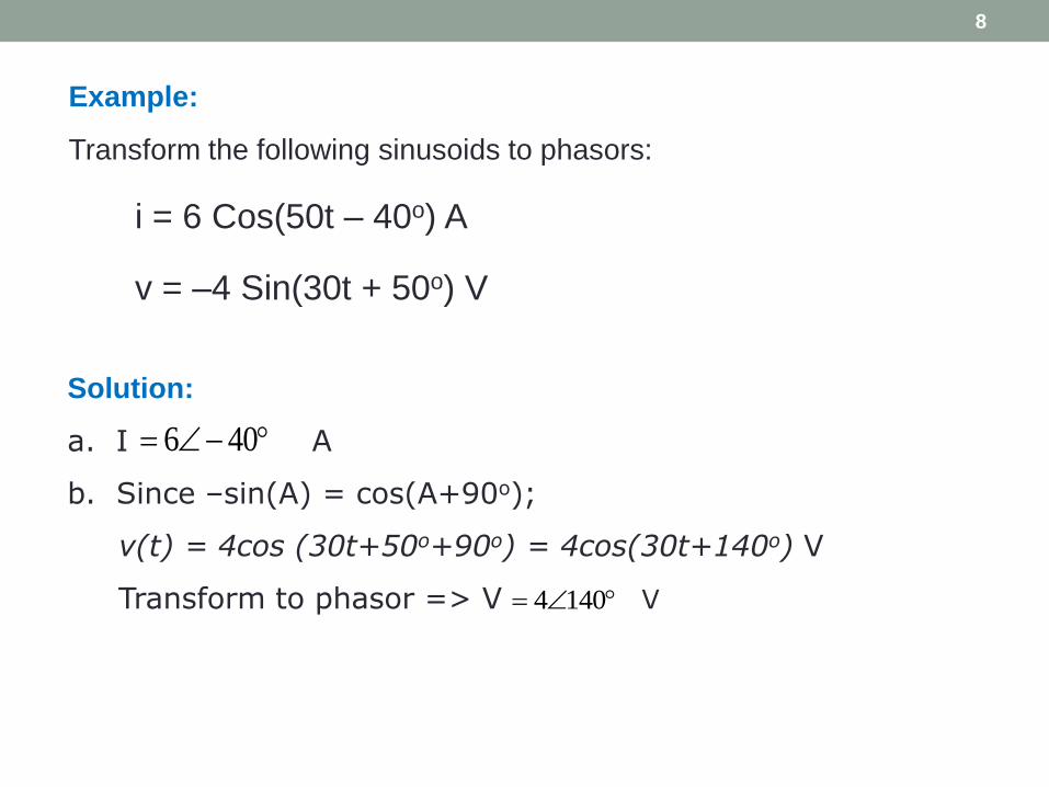
Example:
Transform the following sinusoids to phasors:
i = 6 Cos(50t – 40o) A
v = –4 Sin(30t + 50o) V
8
Solution:
a. I A
b. Since –sin(A) = cos(A+90o);
v(t) = 4cos (30t+50o+90o) = 4cos(30t+140o) V
Transform to phasor => V V
406
1404
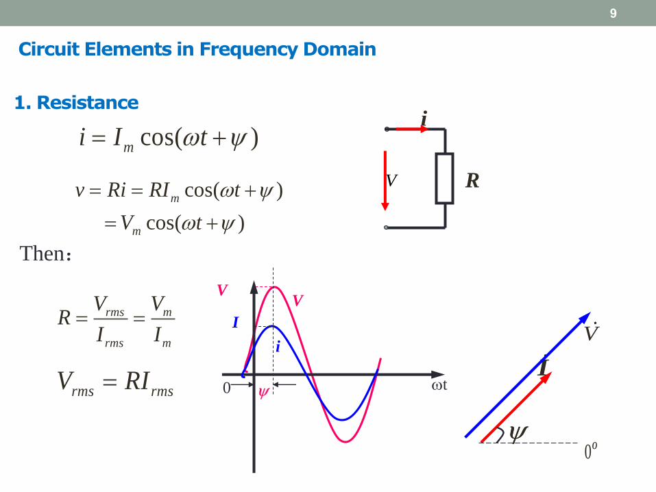
Circuit Elements in Frequency Domain
9
VV
i
I
0 t
RV
icos( )mi I t
cos( )
cos( )
m
m
v Ri RI t
V t
rms rmsV RI
rms m
rms m
V VR
I I
Then:
1. Resistance
IV
O0

10

V, i have the same
frequency,V leads i
by 90o
i
Vπ 2π
0 ωt
2. Inductance
11
Relationship between voltage and current
sinmi I t
0cos sin( 90 )m m
div L LI t V t
dt

rms rmsV LI m mV LI
Reactance XL
sinmi I t 0sin( 90 )mv V t
Sinusoidal response of Inductance
12
Effective Value

13

i
v C
sinmv V t
0
0
sin( 90 )
sin( 90 )
m
m
dvi C C U t
dt
I t
Current leads voltage by 90°
2m m mI CV fCV Vi
20
3. Capacitors
14
Relationship between voltage and current

15

Summary of voltage-current relationship
Element Time domain Frequency
domain
R
L
C
Riv RIV
dt
diLv LIjV
dt
dvCi
Cj
IV

Example

18
Answer: i(t) = 30 cos(100t + 60o) mA
19
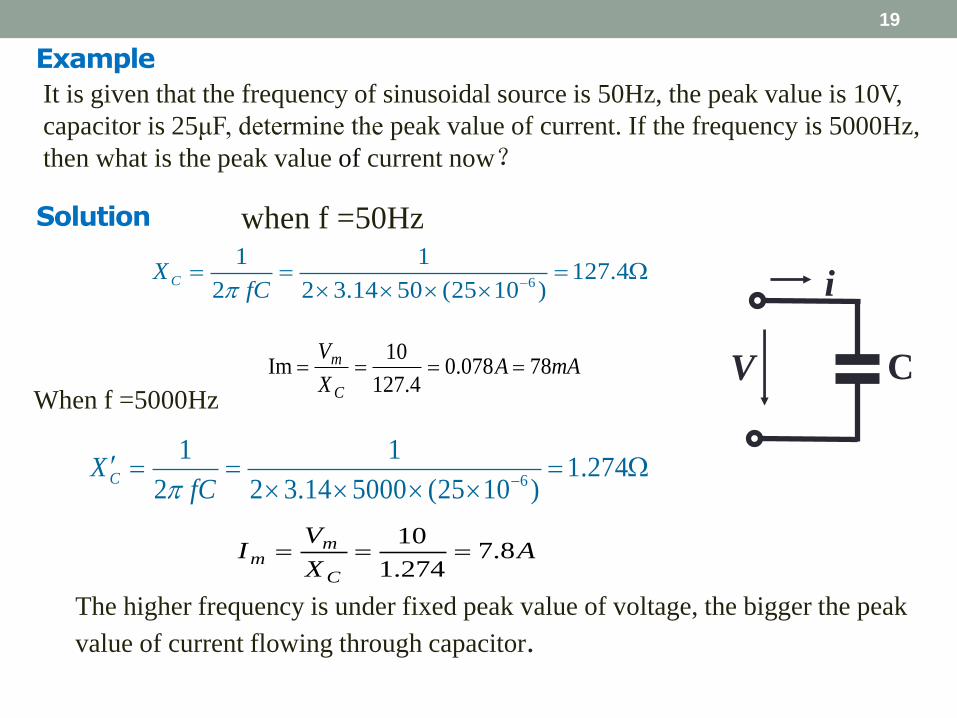
It is given that the frequency of sinusoidal source is 50Hz, the peak value is 10V,
capacitor is 25μF, determine the peak value of current. If the frequency is 5000Hz,
then what is the peak value of current now?
i
V C
when f =50Hz
6
1 1127.4
2 2 3.14 50 (25 10 )CX
fC
mAAX
V
C
m 78078.04.127
10Im
When f =5000Hz
6
1 11.274
2 2 3.14 5000 (25 10 )CX
fC
AX
VI
C
mm 8.7
274.1
10
The higher frequency is under fixed peak value of voltage, the bigger the peak
value of current flowing through capacitor.
Solution
Example

Phasor Domain Sources
20
• Convert time domain elements and sources into phasors
Time Domain Phasor Domain
21
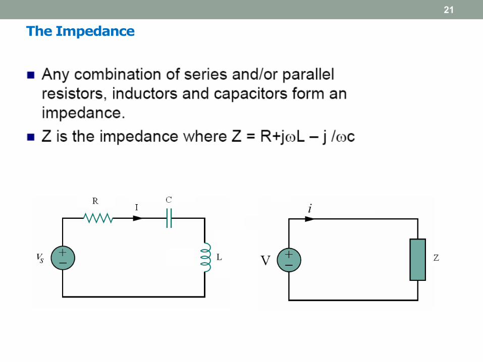
The Impedance
Kirchhoff’s Laws in the Frequency Domain
22
• Both KVL and KCL are hold in the phasor domain or more
commonly called frequency domain.
• Moreover, the variables to be handled are phasors, which
are complex numbers.
• Series and parallel combinations are the same as in D.C.
circuits analysis.
• All the mathematical operations involved are now in
complex domain.

Example
Refer to Figure below, determine v(t) and i(t).
Answers: i(t) = 1.118sin(10t – 26.56o) A; v(t) = 2.236sin(10t + 63.43o) V
23

Impedance Combinations
24
Determine the input impedance of the circuit in figure below
at ω =10 rad/s.
Answer: Zin = 32.38 – j73.76

25

26
Related Documents