Welcome message from author
This document is posted to help you gain knowledge. Please leave a comment to let me know what you think about it! Share it to your friends and learn new things together.
Transcript
� The actual process begins with sampling of the load environment on publish roads.
� The simplified loads can only be applied in the preliminary design stage when the the preliminary design stage when the absence of test or simulation data.
� They should always be qualified and updatedas more information becomes available.

� The significant proving ground events can be divided into two types:
◦ Instantaneous overloads◦ Instantaneous overloads
� (large pot holes, kerb bump, large bump, panic braking, high g cornering, service loads)
◦ Fatigue damage
� (medium size pot holes, Belgium block road, twist course, Cobblestone track, service loads)
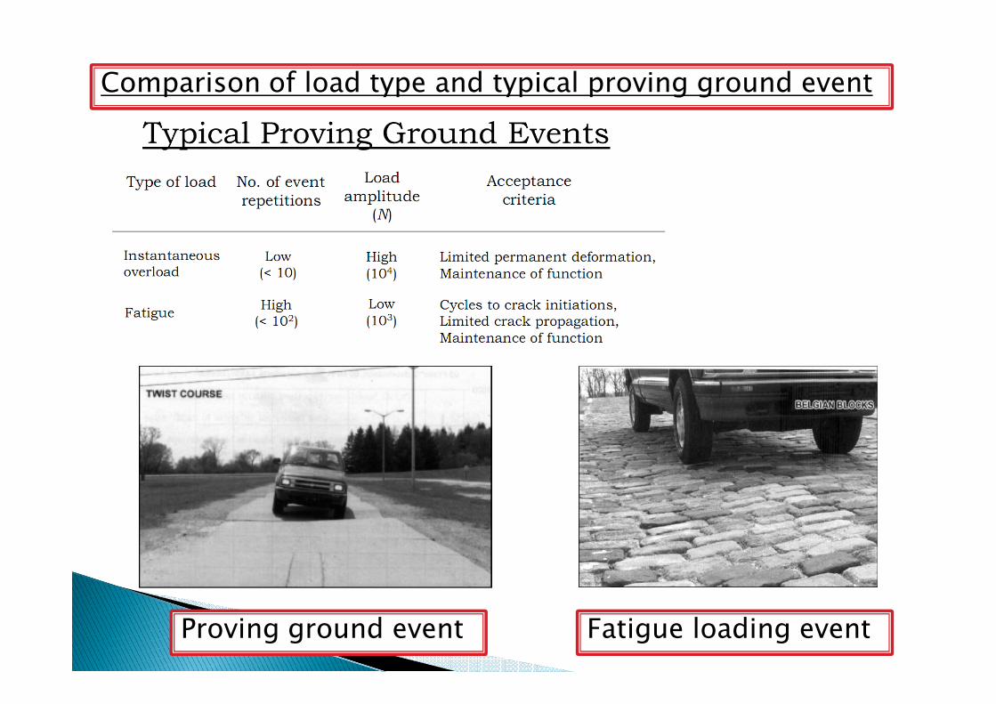
Comparison of load type and typical proving ground event
Fatigue loading eventProving ground event
� The vehicle designer needs to know the worst or most damaging loads in order to:
◦ ensure the structure does not fail in service due to instantaneous overload.instantaneous overload.
◦ ensure a satisfactory fatigue life.
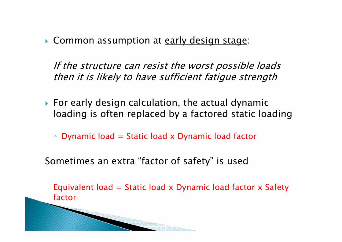
� Common assumption at early design stage:
If the structure can resist the worst possible loads then it is likely to have sufficient fatigue strength
� For early design calculation, the actual dynamic loading is often replaced by a factored static loading
◦ Dynamic load = Static load x Dynamic load factor
Sometimes an extra “factor of safety” is used
Equivalent load = Static load x Dynamic load factor x Safety
factor
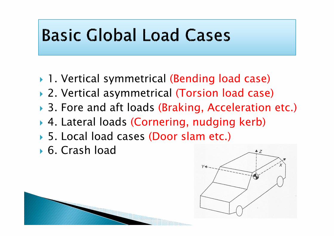
� 1. Vertical symmetrical (Bending load case)
� 2. Vertical asymmetrical (Torsion load case)
� 3. Fore and aft loads (Braking, Acceleration etc.)
4. Lateral loads (Cornering, nudging kerb)� 4. Lateral loads (Cornering, nudging kerb)
� 5. Local load cases (Door slam etc.)
� 6. Crash load
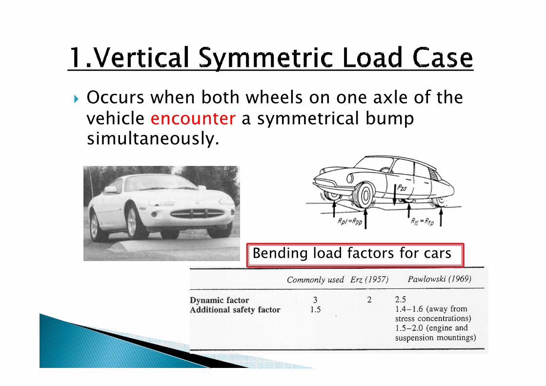
� Occurs when both wheels on one axle of the vehicle encounter a symmetrical bump simultaneously.
Bending load factors for cars
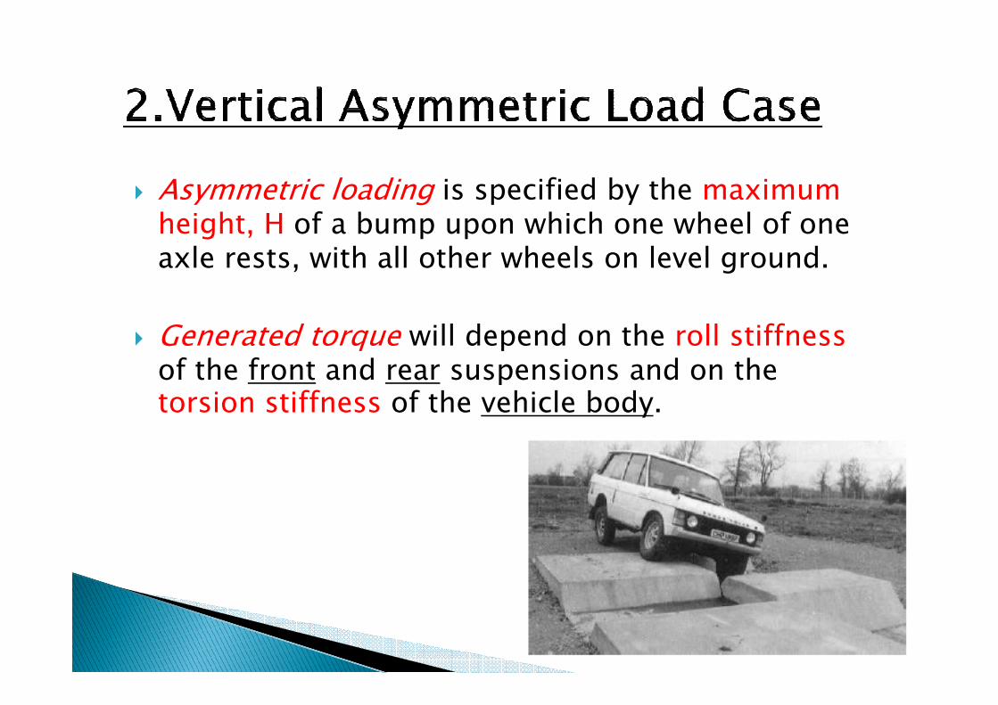
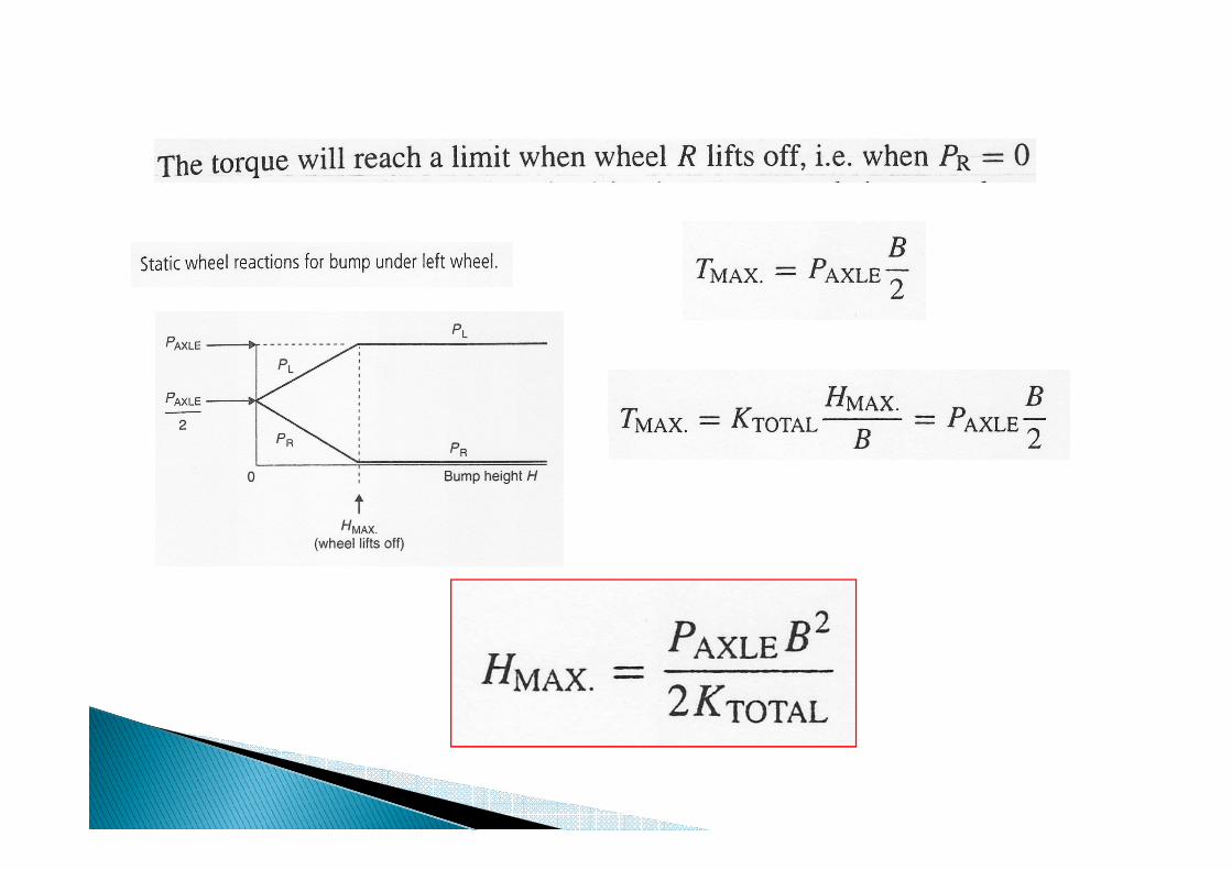
� Asymmetric loading is specified by the maximum height, H of a bump upon which one wheel of one axle rests, with all other wheels on level ground.
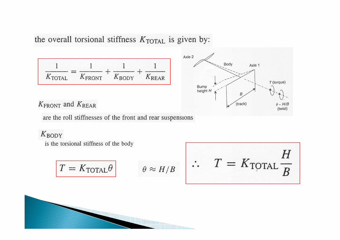
� Generated torque will depend on the roll stiffness of the front and rear suspensions and on the of the front and rear suspensions and on the torsion stiffness of the vehicle body.
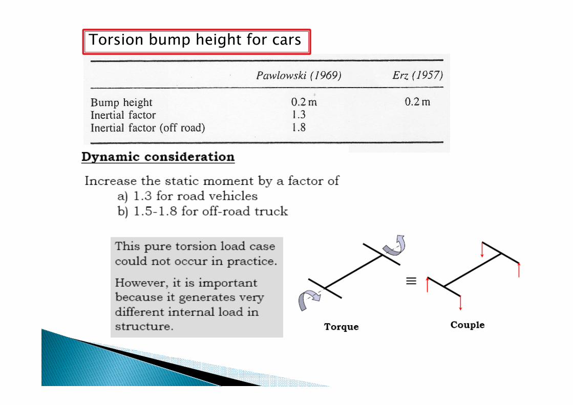
Torsion bump height for cars
� Clutch-drop (or Snap-clutch) loads
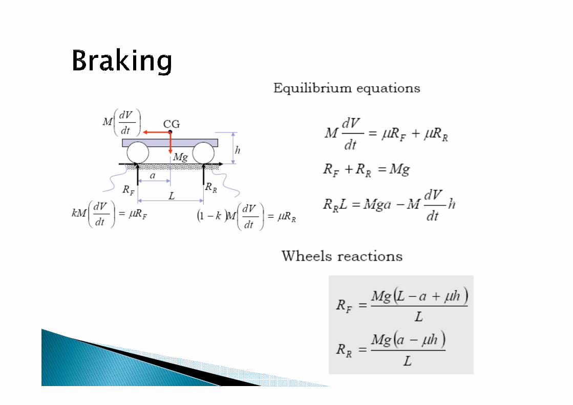
� Accelerating/Braking
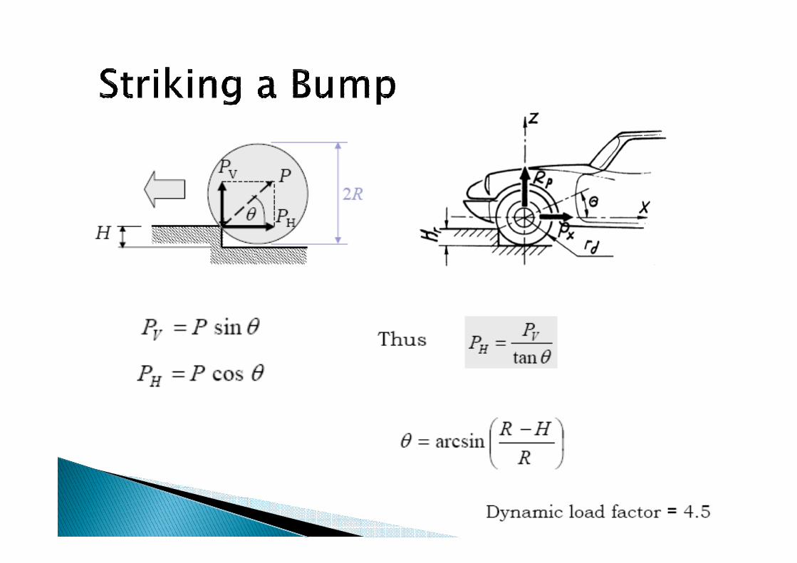
Longitudinal load on striking a bump� Longitudinal load on striking a bump
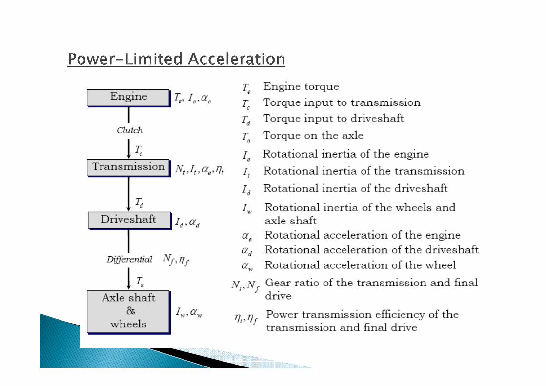
� Maximum performance in longitudinal acceleration of a motor vehicle is determined by one of two limits– engine power or traction limits on the drive wheel
◦ At low speeds tire traction may be the limiting factor.
◦ At high speeds engine power may account for the limits

� 1) Front wheel drive
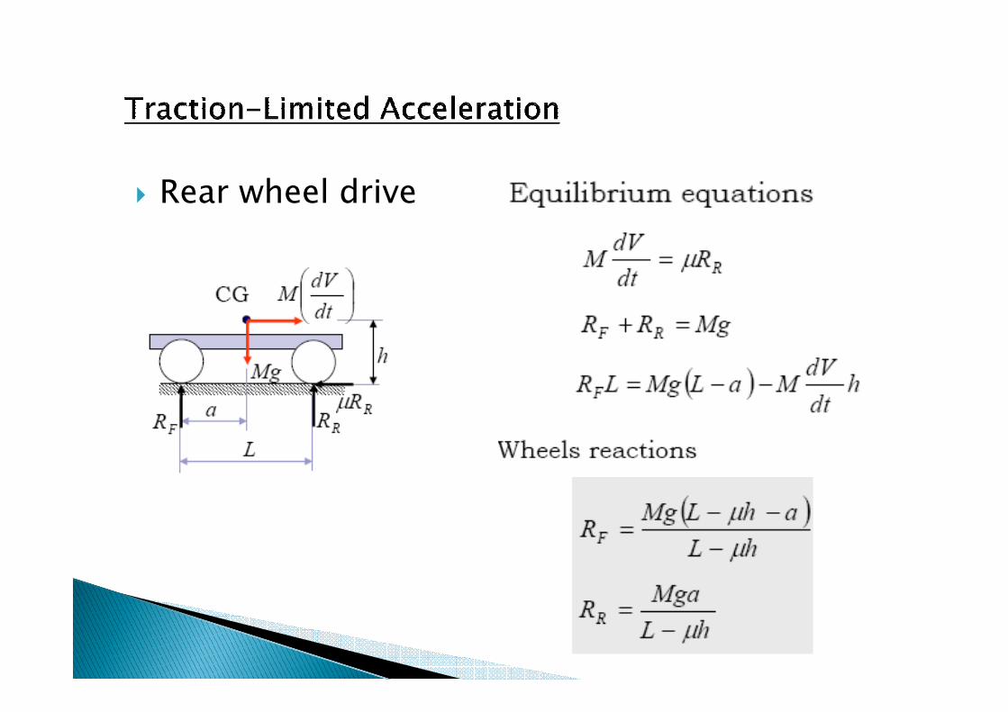
� Rear wheel drive
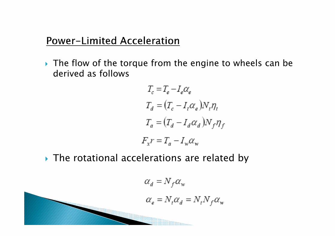
� The flow of the torque from the engine to wheels can be derived as follows
� The rotational accelerations are related by
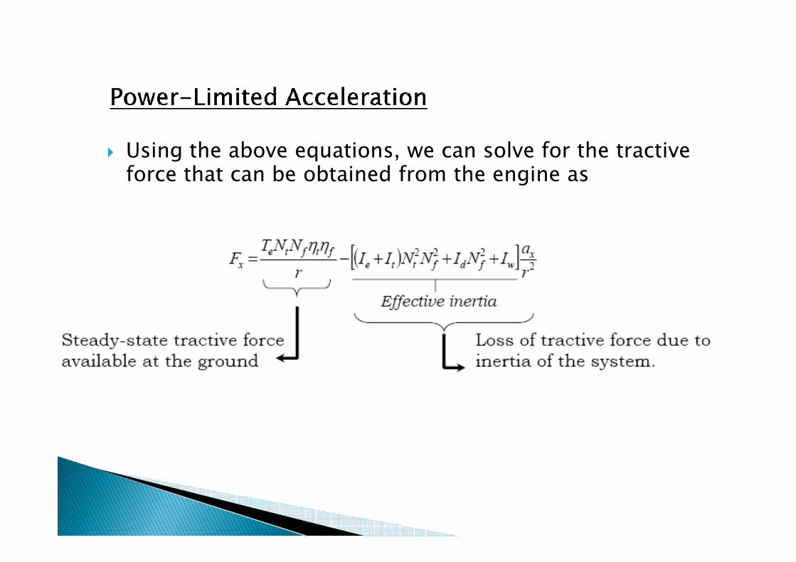
� Using the above equations, we can solve for the tractiveforce that can be obtained from the engine as
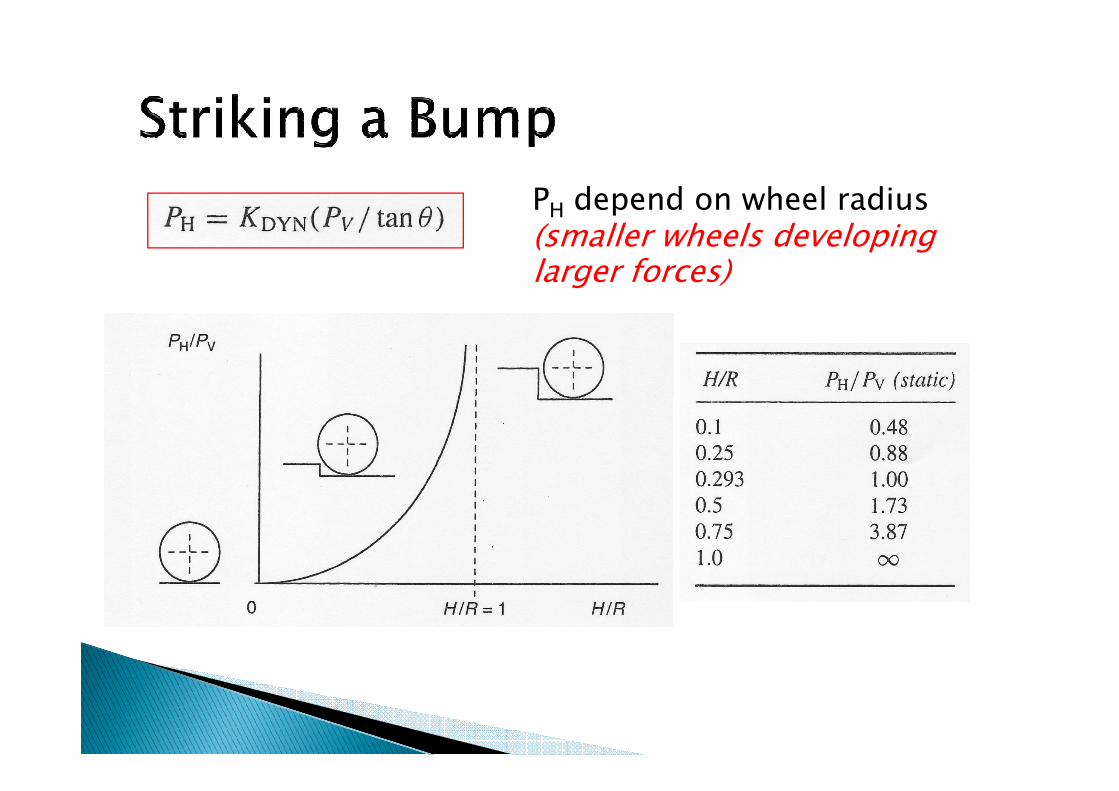
PH depend on wheel radius (smaller wheels developing larger forces)
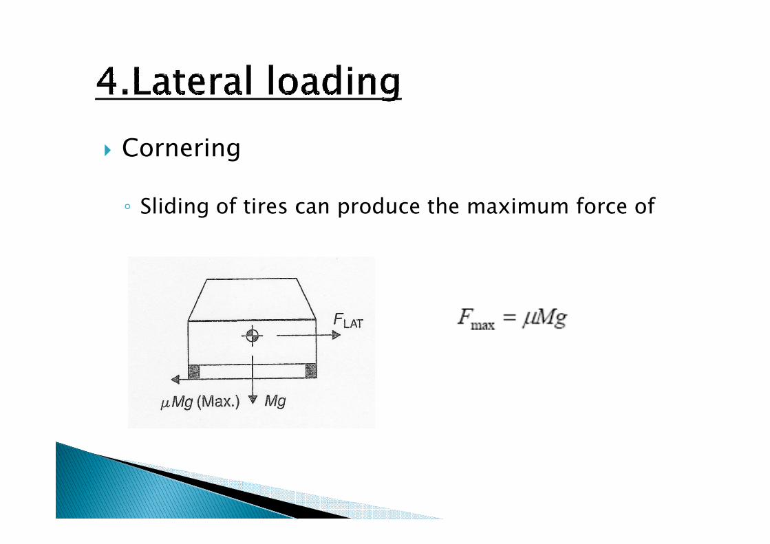
� Cornering
◦ Sliding of tires can produce the maximum force of

� Kerb nudge (Overturning)
◦ The lateral force reaches a maximum when the wheel (A) opposite the kerb just lifts off
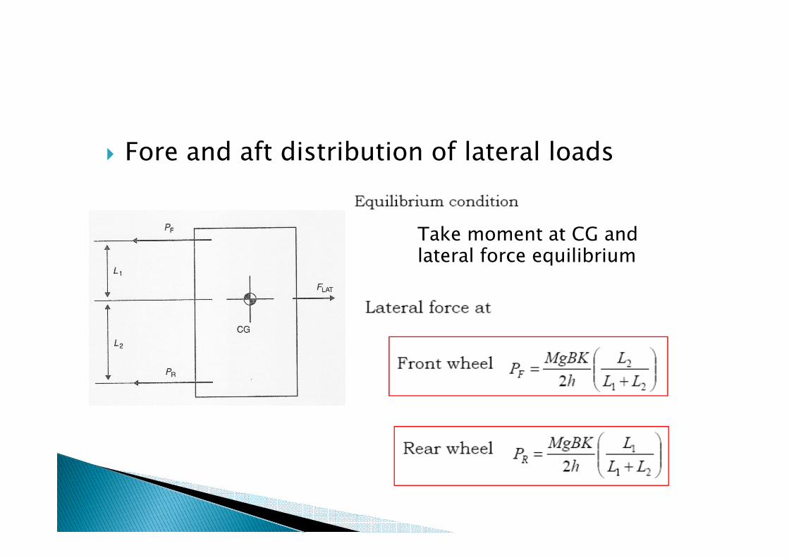
� Fore and aft distribution of lateral loads
Take moment at CG and lateral force equilibrium
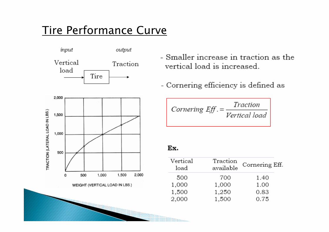
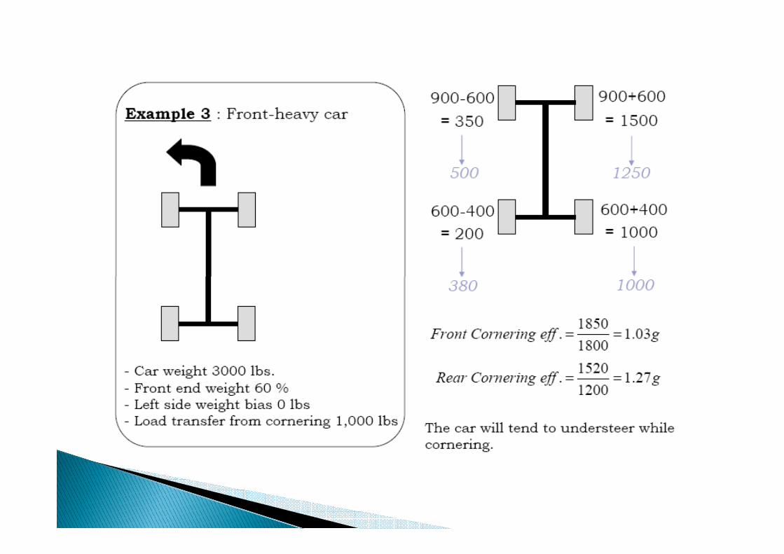
Tire Performance Curve
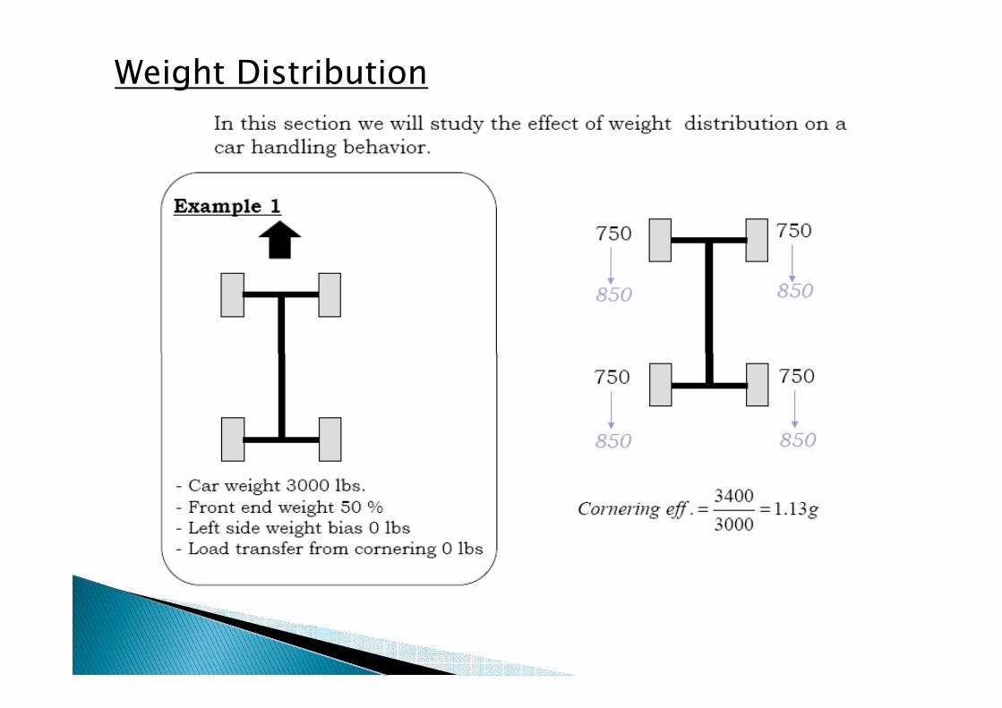
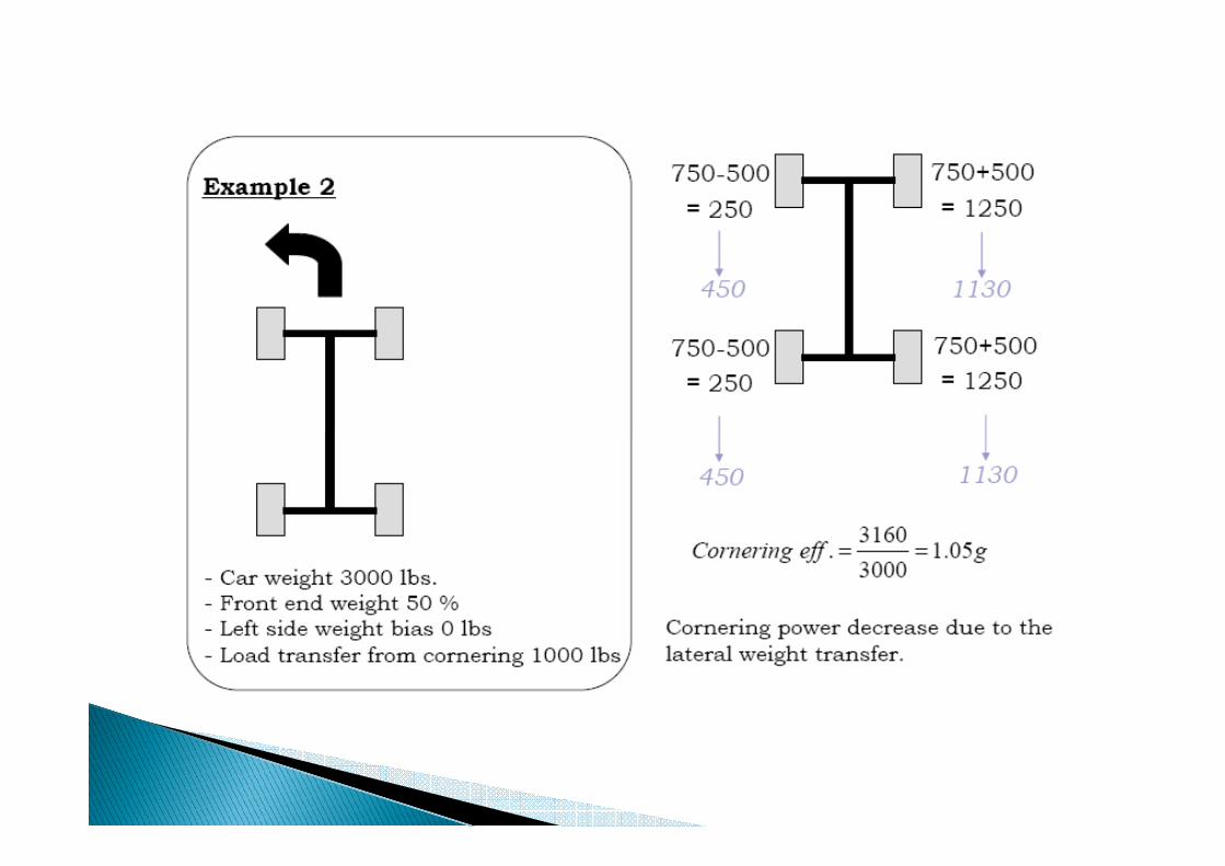
Weight Distribution
� For the aim of calculation◦ All load cases are split into separate idealized cases
◦ The results are then combined (i.e. superposition)
� The main idealized load case are:� The main idealized load case are:◦ Bending
◦ Pure torsion
◦ The lateral cases
◦ The longitudinal
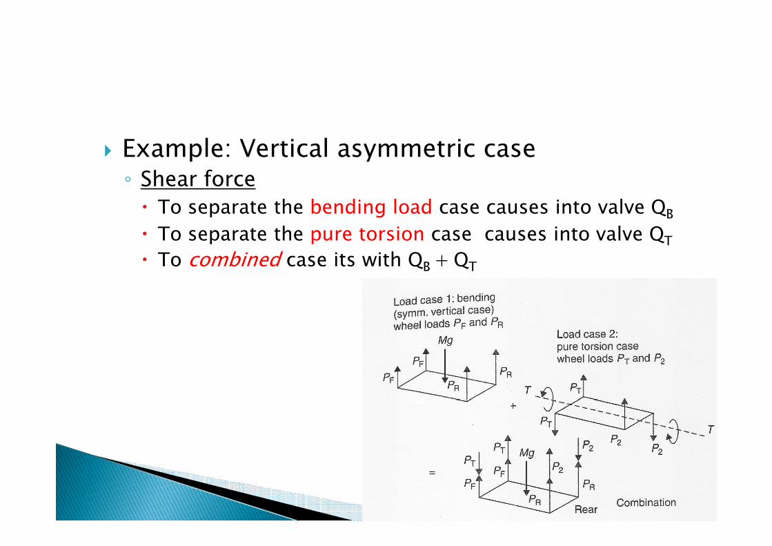
� Example: Vertical asymmetric case◦ Shear force
� To separate the bending load case causes into valve QB
� To separate the pure torsion case causes into valve QT
� To combined case its with QB +QTB T
Related Documents