5 205 Mechanics of Materials: Torsion of Shafts M. Vable Printed from: http://www.me.mtu.edu/~mavable/MoM2nd.htm September, 2011 CHAPTER FIVE TORSION OF SHAFTS Learning objectives 1. Understand the theory, its limitations, and its applications in design and analysis of torsion of circular shafts. 2. Visualize the direction of torsional shear stress and the surface on which it acts. _______________________________________________ When you ride a bicycle, you transfer power from your legs to the pedals, and through shaft and chain to the rear wheel. In a car, power is transferred from the engine to the wheel requiring many shafts that form the drive train such as shown in Figure 5.1a. A shaft also transfers torque to the rotor blades of a helicopter, as shown in Figure 5.1b. Lawn mowers, blenders, circular saws, drills— in fact, just about any equipment in which there is circular motion has shafts. Any structural member that transmits torque from one plane to another is called a shaft. This chapter develops the simplest theory for torsion in circular shafts, following the logic shown in Figure 3.15, but subject to the limitations described in Section 3.13. We then apply the formulas to the design and analysis of statically determinate and indeterminate shafts. 5.1 PRELUDE TO THEORY As a prelude to theory, we consider several numerical examples solved using the logic discussed in Section 3.2. Their solution will highlight conclusions and observations that will be formalized in the development of the theory in Section 5.2. • Example 5.1 shows the kinematics of shear strain in torsion. We apply the logic described in Figure 3.15, for the case of discrete bars attached to a rigid plate. • Examples 5.2 and 5.3 extend the of calculation of shear strain to continuous circular shafts. • Example 5.4 shows how the choice of a material model affects the calculation of internal torque. As we shall see the choice affects only the stress distribution, leaving all other equations unchanged. Thus the strain distribution, which is a kinematic relationship, is unaffected. So is static equivalency between shear stress and internal torque, and so are the equilibrium equations relating internal torques to external torques. Though we shall develop the simplest theory using Hooke’s law, most of the equations here apply to more complex models as well. (a) (b) Figure 5.1 Transfer of torques between planes.

Welcome message from author
This document is posted to help you gain knowledge. Please leave a comment to let me know what you think about it! Share it to your friends and learn new things together.
Transcript
5 205Mechanics of Materials: Torsion of ShaftsM. VablePr
inte
d fr
om: h
ttp://
ww
w.m
e.m
tu.e
du/~
mav
able
/MoM
2nd.
htm
CHAPTER FIVE
TORSION OF SHAFTS
Learning objectives
1. Understand the theory, its limitations, and its applications in design and analysis of torsion of circular shafts.2. Visualize the direction of torsional shear stress and the surface on which it acts.
_______________________________________________
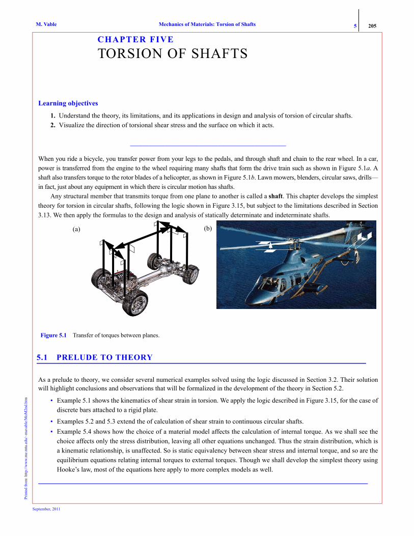
When you ride a bicycle, you transfer power from your legs to the pedals, and through shaft and chain to the rear wheel. In a car,power is transferred from the engine to the wheel requiring many shafts that form the drive train such as shown in Figure 5.1a. Ashaft also transfers torque to the rotor blades of a helicopter, as shown in Figure 5.1b. Lawn mowers, blenders, circular saws, drills—in fact, just about any equipment in which there is circular motion has shafts.
Any structural member that transmits torque from one plane to another is called a shaft. This chapter develops the simplesttheory for torsion in circular shafts, following the logic shown in Figure 3.15, but subject to the limitations described in Section3.13. We then apply the formulas to the design and analysis of statically determinate and indeterminate shafts.
5.1 PRELUDE TO THEORY
As a prelude to theory, we consider several numerical examples solved using the logic discussed in Section 3.2. Their solutionwill highlight conclusions and observations that will be formalized in the development of the theory in Section 5.2.
• Example 5.1 shows the kinematics of shear strain in torsion. We apply the logic described in Figure 3.15, for the case ofdiscrete bars attached to a rigid plate.
• Examples 5.2 and 5.3 extend the of calculation of shear strain to continuous circular shafts. • Example 5.4 shows how the choice of a material model affects the calculation of internal torque. As we shall see the
choice affects only the stress distribution, leaving all other equations unchanged. Thus the strain distribution, which isa kinematic relationship, is unaffected. So is static equivalency between shear stress and internal torque, and so are theequilibrium equations relating internal torques to external torques. Though we shall develop the simplest theory usingHooke’s law, most of the equations here apply to more complex models as well.
(a) (b)
Figure 5.1 Transfer of torques between planes.
September, 2011

5 206Mechanics of Materials: Torsion of ShaftsM. VablePr
inte
d fr
om: h
ttp://
ww
w.m
e.m
tu.e
du/~
mav
able
/MoM
2nd.
htm
EXAMPLE 5.1
The two thin bars of hard rubber shown in Figure 5.2 have shear modulus G = 280 MPa and cross-sectional area of 20 mm2. The bars areattached to a rigid disc of 20-mm radius. The rigid disc is observed to rotate about its axis by an angle of 0.04 rad due to the appliedtorque Text. Determine the applied torque Text.
PLANWe can relate the rotation (Δφ = 0.04) of the disc, the radius (r = 0.02 m) of the disc, and the length (0.2 m) of the bars to the shear strainin the bars as we did in Example 2.7. Using Hooke’s law, we can find the shear stress in each bar. By assuming uniform shear stress ineach bar, we can find the shear force. By drawing the free-body diagram of the rigid disc, we can find the applied torque Text.
SOLUTION1. Strain calculations: Figure 5.3 shows an approximate deformed shape of the two bars. By symmetry the shear strain in bar C will be
same as that in bar A. The shear strain in the bars can be calculated as in Example 2.7:
(E1)
(E2)
2. Stress calculations: From Hooke’s law we can find the shear stresses as
(E3)
(E4)3. Internal forces: We obtain the shear forces by multiplying the shear stresses by the cross-sectional area :
(E5)
(E6)
4. External torque: We draw the free-body diagram by making imaginary cuts through the bars, as shown in Figure 5.4. By equilibriumof moment about the axis of the disc through O, we obtain Equation (E7).
B
20 mm
C
A
T
200 mm
Figure 5.2 Geometry in Example 5.1.
ext
BB1 0.02 m( ) Δφ 0.0008 m= = γAtan γA≈BB1
AB---------- 0.004 rad==
γC γA 0.004 rad= =
D
B1
r ��
r ��
B
C
A
��
O
�A
E
Figure 5.3 Exaggerated deformed geometry: (a) 3-D; (b) Top view; (c) Side view.
(a)(b)
(c)
O
BB1
r
rΔφ
Δφ
B1B
A
γA
τA GAγA 280 106( ) N/m2[ ] 0.004( ) 1.12 106( ) N/m2= = =
τC GCγC 280 106( ) N/m2[ ] 0.004( ) 1.12 106( ) N/m2= = =
A 20 10 6–× m2=
VA AAτA 1.12 106( ) N/m2[ ] 20 10 6–( ) m2[ ] 22.4 N= = =
VC ACτC 1.12 106( ) N/m2[ ] 20 10 6–( ) m2[ ] 22.4 N= = =
VAVC
r � 0.02 m
r � 0.02 m
T
Figure 5.4 Free-body diagram: (a) 3-D; (b) Top view.
ext
O
Text
VA
VC
(a)(b)
r
September, 2011

5 207Mechanics of Materials: Torsion of ShaftsM. VablePr
inte
d fr
om: h
ttp://
ww
w.m
e.m
tu.e
du/~
mav
able
/MoM
2nd.
htm
(E7)ANS. Text = 0.896 N · m
COMMENTS1. In Figure 5.3 we approximated the arc BB1 by a straight line, and we approximated the tangent function by its argument in Equation (E1).
These approximations are valid only for small deformations and small strains. The net consequence of these approximations is that theshear strain along length AB1 is uniform, as can be seen by the angle between any vertical line and line AB1 at any point along the line.
2. The shear stress is assumed uniform across the cross section because of thin bars, but it is also uniform along the length because of theapproximations described in comment 1.
3. The shear stress acts on a surface with outward normal in the direction of the length of the bar, which is also the axis of the disc. Theshear force acts in the tangent direction to the circle of radius r. If we label the direction of the axis x, and the tangent direction θ, thenthe shear stress is represented by τxθ, as in Section 1.2
4. The sum in Equation (E7) can be rewritten as , where τ is the shear stress acting at the radius r, and ΔAi is the cross-sec-
tional area of the i th bar. If we had n bars attached to the disc at the same radius, then the total torque would be given by
As we increase the number of bars n to infinity, the assembly approaches a continuos body. The cross-sectional area ΔAi becomes theinfinitesimal area dA, and the summation is replaced by an integral. We will formalize the observations in Section 5.1.1.
5. In this example we visualized a circular shaft as an assembly of bars. The next two examples further develop this idea.
EXAMPLE 5.2
A rigid disc of 20-mm diameter is attached to a circular shaft made of hard rubber, as shown in Figure 5.5. The left end of the shaft isfixed into a rigid wall. The rigid disc was rotated counterclockwise by 3.25°. Determine the average shear strain at point A.
PLANWe can visualize the shaft as made up of infinitesimally thick bars of the type shown in Example 5.1. We relate the shear strain in the barto the rotation of the disc, as we did in Example 5.1.
SOLUTIONWe consider one line on the bar, as shown in Figure 5.6. Point B moves to point B1. The right angle between AB and AC changes, and thechange represents the shear strain γ. As in Example 5.1, we obtain the shear strain shown in Equation (E2):
(E1)
(E2)
ANS.
COMMENTS1. As in Example 5.1, we assumed that the line AB remains straight. If the assumption were not valid, then the shear strain would vary in
the axial direction.2. The change of right angle that is being measured by the shear strain is the angle between a line in the axial direction and the tangent at
any point. If we designate the axial direction x and the tangent direction θ (i.e., use polar coordinates), then the shear strain with sub-scripts will be γxθ.
Text rVA rVC+ 0.02 m( ) 22.4 N( ) 0.02 m( ) 22.4 N( )+= =
rτ ΔAii=1
2∑
rτ ΔAi .i=1
n∑
�� � 3.25�
200 mm
A
Figure 5.5 Geometry in Example 5.2.
Δφ 3.25°π180°
----------------- 0.05672 rad= = BB1 r Δφ 10 mm( ) Δφ 0.5672 mm= = =
γtan γBB1
AB---------- 0.5672 mm
200 mm---------------------------= 0.002836 rad= = =
γ 2836 μrad=
200 mm
A
C
B
B1
r � 10 mm
��
�
Figure 5.6 Deformed shape: (a) 3-D; (b) End view.
OB
B1
Δφ
r
rΔφ
(a) (b)
September, 2011

5 208Mechanics of Materials: Torsion of ShaftsM. VablePr
inte
d fr
om: h
ttp://
ww
w.m
e.m
tu.e
du/~
mav
able
/MoM
2nd.
htm
3. The value of the shear strain does not depend on the angular position as the problem is axisymmetric.4. If we start with a rectangular grid overlaid on the shaft, as shown in Figure 5.7a, then each rectangle will deform by the same amount,
as shown in Figure 5.7b. Based on the argument of axisymmetry, we will deduce this deformation for any circular shaft under torsionin the next section.
EXAMPLE 5.3
Three cylindrical shafts made from hard rubber are securely fastened to rigid discs, as shown in Figure 5.8. The radii of the shaft sectionsare rAB = 20 mm, rCD = 15 mm, and rEF = 10 mm. If the rigid discs are twisted by the angles shown, determine the average shear strain ineach section assuming the lines AB, CD, and EF remain straight.
METHOD 1: PLANEach section of the shaft will undergo the deformation pattern shown in Figure 5.6, but now we need to account for the rotation of thedisc at each end. We can analyze each section as we did in Example 5.2. In each section we can calculate the change of angle between thetangent and a line drawn in the axial direction at the point where we want to know the shear strain. We can then determine the sign of theshear strain using the definition of shear strain in Chapter 3.
SOLUTIONLabel the left most disc as disc 1 and the rightmost disc, disc 4. The rotation of each disc in radians is as follows:
(E1)
Figure 5.9 shows approximate deformed shapes of the three segments,
Using Figure 5.9a we can find the shear strain in AB as (E2)
(E3)
The shear strain is positive as the angle γAB represents a decrease of angle from right angle. ANS.
Using Figure 5.9b we can find the shear strain in CD as
Figure 5.7 Deformation in torsion of (a) an un-deformed shaft. (b) a deformed shaft.
(a) (b)
200 mm 160 mm120 mm
2.5�1.5�
1.5�3.25�
A B C D E F
Figure 5.8 Shaft geometry in Example 5.3.
φ12.5°
180°----------- 3.142 rad( ) 0.0436 rad= = φ2
1.5°
180°----------- 3.142 rad( ) 0.0262 rad= =
φ31.5°
180°----------- 3.142 rad( ) 0.0262 rad= = φ4
3.25°
180°------------ 3.142 rad( ) 0.0567 rad= =
200 mm
AB
B1
A1�AB
�AB
Figure 5.9 Approximate deformed shapes for Method 1 in Example 5.3 of segments (a) AB, (b) CD, and (c) EF.
B1
B
C1
CD
160 mm
�CD
�CD
D1
F
120 mm
�EFE1
ED
D1�EF
F1(a) (b) (c)
AA1 rABφ1 20 mm( ) 0.0436( ) 0.872 mm= = = BB1 rABφ2 20 mm( ) 0.0262( ) 0.524 mm= = =
γABtan γAB≈AA1 BB1+
AB-------------------------- 0.872 mm 0.524 mm+
200 mm--------------------------------------------------------= =
γAB 6980 μrad=
September, 2011
5 209Mechanics of Materials: Torsion of ShaftsM. VablePr
inte
d fr
om: h
ttp://
ww
w.m
e.m
tu.e
du/~
mav
able
/MoM
2nd.
htm
(E4)
(E5)
The shear strain is negative as the angle γCD represents an increase of angle from right angle.ANS.
Using Figure 5.9c we can find the shear strain in EF as (E6)
(E7)
The shear strain is negative as the angle γEF represents an increase of angle from right angle.ANS.
METHOD 2: PLAN We assign a sign to the direction of rotation, calculate the relative deformation of the right disc with respect to the left disc, and analyzethe entire shaft.
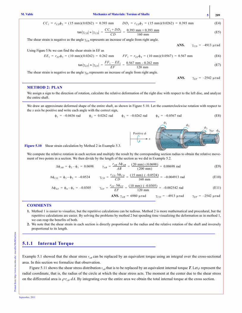
We draw an approximate deformed shape of the entire shaft, as shown in Figure 5.10. Let the counterclockwise rotation with respect tothe x axis be positive and write each angle with the correct sign,
(E8)
We compute the relative rotation in each section and multiply the result by the corresponding section radius to obtain the relative move-ment of two points in a section. We then divide by the length of the section as we did in Example 5.2.
(E9)
(E10)
(E11)
ANS.
COMMENTS1. Method 1 is easier to visualize, but the repetitive calculations can be tedious. Method 2 is more mathematical and procedural, but the
repetitive calculations are easier. By solving the problems by method 2 but spending time visualizing the deformation as in method 1,we can reap the benefits of both.
2. We note that the shear strain in each section is directly proportional to the radius and the relative rotation of the shaft and inverselyproportional to its length.
5.1.1 Internal Torque
Example 5.1 showed that the shear stress τxθ can be replaced by an equivalent torque using an integral over the cross-sectionalarea. In this section we formalize that observation.
Figure 5.11 shows the shear stress distribution τxθ that is to be replaced by an equivalent internal torque T. Let ρ represent theradial coordinate, that is, the radius of the circle at which the shear stress acts. The moment at the center due to the shear stresson the differential area is . By integrating over the entire area we obtain the total internal torque at the cross section.
CC1 rCDφ2 15 mm( ) 0.0262( ) 0.393 mm= = = DD1 rCDφ3 15 mm( ) 0.0262( ) 0.393 mm= = =
γCDtan γCD≈CC1 DD1+
CD---------------------------- 0.393 mm 0.393 mm+
160 mm--------------------------------------------------------= =
γCD 4913– μrad=
EE1 rEFφ3 10 mm( ) 0.0262( ) 0.262 mm= = = FF1 rEFφ4 10 mm( ) 0.0567( ) 0.567 mm= = =
γEFtan γEF≈FF1 E– E1
EF--------------------------- 0.567 mm 0.262 mm–
120 mm-------------------------------------------------------= =
γEF 2542– μrad=
φ1 0.0436– rad= φ2 0.0262 rad= φ3 0.0262– rad= φ4 0.0567– rad=
�EFPositive �
x
�1�2
A1
B1C1
D1�AB
�CD
A B C D
�3�4
E F
Figure 5.10 Shear strain calculation by Method 2 in Example 5.3.
ΔφAB φ2 φ1– 0.0698= = γABrAB ΔφAB
AB----------------------- 20 mm( ) 0.0698( )
200 mm( )--------------------------------------------- 0.00698 rad= = =
ΔφCD φ3 φ2– 0.0524–= = γCDrCD ΔφCD
CD------------------------ 15 mm( ) 0.0524–( )
160 mm------------------------------------------------- 0.004913 rad–= = =
ΔφEF φ4 φ3– 0.0305–= = γEFrEF ΔφEF
EF----------------------- 10 mm( ) 0.0305–( )
120 mm------------------------------------------------- 0.002542 rad–= = =
γAB 6980 μrad= γCD 4913 μrad–= γEF 2542 μrad–=
ρτxθ dA
September, 2011

5 210Mechanics of Materials: Torsion of ShaftsM. VablePr
inte
d fr
om: h
ttp://
ww
w.m
e.m
tu.e
du/~
mav
able
/MoM
2nd.
htm
(5.1)
Equation (5.1) is independent of the material model as it represents static equivalency between the shear stress on the entirecross section and the internal torque. If we were to consider a composite shaft cross section or nonlinear material behavior, thenit would affect the value and distribution of τxθ across the cross section. But Equation (5.1), relating τxθ and T, would remainunchanged. Examples 5.4 will clarify the discussion in this paragraph.
EXAMPLE 5.4
A homogeneous cross section made of brass and a composite cross section of brass and steel are shown in Figure 5.12. The shear moduliof elasticity for brass and steel are GB = 40 GPa and GS = 80 GPa, respectively. The shear strain in polar coordinates at the cross sectionwas found to be , where ρ is in meters. (a)Write expressions for τxθ as a function of ρ and plot the shear strain and shearstress distributions across both cross sections. (b) For each of the cross sections determine the statically equivalent internal torques.
PLAN(a) Using Hooke’s law we can find the shear stress distribution as a function of ρ in each material. (b) Each of the shear stress distribu-tions can be substituted into Equation (5.1) and the equivalent internal torque obtained by integration.
SOLUTION(a) From Hooke’s law we can write the stresses as
(E1)
(E2)
For the homogeneous cross section the stress distribution is as given in Equation (E1), but for the composite section it switches betweenEquation (E2) and Equation (E1), depending on the value of ρ. We can write the shear stress distribution for both cross sections as afunction of ρ, as shown below.Homogeneous cross section:
(E3)
T ρ VdA
∫ ρτxθ AdA
∫= =
x
�dV � �x� dAT
Figure 5.11 Statically equivalent internal torque.
γxθ 0.08ρ=
�
120 mm 80 mm
120 mm
x
�
�
x
�
Figure 5.12 Homogeneous and composite cross sections in Example 5.4.
τxθ( )brass 40 109( ) N/m2[ ] 0.08ρ( ) 3200ρ MPa= =
τxθ( )steel 80 109( ) N/m2[ ] 0.08ρ( ) 6400ρ MPa= =
τxθ 3200ρ MPa 0.00 ρ 0.06<≤=
�
�x�� � ()
44
(a)
�
�x� � (MPa)
2566
(c)
�
�x� � (MPa)
(b)
Figure 5.13 Shear strain and shear stress distributions in Example 5.4: (a) shear strain distribution; (b) shear stress distri-bution in homogeneous cross section; (c) shear stress distribution in composite cross section.
September, 2011

5 211Mechanics of Materials: Torsion of ShaftsM. VablePr
inte
d fr
om: h
ttp://
ww
w.m
e.m
tu.e
du/~
mav
able
/MoM
2nd.
htm
Composite cross section:
(E4)
The shear strain and the shear stress can now be plotted as a function of ρ, as shown in Figure 5.13(b). The differential area dA is the areaof a ring of radius ρ and thickness dρ, that is, . Equation (5.1) can be written as
(E5)
Homogeneous cross section: Substituting Equation (E3) into Equation (E5) and integrating, we obtain the equivalent internal torque.
(E6)
ANS.Composite cross section: Writing the integral in Equation (E5) as a sum of two integrals and substituting Equation (E3) we obtain theequivalent internal torque.
(E7)
(E8)
(E9)
(E10)
ANS.
COMMENTS1. The example demonstrates that although the shear strain varies linearly across the cross section, the shear stress may not. In this
example we considered material non homogeneity. In a similar manner we can consider other models, such as elastic–perfectly plas-tic, or material models that have nonlinear stress–strain curves.
2. The material models dictate the shear stress distribution across the cross section, but once the stress distribution is known, Equation(5.1) can be used to find the equivalent internal torque, emphasizing that Equation (5.1) does not depend on the material model.
PROBLEM SET 5.1
5.1 A pair of 48-in. long bars and a pair of 60-in. long bars are symmetrically attached to a rigid disc at a radius of 2 in. at one end andbuilt into the wall at the other end, as shown in Figure P5.1. The shear strain at point A due to a twist of the rigid disc was found to be 3000μrad. Determine the magnitude of shear strain at point D.
5.2 If the four bars in Problem 5.1 are made from a material that has a shear modulus of 12,000 ksi, determine the applied torque T on therigid disc. The cross sectional areas of all bars are 0.25 in.2.
5.3 If bars AB in Problem 5.1 are made of aluminum with a shear modulus Gal = 4000 ksi and bars CD are made of bronze with a shearmodulus Gbr = 6500 ksi, determine the applied torque T on the rigid disc. The cross-sectional areas of all bars are 0.25 in.2.
τxθ6400ρ MPa 0.00 ρ 0.04 m<≤
3200ρ MPa 0.04 m ρ< 0.06 m≤⎩⎨⎧
=
dA 2πρ dρ=
T ρτxθ 2πρ dρ( )0
0.06
∫=
T ρ 3200ρ 106( ) [ ] 2πρ dρ( )0
0.06
∫ 6400π 106( )[ ]ρ4
4-----⎝ ⎠
⎛ ⎞0
0.06
65.1 103( ) N m⋅= = =
T 65.1= kN·m
T ρτxθ 2πρ dρ( )0
0.06
∫ ρτxθ 2πρ dρ( )0
0.04
∫ ρτxθ 2πρ dρ( )0.04
0.06
∫+= =
⎧ ⎪ ⎪ ⎪ ⎨ ⎪ ⎪ ⎪ ⎩ ⎧ ⎪ ⎪ ⎪ ⎨ ⎪ ⎪ ⎪ ⎩
Tsteel Tbrass
Tsteel ρ 6400ρ 106( )[ ] 2πρ dρ( ) 12800π( ) 106( ) ρ4
4-----⎝ ⎠
⎛ ⎞=0
0.04
0
0.04
∫ 25.7 103( ) N m⋅ 25.7 kN·m= = =
Tbrass ρ 3200ρ 106( )[ ] 2πρ dρ( ) 6400π( )= 106( ) ρ4
4-----⎝ ⎠
⎛ ⎞0.04
0.06
0.04
0.06
∫ 52.3 103( ) N m⋅ 52.3 kN·m= = =
T Tsteel Tbrass+ 25.7 kN·m 52.3 kN·m+= =
T 78 kN·m=
B
T
48 in 60 in
C
Figure P5.1
September, 2011

5 212Mechanics of Materials: Torsion of ShaftsM. VablePr
inte
d fr
om: h
ttp://
ww
w.m
e.m
tu.e
du/~
mav
able
/MoM
2nd.
htm
5.4 Three pairs of bars are symmetrically attached to rigid discs at the radii shown in Figure P5.4. The discs were observed to rotate byangles and in the direction of the applied torques T1, T2, and T3, respectively. The shear modulus of the
bars is 40 ksi and cross-sectional area is 0.04 in.2. Determine the applied torques.
5.5 A circular shaft of radius r and length Δx has two rigid discs attached at each end, as shown in Figure P5.5. If the rigid discs arerotated as shown, determine the shear strain γ at point A in terms of r, Δx, and Δφ, assuming that line AB remains straight, where
5.6 A hollow circular shaft made from hard rubber has an outer diameter of 4 in and an inner diameter of 1.5 in. The shaft is fixed to thewall on the left end and the rigid disc on the right hand is twisted, as shown in Figure P5.6. The shear strain at point A, which is on the out-side surface, was found to be 4000 μrad. Determine the shear strain at point C, which is on the inside surface, and the angle of rotation.Assume that lines AB and CD remain straight during deformation.
5.7 The magnitude of shear strains in the segments of the stepped shaft in Figure P5.7 was found to be γAB = 3000 μrad, γCD = 2500 μrad,and γEF = 6000 μrad. The radius of section AB is 150 mm, of section CD 70 mm, and of section EF 60 mm.Determine the angle by whicheach of the rigid discs was rotated.
5.8 Figure P5.8 shows the cross section of a hollow aluminum (G= 26 GPa) shaft. The shear strain γxθ in polar coordinates at the sectionis , where ρ is in meters. Determine the equivalent internal torque acting at the cross-section. Use di= 30 mm and do = 50 mm.
φ1 1.5° ,= φ2 3.0° ,= φ3 2.5°=
B
BC
T2TTT3TT
T1
40 in25 in 30 in
C
D
DF
E F
1.5 in
Figure P5.4
Δφ φ2 φ1.–=
�x
�2�1
Figure P5.5
36 in
�
Figure P5.6
�1
�3�2
2 m 1.8 m 1.2 m Figure P5.7
γxθ 0.06ρ–=
do
di
x
θρ
Figure P5.8
September, 2011

5 213Mechanics of Materials: Torsion of ShaftsM. VablePr
inte
d fr
om: h
ttp://
ww
w.m
e.m
tu.e
du/~
mav
able
/MoM
2nd.
htm
5.9 Figure P5.8 shows the cross section of a hollow aluminum (G = 26 GPa) shaft. The shear strain γxθ in polar coordinates at the sectionis , where ρ is in meters. Determine the equivalent internal torque acting at the cross-section. Use di= 40 mm and do = 120 mm.
5.10 A hollow brass shaft (GB = 6500 ksi) and a solid steel shaft (GS = 13,000 ksi) are securely fastened to form a composite shaft, asshown in Figure P5.10.The shear strain in polar coordinates at the section is , where ρ is in inches. Determine the equivalentinternal torque acting at the cross section. Use dB = 4 in. and dS = 2 in.
5.11 A hollow brass shaft (GB = 6500 ksi) and a solid steel shaft (GS = 13,000 ksi) are securely fastened to form a composite shaft, asshown in Figure P5.10.The shear strain in polar coordinates at the section is , where ρ is in inches. Determine the equiva-lent internal torque acting at the cross section. Use dB = 6 in. and dS = 4 in.
5.12 A hollow brass shaft (GB = 6500 ksi) and a solid steel shaft (GS = 13,000 ksi) are securely fastened to form a composite shaft, asshown in Figure P5.10.The shear strain in polar coordinates at the section is , where ρ is in inches. Determine the equivalentinternal torque acting at the cross section. Use dB = 3 in. and dS = 1 in.
5.13 A hollow titanium shaft (GTi = 36 GPa) and a hollow aluminum shaft (GAl = 26 GPa) are securely fastened to form a compositeshaft shown in Figure P5.13. The shear strain in polar coordinates at the section is where ρ is in meters. Determine the equiv-alent internal torque acting at the cross section. Use di = 50 mm, dAl = 90 mm, and dTi = 100 mm.
Stretch Yourself5.14 A circular shaft made from elastic - perfectly plastic material has a torsional shear stress distribution across the cross section shownin Figure P5.14. Determine the equivalent internal torque.
5.15 A solid circular shaft of 3-in. diameter has a shear strain at a section in polar coordinates of γxθ = 2ρ (10-3), where ρ is the radial coor-dinate measured in inches. The shaft is made from an elastic–perfectly plastic material, which has a yield stress τyield = 18 ksi and a shearmodulus G = 12,000 ksi. Determine the equivalent internal torque. (See Problem 3.144).
γxθ 0.05ρ=
γxθ 0.001ρ=
Figure P5.10dB
dS
x
θ
ρ
Brass
Steel
γxθ 0.0005ρ–=
γxθ 0.002ρ=
γxθ 0.04ρ ,=
Figure P5.13
d Ti
d Al
x
θ
d i
Titanium Aluminum
ρ
τxθ
ρ
24 ksi
0.3 in. Figure P5.14 0.3 in.
September, 2011

5 214Mechanics of Materials: Torsion of ShaftsM. VablePr
inte
d fr
om: h
ttp://
ww
w.m
e.m
tu.e
du/~
mav
able
/MoM
2nd.
htm
5.16 A solid circular shaft of 3-in. diameter has a shear strain at a section in polar coordinates of γxθ = 2ρ (10-3), where ρ is the radial coor-dinate measured in inches.The shaft is made form a bilinear material as shown in Figure 3.40. The material has a yield stress τyield = 18 ksiand shear moduli G1 = 12,000 ksi and G2 = 4800 ksi. Determine the equivalent internal torque.(See Problem 3.145).
5.17 A solid circular shaft of 3-in. diameter has a shear strain at a section in polar coordinates of γxθ = 2ρ (10-3), where ρ is the radial coor-dinate measured in inches.The shaft material has a stress–strain relationship given by τ = 243γ 0 .4 ksi. Determine the equivalent internaltorque. (See Problem 3.146).
5.18 A solid circular shaft of 3-in diameter has a shear strain at a section in polar coordinates of γxθ = 2ρ (10-3), where ρ is the radial coor-dinate measured in inches. The shaft material has a stress–strain relationship given by τ = 12,000γ − 120,000γ2 ksi. Determine the equiva-lent internal torque. (See Problem 3.147).
5.2 THEORY OF TORSION OF CIRCULAR SHAFTS
In this section we develop formulas for deformation and stress in a circular shaft. We will follow the procedure in Section 5.1but now with variables in place of numbers. The theory will be developed subject to the following limitations:
1. The length of the member is significantly greater than the greatest dimension in the cross section.2. We are away from the regions of stress concentration. 3. The variation of external torque or change in cross-sectional areas is gradual except in regions of stress concentration. 4. External torques are not functions of time; that is, we have a static problem. (See Problems 5.55 and 5.56 for dynamic
problems.)5. The cross section is circular. This permits us to use arguments of axisymmetry in deducing deformation.
Figure 5.14 shows a circular shaft that is loaded by external torques T1 and T2 at each end and an external distributed torquet(x), which has units of torque per unit length. The radius of the shaft R(x) varies as a function of x. We expect that the internaltorque T will be a function of x. φ1 and φ2 are the angles of rotation of the imaginary cross sections at x1 and x2, respectively.
The objectives of the theory are:
1. To obtain a formula for the relative rotation φ2 – φ1 in terms of the internal torque T.2. To obtain a formula for the shear stress τxθ in terms of the internal torque T.
To account for the variations in t(x) and R(x) we will take Δx = x2 − x1 as an infinitesimal distance in which these quantitiescan be treated as constants. The deformation behavior across the cross section will be approximated. The logic shown in Figure5.15 and discussed in Section 3.2 will be used to develop the simplest theory for the torsion of circular shafts members. Assump-tions will be identified as we move from one step to the next. These assumptions are the points at which complexities can beadded to the theory, as discussed in the examples and Stretch Yourself problems.
Figure 5.14 Circular shaft.
T2TT
x2
x
z
y
r �
September, 2011
5 215Mechanics of Materials: Torsion of ShaftsM. VablePr
inte
d fr
om: h
ttp://
ww
w.m
e.m
tu.e
du/~
mav
able
/MoM
2nd.
htm
5.2.1 Kinematics
In Example 5.1 the shear strain in a bar was related to the rotation of the disc that was attached to it. In Example 5.2 we remarkedthat a shaft could be viewed as an assembly of bars. Three assumptions let us simulate the behavior of a cross section as a rotat-ing rigid plate:
Assumption 1 Plane sections perpendicular to the axis remain plane during deformation.
Assumption 2 On a cross section, all radial lines rotate by equal angles during deformation.
Assumption 3 Radial lines remain straight during deformation.
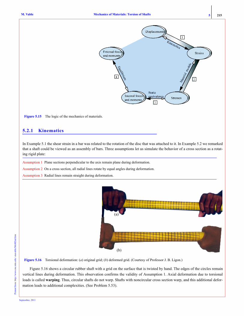
Figure 5.16 shows a circular rubber shaft with a grid on the surface that is twisted by hand. The edges of the circles remainvertical lines during deformation. This observation confirms the validity of Assumption 1. Axial deformation due to torsionalloads is called warping. Thus, circular shafts do not warp. Shafts with noncircular cross section warp, and this additional defor-mation leads to additional complexities. (See Problem 5.53).
Figure 5.15 The logic of the mechanics of materials.
Figure 5.16 Torsional deformation: (a) original grid; (b) deformed grid. (Courtesy of Professor J. B. Ligon.)
(a)
(b)
September, 2011

5 216Mechanics of Materials: Torsion of ShaftsM. VablePr
inte
d fr
om: h
ttp://
ww
w.m
e.m
tu.e
du/~
mav
able
/MoM
2nd.
htm
The axisymmetry of the problem implies that deformation must be independent of the angular rotation. Thus, all radialslines must behave in exactly the same manner irrespective of their angular position, thus, Assumptions 2 and 3 are valid for cir-cular shafts. Figure 5.17 shows that all radial lines rotate by the same angle of twist φ. We note that if all lines rotate by equalamounts on the cross section, then φ does not change across the cross section and hence can only be a function of x
(5.2)Sign Convention: φ is considered positive counterclockwise with respect to the x axis.
The shear strain of interest to us is the measure of the angle change between the axial direction and the tangent to the circlein Figure 5.16. If we use polar coordinates, then we are interested in the change in angle which is between the x and θ direc-tions— in other words, γxθ.
Assumptions 1 through 3 are analogous to viewing each cross section in the shaft as a rigid disc that rotates about its ownaxis. We can then calculate the shear strain as in Example 5.2, provided we have small deformation and strain.
Assumption 4 Strains are small.
We consider a shaft with radius ρ and length Δx in which the right section with respect to the left section is rotated by an angleΔφ, as shown in Figure 5.18a. Using geometry we obtain the shear strain expression.
or
(5.3)
where ρ is the radial coordinate of a point on the cross section. The subscripts x and θ emphasize that the change in angle isbetween the axial and tangent directions, as shown in Figure 5.18a. The quantity is called the rate of twist. It is a func-tion of x only, because φ is a function of x only.
Equation (5.3) was derived from purely geometric considerations. If Assumptions 1 through 4 are valid, then Equation (5.3)is independent of the material. Equation (5.3) shows that the shear strain is a linear function of the radial coordinate ρ andreaches the maximum value γmax at the outer surface (ρ = ρmax = R), as shown in Figure 5.18a. Equation (5.4), an alternativeform for shear strain, can be derived using similar triangles.
(5.4)
5.2.2 Material Model
Our motivation is to develop a simple theory for torsion of circular shafts. Thus we make assumptions regarding material behav-ior that will permit us to use the simplest material model given by Hooke’s law.
φ φ x( )=
������ �
Figure 5.17 Equal rotation of all radial lines.
A1
B1AoBoAo,Bo —Initial position
A1,B1 —Deformed position
�
�x
z
y
�
Figure 5.18 Shear strain in torsion. (a) Deformed shape. (b) Linear variation of shear strain.
�x�� �
�x�� �
�max��
R
��
(a) (b)
γxθ γxθ≈tan AB 0→lim
BB1
AB---------⎝ ⎠
⎛ ⎞ Δx 0→lim ρΔφ
Δx----------⎝ ⎠
⎛ ⎞= =
γxθ ρxd
dφ=
dφ d⁄ x
γxθγmaxρ
R-------------=
September, 2011
5 217Mechanics of Materials: Torsion of ShaftsM. VablePr
inte
d fr
om: h
ttp://
ww
w.m
e.m
tu.e
du/~
mav
able
/MoM
2nd.
htm
Assumption 5 The material is linearly elastic.1
Assumption 6 The material is isotropic.
Substituting Equation (5.3) into Hooke’s law, that is, we obtain
(5.5)
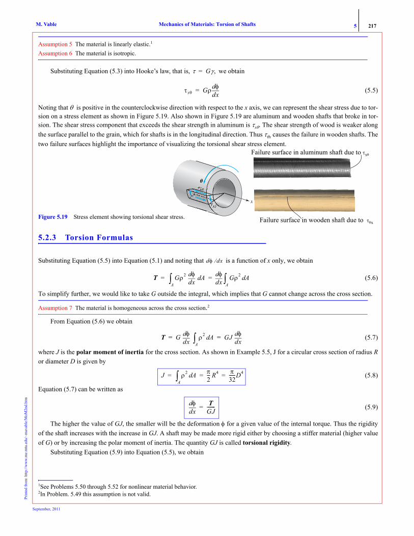
Noting that θ is positive in the counterclockwise direction with respect to the x axis, we can represent the shear stress due to tor-sion on a stress element as shown in Figure 5.19. Also shown in Figure 5.19 are aluminum and wooden shafts that broke in tor-sion. The shear stress component that exceeds the shear strength in aluminum is τxθ. The shear strength of wood is weaker alongthe surface parallel to the grain, which for shafts is in the longitudinal direction. Thus τθx causes the failure in wooden shafts. Thetwo failure surfaces highlight the importance of visualizing the torsional shear stress element.
5.2.3 Torsion Formulas
Substituting Equation (5.5) into Equation (5.1) and noting that is a function of x only, we obtain
(5.6)
To simplify further, we would like to take G outside the integral, which implies that G cannot change across the cross section.
Assumption 7 The material is homogeneous across the cross section.2
From Equation (5.6) we obtain
(5.7)
where J is the polar moment of inertia for the cross section. As shown in Example 5.5, J for a circular cross section of radius Ror diameter D is given by
(5.8)
Equation (5.7) can be written as
(5.9)
The higher the value of GJ, the smaller will be the deformation φ for a given value of the internal torque. Thus the rigidityof the shaft increases with the increase in GJ. A shaft may be made more rigid either by choosing a stiffer material (higher valueof G) or by increasing the polar moment of inertia. The quantity GJ is called torsional rigidity.
Substituting Equation (5.9) into Equation (5.5), we obtain
1See Problems 5.50 through 5.52 for nonlinear material behavior.2In Problem. 5.49 this assumption is not valid.
τ Gγ,=
τxθ Gρxd
dφ=
Failure surface in wooden shaft due to ��� x
Failure surface in aluminum shaft due to �x� �
x
Failure surface in wooden shaft due to τθxFigure 5.19 Stress element showing torsional shear stress.
Failure surface in aluminum shaft due to τxθ
dφ dx⁄
T Gρ2 xd
dφA
∫ Adxd
dφ Gρ2 AdA
∫= =
T G xd
dφ ρ2 AdA
∫ GJ xd
dφ= =
J ρ2 AdA
∫π2--- R4 π
32------D4= = =
xddφ T
GJ-------=
September, 2011
5 218Mechanics of Materials: Torsion of ShaftsM. VablePr
inte
d fr
om: h
ttp://
ww
w.m
e.m
tu.e
du/~
mav
able
/MoM
2nd.
htm
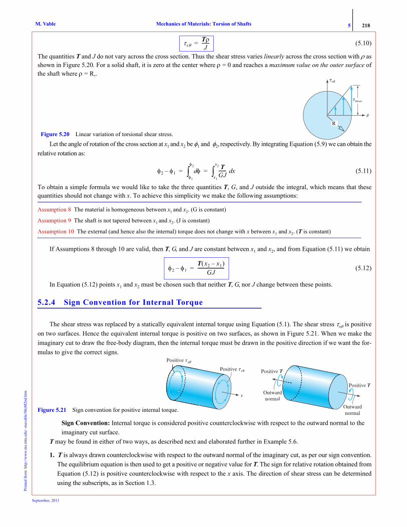
(5.10)
The quantities T and J do not vary across the cross section. Thus the shear stress varies linearly across the cross section with ρ asshown in Figure 5.20. For a solid shaft, it is zero at the center where ρ = 0 and reaches a maximum value on the outer surface ofthe shaft where ρ = R,.
Let the angle of rotation of the cross section at x1 and x2 be φ1 and φ2, respectively. By integrating Equation (5.9) we can obtain therelative rotation as:
(5.11)
To obtain a simple formula we would like to take the three quantities T, G, and J outside the integral, which means that thesequantities should not change with x. To achieve this simplicity we make the following assumptions:
Assumption 8 The material is homogeneous between x1 and x2. (G is constant)
Assumption 9 The shaft is not tapered between x1 and x2. (J is constant)
Assumption 10 The external (and hence also the internal) torque does not change with x between x1 and x2. (T is constant)
If Assumptions 8 through 10 are valid, then T, G, and J are constant between x1 and x2, and from Equation (5.11) we obtain
(5.12)
In Equation (5.12) points x1 and x2 must be chosen such that neither T, G, nor J change between these points.
5.2.4 Sign Convention for Internal Torque
The shear stress was replaced by a statically equivalent internal torque using Equation (5.1). The shear stress τxθ is positiveon two surfaces. Hence the equivalent internal torque is positive on two surfaces, as shown in Figure 5.21. When we make theimaginary cut to draw the free-body diagram, then the internal torque must be drawn in the positive direction if we want the for-mulas to give the correct signs.
Sign Convention: Internal torque is considered positive counterclockwise with respect to the outward normal to the imaginary cut surface.
T may be found in either of two ways, as described next and elaborated further in Example 5.6.
1. T is always drawn counterclockwise with respect to the outward normal of the imaginary cut, as per our sign convention.The equilibrium equation is then used to get a positive or negative value for T. The sign for relative rotation obtained fromEquation (5.12) is positive counterclockwise with respect to the x axis. The direction of shear stress can be determinedusing the subscripts, as in Section 1.3.
τxθTρJ
-------=
�x�� �
�
�max��
Figure 5.20 Linear variation of torsional shear stress.
R
φ2 φ1– φdφ1
φ2
∫T
GJ------- xd
x1
x2
∫= =
φ2 φ1–T x2 x1–( )
GJ------------------------=
x
Positive �x� �
Outwardnormal
Outwardnormal
Positive �x� �
Positive T
Positive T
Figure 5.21 Sign convention for positive internal torque.
September, 2011
5 219Mechanics of Materials: Torsion of ShaftsM. VablePr
inte
d fr
om: h
ttp://
ww
w.m
e.m
tu.e
du/~
mav
able
/MoM
2nd.
htm
2. T is drawn at the imaginary cut to equilibrate the external torques. Since inspection is used to determine the directionof T, the direction of relative rotation in Equation (5.12) and the direction of shear stress τxθ in Equation (5.10) mustalso be determined by inspection.
5.2.5 Direction of Torsional Stresses by Inspection.
The significant shear stress in the torsion of circular shafts is τxθ. All other stress components can be neglected provided the ratioof the length of the shaft to its diameter is on the order of 10 or more.
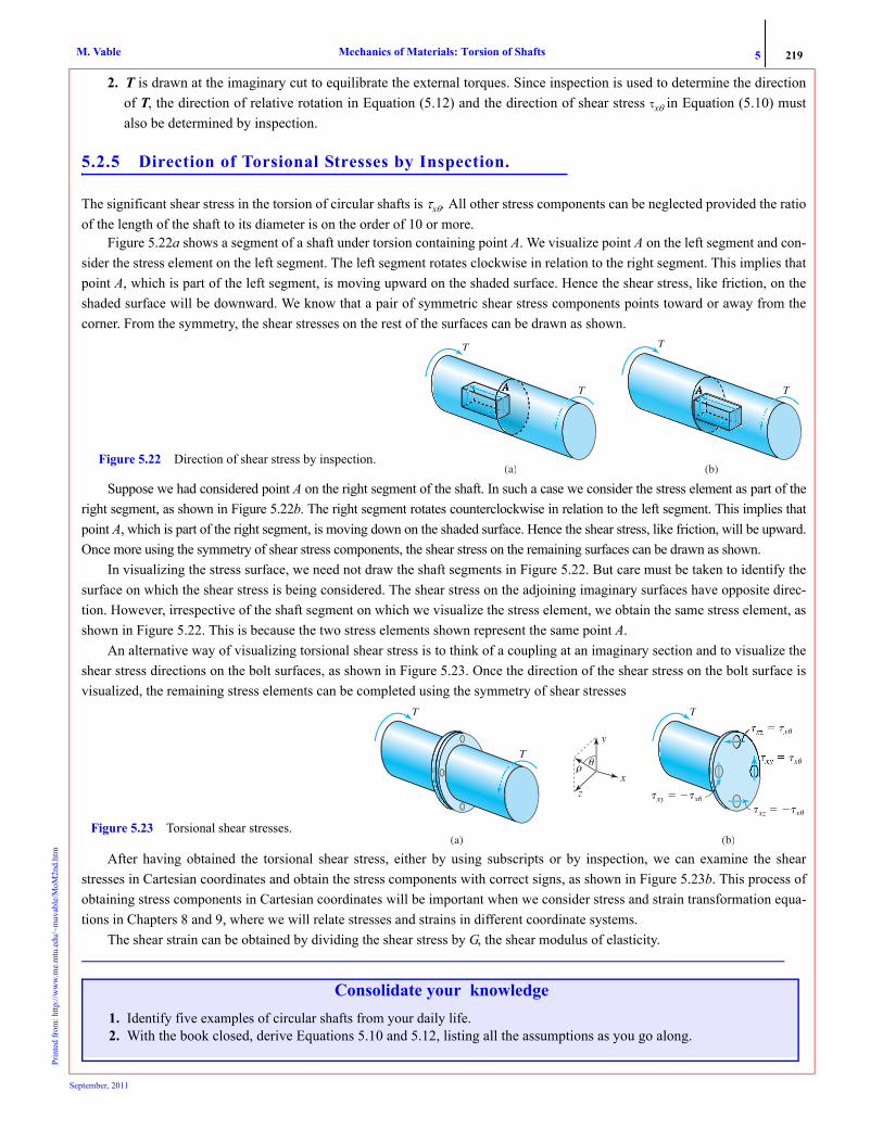
Figure 5.22a shows a segment of a shaft under torsion containing point A. We visualize point A on the left segment and con-sider the stress element on the left segment. The left segment rotates clockwise in relation to the right segment. This implies thatpoint A, which is part of the left segment, is moving upward on the shaded surface. Hence the shear stress, like friction, on theshaded surface will be downward. We know that a pair of symmetric shear stress components points toward or away from thecorner. From the symmetry, the shear stresses on the rest of the surfaces can be drawn as shown.
Suppose we had considered point A on the right segment of the shaft. In such a case we consider the stress element as part of theright segment, as shown in Figure 5.22b. The right segment rotates counterclockwise in relation to the left segment. This implies thatpoint A, which is part of the right segment, is moving down on the shaded surface. Hence the shear stress, like friction, will be upward.Once more using the symmetry of shear stress components, the shear stress on the remaining surfaces can be drawn as shown.
In visualizing the stress surface, we need not draw the shaft segments in Figure 5.22. But care must be taken to identify thesurface on which the shear stress is being considered. The shear stress on the adjoining imaginary surfaces have opposite direc-tion. However, irrespective of the shaft segment on which we visualize the stress element, we obtain the same stress element, asshown in Figure 5.22. This is because the two stress elements shown represent the same point A.
An alternative way of visualizing torsional shear stress is to think of a coupling at an imaginary section and to visualize theshear stress directions on the bolt surfaces, as shown in Figure 5.23. Once the direction of the shear stress on the bolt surface isvisualized, the remaining stress elements can be completed using the symmetry of shear stresses
After having obtained the torsional shear stress, either by using subscripts or by inspection, we can examine the shearstresses in Cartesian coordinates and obtain the stress components with correct signs, as shown in Figure 5.23b. This process ofobtaining stress components in Cartesian coordinates will be important when we consider stress and strain transformation equa-tions in Chapters 8 and 9, where we will relate stresses and strains in different coordinate systems.
The shear strain can be obtained by dividing the shear stress by G, the shear modulus of elasticity.
(a)
T
T
(b)
T
T
Figure 5.22 Direction of shear stress by inspection.
(a) (b)
T
T
zx
y
���
T
�xy� � ��x� �
� � �x� �
�x� �
�xz� � ��x� �
Figure 5.23 Torsional shear stresses.
Consolidate your knowledge1. Identify five examples of circular shafts from your daily life.2. With the book closed, derive Equations 5.10 and 5.12, listing all the assumptions as you go along.
September, 2011

5 220Mechanics of Materials: Torsion of ShaftsM. VablePr
inte
d fr
om: h
ttp://
ww
w.m
e.m
tu.e
du/~
mav
able
/MoM
2nd.
htm
EXAMPLE 5.5
The two shafts shown in Figure 5.24 are of the same material and have the same amount of material cross-sectional areas A. Show thatthe hollow shaft has a larger polar moment of inertia than the solid shaft.
PLANWe can find the values of RH and RS in terms of the cross-sectional area A. We can then substitute these radii in the formulas for polararea moment to obtain the polar area moments in terms of A.
SOLUTIONWe can calculate the radii RH and RS in terms of the cross sectional area A as
(E1)
The polar area moment of inertia for a hollow shaft with inside radius Ri and outside radius Ro can be obtained as
(E2)
For the hollow shaft Ro = 2RH and Ri = RH, whereas for the solid shaft Ro = RS and Ri = 0. Substituting these values into Equation (E2), weobtain the two polar area moments.
(E3)
Dividing JH by JS we obtain
(E4)
ANS. As the polar moment for the hollow shaft is greater than that of the solid shaft for the same amount of material.
COMMENT1. The hollow shaft has a polar moment of inertia of 1.67 times that of the solid shaft for the same amount of material. Alternatively, a
hollow shaft will require less material (lighter in weight) to obtain the same polar moment of inertia. This reduction in weight is theprimary reason why metal shafts are made hollow. Wooden shafts, however, are usually solid as the machining cost does not justifythe small saving in weight.
EXAMPLE 5.6 A solid circular steel shaft (Gs = 12,000 ksi) of variable diameter is acted upon by torques as shown in Figure 5.25. The diameter of theshaft between wheels A and B and wheels C and D is 2 in., and the diameter of the shaft between wheels B and C is 4 in. Determine: (a)the rotation of wheel D with respect to wheel A; (b) the magnitude of maximum torsional shear stress in the shaft; (c) the shear stress atpoint E. Show it on a stress cube.
RH
2RH
RS
Figure 5.24 Hollow and solid shafts of Example 5.5.
AH π 2RH( )2 RH2–[ ] A= = or RH
2 A3π------= and AS πRS
2 A== or RS2 A
π---=
J ρ2 dAA
∫ ρ2 2πρ( ) dρRi
Ro
∫π2---ρ4
Ri
Ro π2--- Ro
4 Ri4–( )= = = =
JHπ2--- 2RH( )4 RH
4–[ ] 152
------πRH4 15
2------π A
3π------⎝ ⎠
⎛ ⎞2 5
6---A2
π-----= === and JS
π2---RS
4 π2--- A
π---⎝ ⎠
⎛ ⎞2 A2
2π------= = =
JH
JS----- 5
3--- 1.67= =
JH JS>
2 in�kips
A
60 in
60 in
30 in
8 in�kips
x
D
B
E
C
8.5 in�kips
2.5 in�kips
Figure 5.25 Geometry of shaft and loading in Example 5.6.
24 in.
September, 2011

5 221Mechanics of Materials: Torsion of ShaftsM. VablePr
inte
d fr
om: h
ttp://
ww
w.m
e.m
tu.e
du/~
mav
able
/MoM
2nd.
htm
PLANBy making imaginary cuts in sections AB, BC, and CD and drawing the free-body diagrams we can find the internal torques in each sec-tion. (a) We find the relative rotation in each section using Equation (5.12). Summing the relative rotations we can obtain φD – φA. (b) Wefind the maximum shear stress in each section using Equation (5.10), then by comparison find the maximum shear stress τmax in the shaft.(c) In part (b) we found the shear stress in section BC. We obtain the direction of the shear stress either using the subscript or intuitively.
SOLUTIONThe polar moment of inertias for each segment can be obtained as
(E1)
We make an imaginary cuts, draw internal torques as per our sign convention and obtain the free body diagrams as shown in Figure 5.25.We obtain the internal torques in each segment by equilibrium of moment about shaft axis:
(E2)
(E3)
(E4)
(a) From Equation (5.12), we obtain the relative rotations of the end of segments as
(E5)
(E6)
(E7)
Adding Equations (E5), (E6), and (E7), we obtain the relative rotation of the section at D with respect to the section at A:
(E8)
ANS.(b) The maximum torsional shear stress in section AB and CD will exist at ρ = 1 and in BC it will exist at ρ = 2. From Equation (5.10) wecan obtain the maximum shear stress in each segment:
(E9)
(E10)
(E11)
From Equations (E9), (E10), and (E11) we see that the magnitude of maximum torsional shear stress is in segment CD.ANS.
(c) The direction of shear stress at point E can be determined as described below.Shear stress direction using subscripts: In Figure 5.27a we note that τxθ in segment BC is +1.5 ksi. The outward normal is in the positivex direction and the force has to be pointed in the positive θ direction (tangent direction), which at point E is downward. Shear stress direction determined intuitively: Figure 5.27b shows a schematic of segment BC. Consider an imaginary section through Ein segment BC. Segment BE tends to rotate clockwise with respect to segment EC. The shear stress will oppose the imaginary clockwisemotion of segment BE; hence the direction will be counterclockwise, as shown.
JAB JCDπ32------ 2 in.( )4 π
2--- in.4= = = JBC
π32------ 4 in.( )4 8π in.4= =
TAB 2π in. · kips+ 0= or TAB 2π in.– · kips=
TBC 2π in. · kips 8π in. · kips–+ 0= or TBC 6π in. · kips=
TCD 2.5π in. · kips+ 0= or TCD 2.5π in.– · kips=
2 in�kips
A
TAB
Figure 5.26 Free-body diagrams in Example 5.6 after an imaginary cut in segment (a) AB, (b) BC, and (c) CD.
2 in�kips 8 in�kips
A
B
TBC
TCD
2.5 in�kips
D
(a) (b) (c)
φB φA–TAB xB xA–( )
GABJAB------------------------------- 2π in. · kips–( ) 24 in.( )
12 000 ksi,( ) π 2 in.4⁄( )-------------------------------------------------------- 8 10 3–( )– rad== =
φC φB–TBC xC xB–( )
GBCJBC-------------------------------- 6π in. · kips( ) 60 in.( )
12 000 ksi,( ) 8π in.4( )----------------------------------------------------- 3.75 10 3–( ) rad= = =
φD φC–TCD xD xC–( )
GCDJCD-------------------------------- 2.5– π in. · kips( ) 30 in.( )
12 000 ksi,( ) π 2⁄ in.4( )------------------------------------------------------------ 12.5– 10 3–( ) rad= = =
φD φA– φB φA–( ) φC φB–( ) φD φC–( )+ + -8 3.75 12.5–+( ) 10 3–( ) rad 16.75 10 3–( )– rad= = =
φD φA– 0.01675 rad cw=
τAB( )max
TAB ρAB( )max
JAB------------------------------ 2π in. · kips–( ) 1 in.( )
π 2 in.4⁄( )---------------------------------------------------- 4 ksi–= = =
τBC( )max
TBC ρBC( )max
JBC-------------------------------- 6π in. · kips( ) 2 in.( )
8π in.4( )------------------------------------------------- 1.5 ksi= = =
τCD( )max
TCD ρCD( )max
JCD-------------------------------- 2.5– π in. · kips( ) 1 in.( )
π 2⁄ in.4( )--------------------------------------------------------- 5 ksi–= = =
τmax 5 ksi=
September, 2011

5 222Mechanics of Materials: Torsion of ShaftsM. VablePr
inte
d fr
om: h
ttp://
ww
w.m
e.m
tu.e
du/~
mav
able
/MoM
2nd.
htm
We complete the rest of the stress cube using the fact that a pair of symmetric shear stresses points either toward the corner or away fromthe corner, as shown in Figure 5.27c.
COMMENTS1. Suppose that we do not follow the sign convention for internal torque. Instead, we show the internal torque in a direction that counter-
balances the external torque as shown in Figure 5.28. Then in the calculation of the addition and subtraction must be donemanually to account for clockwise and counterclockwise rotation. Also, the shear stress direction must now be determinedintuitively.
2. An alternative perspective of the calculation of is as follows:
or, written compactly,
(5.13)
3. Note that TBC − TAB = 8π is the magnitude of the applied external torque at the section at B. Similarly TCD − TBC = −8.5π, which is themagnitude of the applied external torque at the section at C. In other words, the internal torques jump by the value of the externaltorque as one crosses the external torque from left to right. We will make use of this observation in the next section when plotting thetorque diagram.
5.2.6 Torque Diagram
A torque diagram is a plot of the internal torque across the entire shaft. To construct torque diagrams we create a small torsiontemplate to guide us in which direction the internal torque will jump. A torsion template is an infinitesimal segment of the shaftconstructed by making imaginary cuts on either side of a supposed external torque.
Figure 5.29 shows torsion templates. The external torque can be drawn either clockwise or counterclockwise. The ends of the tor-sion templates represent the imaginary cuts just to the left and just to the right of the applied external torque. The internal torques onthese cuts are drawn according to the sign convention. An equilibrium equation is written, which we will call the template equation
8 in�kips
(a)
1.5 ksix
�
(b)
B
EC
8 in�kips
8.5 in�kips1.5 ksi
y
x
(c)
( )
Figure 5.27 Direction of shear stress in Example 5.6.
φD φA–
TCD
TBC
2.5 in�kips
D
2 in�kips
A
B
2 in�kips
TAB
�B � �A � 8 � 10�3 rad cw �C � �B � 3.75 � 10�3 rad ccw �D � �C � 12.5 � 10�3 rad cw
8 in�kips
Figure 5.28 Intuitive analysis in Example 5.6.φD φA–
φD φA– TGJ------- xd
xA
xD
∫ TAB
GABJAB------------------ xd
xA
xB
∫ TBC
GBCJBC------------------- xd
xB
xC
∫ TCD
GCDJCD------------------- xd
xC
xD
∫+ += =
ΔφTi Δxi
GiJi---------------
i∑=
T2TT
T1
TextTT
Figure 5.29 Torsion templates and equations. T2 T1 Text–=
(a) (b)
T1
T2TT
TextTT
T2 T1 Text+=Template Equations
September, 2011

5 223Mechanics of Materials: Torsion of ShaftsM. VablePr
inte
d fr
om: h
ttp://
ww
w.m
e.m
tu.e
du/~
mav
able
/MoM
2nd.
htm
If the external torque on the shaft is in the direction of the assumed torque shown on the template, then the value of T2 is cal-culated according to the template equation. If the external torque on the shaft is opposite to the direction shown, then T2 is calcu-lated by changing the sign of Text in the template equation. Moving across the shaft using the template equation, we can thendraw the torque diagram, as demonstrated in the next example.
EXAMPLE 5.7
Calculate the rotation of the section at D with respect to the section at A by drawing the torque diagram using the template shown in Figure 5.29.
PLANWe can start the process by considering an imaginary extension on the left end. In the imaginary extension the internal torque is zero.Using the template in Figure 5.29a to guide us, we can draw the torque diagram.
SOLUTION Let LA be an imaginary extension on the left side of the shaft, as shown in Figure 5.30. Clearly the internal torque in the imaginary sec-tion LA is zero, that is, T1 = 0. The torque at A is in the same direction as the torque Text shown on the template in Figure 5.29a. Using thetemplate equation, we subtract the value of the applied torque to obtain a value of –2π in.·kips for the internal torque T2 just after wheelA. This is the starting value in the internal torque diagram.
We approach wheel B with an internal torque value of –2π in.·kips, that is, T1 = –2π in.·kips. The torque at B is in the opposite direction to thetorque shown on the template in Figure 5.29a we add 8π in·kips to obtain a value of +6π in.·kips for the internal torque just after wheel B.
We approach wheel C with a value of 6π in.·kips and note that the torque at C is in the same direction as that shown on the template in Fig-ure 5.29a. Hence we subtract 8.5π in.·kips as per the template equation to obtain –2.5π in.·kips for the internal torque just after wheel C. The torque at D is in the same direction as that on the template, and on adding we obtain a zero value in the imaginary extended bar DRas expected, for the shaft is in equilibrium.From Figure 5.31 the internal torque values in the segments are
(E1)To obtain the relative rotation of wheel D with respect to wheel A, we substitute the torque values in Equation (E1) into Equation (5.13):
or
(E2)
ANS.
COMMENT1. We could have created the torque diagram using the template shown in Figure 5.29b and the template equation. It may be verified that
we obtain the same torque diagram. This shows that the direction of the applied torque Text on the template is immaterial.
2 in�kips
A
L
8 in�kips
D R
B
C
8.5 in�kips
2.5 in�kips
Figure 5.30 Imaginary extensions of the shaft in Example 5.7.
T2TT � 1 � T
T1
T2TT
TT
A
6
2 2 2.5 2.5
6
B C Dx
ext
Figure 5.31 Torque diagram in Example 5.7.
TAB 2π in.· kips TBC 6π in.· kips TCD 2.5π in.· kips–==–=
φD φA –TAB xB xA–( )
GABJAB-------------------------------
TBC xC xB–( )GBCJBC
-------------------------------TCD xD xC–( )
GCDJCD--------------------------------+ +=
φD φA – 2π in.· kips–( ) 24 in.( )
12 000 ksi,( ) π 2 in.4⁄( )-------------------------------------------------------- 6π in.· kips( ) 60 in.( )
12 000 ksi,( ) 8π in.4( )----------------------------------------------------- 2.5π in.· kips–( ) 30 in.( )
12 000 ksi,( ) π 2 in.4⁄( )------------------------------------------------------------ + + 16.75 10 3–( ) rad= =
φD φA – 0.01675 rad cw=
September, 2011
5 224Mechanics of Materials: Torsion of ShaftsM. VablePr
inte
d fr
om: h
ttp://
ww
w.m
e.m
tu.e
du/~
mav
able
/MoM
2nd.
htm
EXAMPLE 5.8
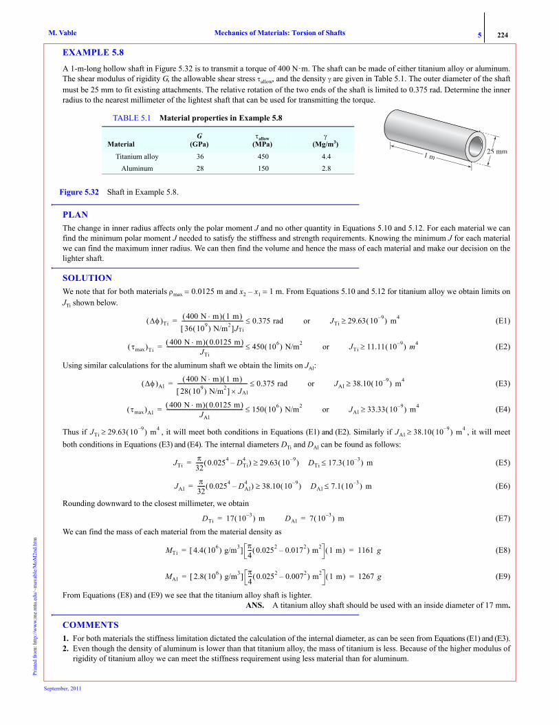
A 1-m-long hollow shaft in Figure 5.32 is to transmit a torque of 400 N·m. The shaft can be made of either titanium alloy or aluminum.The shear modulus of rigidity G, the allowable shear stress τallow, and the density γ are given in Table 5.1. The outer diameter of the shaftmust be 25 mm to fit existing attachments. The relative rotation of the two ends of the shaft is limited to 0.375 rad. Determine the innerradius to the nearest millimeter of the lightest shaft that can be used for transmitting the torque.
PLANThe change in inner radius affects only the polar moment J and no other quantity in Equations 5.10 and 5.12. For each material we canfind the minimum polar moment J needed to satisfy the stiffness and strength requirements. Knowing the minimum J for each materialwe can find the maximum inner radius. We can then find the volume and hence the mass of each material and make our decision on thelighter shaft.
SOLUTIONWe note that for both materials ρmax = 0.0125 m and x2 – x1 = 1 m. From Equations 5.10 and 5.12 for titanium alloy we obtain limits onJTi shown below.
(E1)
(E2)
Using similar calculations for the aluminum shaft we obtain the limits on JAl:
(E3)
(E4)
Thus if , it will meet both conditions in Equations (E1) and (E2). Similarly if , it will meetboth conditions in Equations (E3) and (E4). The internal diameters DTi and DAl can be found as follows:
(E5)
(E6)
Rounding downward to the closest millimeter, we obtain
(E7)We can find the mass of each material from the material density as
(E8)
(E9)
From Equations (E8) and (E9) we see that the titanium alloy shaft is lighter. ANS. A titanium alloy shaft should be used with an inside diameter of 17 mm.
COMMENTS1. For both materials the stiffness limitation dictated the calculation of the internal diameter, as can be seen from Equations (E1) and (E3).2. Even though the density of aluminum is lower than that titanium alloy, the mass of titanium is less. Because of the higher modulus of
rigidity of titanium alloy we can meet the stiffness requirement using less material than for aluminum.
1 m25 mm
Figure 5.32 Shaft in Example 5.8.
TABLE 5.1 Material properties in Example 5.8
MaterialG
(GPa)τallow
(MPa)γ
(Mg/m3)
Titanium alloy 36 450 4.4Aluminum 28 150 2.8
Δφ( )Ti400 N m⋅( ) 1 m( )
36 109( ) N/m2[ ]JTi---------------------------------------------- 0.375 rad≤= or JTi 29.63 10 9–( ) m4≥
τmax( )Ti400 N m⋅( ) 0.0125 m( )
JTi--------------------------------------------------------- 450 106( ) N/m2≤= or JTi 11.11 10 9–( ) m4≥
Δφ( )Al400 N m⋅( ) 1 m( )
28 109( ) N/m2[ ] J× Al---------------------------------------------------- 0.375 rad≤= or JAl 38.10 10 9–( ) m4≥
τmax( )Al400 N m⋅( ) 0.0125 m( )
JAl--------------------------------------------------------- 150 106( ) N/m2≤= or JAl 33.33 10 9–( ) m4≥
JTi 29.63 10 9–( ) m4≥ JAl 38.10 10 9–( ) m4≥
JTiπ32------ 0.0254 DTi
4–( ) 29.63 10 9–( ) DTi 17.3 10 3–( ) m≤≥=
JAlπ32------ 0.0254 DAl
4–( ) 38.10 10 9–( ) DAl 7.1 10 3–( ) m≤≥=
DTi 17 10 3–( ) m= DAl 7 10 3–( ) m=
MTi 4.4 106( ) g/m3[ ] π4--- 0.0252 0.0172–( ) m2 1 m( ) 1161 g= =
MAl 2.8 106( ) g/m3[ ] π4--- 0.0252 0.0072–( ) m2 1 m( ) 1267 g= =
S
eptember, 2011
5 225Mechanics of Materials: Torsion of ShaftsM. VablePr
inte
d fr
om: h
ttp://
ww
w.m
e.m
tu.e
du/~
mav
able
/MoM
2nd.
htm
3. If in Equation (E5) we had 17.95(10–3) m on the right side, our answer for DTi would still be 17 mm because we have to round down-ward to ensure meeting the less-than sign requirement in Equation (E5).
EXAMPLE 5.9
The radius of a tapered circular shaft varies from 4r units to r units over a length of 40r units, as shown in Figure 5.33. The radius of theuniform shaft shown is r units. Determine (a) the angle of twist of wheel C with respect to the fixed end in terms of T, r, and G; (b) themaximum shear stress in the shaft.
PLAN(a) We can find the relative rotation of wheel C with respect to wheel B using Equation (5.12). For section AB we obtain the polarmoment J as a function of x and integrate Equation (5.9) to obtain the relative rotation of B with respect to A. We add the two relativerotations and obtain the relative rotation of C with respect to A. (b) As per Equation (5.10), the maximum shear stress will exist where theshaft radius is minimum (J is minimum) and T is maximum. Thus by inspection, the maximum shear stress will exist on a section just leftof B.
SOLUTIONWe note that R is a linear function of x and can be written as . Noting that at x = 0 the radius we obtain .Noting that the radius we obtain . The radius R can be written as
(E1)Figure 5.34 shows the free body diagrams after imaginary cuts have been made and internal torques drawn as per our sign convention.By equilibrium of moment about the shaft axis we obtain the internal torques:
(E2)
(E3)
The polar moment of inertias can be written as
(E4)
(a) We can find the relative rotation of the section at C with respect to the section at B using Equation (5.12):
(E5)
Substituting Equations (E3) and (E4) into Equation (5.9) and integrating from point A to point B, we can find the relative rotation at thesection at B with respect to the section at A:
or
(E6)
Adding Equations (E5) and (E6), we obtain
(E7)
Figure 5.33 Shaft geometry in Example 5.9
2.5 T T
40 rA
B Cx
10 r
R x( ) a bx+= R 4r= a 4r=x 40r= R r= b 3– r 40r( )⁄ 0.075–= =
R x( ) 4r 0.075x–=
TBC T=
TAB 2.5T T–+ 0= or TAB 1.5T–=
C
TTBCT
Figure 5.34 Free-body diagrams in Example 5.9 after imaginary cut in segment (a) BC (b) AB
2.5T
B
TAB
C
T(a) (b)
JBCπ2---r4= JAB
π2---R4 π
2--- 4r 0.075x–( )4= =
φC φB–TBC xC xB–( )
GBCJBC------------------------------- T 10r( )
G π 2⁄( )r4------------------------- 6.366T
Gr3-----------------= = =
xddφ
⎝ ⎠⎛ ⎞
AB
TAB
GABJAB------------------ 1.5T–
G π 2⁄( ) 4r 0.075x–( )4--------------------------------------------------------= = or dφ
φA
φB
∫ 3TGπ 4r 0.075x–( )4-------------------------------------------- – dx
xA
xB
∫=
φB φA– 3TGπ--------– 1
3–------ 1
0.075–---------------- 1
4r 0.075x–( )3-----------------------------------
0
40r T0.075Gπ----------------------– 1
r3---- 1
4r( )3-------------– 4.178 T
Gr3---------–= = =
φC φA– TGr3--------- 6.366 4.178–( )=
September, 2011

5 226Mechanics of Materials: Torsion of ShaftsM. VablePr
inte
d fr
om: h
ttp://
ww
w.m
e.m
tu.e
du/~
mav
able
/MoM
2nd.
htm
ANS.
(b) Just left of the section at B we have JAB = πr4/2 and ρmax = r. Substituting these values into Equation (5.10), we obtain the maximumtorsional shear stress in the shaft as
(E8)
ANS.
Dimension check: The dimensional consistency3 of the answer is checked as follows:
COMMENT1. The direction of the shear stress can be determined using subscripts or intuitively, as shown in Figure 5.35.
EXAMPLE 5.10
A uniformly distributed torque of q in.·lb/in. is applied to an entire shaft, as shown in Figure 5.36. In addition to the distributed torque a con-centrated torque of T = 3qL in.·lb is applied at section B. Let the shear modulus be G and the radius of the shaft r. In terms of q, L, G, and r,determine: (a) The rotation of the section at C. (b) The maximum shear stress in the shaft.
PLAN(a) The internal torque in segments AB and BC as a function of x must be determined first. Then the relative rotation in each section isfound by integrating Equation (5.9). (b) Since J and ρmax are constant over the entire shaft, the maximum shear stress will exist on a sec-tion where the internal torque is maximum. By plotting the internal torque as a function of x we can determine its maximum value.
Figure 5.37 shows the free body diagrams after imaginary cuts are made at x distance from A and internal torques drawn as per our signconvention. We replace the distributed torque by an equivalent torque that is equal to the distributed torque intensity multiplied by thelength of the cut shaft (the rectangular area). From equilibrium of moment about the shaft axis in Figure 5.37 we obtain the internaltorques:
(E1)
(E2)
3O( ) represents the dimension of the quantity on the left. F represents dimension for the force. L represents the dimension for length. Thusshear modulus, which has dimension of force (F) per unit area (L2), is represented as O(F/L2).
φC φA– 2.2 TGr3--------- ccw=
τmax1.5T– r
πr4 2⁄----------------- 0.955T
r3-----------------–= =
τmax 0.955 T r3⁄( )=
T O FL( ) r O L( ) G O FL2-----⎝ ⎠
⎛ ⎞→→→ φ O ( ) TGr3--------- O
FLFL2-----L3------------
⎝ ⎠⎜ ⎟⎜ ⎟⎛ ⎞
O ( ) checks→ → → →
τ O FL2-----⎝ ⎠
⎛ ⎞ Tr3---- O FL
L3-------⎝ ⎠
⎛ ⎞ O FL2-----⎝ ⎠
⎛ ⎞ checks→ →→→
B
Shear stress opposingcounterclockwisemotion of left segment
x��
Negative �x�
(a) (b)
Figure 5.35 Direction of shear stress in Example 5.9: (a) by subscripts; (b) by inspection.
T � 3qL inL �lb q in�lbin
C
L 2L Figure 5.36 Shaft and loading in Example 5.10.
TAB 3qL q 3L x–( )–+ 0= or TAB q– x=
TBC q 3L x–( )– 0= or TBC q 3L x–( )=
September, 2011

5 227Mechanics of Materials: Torsion of ShaftsM. VablePr
inte
d fr
om: h
ttp://
ww
w.m
e.m
tu.e
du/~
mav
able
/MoM
2nd.
htm
Integrating Equation (5.9) for each segment we obtain the relative rotations of segment ends as
(E3)
or
(E4)
(a) Adding Equations (E3) and (E4), we obtain the rotation of the section at C with respect to the section at A:
(E5)
ANS.
(b) Figure 5.38 shows the plot of the internal torque as a function of x using Equations (E1) and (E2). The maximum torque will occur ona section just to the right of B. From Equation (5.10) the maximum torsional shear stress is
(E6)
ANS.
Dimension check: The dimensional consistency (see footnote 12) of our answers is checked as follows:
COMMENT1. A common mistake is to write the incorrect length of the shaft as a function of x in the free-body diagrams. It should be remembered
that the location of the cut is defined by the variable x, which is measured from the common origin for all segments. Each cut pro-duces two parts, and we are free to choose either part.
T � 3qL inL �lb
TABT
3L � x
q in� inT � 3qL inL �lb q(3L x)
C
TABT3L � x
C
Figure 5.37 Free-body diagrams in Example 5.10 after imaginary cut in segment (a) AB, and (b) BC.
TBCT
3L � x
q in�lbinq(3L � x)
C
TBCT3L � x
C
(a)
(b)
xddφ
⎝ ⎠⎛ ⎞
AB
TAB
GABJAB------------------= q– x
Gπr4 2⁄--------------------= or dφ
φA
φB
∫2qx
Gπr4------------- dx
xA=0
xB= L
∫–= or φB φA– qx2
Gπr4------------–
0
L qL2
Gπr4------------–= =
xddφ
⎝ ⎠⎛ ⎞
BC
TBC
GBCJBC-----------------= q 3L x–( )
Gπr4 2⁄----------------------- = or dφ
φB
φC
∫2q 3L x–( )
Gπr4-------------------------- dx
xB=L
xC=3L
∫=
φC φB– 2qGπr4------------- 3Lx x2
2----–⎝ ⎠
⎛ ⎞L
3L2q
Gπr4------------- 9L2 3L( )2
2-------------– 3L2– L2
2-----+ 4qL2
Gπr4-------------= = =
φC φA– qL2
Gπr4------------– 4qL2
Gπr4-------------+=
φC φA– 3qL2
Gπr4-------------
⎝ ⎠⎜ ⎟⎛ ⎞
= ccw=
τmaxTmaxρmax
J---------------------- 2qL( ) r( )
πr4 2⁄----------------------= =
τmax 4qLπr3----------=
T
2qL
A BL 3L
C
qL
x Figure 5.38 Torque diagram in Example 5.10.
q O FLL
-------⎝ ⎠⎛ ⎞ O F( ) r O L( ) L O L( ) G O F
L2-----⎝ ⎠
⎛ ⎞→→→→→
φ O ( )→ qL2
Gr4--------- O FL2
F L2⁄( )L4------------------------⎝ ⎠
⎛ ⎞ O ( ) checks→ →→ τ O FL2-----⎝ ⎠
⎛ ⎞→ qLr3------ O FL
L3-------⎝ ⎠
⎛ ⎞ O FL2-----⎝ ⎠
⎛ ⎞ checks→ →→
September, 2011

5 228Mechanics of Materials: Torsion of ShaftsM. VablePr
inte
d fr
om: h
ttp://
ww
w.m
e.m
tu.e
du/~
mav
able
/MoM
2nd.
htm
5.2.7* General Approach to Distributed Torque
Distributed torques are usually due to inertial forces or frictional forces acting on the surface of the shaft. The internal torque Tbecomes a function of x when a shaft is subjected to a distributed external torque, as seen in Example 5.10. If t(x) is a simplefunction, then we can find T as a function of x by drawing a free-body diagram, as we did in Example 5.10. However, if the dis-tributed torque t(x) is a complex function (see Problems 5.39, 5.61, and 5.62), it may be easier to use the alternative solutionmethod described in this section.
Consider an infinitesimal shaft element that is created by making two imaginary cuts at a distance dx from each other, asshown in Figure 5.39a.
By equilibrium moments about the axis of the shaft, we obtain or
(5.14)
Equation (5.14) represents the equilibrium equation at any section x. It assumes that t(x) is positive counterclockwise with respectto the x axis. The sign of T obtained from Equation (5.14) corresponds to the direction defined by the sign convention. If t (x) iszero in a segment of a shaft, then the internal torque is constant in that segment.
Equation (5.14) can be integrated to obtain the internal torque T. The integration constant can be found by knowing the valueof the internal torque T at either end of the shaft. To obtain the value of T at the end of the shaft (say, point A), a free-body dia-gram is constructed after making an imaginary cut at an infinitesimal distance ε from the end, as shown in Figure 5.39b.We thenwrite the equilibrium equation as
(5.15)
Equation (5.15) shows that the distributed torque does not affect the boundary condition on the internal torque. The value of theinternal torque T at the end of the shaft is equal to the concentrated external torque applied at the end. Equation (5.14) is a differ-ential equation. Equation (5.15) is a boundary condition. A differential equation and all the conditions necessary to solve it iscalled the boundary value problem.
EXAMPLE 5.11
The external torque on a drill bit varies linearly to a maximum intensity of q in.·lb/in., as shown in Figure 5.40. If the drill bit diameter isd, its length L, and the modulus of rigidity G, determine the relative rotation of the end of the drill bit with respect to the chuck.
PLAN The relative rotation of section B with respect to section A has to be found. We can substitute the given distributed torque in Equation(5.14) and integrate to find the internal torque as a function of x. We can find the integration constant by using the condition that at sec-tion B the internal torque will be zero. We can substitute the internal torque expression into Equation (5.9) and integrate from point A topoint B to find the relative rotation of section B with respect to section A.
dx
T T � dT
t(x) dx
Figure 5.39 (a) Equilibrium of an infinitesimal shaft element. (b) Boundary condition on internal torque.
TextTTTAT
t(xAx )
�
(a) (b)
T dT+( ) t x( ) dx T–+ 0=
xddT t x( )+ 0=
Text TA– t xA( )ε–[ ]ε 0→lim 0 or TA Text==
Figure 5.40 Distributed torque on a drill bit in Example 5.11.
L
q xL---⎝ ⎠
⎛ ⎞ in. lb/in.⋅
x
AB
September, 2011

5 229Mechanics of Materials: Torsion of ShaftsM. VablePr
inte
d fr
om: h
ttp://
ww
w.m
e.m
tu.e
du/~
mav
able
/MoM
2nd.
htm
SOLUTIONThe distributed torque on the drill bit is counterclockwise with respect to the x axis. Thus we can substitute t(x) = q(x/L) into Equation(5.14) to obtain the differential equation shown as Equation (E1). At point B, that is, at x = L, the internal torque should be zero as thereis no concentrated applied torque at B.The boundary condition is shown as Equation (E2). The boundary value problem statement is
• Differential Equation
(E1)
• Boundary Condition
(E2)Integrating Equation (E1) we obtain
(E3)
Substituting Equation (E2) into Equation (E3) we obtain the integration constant c as
(E4)
Substituting Equation (E4) into Equation (E3) we obtain internal torque as
(E5)
Substituting Equation (E5) into Equation (5.9) and integrating we obtain the relative rotation of the section at B with respect to the sectionat A as
(E6)
ANS.
Dimension check: The dimensional consistency (see footnote 12) of our answer is checked as follows:
COMMENTS1. No free-body diagram was needed to find the internal torque because Equation (5.14) is an equilibrium equation. It is therefore valid
at each and every section of the shaft.2. We could have obtained the internal torque by integrating Equation (5.14) from L to x as follows:
3. The internal torque can also be found using a free-body diagram. We can make an imaginary cut at some location x and draw the free-body diagram of the right side. The distributed torque represented by is the area of the trapezoid BCDE, and this observationcan be used in drawing a statically equivalent diagram, as shown in Figure 5.41. Equilibrium then gives us the value of the internaltorque as before. We can find the internal torque as shown.
4. The free-body diagram approach in Figure 5.41 is intuitive but more tedious and difficult than the use of Equation (5.14). As the func-tion representing the distributed torque grows in complexity, the attractiveness of the mathematical approach of Equation (5.14)grows correspondingly.
xddT q x
L---+ 0=
T x L=( ) 0=
T q– x2
2L------ c+=
q– L2
2L------ c+ 0 or c qL
2------==
T q2L------ L2 x2–( )=
xddφ q 2L⁄( ) L2 x2–( )
Gπd4 32⁄----------------------------------------= or dφ
φA
φB
∫16q
πGLd4----------------- L2 x2–( ) dx
xA= 0
xB=L
∫= or φB φA– 16qπGLd4----------------- L2x x3
3----–⎝ ⎠
⎛ ⎞
0
L
=
φB φA– 32qL2
3πGd4----------------- ccw=
q O FLL
-------⎝ ⎠⎛ ⎞ O F( )→→ d O L( )→ L O L( )→ G O F
L2-----⎝ ⎠
⎛ ⎞→ φ O ( )→ qL2
Gd 4---------- O FL2
F L2⁄( )L4------------------------⎝ ⎠
⎛ ⎞ O ( ) checks→ →→
TdTB= 0
T
∫ t x( ) xdxB=L
x
∫– q xL---⎝ ⎠
⎛ ⎞ xdL
x
∫– q2L------ L2 x2–( )= = =
t x( ) xdx
L∫
qxL------
B
C
D
E
q
12--- qx
L------ q+⎝ ⎠
⎛ ⎞ L x–( ) q2L------ L2 x2–( )=
TT
Figure 5.41 Internal torque by free-body diagram in Example 5.11.
September, 2011

5 230Mechanics of Materials: Torsion of ShaftsM. VablePr
inte
d fr
om: h
ttp://
ww
w.m
e.m
tu.e
du/~
mav
able
/MoM
2nd.
htm
MoM in Action: Drill, the Incredible Tool
Drills have been in use for almost as long as humans have used tools. Early humans knew from experience that friction
generated by torquing a wooden shaft could start a fire—a technique still taught in survivalist camps. Archeologists in
Pakistan have found teeth perhaps 9000 years old showing the concentric marks of a flint stone drill. The Chinese used
larger drills in the 3rd B.C.E. to extract water and oil from earth. The basic design—a chuck that delivers torque to the drill
bit—has not changed, but their myriad uses to make holes from the very small to the very large continues to grow.
Early development of the drill was driven by the technology of delivering power to the drill bit. In 1728, French dentist
Pierre Fauchard (Figure 5.42a) described how catgut twisted around a cylinder could power the rotary movement as a bow
moved back and forth. However, hand drills like these operated at only about 15 rpm. George F. Harrington introduced the
first motor-driven drill in 1864, powered by the spring action of a clock. George Green, an American dentist, introduced a
pedal-operated pneumatic drill just four years later—and, in 1875, an electric drill. By 1914 dental drills could operate at
3000 rpm.
Other improvements took better understanding of the relationship between power, torsion, and shear stress in the drill bit
(problems 5.45—5.47) and the material being drilled:
• The sharper the drill tip, the higher the shear stresses at the point, and the greater the amount of material that can be
sheared. For most household jobs the angle of the drill tip is 118o. For soft materials such as plastic, the angle is sharper, while for harder material such as steel the angle is shallower.
• For harder materials low speeds can prolong the life of drill bit. However, in dentistry higher speeds, of up to 500,000 rpm, reduce a patient’s pain.
• Slower speeds are also used to shear a large amount of material. Tunnel boring machines (TBM) shown in Figure 5.42b may operate at 1 to 10 rpm. The world’s largest TBM, with a diameter of 14.2 m, was used to drill the Elbe Tunnel in Hamburg, Germany. Eleven TBM’s drilled the three pipes of the English Channel, removing 10.5 million cubic yards of earth in seven years.
• Drill bits can be made of steel, tungsten carbide, polycrystalline diamonds, titanium nitrate, and diamond powder. The choice is dictated by the material to be drilled as well as the cost. Even household drills have different bits for wood, metal, or masonry. Delivery and control of power to the drill bit are engineering challenges. So is removal of sheared material, not only to
prevent the hole from plugging, but also because the material carries away heat, improving the strength and life of a drill bit.
Yet the fundamental function of a drill remains: shearing through torsion.
Figure 5.42 (a) Pierre Fauchard drill. (b) Tunnel boring machine Matilda (Courtesy Erikt9).
(a) (b)
September, 2011

5 231Mechanics of Materials: Torsion of ShaftsM. VablePr
inte
d fr
om: h
ttp://
ww
w.m
e.m
tu.e
du/~
mav
able
/MoM
2nd.
htm
PROBLEM SET 5.2
5.19 The torsional shear stress at point A on a solid circular homogenous cross-section was found to be τA= 120 MPa. Determine themaximum torsional shear stress on the cross-section.
5.20 The torsional shear strain at point A on a homogenous circular section shown in Figure P5.20 was found to be 900 μ rads. Using ashear modulus of elasticity of 4000 ksi, determine the torsional shear stress at point B.
5.21 An aluminum shaft (Gal= 28 GPa) and a steel shaft (GS=82 GPa) are securely fastened to form composite shaft with a cross sectionshown in Figure P5.21. If the maximum torsional shear strain in aluminum is 1500 μ rads, determine the maximum torsional shear strain in steel.
5.22 An aluminum shaft (Gal= 28 GPa) and a steel shaft (GS=82 GPa) are securely fastened to form composite shaft with a cross sectionshown in Figure P5.21. If the maximum torsional shear stress in aluminum is 21 MPa, determine the maximum torsional shear stress in steel.
5.23 Determine the direction of torsional shear stress at points A and B in Figure P5.23 (a) by inspection; (b) by using the sign conventionfor internal torque and the subscripts. Report your answer as a positive or negative τxy.
60 mm
100 mm
A
300
Figure P5.19
1.5 in.
2.5 in.
A
300 550
B
Figure P5.20
60 mm
100 mm
Steel
Figure P5.21
Aluminum
y
T
x
A
x
B
Figure P5.23
September, 2011

5 232Mechanics of Materials: Torsion of ShaftsM. VablePr
inte
d fr
om: h
ttp://
ww
w.m
e.m
tu.e
du/~
mav
able
/MoM
2nd.
htm
5.24 Determine the direction of torsional shear stress at points A and B in Figure P5.24 (a) by inspection; (b) by using the sign conventionfor internal torque and the subscripts. Report your answer as a positive or negative τxy
5.25 Determine the direction of torsional shear stress at points A and B in Figure P5.25 (a) by inspection; (b) by using the sign conventionfor internal torque and the subscripts. Report your answer as a positive or negative τxy.
5.26 Determine the direction of torsional shear stress at points A and B in Figure P5.26 (a) by inspection; (b) by using the sign conventionfor internal torque and the subscripts. Report your answer as a positive or negative τxy.
5.27 The two shafts shown in Figure P5.27 have the same cross sectional areas A. Show that the ratio of the polar moment of inertia of thehollow shaft to that of the solid shaft is given by the equation below.:
5.28 Show that for a thin tube of thickness t and center-line radius R the polar moment of inertia can be approximated by Bythin tube we imply
5.29 (a) Draw the torque diagram in Figure P5.29. (b) Check the values of internal torque by making imaginary cuts and drawing free-body diagrams. (c) Determine the rotation of the rigid wheel D with respect to the rigid wheel A if the torsional rigidity of the shaft is 90,000kips·in.2.
x
xy
T
B
A
Figure P5.24
T
y
xB
xA
Figure P5.25
T
x
x
y
A
B Figure P5.26
RH
�RH
RS
Figure P5.27
Jhollow
Jsolid-------------- α2 1+
α2 1–---------------=
J 2πR3t .=t R 10⁄ .<
September, 2011
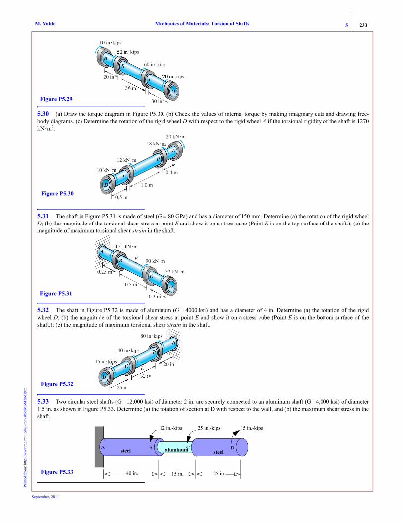
5 233Mechanics of Materials: Torsion of ShaftsM. VablePr
inte
d fr
om: h
ttp://
ww
w.m
e.m
tu.e
du/~
mav
able
/MoM
2nd.
htm
5.30 (a) Draw the torque diagram in Figure P5.30. (b) Check the values of internal torque by making imaginary cuts and drawing free-body diagrams. (c) Determine the rotation of the rigid wheel D with respect to the rigid wheel A if the torsional rigidity of the shaft is 1270kN·m2.
5.31 The shaft in Figure P5.31 is made of steel (G = 80 GPa) and has a diameter of 150 mm. Determine (a) the rotation of the rigid wheelD; (b) the magnitude of the torsional shear stress at point E and show it on a stress cube (Point E is on the top surface of the shaft.); (c) themagnitude of maximum torsional shear strain in the shaft.
5.32 The shaft in Figure P5.32 is made of aluminum (G = 4000 ksi) and has a diameter of 4 in. Determine (a) the rotation of the rigidwheel D; (b) the magnitude of the torsional shear stress at point E and show it on a stress cube (Point E is on the bottom surface of theshaft.); (c) the magnitude of maximum torsional shear strain in the shaft.
5.33 Two circular steel shafts (G =12,000 ksi) of diameter 2 in. are securely connected to an aluminum shaft (G =4,000 ksi) of diameter1.5 in. as shown in Figure P5.33. Determine (a) the rotation of section at D with respect to the wall, and (b) the maximum shear stress in theshaft.
60 in�kips
�kips
36
30 in
10 in�kips
�kips
Figure P5.29
10 kN
12 kN�m
0.5 m
1.0 m
18 kN20 kN�m
Figure P5.30
90 kN�m
N�m
0.25 m
0.5 m
0.3 m
70 kN�m
E
Figure P5.31
25 in
n
20 in
80 in�
40 in�kips
15 in�kips
Figure P5.32
40 in. 15 in. 25 in.
Bsteel
12 in.-kips 25 in.-kips 15 in.-kips
Figure P5.33
steelaluminum DCA
September, 2011

5 234Mechanics of Materials: Torsion of ShaftsM. VablePr
inte
d fr
om: h
ttp://
ww
w.m
e.m
tu.e
du/~
mav
able
/MoM
2nd.
htm
5.34 A solid circular steel shaft BC (Gs = 12,000 ksi) is securely attached to two hollow steel shafts AB and CD, as shown in FigureP5.34. Determine (a) the angle of rotation of the section at D with respect to the section at A; (b) the magnitude of maximum torsionalshear stress in the shaft; (c) the torsional shear stress at point E and show it on a stress cube. (Point E is on the inside bottom surface of CD.)
5.35 A steel shaft (G = 80 GPa) is subjected to the torques shown in Figure P5.35. Determine (a) the rotation of section A with respect tothe no-load position; (b) the torsional shear stress at point E and show it on a stress cube. (Point E is on the surface of the shaft.)
Tapered shafts5.36 The radius of the tapered circular shaft shown in Figure P5.36 varies from 200 mm at A to 50 mm at B. The shaft between B and Chas a constant radius of 50 mm. The shear modulus of the material is G = 40 GPa. Determine (a) the angle of rotation of wheel C withrespect to the fixed end; (b) the maximum shear strain in the shaft
5.37 The radius of the tapered shaft in Figure P5.37 varies as . Determine the rotation of the section at B in terms of theapplied torque Text, length L, shear modulus of elasticity G, and geometric parameters K and a.
5.38 The radius of the tapered shaft shown in Figure P5.37 varies as . In terms of Text, L, G, and r, determine (a) therotation of the section at B; (b) the magnitude of maximum torsional shear stress in the shaft.
Distributed torques5.39 The external torque on a drill bit varies as a quadratic function to a maximum intensity of q in.·lb/in., as shown in Figure P5.39. Ifthe drill bit diameter is d, its length L, and its modulus of rigidity G, determine (a) the maximum torsional shear stress on the drill bit; (b) therelative rotation of the end of the drill bit with respect to the chuck.
24 in 24 in
2 in
100 in�kips200 in�kips420 in�kips120 in�kips
36 in Figure P5.34
2.0 m
A
2.5 m
160 kN�m
120 kN�m80 kN�m
Figure P5.35
7.5 mA B Cx
2 m
10 kN m⋅ 2.5 kN m⋅
Figure P5.36
R Ke ax–=
�m
x
Text
Figure P5.37
R r 2 0.25x L⁄–( )=
L
q x2
L2------
⎝ ⎠⎜ ⎟⎛ ⎞
in. lb/in.⋅
x
Figure P5.39
September, 2011

5 235Mechanics of Materials: Torsion of ShaftsM. VablePr
inte
d fr
om: h
ttp://
ww
w.m
e.m
tu.e
du/~
mav
able
/MoM
2nd.
htm
5.40 A circular solid shaft is acted upon by torques, as shown in Figure P5.40. Determine the rotation of the rigid wheel A with respect tothe fixed end C in terms of q, L, G, and J.
Design problems
5.41 A thin steel tube (G = 12,000 ksi) of -in. thickness has a mean diameter of 6 in. and a length of 36 in. What is the maximum torquethe tube can transmit if the allowable torsional shear stress is 10 ksi and the allowable relative rotation of the two ends is 0.015 rad?
5.42 Determine the maximum torque that can be applied on a 2-in. diameter solid aluminum shaft (G = 4000 ksi) if the allowable tor-sional shear stress is 18 ksi and the relative rotation over 4 ft of the shaft is to be limited to 0.2 rad.
5.43 A hollow steel shaft (G = 80 GPa) with an outside radius of 30 mm is to transmit a torque of 2700 N·m. The allowable torsionalshear stress is 120 MPa and the allowable relative rotation over 1 m is 0.1 rad. Determine the maximum permissible inner radius to the near-est millimeter.
5.44 A 5-ft-long hollow shaft is to transmit a torque of 200 in.·kips. The outer diameter of the shaft must be 6 in. to fit existing attach-ments. The relative rotation of the two ends of the shaft is limited to 0.05 rad. The shaft can be made of steel or aluminum. The shear mod-ulus of elasticity G, the allowable shear stress τallow, and the specific weight γ are given in Table P5.44. Determine the maximum innerdiameter to the nearest in. of the lightest shaft that can be used for transmitting the torque and the corresponding weight.
Transmission of power
Power P is the rate at which work is done; and work W done by a constant torque is equal to the product of torque T and angle of rota-tion φ. Noting that , we obtain
(5.16)where T is the torque transmitted, ω is the rotational speed in radians per second, and f is the frequency of rotation in hertz (Hz). Power is reportedin units of horsepower in U.S. customary units or in watts. 1 horsepower (hp) is equal to 550 ft·lb/s = 6600 in·lb/s and 1 watt (W) is equal to 1N·m/s. Use Equation (5.16) to solve Problems 5.38 through 5.40.
5.45 A 100-hp motor is driving a pulley and belt system, as shown in Figure P5.45. If the system is to operate at 3600 rpm, determine theminimum diameter of the solid shaft AB to the nearest in. if the allowable stress in the shaft is 10 ksi.
5.46 The bolts used in the coupling for transferring power in Problem 5.45 have an allowable strength of 12 ksi. Determine the minimumnumber (> 4) of -in. diameter bolts that must be placed at a radius of in.
5.47 A 20-kW motor drives three gears, which are rotating at a frequency of 20 Hz. Gear A next to the motor transfers 8 kW of power.Gear B, which is in the middle, transfers 7 kW of power. Gear C, which is at the far end from the motor, transfers the remaining 5 kW ofpower. A single solid steel shaft connecting the motors to all three gears is to be used. The steel used has a yield strength in shear of 145
TABLE P5.44
MaterialG
(ksi)τallow(ksi)
γ(lb/in.3)
Steel 12,000 18 0.285Aluminum 4,000 10 0.100
AAAA B
0.5 L 0.5 L
q in�TBT in�TAT 2qL in�lb
Figure P5.40
18---
18---
dW dt⁄ω dφ dt⁄=
P Tω 2πf T= =
18---
Figure P5.45
14--- 5
8---
September, 2011

5 236Mechanics of Materials: Torsion of ShaftsM. VablePr
inte
d fr
om: h
ttp://
ww
w.m
e.m
tu.e
du/~
mav
able
/MoM
2nd.
htm
MPa. Assuming a factor of safety of 1.5, what is the minimum diameter of the shaft to the nearest millimeter that can be used if failure dueto yielding is to be avoided? What is the magnitude of maximum torsional stress in the segment between gears A and B?
Stretch yourself
5.48 A circular shaft has a constant torsional rigidity GJ and is acted upon by a distributed torque t(x). If at section A the internal torque iszero, show that the relative rotation of the section at B with respect to the rotation of the section at A is given by
(5.17)
5.49 A composite shaft made from n materials is shown in Figure P5.49. Gi and Ji are the shear modulus of elasticity and polar momentof inertia of the ith material. (a) If Assumptions from 1 through 6 are valid, show that the stress in the ith material is given Equation(5.18a), where T is the total internal torque at a cross section. (b) If Assumptions 8 through 10 are valid, show that relative rotation is given by Equation (5.18b). (c) Show that for G1=G2=G3....=Gn=G Equations (5.18a) and (5.18b) give the same results as Equations (5.10)and (5.12).
5.50 A circular solid shaft of radius R is made from a nonlinear material that has a shear stress-shear strain relationship given by τ = Gγ0.5.Assume that the kinematic assumptions are valid and shear strain varies linearly with the radial distance across the cross-section. Determinethe maximum shear stress and the rotation of section at B in terms of external torque Text, radius R, material constant G, and length L.
5.51 A hollow circular shaft is made from a non-linear materials that has the following shear stress--shear strain relation τ = Gγ2. Assumethat the kinematic assumptions are valid and shear strain varies linearly with the radial distance across the cross-section. In terms of internaltorque T, material constant G, and R, obtain formulas for (a) the maximum shear stress and (b) the relative rotation of twocross-sections at x1 and x2.
5.52 A solid circular shaft of radius R and length L is twisted by an applied torque T. The stress–strain relationship for a nonlinear mate-rial is given by the power law . If Assumptions 1 through 4 are applicable, show that the maximum shear stress in the shaft and therelative rotation of the two ends are as follows:
Substitute n = 1 in the formulas and show that we obtain the same results as from Equations 5.10 and 5.12.
φB φA– 1GJ------- x xB–( )t x( ) dx
xA
xB
∫=
τxθ( )iφ2 φ1–
Figure P5.49
(5.18a)
(5.18b)
τxθ( )iGiρT
GjJjj=1
n
∑-----------------------=
φ2 φ1–T x2 x1–( )
GjJjj=1
n
∑------------------------=
Text
L
B
Figure P5.50
A
τmax φ2 φ1–
R
2R Figure P5.51
τ Gγ n=
τmaxT n 3+( )
2πR3---------------------= Δφ n 3+( )T
2πGR3+n----------------------
1 n⁄L=
S
eptember, 2011
5 237Mechanics of Materials: Torsion of ShaftsM. VablePr
inte
d fr
om: h
ttp://
ww
w.m
e.m
tu.e
du/~
mav
able
/MoM
2nd.
htm
5.53 The internal torque T and the displacements of a point on a cross section of a noncircular shaft shown in Figure P5.53 are given bythe equations below
where u, v, and w are the displacements in the x, y, and z directions, respectively; is the rate of twist and is considered constant. is called the warping function4 and describes the movement of points out of the plane of cross section. Using Equations (2.12d) and
(2.12f) and Hooke’s law, show that the shear stresses for a noncircular shaft are given by
(5.21)
5.54 Show that for circular shafts, the equations in Problem 5.53 reduce to Equation (5.9).
5.55 Consider the dynamic equilibrium of the differential element shown in Figure P5.55, where T is the internal torque, γ is the materialdensity, J is the polar area moment of inertia, and is the angular acceleration. Show that dynamic equilibrium results in Equation(5.22)
5.56 Show by substitution that the solution of Equation (5.23) satisfies Equation (5.22):
(5.23)
where A, B, C, and D are constants that are determined from the boundary conditions and the initial conditions and ω is the frequency ofvibration.
Computer problems
5.57 A hollow aluminum shaft of 5 ft in length is to carry a torque of 200 in.·kips. The inner radius of the shaft is 1 in. If the maximumtorsional shear stress in the shaft is to be limited to 10 ksi, determine the minimum outer radius to the nearest in.
5.58 A 4-ft-long hollow shaft is to transmit a torque of 100 in.·kips. The relative rotation of the two ends of the shaft is limited to0.06 rad. The shaft can be made of steel or aluminum. The shear modulus of rigidity G, the allowable shear stress τallow, and the specificweight γ are given in Table P5.58. The inner radius of the shaft is 1 in. Determine the outer radius of the lightest shaft that can be used for trans-mitting the torque and the corresponding weight.
5.59 Table P5.59 shows the measured radii of the solid tapered shaft shown in Figure P5.59, at several points along the axis of the shaft.The shaft is made of aluminum (G = 28 GPa) and has a length of 1.5 m. Determine: (a) the rotation of the free end with respect to the wallusing numerical integration; (b) the maximum shear stress in the shaft.
4Equations of elasticity show that the warping function satisfies the Laplace equation,
TABLE P5.58
Material G (ksi) τallow (ksi) γ (lb/in.3)
Steel 12,000 18 0.285Aluminum 4000 10 0.100
y
x
z
dVyVV �xy� dAdd
dV
T
y
x
Figure P5.53 Torsion of noncircular shafts.
(5.19a)
(5.19b)
(5.19c)
(5.20)
u ψ y z,( ) xd
dφ=
v xz xd
dφ–=
w xy xd
dφ=
T yτxz zτxy–( ) AdA
∫=
dφ dx⁄ψ x y,( )
∂2ψ ∂⁄ y2 ∂2ψ ∂⁄ z2 0.=+
τxy Gy∂
∂ψ z–⎝ ⎠⎛ ⎞
xddφ= τxz G
z∂∂ψ y+⎝ ⎠
⎛ ⎞xd
dφ=
ψ x y,( ) 0,=
∂2φ ∂⁄ t2
T � dTT
dx
�J�� dx�2
t2
dx Figure P5.55 Dynamic equilibrium.
(5.22)t2
2
∂
∂ φ c2 x2
2
∂
∂ φ where c Gγ----==
φ A ωxc
-------cos B ωxc
-------sin+⎝ ⎠⎛ ⎞ C ωtcos D ωtsin+( )×=
18---
Se
ptember, 2011
5 238Mechanics of MateM. VablePr
inte
d fr
om: h
ttp://
ww
w.m
e.m
tu.e
du/~
mav
able
/MoM
2nd.
htm
5.60 Let the radius of the tapered shaft in Problem 5.59 be represented by the equation R(x) = a + bx. Using the data in Table P5.59 deter-mine the constants a and b by the least-squares method and then find the rotation of the section at B by analytical integration.
5.61 Table P5.61 shows the values of distributed torque at several points along the axis of the solid steel shaft (G = 12,000 ksi) shown inFigure P5.61. The shaft has a length of 36 in. and a diameter of 1 in. Determine (a) the rotation of end A with respect to the wall using numer-ical integration; (b) the maximum shear stress in the shaft.
5.62 Let the distributed torque t(x) in Problem 5.61 be represented by the equation t(x) = a + bx + cx2. Using the data in Table P5.61determine the constants a, b, and c by the least-squares method and then find the rotation of the section at B by analytical integration.
QUICK TEST 5.1 Time: 20 minutes/Total: 20 points
�m
x
Figure P5.59
TABLE P5.59
x (m)
R(x) (mm)
0.0 100.60.1 92.70.2 82.60.3 79.60.4 75.90.5 68.80.6 68.00.7 65.9
0.8 60.10.9 60.31.0 59.11.1 54.01.2 54.81.3 54.11.4 49.41.5 50.6
TABLE P5.59
x (m)
R(x) (mm)
T 35 kN m⋅=
TABLE P5.61
x(in.)
t(x)(in.·lb/in.)
0 93.03 146.06 214.19 260.4
12 335.015 424.718 492.6
21 588.824 700.127 789.630 907.433 1040.336 1151.4
TABLE P5.61
x(in.)
t(x)(in.·lb/in.)
September, 2011
rials: Torsion of Shafts

5 239Mechanics of Materials: Torsion of ShaftsM. VablePr
inte
d fr
om: h
ttp://
ww
w.m
e.m
tu.e
du/~
mav
able
/MoM
2nd.
htm
5.3 STATICALLY INDETERMINATE SHAFTS
In Chapter 4 we saw the solution of statically indeterminate axial problems require equilibrium equations and compatibilityequations. This is equally true for statically indeterminate shafts. The primary focus in this section will be on the solution of stat-ically indeterminate shafts that are on a single axis. However, equilibrium equations and compatibility equations can also beused for solution of shafts with composite cross section, as will be demonstrated in Example 5.14. The use of equilibrium equa-tions and compatibility equations to shafts on multiple axis is left as exercises in Problem Set 5.3.
Figure 5.43 shows a statically indeterminate shaft. In statically indeterminate shafts we have two reaction torques, one at theleft and the other at the right end of the shaft. But we have only one static equilibrium equation, the sum of all torques in the xdirection should be zero. Thus the degree of static redundancy is 1 and we need to generate 1 compatibility equation. We shalluse the continuity of φ and the fact that the sections at the left and right walls have zero rotation. The compatibility equation statethat the relative rotation of the right wall with respect to the left wall is zero. Once more we can use either the displacementmethod or the force method:
1. In the displacement method, we can use the rotation of the sections as the unknowns. If torque is applied at severalsections along the shaft, then the rotation of each of the sections is treated as an unknown.
2. In the force method, we can use either the reaction torque as the unknown or the internal torques in the sections as theunknowns. Since the degree of static redundancy is 1, the simplest approach is often to take the left wall (or the rightwall) reaction as the unknown variable. We can then apply the compatibility equation, as outlined next.
5.3.1 General Procedure for Statically Indeterminate Shafts.
Step 1 Make an imaginary cut in each segment and draw free-body diagrams by taking the left (or right) part if the left(right) wall reaction is carried as the unknown in the problem. Alternatively, draw the torque diagram in terms of the reactiontorque.
Step 2 Write the internal torque in terms of the reaction torque.Step 3 Using Equation (5.12) write the relative rotation of each segment ends in terms of the reaction torque.
Answer true or false and justify each answer in one sentence. Grade yourself with the answers given in Appendix E.
1. Torsional shear strain varies linearly across a homogeneous cross section. 2. Torsional shear strain is a maximum at the outermost radius for a homogeneous and a nonhomogeneous cross section. 3. Torsional shear stress is a maximum at the outermost radius for a homogeneous and a nonhomogeneous cross section.4. The formula can be used to find the shear stress on a cross section of a tapered shaft. 5. The formula can be used to find the relative rotation of a segment of a tapered shaft.6. The formula can be used to find the shear stress on a cross section of a shaft subjected to distributed
torques.7. The formula can be used to find the relative rotation of a segment of a shaft subjected to dis-
tributed torques.8. The equation cannot be used for nonlinear materials.
9. The equation can be used for a nonhomogeneous cross section.
10.Internal torques jump by the value of the concentrated external torque at a section.
τxθ Tρ J⁄=φ2 φ1– T x2 x1–( ) G⁄ J=τxθ Tρ J⁄=
φ2 φ1– T x2 x1–( ) G⁄ J=
T ρτxθ AdA∫=
T ρτxθ AdA∫=
B
TT
Figure 5.43 Statically indeterminate shaft.
September, 2011

5 240Mechanics of Materials: Torsion of ShaftsM. VablePr
inte
d fr
om: h
ttp://
ww
w.m
e.m
tu.e
du/~
mav
able
/MoM
2nd.
htm
Step 4 Add all the relative rotations. Obtain the rotation of the right wall with respect to the left wall and set it equal tozero to obtain the reaction torque.
Step 5 The internal torques can be found from equations obtained in Step 2, and angle of rotation and stresses calculated.
EXAMPLE 5.12
A solid circular steel shaft (Gs = 12,000 ksi, Es = 30,000 ksi) of 4-in. diameter is loaded as shown in Figure 5.62. Determine the maxi-mum shear stress in the shaft.
PLAN We follow the procedure outlined in Section 5.3.1 to determine the reaction torque TA. For the uniform cross-section the maximum shearstress will occur in the segment that has the maximum internal torque.
SOLUTIONThe polar moment of inertia and the torsional rigidity for the shaft can be found as
(E1)
Step 1: We draw the reaction torques TA and TD as shown in Figure 5.44a. By making imaginary cuts in sections AB, BC, and CD and tak-ing the left part we obtain the free body diagrams shown in Figures 5.44 b, c, and d.
Step 2: By equilibrium of moments in Figures 5.44 b, c, and d. or from Figure 5.45b we obtain the internal torques as (E2)
Step 3: Using Equation (5.12), the relative rotation in each segment ends can be written as
(E3)
(E4)
(E5)
Step 4: We obtain by adding Equations (E3), (E4), and (E5), which we equate to zero to obtain TA:
or
(E6)
Step 5: We obtain the internal torques by substituting Equation (E6) into Equation (E2):(E7)
For the uniform cross-section, the maximum shear stress will occur in segment BC and can be found using Equation (5.10):
(E8)
ANS.
90 in�kips 240 in�kips
CB DA x
3 ft 4 ft 7 ft Figure P5.62 Shaft in Example 5.12.
J π 4 in.( )2
32---------------------- 25.13 in.4= = GJ 12000 ksi( ) 25.13 in.4( ) 301.6 103( ) kips·in.2= =
90 in�kips 240 in�kips
CB DA x
3 ft 4 ft 7 ft
TAT90 in�kips
BA
TAT
90 in�kips
BA
240 in�kips
C
TABT � �TAT TBC T � �TAT � 90 TCD � �TAT � 150
A
TAT TABT TBCT TCD
(a) (b) (c) (d)
Figure 5.44 Free body diagrams of (a) entire shaft; (b) section AB; (c) section BC; (d) section CD.
TATD
TAB TA–= TBC -TA 90 +( )in.· kips= TCD -TA 150 –( )in.· kips=
φB φA–TAB xB xA–( )
GABJAB-------------------------------
TA 36( )–
301.6 103( ) ----------------------------- 0.1194 10 3–( )– TA= = =
φC φB–TBC xC xB–( )
GBCJBC-------------------------------
-TA 90+( )48
301.6 103×-------------------------------- -0.1592TA 14.32+( ) 10 3–( )= = =
φD φC–TCD xD xC–( )
GCDJCD--------------------------------
-TA 150–( )84
301.6 103×---------------------------------- -0.2785TA 41.78–( ) 10 3–( )= = =
φD φA.–
φD φA– 0.1194TA– 0.1592TA– 14.32 0.2785TA– 41.78–+( ) 0= =
TA14.32 41.78–
0.1194 0.1592 0.2785+ +-------------------------------------------------------------- 49.28– in.·kips= =
TAB 49.28 in.·kips= TBC 139.28 in.·kips= TCD 100.72– in.·kips=
τmaxTBC ρBC( )max
JBC------------------------------- 139.3 in.· kips( ) 2 in.( )
25.13 in.4--------------------------------------------------------= =
τmax 11.1 ksi=
September, 2011
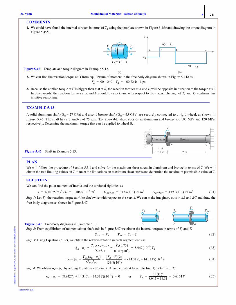
5 241Mechanics of Materials: Torsion of ShaftsM. VablePr
inte
d fr
om: h
ttp://
ww
w.m
e.m
tu.e
du/~
mav
able
/MoM
2nd.
htm
COMMENTS1. We could have found the internal torques in terms of TA using the template shown in Figure 5.45a and drawing the torque diagram in
Figure 5.45b.
2. We can find the reaction torque at D from equilibrium of moment in the free body diagram shown in Figure 5.44d as:
3. Because the applied torque at C is bigger than that at B, the reaction torques at A and D will be opposite in direction to the torque at C.In other words, the reaction torques at A and D should by clockwise with respect to the x axis. The sign of TA and TD confirms thisintuitive reasoning.
EXAMPLE 5.13
A solid aluminum shaft (Gal = 27 GPa) and a solid bronze shaft (Gbr = 45 GPa) are securely connected to a rigid wheel, as shown inFigure 5.46. The shaft has a diameter of 75 mm. The allowable shear stresses in aluminum and bronze are 100 MPa and 120 MPa,respectively. Determine the maximum torque that can be applied to wheel B.
PLANWe will follow the procedure of Section 5.3.1 and solve for the maximum shear stress in aluminum and bronze in terms of T. We willobtain the two limiting values on T to meet the limitations on maximum shear stress and determine the maximum permissible value of T.
SOLUTIONWe can find the polar moment of inertia and the torsional rigidities as
(E1)Step 1: Let TA, the reaction torque at A, be clockwise with respect to the x axis. We can make imaginary cuts in AB and BC and draw thefree-body diagrams as shown in Figure 5.47.
Step 2: From equilibrium of moment about shaft axis in Figure 5.47 we obtain the internal torques in terms of TA and T.
(E2)Step 3: Using Equation (5.12), we obtain the relative rotation in each segment ends as
(E3)
(E4)
Step 4: We obtain by adding Equations (E3) and (E4) and equate it to zero to find TA in terms of T:
(E5)
(a) (b)
T
TAT
90 � TAT
�150 � TAT
A B C D
T2TT � T1 � T
T1 T2TT
T
Figure 5.45 Template and torque diagram in Example 5.12.
TD 90 240– TA– 60.72 in.·kips–= =
Aluminum
T
B CAx
0.75 m
Bronze
2 m Figure 5.46 Shaft in Example 5.13.
J π 0.075 m( )4 32⁄ 3.106 10× 6– m4= = GABJAB 83.87 103( ) N·m2= GBCJBC 139.8 103( ) N·m2=
A
TAT TABT
A
T
B
TBCTTAT
Figure 5.47 Free-body diagrams in Example 5.13.
TAB TA= TBC TA T–=
φB φA–TAB xB xA–( )
GABJAB-------------------------------
TA 0.75( )
83.87 103( )--------------------------- 8.942 10 6–( )TA= = =
φC φB–TBC xC xB–( )
GBCJBC-------------------------------
TA T–( ) 2( )
139.8 103( )---------------------------- 14.31TA 14.31T–( ) 10 6–( )= = =
φC φA–
φC φA– 8.942TA 14.31TA 14.31T–+( ) 10 6–( ) 0= = or TA14.31T
8.942 14.31+--------------------------------- 0.6154T= =
September, 2011

5 242Mechanics of Materials: Torsion of ShaftsM. VablePr
inte
d fr
om: h
ttp://
ww
w.m
e.m
tu.e
du/~
mav
able
/MoM
2nd.
htm
Step 5: We obtain the internal torques in terms of T by substituting Equation (E5) into Equation (E2):(E6)
The maximum shear stress in segment AB and BC can be found in terms of T using Equation (5.10) and noting that ρmax = 0.0375 mm.Using the limits on shear stress we obtain the limits on T as
(E7)
(E8)
The value of T that satisfies Equations (E7) and (E8) is the maximum value we seek.ANS.
COMMENTS1. The maximum torque is limited by the maximum shear stress in bronze. If we had a limitation on the rotation of the wheel, then we
could easily incorporate it by calculating φB from Equation (E3) in terms of T. 2. We could have solved this problem by the displacement method. In that case we would carry the rotation of the wheel φB as the
unknown. 3. We could have solved the problem by initially assuming that one of the materials reaches its limiting stress value, say aluminum. We
can then do our calculations and find the maximum stress in bronze, which would exceed the limiting value of 120 MPa. We wouldthen resolve the problem. The process, though correct, can become tedious as the number of limitations increases. Instead put offdeciding which limitation dictates the maximum value of the torque toward the end. In this way we need to solve the problem onlyonce, irrespective of the number of limitations.
EXAMPLE 5.14
A solid steel (G = 80 GPa) shaft is securely fastened to a hollow bronze (G = 40 GPa) shaft as shown in Figure 5.48. Determine the max-imum value of shear stress in the shaft and the rotation of the right end with respect to the wall.
PLANThe steel shaft and the bronze shaft can be viewed as two independent shafts. At equilibrium the sum of the internal torques on eachmaterial is equal to the applied torque. The compatibility equation follows from the condition that a radial line on steel and bronze willrotate by the same amount. Hence, the relative rotation is the same for each length segment. Solving the equilibrium equation and thecompatibility equation we obtain the internal torques in each material, from which the desired quantities can be found.
SOLUTIONWe can find the polar moments and torsional rigidities as
(E1)
(E2)
TAB 0.6154T= TBC 0.3846T–=
τAB( )maxTAB ρAB( )max
JAB------------------------------
0.6154T( ) 0.0375 m( )
3.106 10 6–( ) m4----------------------------------------------------- 100 106( ) N/m2= = = or T 13.46 103( ) N·m≤
τBC( )maxTBC ρBC( )max
JBC------------------------------
0.3846T( ) 0.0375 m( )
3.106 10 6–( ) m4----------------------------------------------------- 120 106( ) N/m2= = = or T 25.84 103( ) N·m≤
Tmax 13.4 kN·m.=
Figure 5.48 Composite shaft in Example 5.14.
75 kN-m
80 mm
120 mm
A
B
2 m
JSπ32------ 0.08 m( )4 4.02 10 6–( ) m4= = JBr
π32------ 0.12 m( )4 0.08 m( )4–[ ] 16.33 10 6–( ) m4= =
GSJS 321.6 103( ) N m2⋅= GBrJBr 653.2 103( ) N m2⋅=
September, 2011

5 243Mechanics of Materials: Torsion of ShaftsM. VablePr
inte
d fr
om: h
ttp://
ww
w.m
e.m
tu.e
du/~
mav
able
/MoM
2nd.
htm
Figure 5.49a shows the free body diagram after making an imaginary cut in AB. Figure 5.49b shows the decomposition of a compositeshaft as two homogenous shafts.
From Figure 5.49 we obtain the equilibrium equation,
(E3)Using Equation (5.12) we can write the relative rotation of section at B with respect to A for the two material as
(E4)
(E5)
Equating Equations (E4) and (E5) we obtain(E6)
Solving Equations (E3) and (E4) for the internal torques give
(E7)Substituting Equation (7) into Equation (4), we find
(E8)
ANS. The maximum torsional shear stress in each material can be found using Equation (5.10):
(E9)
(E10)
The maximum torsional shear stress is the larger of the two.ANS.
COMMENT1. The kinematic condition that all radial lines must rotate by equal amount for a circular shaft had to be explicitly enforced to obtain
Equations (E6). We could also have implicitly assumed this kinematic condition and developed formulas for composite shafts (see Problem5.49) as we did for homogenous shaft. We can then use these formulas to solve statically determinate and indeterminate problems (see Problem5.82) as we have done for homogenous shafts.
PROBLEM SET 5.3
Statically indeterminate shafts
5.63 A steel shaft (Gst = 12,000 ksi) and a bronze shaft (Gbr = 5600 ksi) are securely connected at B, as shown in Figure P5.63. Determinethe maximum torsional shear stress in the shaft and the rotation of the section at B if the applied torque T = 50 in.·kips.
Δφ Δφ
Δφ
TAB Ts TBr
Figure 5.49 (a) Free body diagram (b) Composite shaft as two homogenous shafts in Example 5.14.
75 kN-m
B
TAB(a) (b)
TAB Ts TBr+ 75 kN m⋅ 75 103( ) N m⋅= = =
Δφ φB φA–Ts xB xA–( )
GsJs---------------------------
Ts 2( )
321.6 103( )--------------------------- 6.219 10 6–( )Ts rad= = = =
Δφ φB φA–TBr 2( )
653.2 103( )--------------------------- 3.0619 10 6–( )TBr rad= = =
Ts 2.03TBr=
Ts 24.75 103( ) N m⋅= TBr 50.25 103( ) N m⋅=
φB φA– 6.219 10 6–( ) 24.75( ) 103( ) 0.1538 rad= =
φB φA– 0.1538 rad ccw=
τs( )max
Ts ρs( )max
Js----------------------- 24.75 103( ) N m⋅[ ] 0.04 m( )
4.02 10 6–( ) m4--------------------------------------------------------------------- 246.3 106( ) N/m2= = =
τBr( )max
TBr ρBr( )max
JBr----------------------------- 50.25 103( ) N m⋅[ ] 0.06 m( )
16.33 10 6–( ) m4--------------------------------------------------------------------- 184.6 106( ) N/m2= = =
τmax 246.3 MPa=
T
4 ft Figure P5.63
September, 2011

5 244Mechanics of Materials: Torsion of ShaftsM. VablePr
inte
d fr
om: h
ttp://
ww
w.m
e.m
tu.e
du/~
mav
able
/MoM
2nd.
htm
5.64 A steel shaft (Gst = 12,000 ksi) and a bronze shaft (Gbr = 5600 ksi) are securely connected at B, as shown in Figure P5.63. Determinethe maximum torsional shear strain and the applied torque T if the section at B rotates by an amount of 0.02 rad.
5.65 Two hollow aluminum shafts (G = 10,000 ksi) are securely fastened to a solid aluminum shaft and loaded as shown Figure P5.65. IfT = 300 in.·kips, determine (a) the rotation of the section at C with respect to the wall at A; (b) the shear strain at point E. Point E is on theinner surface of the shaft.
5.66 Two hollow aluminum shafts (G = 10,000 ksi) are securely fastened to a solid aluminum shaft and loaded as shown Figure P5.65.The torsional shear strain at point E which is on the inner surface of the shaft is –250 μ. Determine the rotation of the section at C and theapplied torque T that produced this shear strain.
5.67 Two solid circular steel shafts (Gst = 80 GPa) and a solid circular bronze shaft (Gbr = 40 GPa) are securely connected by a coupling atC as shown in Figure P5.67. A torque of T = 10 kN·m is applied to the rigid wheel B. If the coupling plates cannot rotate relative to oneanother, determine the angle of rotation of wheel B due to the applied torque.
5.68 Two solid circular steel shafts (Gst = 80 GPa) and a solid circular bronze shaft (Gbr = 40 GPa) are connected by a coupling at C asshown in Figure P5.67. A torque of T = 10 kN·m is applied to the rigid wheel B. If the coupling plates can rotate relative to one another by0.5° before engaging, then what will be the angle of rotation of wheel B?
5.69 A solid steel shaft (G = 80 GPa) is securely fastened to a solid bronze shaft (G = 40 GPa) that is 2 m long, as shown in Figure P5.69.If Text = 10 kN · m, determine (a) the magnitude of maximum torsional shear stress in the shaft; (b) the rotation of the section at 1 m from theleft wall.
5.70 A solid steel shaft (G = 80 GPa) is securely fastened to a solid bronze shaft (G = 40 GPa) that is 2 m long, as shown in Figure P5.69.If the section at B rotates by 0.05 rad, determine (a) the maximum torsional shear strain in the shaft; (b) the applied torque Text.
5.71 Two shafts with shear moduli G1 = G and G2 = 2G are securely fastened at section B, as shown in Figure P5.71. In terms of Text, L, G,and d, find the magnitude of maximum torsional shear stress in the shaft and the rotation of the section at B.
24 in 24 in
T
36 in Figure P5.65
T � 10 kN�m
5 m 3 m Figure P5.67
TextTT
2 m1 m Figure P5.69
AAAAA
TextTT
2.5L Figure P5.71
September, 2011

5 245Mechanics of Materials: Torsion of ShaftsM. VablePr
inte
d fr
om: h
ttp://
ww
w.m
e.m
tu.e
du/~
mav
able
/MoM
2nd.
htm
5.72 A uniformly distributed torque of q in.·lb/in. is applied to the entire shaft, as shown in Figure P5.72. In addition to the distributedtorque a concentrated torque of T = 3qL in.·lb is applied at section B. Let the shear modulus be G and the radius of the shaft r. In terms of q,L, G, and r determine (a) the rotation of the section at B; (b) the magnitude of maximum torsional shear stress in the shaft.
Design problems
5.73 A steel shaft (Gst = 80 GPa) and a bronze shaft (Gbr = 40 GPa) are securely connected at B, as shown in Figure P5.69. The magnitudeof maximum torsional shear stresses in steel and bronze are to be limited to 160 MPa and 60 MPa, respectively. Determine the maximumallowable torque Text to the nearest kN·m that can act on the shaft.
5.74 A steel shaft (Gst = 80 GPa) and a bronze shaft (Gbr = 40 GPa) are securely connected at B, as shown in Figure P5.74. The magnitudeof maximum torsional shear stresses in steel and bronze are to be limited to 160 MPa and 60 MPa, respectively, and the rotation of section Bis limited to 0.05 rad. (a) Determine the maximum allowable torque T to the nearest kN·m that can act on the shaft if the diameter of theshaft is d = 100 mm. (b) What are the magnitude of maximum torsional shear stress and the maximum rotation in the shaft corresponding tothe answer in part (a)?
5.75 A steel shaft (Gst = 80 GPa) and a bronze shaft (Gbr = 40 GPa) are securely connected at B, as shown in Figure P5.74. The magnitudeof maximum torsional shear stresses in steel and bronze are to be limited to 160 MPa and 60 MPa, respectively, and the rotation of section Bis limited to 0.05 rad. (a) Determine the minimum diameter d of the shaft to the nearest millimeter if the applied torque T = 20 kN · m. (b)What are the magnitude of maximum torsional shear stress and the maximum rotation in the shaft corresponding to the answer in part (a)?
5.76 The solid steel shaft shown in Figure P5.76 has a shear modulus of elasticity G = 80 GPa and an allowable torsional shear stress of60 MPa. The allowable rotation of any section is 0.03 rad. The applied torques on the shaft are T1 = 10 kN·m and T2 = 25 kN· m. Determine(a) the minimum diameter d of the shaft to the nearest millimeter; (b) the magnitude of maximum torsional shear stress in the shaft and themaximum rotation of any section.
5.77 The diameter of the shaft shown in Figure P5.76 d = 80 mm. Determine the maximum values of the torques T1 and T2 to the nearestkN·m that can be applied to the shaft.
Composite Shafts
5.78 An aluminum tube and a copper tube, each having a thickness of 5 mm, are securely fastened to two rigid bars, as shown in FigureP5.78. The bars force the tubes to rotate by equal angles. The two tubes are 1.5 m long, and the mean diameters of the aluminum and coppertubes are 125 mm and 50 mm, respectively. The shear moduli for aluminum and copper are Gal = 28 GPa and Gcu = 40 GPa. Under the
LLB
22LL
q in�lb/in3qL inL �lb
Figure P5.72
TextTT
1.5 m3 m Figure P5.74
T1 T2TT
B C
d
2.5 m1.5 m1 m
Figure P5.76
September, 2011

5 246Mechanics of Materials: Torsion of ShaftsM. VablePr
inte
d fr
om: h
ttp://
ww
w.m
e.m
tu.e
du/~
mav
able
/MoM
2nd.
htm
action of the applied couple section B of the two tubes rotates by an angle of 0.03 rad Determine (a) the magnitude of maximum torsionalshear stress in aluminum and copper; (b) the magnitude of the couple that produced the given rotation.
5.79 Solve Problem 5.78 using Equations (5.18a) and (5.18b).
5.80 An aluminum tube and a copper tube, each having a thickness of 5 mm, are securely fastened to two rigid bars, as shown in FigureP5.78. The bars force the tubes to rotate by equal angles. The two tubes are 1.5 m long and the mean diameters of the aluminum and coppertubes are 125 mm and 50 mm, respectively. The shear moduli for aluminum and copper are Gal = 28 GPa and Gcu = 40 GPa. The applied cou-ple on the tubes shown in Figure P5.78 is 10 kN·m. Determine (a) the magnitude of maximum torsional shear stress in aluminum and cop-per; (b) the rotation of the section at B.
5.81 Solve Problem 5.80 using Equations (5.18a) and (5.18b).
5.82 Solve Example 5.14 using Equations (5.18a) and (5.18b).
5.83 The composite shaft shown in Figure P5.83 is constructed from aluminum (Gal = 4000 ksi), bronze (Gbr = 6000 ksi), and steel(Gst = 12,000 ksi). (a) Determine the rotation of the free end with respect to the wall. (b) Plot the torsional shear strain and the shear stressacross the cross section
5.84 Solve Problem 5.83 using Equations (5.18a) and (5.18b).
5.85 If T = 1500 N · m in Figure P5.85, determine (a) the magnitude of maximum torsional shear stress in cast iron and copper; (b) therotation of the section at D with respect to the section at A.
A
B
F
Aluminum
Copper
F
Figure P5.78
25 in
30 in�kips
2 in1.5 in
Steel BronzeAluminum Figure P5.83
500 mm 150 mm 400 mm
A B CD
TT
Figure P5.85
September, 2011

5 247Mechanics of Materials: Torsion of ShaftsM. VablePr
inte
d fr
om: h
ttp://
ww
w.m
e.m
tu.e
du/~
mav
able
/MoM
2nd.
htm
Shafts on multiple axis
5.86 Two steel (G = 80 GPa) shafts AB and CD of diameters 40 mm are connected with gears as shown in Figure P5.86. The radii of gears at Band C are 250 mm and 200 mm, respectively. The bearings at E and F offer no torsional resistance to the shafts. If an input torque of Text = 1.5 kN.mis applied at D, determine (a) the maximum torsional shear stress in AB; (b) the rotation of section at D with respect to the fixed section at A.
5.87 Two steel (G = 80 GPa) shafts AB and CD of diameters 40 mm are connected with gears as shown in Figure P5.86. The radii ofgears at B and C are 250 mm and 200 mm, respectively. The bearings at E and F offer no torsional resistance to the shafts. The allowableshear stress in the shafts is 120 MPa. Determine the maximum torque T that can be applied at section D.
5.88 Two steel (G = 80 GPa) shafts AB and CDE of 1.5 in. diameters are connected with gears as shown in Figure P5.88. The radii of gears at Band D are 9 in. and 5 in., respectively. The bearings at F, G, and H offer no torsional resistance to the shafts. If an input torque of Text = 800 ft.lb isapplied at D, determine (a) the maximum torsional shear stress in AB; (b) the rotation of section at E with respect to the fixed section at C.
5.89 Two steel (G = 80 GPa) shafts AB and CD of 60 mm diameters are connected with gears as shown in Figure P5.89. The radii of gears at Band D are 175 mm and 125 mm, respectively. The bearings at E and F offer no torsional resistance to the shafts. If an input torque of Text = 2 kN.mis applied, determine (a) the maximum torsional shear stress in AB; (b) the rotation of section at D with respect to the fixed section at C.
5.90 Two steel (G = 80 GPa) shafts AB and CD of 60 mm diameters are connected with gears as shown in Figure P5.89. The radii ofgears at B and D are 175 mm and 125 mm, respectively. The bearings at E and F offer no torsional resistance to the shafts. The allowableshear stress in the shafts is 120 MPa. What is the maximum torque T that can be applied?
5.91 Two steel (G = 80 GPa) shafts AB and CD of equal diameters d are connected with gears as shown in Figure P5.89. The radii ofgears at B and D are 175 mm and 125 mm, respectively. The bearings at E and F offer no torsional resistance to the shafts. The allowableshear stress in the shafts is 120 MPa and the input torque is T = 2 kN.m. Determine the minimum diameter d to the nearest millimeter.
Figure P5.86
Text
D
A B
C E
F
1.2 m
1.5 m
Figure P5.88
Text
E
A B
D H
F
4 ft
5 ft
C G
Figure P5.89
Text
1.5 m
C F
A E B
D
September, 2011

5 248Mechanics of Materials: Torsion of ShaftsM. VablePr
inte
d fr
om: h
ttp://
ww
w.m
e.m
tu.e
du/~
mav
able
/MoM
2nd.
htm
Stress concentration5.92 The allowable shear stress in the stepped shaft shown Figure P5.92 is 17 ksi. Determine the smallest fillet radius that can be used atsection B. Use the stress concentration graphs given in Section C.4.3.
5.93 The fillet radius in the stepped shaft shown in Figure P5.93 is 6 mm. Determine the maximum torque that can act on the rigid wheelif the allowable shear stress is 80 MPa and the modulus of rigidity is 28 GPa. Use the stress concentration graphs given in Section C.4.3.
5.4* TORSION OF THIN-WALLED TUBES
The sheet metal skin on a fuselage, the wing of an aircraft, and the shell of a tall building are examples in which a body can beanalyzed as a thin-walled tube. By thin wall we imply that the thickness t of the wall is smaller by a factor of at least 10 in com-parison to the length b of the biggest line that can be drawn across two points on the cross section, as shown in Figure 5.50a. Bya tube we imply that the length L is at least 10 times that of the cross-sectional dimension b.We assume that this thin-walled tube is subjected to only torsional moments.
The walls of the tube are bounded by two free surfaces, and hence by the symmetry of shear stresses the shear stress in thenormal direction τxn must go to zero on these bounding surfaces, as shown in Figure 5.50b.This does not imply that τxn is zero inthe interior. However, because the walls are thin, we approximate τxn as zero everywhere. The normal stress σxx would be equiv-alent to an internal axial force or an internal bending moment. Since there is no external axial force or bending moment, weapproximate the value of σxx as zero.
Figure 5.50b shows that the only nonzero stress component is τxs. It can be assumed uniform in the n direction because thetube is thin. Figure 5.50c shows a free-body diagram of a differential element with an imaginary cut through points A and B. Byequilibrium of forces in the x direction we obtain
(5.24a)
(5.24b)
(5.24c)
Figure P5.92CBA
2 in
T � 2.5 in�kips
1 in
Figure P5.93
60 mm
48 mmT
0.9 m 0.75 m 1.0 m
L
b
T
T
Figure 5.50 (a) Torsion of thin-walled tubes. (b) Deducing stress behavior in thin-walled tubes. (c) Deducing constant shear flow in thin-walled tubes.
b 10t>L >10b
s
�xs�
Free surface,�nx � � 0
Zero because ofthin body and �xn� � �nx�Zero because
there is no axialforce or bendingmoment
Free surface,�nx � � 0
T
(a) (b)
�B�
AAAA
B�B�
�A�
�A�
dx tAt
tBt
(c)
τA tA dx( ) τB tB dx( )=
τAtA τBtB=
qA qB=
September, 2011

5 249Mechanics of Materials: Torsion of ShaftsM. VablePr
inte
d fr
om: h
ttp://
ww
w.m
e.m
tu.e
du/~
mav
able
/MoM
2nd.
htm
The quantity is called shear flow5 and has units of force per unit length. Equation (5.24c) shows that shear flow is uni-form at a given cross section.
We can replace the shear stresses (shear flow) by an equivalent internal torque, as shown in Figure 5.51. The line OC is per-pendicular to the line of action of the force dV, which is in the tangent direction to the arc at that point. Noting that the shear flowis a constant, we take it outside the integral sign,
(5.25)
We thus obtain
(5.26)
where T is the internal torque at the section containing the point at which the shear stress is to be calculated, AE is the areaenclosed by the centerline of the tube, and t is the thickness at the point where the shear stress is to be calculated.
The thickness t can vary with different points on the cross section provided the assumption of thin-walled is not violated. Ifthe thickness varies, then the shear stress will not be constant on the cross section, even though the shear flow is constant.
EXAMPLE 5.15
A semicircular thin tube is subjected to torques as shown in Figure 5.52. Determine: (a) The maximum torsional shear stress in the tube.(b) The torsional shear stress at point O. Show the results on a stress cube.
PLANFrom Equation 5.26 we know that the maximum torsional shear stress will exist in a section where the internal torque is maximum andthe thickness minimum. To determine the maximum internal torque, we make cuts in AB, BC, and CD and draw free-body diagrams bytaking the right part of each cut to avoid calculating the wall reaction.
SOLUTION
5This terminology is from fluid mechanics, where an incompressible ideal fluid has a constant flow rate in a channel.
q τxst=
T dT∫° q h ds( )∫° q 2 dAE∫° 2qAE= = = = or q T2AE---------=
τxsT
2tAE-----------=
h � perpendicular distance fromorigin to force dF
Area enclosed AE
ddVV � q ds
dT � h dV � h(q ds)
OAB � dAE
dsB
CO O
dAE � (h ds)12
x x
T
A
Figure 5.51 Equivalency of internal torque and shear stress (flow).
x
5 in
O
Cross section
xAB O
CD
70 in�kips50 in�kips
20 in�kips
1 in8
3 in16
Figure 5.52 Thin-walled tube in Example 5.15.
September, 2011

5 250Mechanics of Materials: Torsion of ShaftsM. VablePr
inte
d fr
om: h
ttp://
ww
w.m
e.m
tu.e
du/~
mav
able
/MoM
2nd.
htm
Figure 5.53 shows the free-body diagrams after making an imaginary cut and taking the right part.
(a) The maximum torque is in AB and the minimum thickness is The enclosed area is From
Equation 5.26 we obtain
(E1)
ANS.
(b) At point O the internal torque is TBC and t = in. We obtain the shear stress at O as
(E2)
ANS.Figure 5.54 shows part of the tube between sections B and C. Segment BO would rotate counterclockwise with respect to segment OC. Theshear stress must be opposite to this possible motion and hence in the clockwise direction, as shown. The direction on the other surfaces canbe drawn using the observation that the symmetric pair of shear stress components either point toward the corner or away from it.
COMMENT1. The shear flow in the cross-section containing point O is a constant over the entire cross-section. The magnitude of torsional shear
stress at point O however will be two-thirds that of the value of the shear stress in the circular part of the cross-section because of thevariation in wall thickness.
PROBLEM SET 5.4
Torsion of thin-walled tubes
5.94 Calculate the magnitude of the maximum torsional shear stress if the cross section shown in Figure P5.94 is subjected to a torqueT = 100 in.·kips.
TABT � 50 � 70 � 20 � 0
TABT � 40 in�kips
TABT70 in �kips
50 in �kips20 in �kips
T � 20 � 0
TCD 20 in�kips
TCD 20 in �kips
�T � 50 � � 0
TBCT � 30 in�kips
TBCT 50 in �kips20 in �kips
Figure 5.53 Internal torque calculations in Example 5.15.
18--- in. AE π 5 in.( )2 2⁄ 12.5π in.2.= =
τmax40π in.· kips( )
12.5π in.2( ) 18--- in.( )
---------------------------------------------=
τmax 25.6 ksi=3
16------
τO30π in.· kips( )
12.5π in.2( ) 316------ in.( )
-----------------------------------------------=
τO 12.8 ksi=
x
�O
BC
70 in�kips50 in�kips
O�O
x Figure 5.54 Direction of shear stress in Example 5.15.
t �
R � 2 inR � 2 in
4 in
14
in
Figure P5.94
September, 2011

5 251Mechanics of Materials: Torsion of ShaftsM. VablePr
inte
d fr
om: h
ttp://
ww
w.m
e.m
tu.e
du/~
mav
able
/MoM
2nd.
htm
5.95 Calculate the magnitude of the maximum torsional shear stress if the cross section shown in Figure P5.95 is subjected to a torqueT = 900 N·m.
5.96 Calculate the magnitude of the maximum torsional shear stress if the cross section shown in Figure P5.96 is subjected to a torqueT = 15 kN·m.
5.97 A tube of uniform thickness t and cross section shown in Figure P5.97 has a torque T applied to it. Determine the maximum torsionalshear stress in terms of t, a, and T.
5.98 A tube of uniform thickness t and cross section shown in Figure P5.98 has a torque T applied to it. Determine the maximum torsionalshear stress in terms of t, a, and T.
5.99 A tube of uniform thickness t and cross section shown in Figure P5.99 has a torque T applied to it. Determine the maximum torsionalshear stress in terms of t, a, and T.
5.100 The tube of uniform thickness t shown in Figure P5.100 has a torque T applied to it. Determine the maximum torsional shear stressin terms of t, a, b, and T.
Figure P5.95
t � 3 mm
t � 5 mm
t � 6 mm
R � 50 mm
100 mm
Figure P5.96
t � 6 mm
100 mm
100 mm
60�60�
a Figure P5.97
a
a Figure P5.98
a
Figure P5.99
b
a
Figure P5.100
September, 2011

5 252Mechanics of Materials: Torsion of ShaftsM. VablePr
inte
d fr
om: h
ttp://
ww
w.m
e.m
tu.e
du/~
mav
able
/MoM
2nd.
htm
5.101 A hexagonal tube of uniform thickness is loaded as shown in Figure P5.101. Determine the magnitude of the maximum torsionalshear stress in the tube
5.102 A rectangular tube is loaded as shown in Figure P5.102. Determine the magnitude of the maximum torsional shear stress.
5.103 The three tubes shown in Problems 5.97 through 5.99 are to be compared for the maximum torque-carrying capability, assumingthat all tubes have the same thickness t, the maximum torsional shear stress in each tube can be τ, and the amount of material used in thecross section of each tube is A. (a) Which shape would you use? (b) What is the percentage torque carried by the remaining two shapes interms of the most efficient structural shape?
5.5* CONCEPT CONNECTOR
Like so much of science, the theory of torsion in shafts has a history filled with twists and turns. Sometimes experiments led theway; sometimes logic pointed to a solution. As so often, too, serendipity guided developments. The formulas were developedempirically, to meet a need—but not in the mechanics of materials. Instead, a scientist had a problem to solve in electricity andmagnetism, and torsion helped him measure the forces. It was followed with an analytical development of the theory for circularand non-circular shaft cross sections that stretched over a hundred years. The description of the history concludes with an experi-mental technique used in the calculation of torsional rigidity, even for shafts of arbitrary shapes.
5.5.1 History: Torsion of Shafts
It seems fitting that developments begin with Charles-Augustin Coulomb (Figure 5.55). Coulomb, who firstdifferentiated shear stress from normal stress (see Section 1.6.1), also studied torsion, in which shear stress is the dominantcomponent. In 1781 Coulomb started his research in electricity and magnetism. To measure the small forces involved, hedevised a very sensitive torsion balance. A weight was suspended by a wire, and a pointer attached to the weight indicated thewire’s angular rotation.
The design of this torsion balance led Coulomb to investigate the resistance of a wire in torsion. He assumed that the resis-tance torque (or internal torque T) in a twisted wire is proportional to the angle of twist φ. To measure the changes, he twisted the
T4TT � �mT3TT � �m
T2TT �mT1 1000 N�m
100 mm
t � 4 mm Figure P5.101
Figure P5.102
6 in
4 in
T4TT � 2 in�kips T3TT � 3 in�kips T1 � 2 in�kips
Figure 5.55 Charles-Augustin Coulomb.
September, 2011
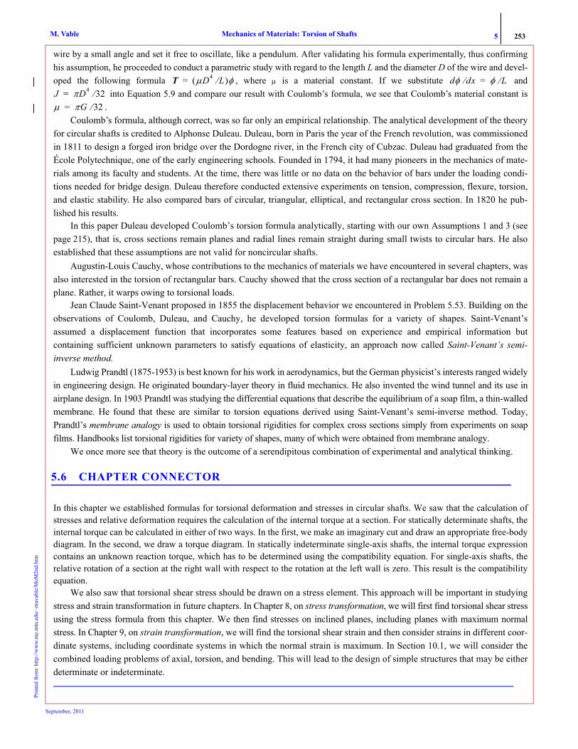
5 253Mechanics of Materials: Torsion of ShaftsM. VablePr
inte
d fr
om: h
ttp://
ww
w.m
e.m
tu.e
du/~
mav
able
/MoM
2nd.
htm
wire by a small angle and set it free to oscillate, like a pendulum. After validating his formula experimentally, thus confirminghis assumption, he proceeded to conduct a parametric study with regard to the length L and the diameter D of the wire and devel-oped the following formula , where μ is a material constant. If we substitute and
into Equation 5.9 and compare our result with Coulomb’s formula, we see that Coulomb’s material constant is.
Coulomb’s formula, although correct, was so far only an empirical relationship. The analytical development of the theoryfor circular shafts is credited to Alphonse Duleau. Duleau, born in Paris the year of the French revolution, was commissionedin 1811 to design a forged iron bridge over the Dordogne river, in the French city of Cubzac. Duleau had graduated from theÉcole Polytechnique, one of the early engineering schools. Founded in 1794, it had many pioneers in the mechanics of mate-rials among its faculty and students. At the time, there was little or no data on the behavior of bars under the loading condi-tions needed for bridge design. Duleau therefore conducted extensive experiments on tension, compression, flexure, torsion,and elastic stability. He also compared bars of circular, triangular, elliptical, and rectangular cross section. In 1820 he pub-lished his results.
In this paper Duleau developed Coulomb’s torsion formula analytically, starting with our own Assumptions 1 and 3 (seepage 215), that is, cross sections remain planes and radial lines remain straight during small twists to circular bars. He alsoestablished that these assumptions are not valid for noncircular shafts.
Augustin-Louis Cauchy, whose contributions to the mechanics of materials we have encountered in several chapters, wasalso interested in the torsion of rectangular bars. Cauchy showed that the cross section of a rectangular bar does not remain aplane. Rather, it warps owing to torsional loads.
Jean Claude Saint-Venant proposed in 1855 the displacement behavior we encountered in Problem 5.53. Building on theobservations of Coulomb, Duleau, and Cauchy, he developed torsion formulas for a variety of shapes. Saint-Venant’sassumed a displacement function that incorporates some features based on experience and empirical information butcontaining sufficient unknown parameters to satisfy equations of elasticity, an approach now called Saint-Venant’s semi-inverse method.
Ludwig Prandtl (1875-1953) is best known for his work in aerodynamics, but the German physicist’s interests ranged widelyin engineering design. He originated boundary-layer theory in fluid mechanics. He also invented the wind tunnel and its use inairplane design. In 1903 Prandtl was studying the differential equations that describe the equilibrium of a soap film, a thin-walledmembrane. He found that these are similar to torsion equations derived using Saint-Venant’s semi-inverse method. Today,Prandtl’s membrane analogy is used to obtain torsional rigidities for complex cross sections simply from experiments on soapfilms. Handbooks list torsional rigidities for variety of shapes, many of which were obtained from membrane analogy.
We once more see that theory is the outcome of a serendipitous combination of experimental and analytical thinking.
5.6 CHAPTER CONNECTOR
In this chapter we established formulas for torsional deformation and stresses in circular shafts. We saw that the calculation ofstresses and relative deformation requires the calculation of the internal torque at a section. For statically determinate shafts, theinternal torque can be calculated in either of two ways. In the first, we make an imaginary cut and draw an appropriate free-bodydiagram. In the second, we draw a torque diagram. In statically indeterminate single-axis shafts, the internal torque expressioncontains an unknown reaction torque, which has to be determined using the compatibility equation. For single-axis shafts, therelative rotation of a section at the right wall with respect to the rotation at the left wall is zero. This result is the compatibilityequation.
We also saw that torsional shear stress should be drawn on a stress element. This approach will be important in studyingstress and strain transformation in future chapters. In Chapter 8, on stress transformation, we will first find torsional shear stressusing the stress formula from this chapter. We then find stresses on inclined planes, including planes with maximum normalstress. In Chapter 9, on strain transformation, we will find the torsional shear strain and then consider strains in different coor-dinate systems, including coordinate systems in which the normal strain is maximum. In Section 10.1, we will consider thecombined loading problems of axial, torsion, and bending. This will lead to the design of simple structures that may be eitherdeterminate or indeterminate.
T μD4 L⁄( )φ= dφ dx⁄ φ L⁄=J πD4 32⁄=μ πG 32⁄=
September, 2011

254 2 Torsion of ShaftsPOINTS AND FORMULAS TO REMEMBER
• Our theory describing the torsion of shafts is limited to: (1) slender shafts of circular cross sections; and (2) regionsaway from the neighborhood of stress concentration. The variation in cross sections and external torques is gradual.
(5.1) (5.2) small strain (5.3)
• where T is the internal torque that is positive counterclockwise with respect to the outward normal to the imaginarycut surface, φ is the angle of rotation of the cross section that is positive counterclockwise with respect to the x axis,τxθ and γxθ are the torsional shear stress and strain in polar coordinates, and ρ is the radial coordinate of the pointwhere shear stress and shear strain are defined.
• Equations (5.1), (5.2), and (5.3) are independent of material model. • Torsional shear strain varies linearly with radial coordinate across the cross section.• Torsional shear strain is maximum at the outer surface of the shaft.• The formulas below are valid for shafts with material that is linear, elastic, and isotropic and has a homogeneous
cross section:
(5.9) (5.10) (5.12)
• where G is the shear modulus of elasticity, and J is the polar moment of the cross section given by, Ro and Ri being the outer and inner radii of a hollow shaft.
• The quantity GJ is called torsional rigidity.• If T, G, or J change with x, we find the relative rotation of a cross section by integration of Equation (5.9).• If T, G, and J do not change between x1 and x2, we use Equation (5.12) to find the relative rotation of a cross section. • Torsional shear stress varies linearly with radial coordinate across the homogeneous cross section, reaching a maxi-
mum value on the outer surface of the shaft.
T ρτxθ AdA
∫= φ φ x( )= γxθ ρxd
dφ=
xddφ T
GJ-------= τxθ
TρJ
-------= φ2 φ1–T x2 x1–( )
GJ------------------------=
J π 2⁄( ) Ro4 Ri
4–( )=
Related Documents