Workshop manual Chapter F rev. C Heating, ventilation and AC 26.11.10 © THINK Global AS Page 1 of 34 Chapter F Heating, ventilation and AC F.1 Air Conditioning 3 F.1.1 Heating without aircoditioning (AC) 3 F.1.2 Heating With AC 4 F.1.3 OPERATION - REFRIGERANT CIRCUIT 5 F.2 Heating 6 F.2.1 Draining 6 F.2.2 Filling 6 F.2.3 Bleeding 6 F.2.4 Reduction valve 9 F.2.5 Fasten the coolant hose 9 F.3 Reservoir 9 F.3.1 Disassembling 9 F.3.2 Assembling 10 F.4 Hoses 10 F.4.1 Disassembling 10 F.4.2 Replacing hoses 10 F.4.3 Assembling 10 F.5 Pump 11 F.5.1 Disassembling 11 F.5.2 Assembling 11 F.6 Fluid heater 11 F.6.1 Disassembling 11 F.6.2 Assembling 12 F.7 Fresh air intake filter 13 F.7.1 Intake filter replacement 13 F.8 CDCM 13 F.8.1 Disassembling 13 F.8.2 Assembling 14 F.9 Heater 14 F.9.1 Disassembling of the control panel 14 F.9.2 Assembling 16 F.9.3 Disassembling – tube Assembly 16 F.9.4 Assembling 16 F.9.5 Disassembling– heater element 17 F.9.6 Assembling 17 F.9.7 Disassembling– blower 17 F.9.8 Assembling 18 F.9.9 Disassembling – blower resistor 18

Welcome message from author
This document is posted to help you gain knowledge. Please leave a comment to let me know what you think about it! Share it to your friends and learn new things together.
Transcript

Workshop manual Chapter F rev. C
Heating, ventilation and AC 26.11.10
© THINK Global AS Page 1 of 34
Chapter F
Heating, ventilation and AC
F.1 Air Conditioning 3
F.1.1 Heating without aircoditioning (AC) 3
F.1.2 Heating With AC 4
F.1.3 OPERATION - REFRIGERANT CIRCUIT 5
F.2 Heating 6
F.2.1 Draining 6
F.2.2 Filling 6
F.2.3 Bleeding 6
F.2.4 Reduction valve 9
F.2.5 Fasten the coolant hose 9
F.3 Reservoir 9
F.3.1 Disassembling 9
F.3.2 Assembling 10
F.4 Hoses 10
F.4.1 Disassembling 10
F.4.2 Replacing hoses 10
F.4.3 Assembling 10
F.5 Pump 11
F.5.1 Disassembling 11
F.5.2 Assembling 11
F.6 Fluid heater 11
F.6.1 Disassembling 11
F.6.2 Assembling 12
F.7 Fresh air intake filter 13
F.7.1 Intake filter replacement 13
F.8 CDCM 13
F.8.1 Disassembling 13
F.8.2 Assembling 14
F.9 Heater 14
F.9.1 Disassembling of the control panel 14
F.9.2 Assembling 16
F.9.3 Disassembling – tube Assembly 16
F.9.4 Assembling 16
F.9.5 Disassembling– heater element 17
F.9.6 Assembling 17
F.9.7 Disassembling– blower 17
F.9.8 Assembling 18
F.9.9 Disassembling – blower resistor 18
Workshop manual Chapter F rev. C
Heating, ventilation and AC 26.11.10
© THINK Global AS Page 2 of 34
F.9.10 Assembling 18
F.9.11 Disassembling – complete heater 19
F.9.12 Assembling 20
F.10 AC Air - Conditioning system 20
F.10.1 Working on AC system 20
F.10.2 Specifications 21
F.10.3 Leak test (gas sniffer and UV/transfluid) 22
F.10.4 Follow product instructions for the search appliance.Leak test by use of N2 Gas 22
F.10.5 AC system location 23
F.10.6 AC Static pressure test 23
F.11 Draining The AC system 24
F.11.1 Refilling of the AC system 25
F.11.2 Test of condenser function 25
F.11.3 AC perfomance temerature test 26
F.12 Condenser A/C removal 26
F.13 Assembling of the condenser 31
F.14 Expansion valve removal 31
F.15 Assembling of expansion valve 32
F.16 Replace A/C compressor 33
F.17 Assembling of the compressor 35

Workshop manual Chapter F rev. C
Heating, ventilation and AC 26.11.10
© THINK Global AS Page 3 of 34
F.1 Air Condition Generally
Turn off the ignition, make sure that the
traction battery is not charging and disconnect
the 12V battery before start working on the
heating circuit.
F.1.1 Heating without air condition (AC)
The heating circuit shares the reservoir with
the cooling circuit. Other than this there is no
connection between the two circuits.
FLUID HEATER
HEATER
RESERVOIR
PUMP
T-JOINT

Workshop manual Chapter F rev. C
Heating, ventilation and AC 26.11.10
© THINK Global AS Page 4 of 34
F.1.2 Heating With AC Climate control system is equipped with a
blend air type heater. Fresh air enters the
heater through the cowl grille and passes
through a plenum chamber with heater core
and cooling evaporator. The fluid heater and
AC hardware is located in the engine
compartment.
The heating circuit shares the reservoir with
the cooling circuit for PCU (Power Control Unit).
Other than this there is no connection between
the two circuits.
Cooling circuit consists of:
• Switch for enabling AC
• Compressor
• Evaporator (cooling surface)
• Accumulator and dryer
• Condenser Assembling
• Thermostatic expansion valve (TXV)
• Evaporator temperature sensor
(evaporator temperature control)
• A/C pressure transducer (monitoring
the pressure in the high side of the
refrigerant system)
• Cooling fan (cooling of condenser
process)
• Control unit with relays and fuses
Generally:
Turn off the ignition, make sure the traction
battery is not charging and disconnect the 12 V
battery before starting work on the heating
circuit.
Use approved personal protective
equipment when working on the cooling
circuit
WARNING
Beware of danger when working with
R-134a refrigerant!
Rapid evaporation of the liquid may cause
frostbite.
Vapours are heavier than air and can
cause suffocation by reducing oxygen
available for breathing
Condenser
COOLING EVAPORATOR
COMPRESSOR
THERMOSTAT
REGULATION VALVE
HEATER CORE
FLUID HEATER
PUMP
T-JOINT
RESERVOIR
INTERIOR AIR

Workshop manual Chapter F rev. C
Heating, ventilation and AC 26.11.10
© THINK Global AS Page 5 of 34
F.1.3 OPERATION - REFRIGERANT CIRCUIT
CAUTION: Liquid refrigerant is corrosive to metal
surfaces. Follow the operating instructions
supplied with the service equipment being
used.
• The refrigerant system must always be
evacuated before charging.
• Do not open the refrigerant system or
uncap a replacement component until
you are ready to service the system.
This will prevent contamination in the
system.
• Before connecting an open refrigerant
fitting, always install a new seal or
gasket. Coat the fitting and seal with
clean refrigerant oil before connecting.
Do not remove the sealing caps from a
replacement component until it is to be
installed.
• When installing a refrigerant hose, avoid
sharp bends that may restrict
refrigerant flow.
• Refrigerant oil will absorb moisture from
the atmosphere if left uncapped. Do not
open a container of refrigerant oil until
you are ready to use it. Replace the cap
on the oil container immediately after
using.
• Store refrigerant oil only in a clean,
airtight, and moisture-free container.
• Keep service tools and the work area
clean. Contamination of the refrigerant
system through careless work habits
must be avoided.
• Refrigerant in vapor form will in
combination with fire be dangerous to
breath. Do not smoke!

Workshop manual Chapter F rev. C
Heating, ventilation and AC 26.11.10
© THINK Global AS Page 6 of 34
F.2 Heating
F.2.1 Draining • Loosen the hose from the T-joint to the
pump, and let the coolant drain in a
suitable container.
NOTE: There will be some coolant left in the
system that may need to be drained when the
components have been removed out of the car.
Draining of the heating circuit is mainly
relevant when replacing hoses.
F.2.2 Filling • Fill coolant to the MAX label on the
reservoir and leave the cap off.
• Turn the ignition on so you hear the pumps
in the cooling circuit are running.
• Start the pump in the heating circuit by
turning the heater on (red area) and the
fan to position 1.
• Refill coolant in the reservoir gradually as
the level decreases.
• The heating circuit probably needs bleeding
after filling coolant (see below).
F.2.3 Bleeding Due to small level differences in the system it
can be difficult to bleed the heating circuit
properly.
With ignition on set the fan to position 1
Check that the pump starts. Check coolant
level in the reservoir.
A small amount of air bobbles in the system is
allowed. Listen to the sound of the pump. If
running smoothly and evenly the system has
been properly bleeded.
If this is not sufficient do the following:

Workshop manual Chapter F rev. C
Heating, ventilation and AC 26.11.10
© THINK Global AS Page 7 of 34
• Remove the air duct above the fluid heater
for easier access to the fluid heater and the
coolant hoses. The air duct is fastened with
one fastener.
• Disconnect the connector on the fluid
heater.
IMPORTANT: This is important because if
it is connected during the bleeding
process and the level is low the fluid
heater can be damaged.
Warning PCU Gen2!
Never disconnect cable for heater box
when the system is powered. This will
cause EPO(Emergency Power Off) The
condition will harm the PCU.
• Fill coolant to the MAX level on the
reservoir and leave the cap off.

Workshop manual Chapter F rev. C
Heating, ventilation and AC 26.11.10
© THINK Global AS Page 8 of 34
Attach the bleeding tool as shown in the
picture.
• Turn the ignition on (drive position), heater
on max and fan to position 1 so you hear
the pump in the cooling circuit is running.
• Check reservoir level and fill coolant if
necessary.
• Let the pump run until you hear it running
smoothly without any air left in the system.
TIP: When replacing the fluid heater it is
necessary to fill the new fluid heater with
coolant before installing it. This will make the
bleeding process easier and faster.
When the pump is running smoothly and all air
is out of the system the bleeding tool can be
disconnected in followed steps:
• Turn the ignition off (make sure the pump
is not running).
• Attach clamp pliers or other suitable tool.
• Disconnect the bleeding tool and connect
the coolant hose. Avoid without spilling
coolant as far as possible.
• Connect the signal connectors on the fluid
heater.
• Test the fluid heater and listen to the pump
if there is any air left in the system.
• Check the coolant level.
Workshop manual Chapter F rev. C
Heating, ventilation and AC 26.11.10
© THINK Global AS Page 9 of 34
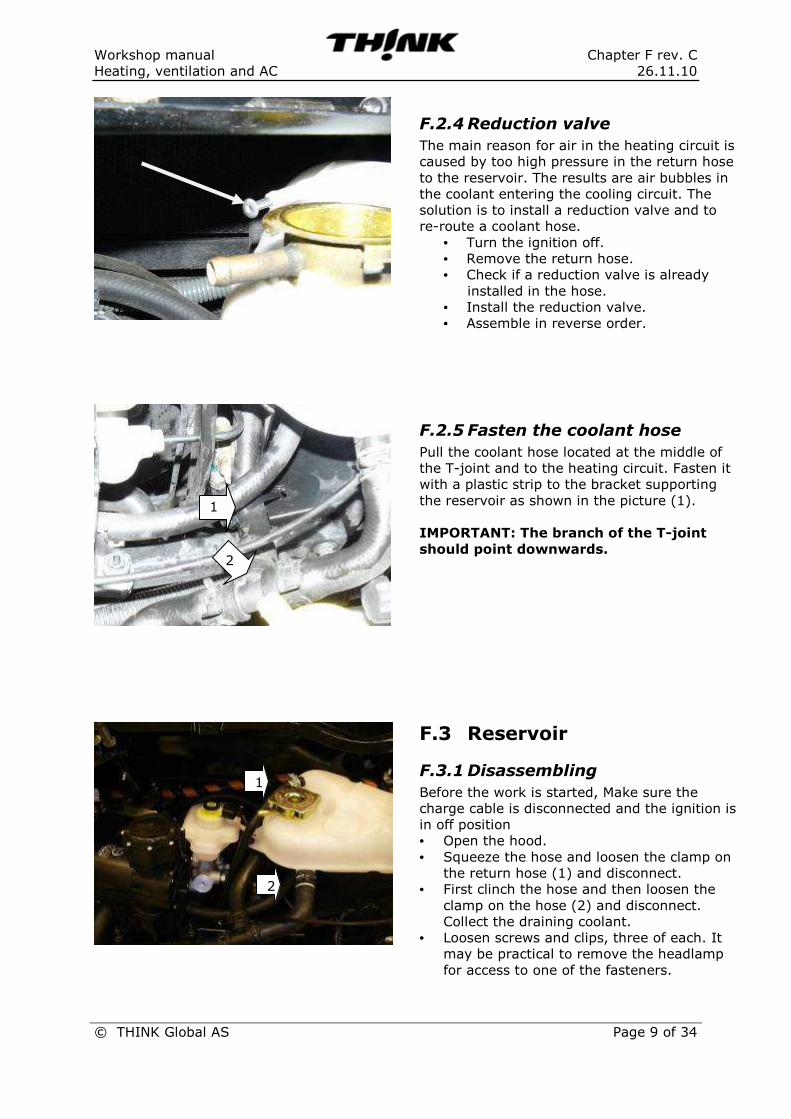
F.2.4 Reduction valve The main reason for air in the heating circuit is
caused by too high pressure in the return hose
to the reservoir. The results are air bubbles in
the coolant entering the cooling circuit. The
solution is to install a reduction valve and to
re-route a coolant hose.
• Turn the ignition off.
• Remove the return hose.
• Check if a reduction valve is already
installed in the hose.
• Install the reduction valve.
• Assemble in reverse order.
F.2.5 Fasten the coolant hose Pull the coolant hose located at the middle of
the T-joint and to the heating circuit. Fasten it
with a plastic strip to the bracket supporting
the reservoir as shown in the picture (1).
IMPORTANT: The branch of the T-joint
should point downwards.
F.3 Reservoir
F.3.1 Disassembling Before the work is started, Make sure the
charge cable is disconnected and the ignition is
in off position
• Open the hood.
• Squeeze the hose and loosen the clamp on
the return hose (1) and disconnect.
• First clinch the hose and then loosen the
clamp on the hose (2) and disconnect.
Collect the draining coolant.
• Loosen screws and clips, three of each. It
may be practical to remove the headlamp
for access to one of the fasteners.
1
2
2
1

Workshop manual Chapter F rev. C
Heating, ventilation and AC 26.11.10
© THINK Global AS Page 10 of 34
F.3.2 Assembling • Assembling in reverse order.
• Fill coolant.
• See section F1.3 regarding bleeding of the
system.
F.4 Hoses
F.4.1 Disassembling • First drain the heating circuit for coolant.
• Loosen the clamps and push it back.
• Remove the hose.
TIP: To collect the coolant spilling out, place a
drain container with a large opening under the
vehicle.
You can also drain the cooling circuit before
hoses are disconnected. See section F.1.1.
F.4.2 Replacing hoses Drain the heating circuit for coolant as
described in section F.1.2 before any defect
hoses are replaced.
F.4.3 Assembling • Attach the new hose. NOTE! Check date
code (se picture marked with arrow).
• Fasten the hose with the clamp.
• Fill coolant.
• Bleed the system. See section F.1.3.

Workshop manual Chapter F rev. C
Heating, ventilation and AC 26.11.10
© THINK Global AS Page 11 of 34
F.5 Pump
F.5.1 Disassembling Before the work is started, Make sure the
charge cable is disconnected and the ignition is
in off position
• Disconnect the 12V battery.
• Loosen the contact (see picture).
• Push the pump out of its rubber sleeve.
• Squeeze the hoses and disconnect them.
F.5.2 Assembling Assembling in reverse order.
Refill coolant if necessary and bleed the
heating circuit (see section F.1.3).
F.6 Fluid heater
F.6.1 Disassembling Before the work is started, Make sure the
charge cable is disconnected and the ignition is
in off position
• Open the hood.
• Disconnect the 12V battery.
• Disconnect the traction battery (see
chapter C).
• Remove the air duct above the fluid heater.
The air duct is fastened with one fastener.

Workshop manual Chapter F rev. C
Heating, ventilation and AC 26.11.10
© THINK Global AS Page 12 of 34
• Disconnect the connector (1) and grounding
cable (2).
• Squeeze the hoses suitable pliers and
loosen the clamps (3). Collect the draining
coolant.
• Loosen the pump with rubber sleeve from
the bracket (4).
• Disconnect the connector to the fluid
heater.
• Loosen the fluid heater bracket and remove
it.
F.6.2 Assembling Assemble in reverse order.
Fill coolant and bleed the heating circuit if
necessary.
Tightening torques:
Fluid heater to bracket = 7 Nm
4
3 3
2
1
Workshop manual Chapter F rev. C
Heating, ventilation and AC 26.11.10
© THINK Global AS Page 13 of 34
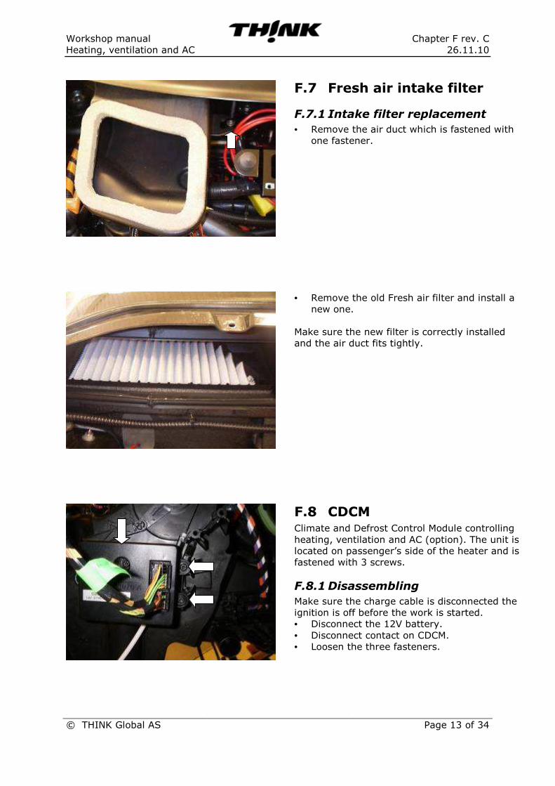
F.7 Fresh air intake filter
F.7.1 Intake filter replacement • Remove the air duct which is fastened with
one fastener.
• Remove the old Fresh air filter and install a
new one.
Make sure the new filter is correctly installed
and the air duct fits tightly.
F.8 CDCM Climate and Defrost Control Module controlling
heating, ventilation and AC (option). The unit is
located on passenger’s side of the heater and is
fastened with 3 screws.
F.8.1 Disassembling Make sure the charge cable is disconnected the
ignition is off before the work is started.
• Disconnect the 12V battery.
• Disconnect contact on CDCM.
• Loosen the three fasteners.

Workshop manual Chapter F rev. C
Heating, ventilation and AC 26.11.10
© THINK Global AS Page 14 of 34
F.8.2 Assembling Assemble in reverse order.
Tightening torque = 1,9 Nm
F.9 Heater
F.9.1 Disassembling of the control panel
Remove the radio and disconnect connectors
and antenna.
Remove the frame with indicator lights. The
frame is fastened with clips.
− Pull the frame in the middle below the
control panel loosening the two barbs at the
bottom.
− Pull the horizontal part of the frame below
the radio by loosening the fasteners
loosening the fasteners at both sides of the
radio.
− Pull the upper part of the frame to loosen
the upper fasteners.
Make sure the frame is pulled straight out.
Loosen the connector and pull it sideways
through the opening between the center vents
and the inner frame.

Workshop manual Chapter F rev. C
Heating, ventilation and AC 26.11.10
© THINK Global AS Page 15 of 34
Loosen the center panel.
This is fastened with two fasteners at the top
as shown in the picture.
Loosen two fasteners at the bottom; one on
each side of the center stack (one side shown
in the picture).
Pull both sides of the frame to loosen clips
along the edge.
The control panel with buttons for heating and
ventilation can either be taken out individually
or together with the frame.
The control panel is fastened to the frame with
2 screws. Loosen the fasteners, press the white
clips down and flip the panel outwards.

Workshop manual Chapter F rev. C
Heating, ventilation and AC 26.11.10
© THINK Global AS Page 16 of 34
The picture is showing the wire for heating and
ventilation connected to the back of the control
panel. Electrical contact is here already
disconnected.
To disconnect the wire pull the anchorage to
one side (1) releasing the wire from the slot.
Then pull the plate locking the knob (2) at the
end of the wire.
F.9.2 Assembling Assemble in reverse order.
F.9.3 Disassembling – tube Assembly
Intake tubes to the heater run from the motor
compartment to the heater on the driver’s side
of the car.
• Open the hood, squeeze the coolant hoses,
loosen the clamps and remove the hoses.
• Loosen metal plate and pull it off together
with the seal.
• Loosen fastener (1).
• Loosen fastener (2).
Place a collector or a towel below the tubes to
avoid coolant running into the interior.
• Push the tubes upwards/against the motor
compartment releasing them at the bottom.
The pipes can now be pull slightly to the side
and then down and out.
F.9.4 Assembling Assemble in reverse order.
1
2
1 2

Workshop manual Chapter F rev. C
Heating, ventilation and AC 26.11.10
© THINK Global AS Page 17 of 34
F.9.5 Disassembling– heater element
Before the heater element is removed the
tubes must be loosened (see section about).
• Loosen heater element fasteners.
• Pull the element out.
F.9.6 Assembling Assemble in reverse order.
Remember to connect the tubes afterwards.
F.9.7 Disassembling– blower To be able to replace the heater blower the
following must be removed:
• Indicator bar and the frame around the
control panel.
• Gear console cover and both closure
panels.
CAUTION! Be careful when removing the
closure panel not damaging the pins.
• Knee bolster and hood release handle.
• Striker in the motor compartment (1).
• Bracket around the pipes in the motor
compartment (2).
It is now possible to access the blower and
loosen it. It is also probably possible to wriggle
the blower down between the steering column
and the heater. To do this the heater must be
moved slightly to the right. If this is not
possible the complete dashboard must be
removed before the blower is removed.
• Loosen the contact. Pull it loose at the
bottom (1), rotate it around the axle at the
top (2) and lift the axle off.
• Lift the latch up and out (3) making it
possible to loosen the blower house.
• Remove the complete blower.
1
2
1
3
2
Workshop manual Chapter F rev. C
Heating, ventilation and AC 26.11.10
© THINK Global AS Page 18 of 34
F.9.8 Assembling Assemble in reverse order.
F.9.9 Disassembling – blower resistor
The blower resistor is located on the
passenger’s side of the heater.
• Push the sides of the connector (1) and pull
it out.
• Loosen the fastener (2).
• Pull the blower resistor out.
F.9.10 Assembling
Assemble in reverse order.
2
1

Workshop manual Chapter F rev. C
Heating, ventilation and AC 26.11.10
© THINK Global AS Page 19 of 34
F.9.11 Disassembling –
complete heater
To remove the complete heater Assembling the
dashboard must be removed. See separate
section in chapter H interior.
• Loosen air vents.
• Loosen contact.
• Loosen fasteners.
NOTE:
The following parts on the heater can be
replaced separately: Control panel, pipes,
Heater core, blower, blower resistor, harness
and the distributor case.
Note: AC equipped
Evaporator cannot be serviced separately. The
complete unit must be replaced

Workshop manual Chapter F rev. C
Heating, ventilation and AC 26.11.10
© THINK Global AS Page 20 of 34
F.9.12 Assembling
Assemble in reverse order.
Fill coolant if necessary and bleed the heating
circuit.
Tightening torque:
Heater to the dashboard = 7 Nm
F.10 AC Air - Conditioning system
The system supplies the cabin with mixed air
temperature. Condensed water will be drained
from the evaporator area during operation.
This is a normal condition.
F.10.1 Working on AC system
SAFETY WARNING!
It is necessary to wear suitable protection such
as goggles and gloves. Contact with the
refrigerant can cause blindness as well as other
injuries to the operator.
• Carefully read the instruction
• Do not open in case of rain or high humidity
• Use gloves
• Use protective goggles
• Refrigerant vapor in combination with
fire will cause toxic vapor. Don’t smoke
when working with AC

Workshop manual Chapter F rev. C
Heating, ventilation and AC 26.11.10
© THINK Global AS Page 21 of 34
Use an AC service unit with two connections,
for HP and LP (high pressure/low pressure)
F.10.2 Specifications
• Maximum allowed air temperature at center panel outlet: 5-10° C at 25°C ambient air temperature.
• Fuse
a) Condenser fan: 20A
b) Cabin / heater - fan: 25A
• Refrigerant capacity R134: 490g
• Oil content in compressor, evaporates, condenser and receiver dryer is not specified, replacement of
components weighed amount of oil in each component and replaced
• Total amount of oil 130CC
• Oil type POE (Ze-GLES RB68 synthetic oil) • Evacuation time recommended 20 min • Normal static pressure, 5bar (25 °C room temperature), see the separate table
• Max pressure HP 24bar and LP ca3 bar at max cooling • Pressure sensor on the HP side • Temperaturdifference in/out condenser 80/90°C

Workshop manual Chapter F rev. C
Heating, ventilation and AC 26.11.10
© THINK Global AS Page 22 of 34
F.10.3 Leak test (gas sniffer and
UV/transfluid)
By use of Sniffer:
It is not necessary to fill the AC system with UV
tracer before the test. The sniffer picks up traces
of R134a gas when the AC is active
Move the device along the components of the
facility to ascertain any possible leaks in the
system. Always follow the search device product
guide
By use of tracer fluid and UV light:
Alternatively, leakage searches using tracerfluid.
To ensure an optimal result, the car must be
driven for 3-5days with activated AC system.
F.10.4 Leak test by use of N2
Gas
This test is based on pressurize system with N2.
Step 1 Evacuate all R134a with an AC service
unit
Step 2 Pressurize the system in 3 steps up to
MAX 15 bar (evaporator may be damaged)
Often the leaks are easy to find at 3-5bar
Step 3 Listen for any leaks
Step 4 Use a soap/water solution and spray on
Components, hoses and connections. Leaks will
cause soap bubbles.

Workshop manual Chapter F rev. C
Heating, ventilation and AC 26.11.10
© THINK Global AS Page 23 of 34
F.10.5 AC system location
The refrigeration equipment
is located in the engine compartment
F.10.6 AC Static pressure test
AC compressor not active:
Open up valves (for proper handling of the AC
service unit, read the user guide)
Connect hoses to the service ports, high
pressure (HP red line) and low-pressure (LT
blue line).
Read the high pressure and low pressure
manometer. Meters should display the same
pressure value.
Pressure to conform to the following list
Ambient
temperature
Static pressure
+15 Celsius 3,9 bar
+20 Celsius 4,7bar
+25 Celsius 5,6bar
+30 Celsius 6,7bar
+35 Celsius 7,8bar
+40 Celsius 9,1bar
Condenser Pressure
Transduce Compressor
r Reciver drier
Expansion Valve TXV

Workshop manual Chapter F rev. C
Heating, ventilation and AC 26.11.10
© THINK Global AS Page 24 of 34
F.11 Draining the AC system
NOTE: For proper handling of the AC service
station, read the user guide
Connect to service hoses of high pressure (red
line) and low-pressure pipe (blue line).
Start the evacuating of the system. For correct
“vacuum” time se technical data.
Important:
Use correct time to ensure that all
incondensable (R134a) and moisture are
evacuated from the system.
Store the recovered R134a and oil for later
use.
Extracted oil must be replaced with new oil of
the same type see specifications.
Note!
If components have been replaced, oil must be
aggregated for each component and added to
the recovered oil during the filling process.
For total amount of oil in the system allowed,
see specifications.

Workshop manual Chapter F rev. C
Heating, ventilation and AC 26.11.10
© THINK Global AS Page 25 of 34
F.11.1 Refilling of the AC
system
Before refilling with R134a, the AC system
must have passed the leak test and evacuation
must be done.
Fill With right amount of gas. Use only
specified refrigerant.
NOTE: For proper handling of the AC service
station, read the user guide
Warning!
Do not overfill, it can harm the system and
cause spill to the nature.
Fill the right amount oil ref previous chapter.
F.11.2 Test of condenser
function
• Start the AC system run for at least 5
minutes
• Measure the different between in / out
temperature for the condenser
Consenser Out Consenser in
Out

Workshop manual Chapter F rev. C
Heating, ventilation and AC 26.11.10
© THINK Global AS Page 26 of 34
DANGER !
HP inlet very hot (70-100°C)
To confirm condenser performance outlet
temperature should be approximately 15 °C
colder than the inlet.
F.11.3 AC performance temperature test
• Close all doors and windows.
• Set the system to recirculation
• Set the temperature to the coldest level.
• Set fan to its second speed.
• Maximum allowed air temperature at
center panel outlet see specification
• Set the system in normal position (fresh
air) repeat the test
• Maximum allowed air temperature at
center panel outlet see specification
F.12 Condenser A/C removal
Recover the refrigerant from the refrigerant
system.
Disconnect fan module el. connector.

Workshop manual Chapter F rev. C
Heating, ventilation and AC 26.11.10
© THINK Global AS Page 27 of 34
Disconnect the supply connector from the A/C
compressor.
Remove the nut that secures the A/C
discharge line to the compressor
Inspect seals and tubes for damage.
Any kinks or sharp bends in the refrigerant
plumbing will reduce the capacity of the entire
air conditioning system.
If refrigerant oil has been drained from the A/C
compressor, the same amount of oil should be
added to the refrigerant system. (See
specifications for correct oil type.)

Workshop manual Chapter F rev. C
Heating, ventilation and AC 26.11.10
© THINK Global AS Page 28 of 34
Important: Install plugs in, or tape over the
opened refrigerant line fittings and compressor
ports.
Disconnect the A/C discharge line from the
condenser.
Replace rubber O-ring. Lubricate the rubber
O–ring with clean refrigerant oil before
installation.
Remove cable ties from the wiring harness.

Workshop manual Chapter F rev. C
Heating, ventilation and AC 26.11.10
© THINK Global AS Page 29 of 34
Remove the 4 attaching bolts on the mounting
bracket
Release the condenser support bracket.
Take care of rubber bushing when the support
bracket is removed.
Carefully lift the condenser up and hold it.

Workshop manual Chapter F rev. C
Heating, ventilation and AC 26.11.10
© THINK Global AS Page 30 of 34
Disconnect the discharge line from the
receiver/drier.
Carefully lift condenser up, and remove it from
the engine compartment.
NOTE: Inspect that the rubber bushings located
under the condenser are in correct location
after removal.
Important!
Use only refrigerant oil of the
type recommended for the compressor in the
vehicle
Add same amount off refrigerant oil that has
been removed from the refrigerant system.

Workshop manual Chapter F rev. C
Heating, ventilation and AC 26.11.10
© THINK Global AS Page 31 of 34
F.13 Assembling of the condenser
Install the condenser in reverse steps. Replace
the rubber O-ring. Lubricate the rubber O–ring
with clean refrigerant oil before installation
F.14 Expansion valve removal Recover the refrigerant from the refrigerant
system.
The front “H” valve-type thermal expansion
valve
(TXV) is located at the dash panel between the
liquid and suction lines, and the evaporator
coil.
Release wiring harness located over PCU.
Remove the bolt securing the refrigerant lines
to the expansion valve (TXV).

Workshop manual Chapter F rev. C
Heating, ventilation and AC 26.11.10
© THINK Global AS Page 32 of 34
Remove the bolt securing the expansion valve
to the evaporator
Carefully remove the expansion valve from the
evaporator.
Inspect rubber O-rings and tube flange for
damage.
F.15 Assembling of expansion valve
Install the expansion valve in reverse steps.
Replace rubber O-ring. Lubricate the rubber
O–ring with clean refrigerant oil before
installation.

Workshop manual Chapter F rev. C
Heating, ventilation and AC 26.11.10
© THINK Global AS Page 33 of 34
F.16 Replace A/C compressor
Recover the refrigerant from the refrigerant
system.
Disconnect the wiring harness connector at
compressor.
Remove the nut securing the suction line fitting
to the top of the compressor.
Disconnect the suction line fitting from the
compressor suction port.
Remove the seal from the suction line fitting
Disassemble the ground cable.

Workshop manual Chapter F rev. C
Heating, ventilation and AC 26.11.10
© THINK Global AS Page 34 of 34
Disassemble the compressor support bolts.
Carefully lift the compressor up, and remove it
from the engine compartment.
Drain the compressor for refrigerant oil and
measure the amount of oil. Add the same
amount of oil into the refrigerant system, when
installing the new compressor.

Workshop manual Chapter F rev. C
Heating, ventilation and AC 26.11.10
© THINK Global AS Page 35 of 34
F.17 Assembling of the compressor
Install the compressor in reverse steps.
Replace rubber O-ring. Lubricate the rubber
O–ring with clean refrigerant oil before
installation.
Related Documents