SOUTH DAKOTA DRAINAGE MANUAL October 2011 Chapter 9 ROADSIDE CHANNELS

Welcome message from author
This document is posted to help you gain knowledge. Please leave a comment to let me know what you think about it! Share it to your friends and learn new things together.
Transcript

SOUTH DAKOTA DRAINAGE MANUAL
October 2011
Chapter 9
ROADSIDE CHANNELS


South Dakota Drainage Manual Roadside Channels
9-i
Table of Contents
Section Page 9.1 INTRODUCTION ..........................................................................................9-1 9.2 OPEN-CHANNEL FLOW ..............................................................................9-3
9.2.1 General ...........................................................................................9-3 9.2.2 Definitions .......................................................................................9-3
9.2.2.1 Specific Energy ...............................................................9-3 9.2.2.2 Energy Gradeline ............................................................9-4 9.2.2.3 Steady and Unsteady Flow .............................................9-4 9.2.2.4 Uniform Flow and Non-Uniform Flow ..............................9-4 9.2.2.5 Gradually Varied and Rapidly Varied Flow ......................9-4 9.2.2.6 Froude Number ...............................................................9-4 9.2.2.7 Critical Flow ....................................................................9-5 9.2.2.8 Subcritical Flow ...............................................................9-5 9.2.2.9 Supercritical Flow ............................................................9-5 9.2.2.10 Hydraulic Jump ...............................................................9-6
9.2.3 Flow Classification ..........................................................................9-6 9.2.4 Equations ........................................................................................9-6
9.2.4.1 Continuity Equation .........................................................9-7 9.2.4.2 Manning’s Equation .........................................................9-7 9.2.4.3 Energy Equation .............................................................9-8
9.3 HYDRAULIC ANALYSIS ..............................................................................9-10
9.3.1 General ...........................................................................................9-10 9.3.2 Cross Sections ................................................................................9-10 9.3.3 Manning’s n Value Selection ...........................................................9-11 9.3.4 Single-Section Analysis ...................................................................9-11 9.3.5 Step-Backwater Analysis ................................................................9-12
9.4 DESIGN PRACTICES AND PROCEDURES................................................9-14
9.4.1 SDDOT Practices ............................................................................9-14
9.4.1.1 Design Methodology (Channel Linings) ..........................9-14 9.4.1.2 Channel Cross Sections ..................................................9-15 9.4.1.3 Channel Slope ................................................................9-15

South Dakota Drainage Manual Roadside Channels
9-ii
Table of Contents (Continued)
Section Page
9.4.1.4 Freeboard .......................................................................9-15 9.4.1.5 Channel Bends ...............................................................9-15 9.4.1.6 Channel Linings ..............................................................9-16
9.4.2 Step-by-Step Procedure ..................................................................9-18
9.5 EXAMPLE PROBLEMS ................................................................................9-27 9.6 REFERENCES .............................................................................................9-31

South Dakota Drainage Manual Roadside Channels
9-iii
List of Figures
Figure Page Figure 9.1-A SYMBOLS AND DEFINITIONS .......................................................... 9-2 Figure 9.2-A SPECIFIC ENERGY DIAGRAM .......................................................... 9-3 Figure 9.2-B TERMS IN THE ENERGY EQUATION ............................................... 9-9 Figure 9.3-A NOMOGRAPH FOR NORMAL DEPTH ............................................ 9-13 Figure 9.4-A CLASSIFICATION OF VEGETATION COVERS AS TO
DEGREES OF RETARDANCY ......................................................... 9-17 Figure 9.4-B SAMPLE ROADSIDE CHANNEL ...................................................... 9-19 Figure 9.4-C TYPICAL MANNING’S ROUGHNESS COEFFICIENTS (n) ............. 9-23 Figure 9.4-D MANNING’s n VERSUS RELATIVE ROUGHNESS FOR
SELECTED LINING TYPES (HEC 15, Reference (6))...................... 9-24 Figure 9.4-E MANNING’s n VERSUS HYDRAULIC RADIUS, R, FOR
CLASS B VEGETATION (HEC 15, Reference (6)) ........................... 9-25 Figure 9.4-F PERMISSIBLE SHEAR STRESSES (τp) FOR VARIOUS
PROTECTION MEASURES ............................................................. 9-26 Figure 9.5-A MAXIMUM DEPTH AND DISCHARGE FOR CLASS B
VEGETATION (In SDDOT Standard Channel with n = 0.035) .......... 9-28 Figure 9.5-B MAXIMUM DEPTH AND DISCHARGE FOR TRM ............................ 9-29

South Dakota Drainage Manual Roadside Channels
9-iv
South Dakota Drainage Manual Roadside Channels
9-1
Chapter 9 ROADSIDE CHANNELS
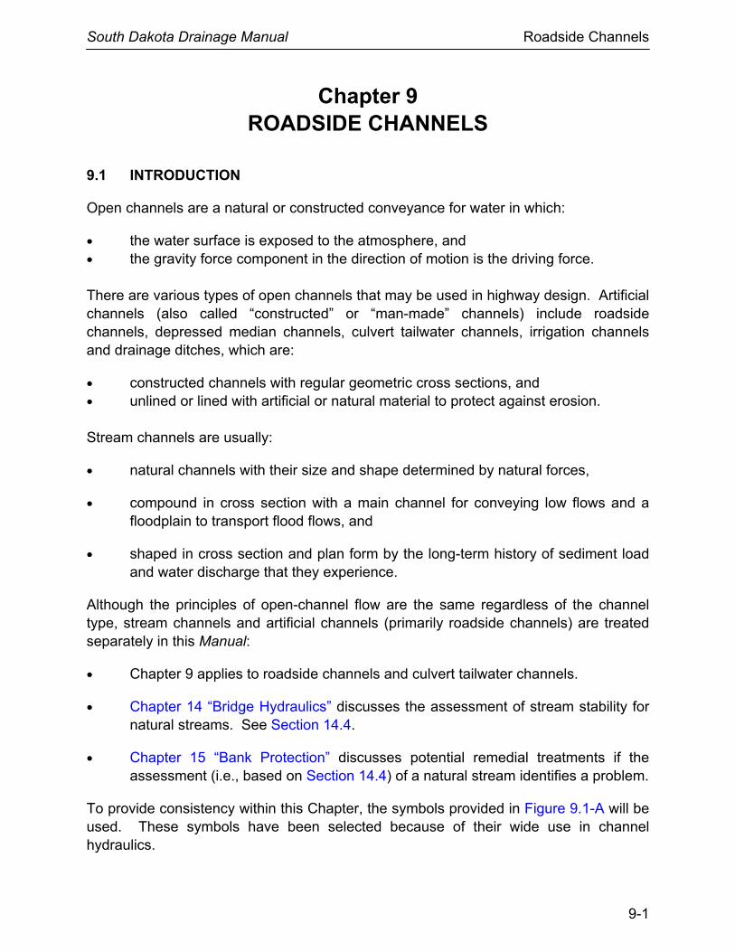
9.1 INTRODUCTION
Open channels are a natural or constructed conveyance for water in which:
• the water surface is exposed to the atmosphere, and • the gravity force component in the direction of motion is the driving force. There are various types of open channels that may be used in highway design. Artificial channels (also called “constructed” or “man-made” channels) include roadside channels, depressed median channels, culvert tailwater channels, irrigation channels and drainage ditches, which are:
• constructed channels with regular geometric cross sections, and • unlined or lined with artificial or natural material to protect against erosion. Stream channels are usually:
• natural channels with their size and shape determined by natural forces,
• compound in cross section with a main channel for conveying low flows and a floodplain to transport flood flows, and
• shaped in cross section and plan form by the long-term history of sediment load and water discharge that they experience.
Although the principles of open-channel flow are the same regardless of the channel type, stream channels and artificial channels (primarily roadside channels) are treated separately in this Manual:
• Chapter 9 applies to roadside channels and culvert tailwater channels.
• Chapter 14 “Bridge Hydraulics” discusses the assessment of stream stability for natural streams. See Section 14.4.
• Chapter 15 “Bank Protection” discusses potential remedial treatments if the assessment (i.e., based on Section 14.4) of a natural stream identifies a problem.
To provide consistency within this Chapter, the symbols provided in Figure 9.1-A will be used. These symbols have been selected because of their wide use in channel hydraulics.

South Dakota Drainage Manual Roadside Channels
9-2
Symbol Definition Units
A Cross sectional area sq ft
B Bottom width ft
d Hydraulic depth ft
dc Critical depth of flow ft
D50 Median diameter of riprap, or median grain size in
E Specific energy ft
Fr Froude number —
g Acceleration due to gravity ft/sec2
h Stage (water surface height) ft
hL Head loss ft
K Conveyance capacity cfs
ks Roughness height ft
L Channel reach length ft
n Manning’s roughness coefficient —
P Wetted perimeter ft
Q Discharge (flow rate) cfs
q Discharge per unit width cfs
R Hydraulic radius (A/P) ft
Rc Mean radius of the bend ft
S Energy gradeline slope or channel slope ft/ft
T Channel top width ft
V Velocity of flow fps
Vc Critical velocity fps
y Depth of flow ft
yc Critical depth ft
z Elevation head ft
z Horizontal distance ft
γ Unit weight of water pcf
τd Shear stress (tractive force) psf
τp Permissible shear stress psf
α Velocity distribution coefficient —
θ Channel slope angle degrees
Figure 9.1-A ⎯ SYMBOLS AND DEFINITIONS

South Dakota Drainage Manual Roadside Channels
9-3
9.2 OPEN-CHANNEL FLOW
9.2.1 General
The design analysis for all channels proceeds according to the basic principles of open-channel flow (see References (1), (2) and (3)). The basic principles of fluid mechanics ⎯ continuity, momentum and energy — can be applied to open-channel flow with the additional complication that the position of the free surface is usually one of the unknown variables. The determination of this unknown is one of the primary objectives of open-channel flow analysis. The following discussion is focused on the analysis of channels that are prismatic in shape. The regular shape can be an approximation so that a tailwater analysis can be simplified or an actual shape proposed for construction.
9.2.2 Definitions
9.2.2.1 Specific Energy
Specific energy, E, is defined as the energy head relative to the channel bottom. See Figure 9.2-A for a plot of the specific energy diagram. If the channel is not too steep (slope less than 10%) and the streamlines are nearly straight and parallel (so that the hydrostatic assumption holds), the specific energy becomes the sum of the depth and velocity head.
E = y + (V 2/2g) (Equation 9.1)
where:
y = depth, ft V = mean velocity, fps g = gravitational acceleration, 32.2 ft/sec2
Source: Adopted from HDS No. 4, Reference (2).
Figure 9.2-A ⎯ SPECIFIC ENERGY DIAGRAM

South Dakota Drainage Manual Roadside Channels
9-4
9.2.2.2 Energy Gradeline
The total head is the specific energy head plus the elevation of the channel bottom with respect to some datum. The line joining the total head from one cross section to the next defines the energy gradeline.
9.2.2.3 Steady and Unsteady Flow
A steady flow is one in which the discharge passing a given cross section is constant with respect to time. The maintenance of steady flow in any reach requires that the rates of inflow and outflow be constant and equal. When the discharge varies with time, the flow is unsteady.
9.2.2.4 Uniform Flow and Non-Uniform Flow
A non-uniform flow is one in which the velocity and depth vary in the direction of motion, while they remain constant in uniform flow. Uniform flow can only occur in a prismatic channel, which is a channel of constant cross section, roughness and slope in the flow direction; however, non-uniform flow can occur either in a prismatic channel or in a natural channel with variable properties.
9.2.2.5 Gradually Varied and Rapidly Varied Flow
A non-uniform flow in which the depth and velocity change gradually enough in the flow direction that vertical accelerations can be neglected is referred to as a gradually varied flow; otherwise, it is considered to be rapidly varied.
9.2.2.6 Froude Number
The Froude number, Fr, represents the ratio of inertial forces to gravitational forces, is an indicator of the type of flow, and is defined by:
( ) 5.0cosgd
VFrθ
= (Equation 9.2)
where:
V = mean velocity = Q/A, fps g = acceleration of gravity, 32.2 ft/sec2 d = hydraulic depth = A/T, ft A = cross-sectional area of flow, sq ft

South Dakota Drainage Manual Roadside Channels
9-5
T = channel top width at the water surface, ft Q = total discharge, cfs θ = channel slope angle, degrees This expression for the Froude number applies to any open channel or channel subsection with uniform or gradually varied flow. For rectangular channels, the hydraulic depth is equal to the flow depth.
9.2.2.7 Critical Flow
Critical flow occurs when the specific energy is a minimum for a given discharge in regular channel cross sections. The depth at which the specific energy is a minimum is called critical depth. At critical depth, the Froude number has a value of one. Critical depth is also the depth of maximum discharge when the specific energy is held constant. These relationships are illustrated in Figure 9.2-A. During critical flow, the velocity head is equal to half the hydraulic depth. The general expression for flow at critical depth is:
Q2/g = A3/T (Equation 9.3)
where:
Q = total discharge, cfs g = gravitational acceleration, 32.2 ft/sec2 A = cross-sectional area of flow, sq ft T = channel topwidth at the water surface, ft When flow is at critical depth, Equation 9.3 must be satisfied, no matter what the shape of the channel.
9.2.2.8 Subcritical Flow
Depths greater than critical depth occur in subcritical flow, and the Froude number is less than one. In this state of flow, small water surface disturbances can travel both upstream and downstream, and the control is always located downstream.
9.2.2.9 Supercritical Flow
Depths less than critical depth occur in supercritical flow, and the Froude number is greater than one. Small water surface disturbances are always swept downstream in supercritical flow, and the location of the flow control is always upstream.

South Dakota Drainage Manual Roadside Channels
9-6
9.2.2.10 Hydraulic Jump
A hydraulic jump occurs as an abrupt transition from supercritical to subcritical flow in the flow direction. There are significant changes in depth and velocity in the jump, and energy is dissipated. For this reason, the hydraulic jump is often employed to dissipate energy at highway drainage structures.
A hydraulic jump will not occur until the ratio of the flow depth (y1) in the approach channel to the flow depth (y2) in the downstream channel reaches a specific value that depends on the channel geometry. The depth before the jump is called the initial depth (y1), and the depth after the jump is the sequent depth (y2). When a hydraulic jump is used as an energy dissipator, controls to create sufficient tailwater depth are often necessary to control the location of the jump and to ensure that a jump will occur during the desired range of discharges. If the tailwater depth is lower than the sequent depth, a drop in the channel floor must be used to ensure a jump (see References (2) and (3)). Sills can be used to control a hydraulic jump if the tailwater depth is less than the sequent depth.
9.2.3 Flow Classification
The classification of open-channel flow can be summarized as follows:
Steady Flow
• Uniform Flow • Non-Uniform Flow
+ Gradually Varied Flow + Rapidly Varied Flow
Unsteady Flow
• Unsteady Uniform Flow (rare) • Unsteady Non-Uniform Flow
+ Gradually Varied Unsteady Flow + Rapidly Varied Unsteady Flow
The steady, uniform flow case and the steady, non-uniform flow case are the most fundamental types of flow treated in highway engineering hydraulics.
9.2.4 Equations
The following equations are those most commonly used to analyze open channel flow.

South Dakota Drainage Manual Roadside Channels
9-7
9.2.4.1 Continuity Equation
The continuity equation is the statement of conservation of mass in fluid mechanics. For the special case of one-dimensional, steady flow of an incompressible fluid, it assumes the simple form:
Q = A1V1 = A2V2 (Equation 9.4)
where:
Q = discharge, cfs
A = cross-sectional area of flow, sq ft
V = mean cross-sectional velocity, fps (which is perpendicular to the cross section)
The subscripts 1 and 2 refer to successive cross sections along the flow path.
9.2.4.2 Manning’s Equation
For a given depth of flow in an open channel with a steady, uniform flow, the mean velocity, V, can be computed with Manning’s equation:
V = (1.486/n)R 2/3S1/2 (Equation 9.5)
where:
V = velocity, fps
n = Manning’s roughness coefficient
R = hydraulic radius = A/P, ft
A = cross-sectional area of flow, sq ft
P = wetted perimeter, ft
S = slope of the energy gradeline, ft/ft (Note: For steady uniform flow, S = channel slope, ft/ft)
The selection of Manning’s n is generally based on observation; however, considerable experience is essential in selecting appropriate n values. See Section 9.3.3.

South Dakota Drainage Manual Roadside Channels
9-8
The continuity equation can be combined with Manning’s equation to obtain the steady, uniform flow discharge as:
Q = (1.486/n)AR2/3S1/2 (Equation 9.6)
For a given channel geometry, slope and roughness and a specified value of discharge Q; a unique value of depth occurs in steady, uniform flow. It is called normal depth and is computed from Equation 9.6 by expressing the area and hydraulic radius in terms of depth. The resulting equation may require a trial-and-error solution. If the normal depth is greater than critical depth, the slope is classified as a mild slope. If the normal depth is less than critical depth, the slope is classified as a steep slope. Thus, uniform flow is subcritical on a mild slope and supercritical on a steep slope.
9.2.4.3 Energy Equation
The energy equation expresses conservation of energy in open channel flow as energy per unit weight of fluid, which has dimensions of length and is therefore called energy head. The energy head is composed of potential energy head (elevation head), pressure head and kinetic energy head (velocity head). These energy heads are scalar quantities that give the total energy head at any cross section when added. Written between an upstream open-channel cross section designated 1 and a downstream cross section designated 2 (see Figure 9.2-B), the energy equation is:
( ) ( ) L222
211 hg2/Vhg2/Vh ++=+ (Equation 9.7)
where:
h1, h2 = the upstream and downstream stages, respectively, ft
V = mean velocity, fps
hL = head loss due to local cross-sectional changes (minor loss) and boundary resistance, ft
The stage, h, is the sum of the elevation head, z, at the channel bottom and the pressure head, which equals the depth of flow, y, for open-channel flow; i.e., h = z + y. The terms in the energy equation are illustrated graphically in Figure 9.2-B. The energy equation states that the total energy head at an upstream cross section is equal to the energy head at a downstream section plus the intervening energy head loss. The energy equation can only be applied between two cross sections at which the streamlines are nearly straight and parallel so that vertical accelerations can be neglected.

South Dakota Drainage Manual Roadside Channels
9-9
Source: HDS No. 4, Reference (2).
Figure 9.2-B ⎯ TERMS IN THE ENERGY EQUATION
South Dakota Drainage Manual Roadside Channels
9-10
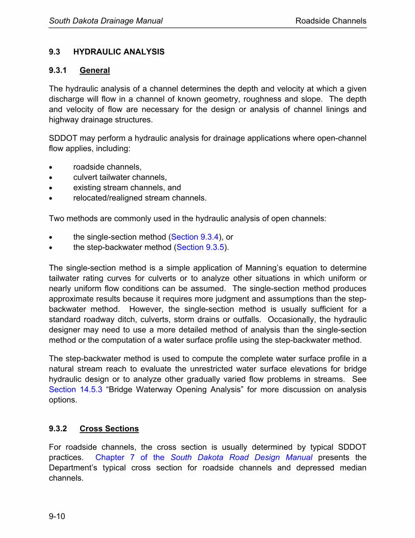
9.3 HYDRAULIC ANALYSIS
9.3.1 General
The hydraulic analysis of a channel determines the depth and velocity at which a given discharge will flow in a channel of known geometry, roughness and slope. The depth and velocity of flow are necessary for the design or analysis of channel linings and highway drainage structures.
SDDOT may perform a hydraulic analysis for drainage applications where open-channel flow applies, including:
• roadside channels, • culvert tailwater channels, • existing stream channels, and • relocated/realigned stream channels. Two methods are commonly used in the hydraulic analysis of open channels:
• the single-section method (Section 9.3.4), or • the step-backwater method (Section 9.3.5). The single-section method is a simple application of Manning’s equation to determine tailwater rating curves for culverts or to analyze other situations in which uniform or nearly uniform flow conditions can be assumed. The single-section method produces approximate results because it requires more judgment and assumptions than the step-backwater method. However, the single-section method is usually sufficient for a standard roadway ditch, culverts, storm drains or outfalls. Occasionally, the hydraulic designer may need to use a more detailed method of analysis than the single-section method or the computation of a water surface profile using the step-backwater method.
The step-backwater method is used to compute the complete water surface profile in a natural stream reach to evaluate the unrestricted water surface elevations for bridge hydraulic design or to analyze other gradually varied flow problems in streams. See Section 14.5.3 “Bridge Waterway Opening Analysis” for more discussion on analysis options.
9.3.2 Cross Sections
For roadside channels, the cross section is usually determined by typical SDDOT practices. Chapter 7 of the South Dakota Road Design Manual presents the Department’s typical cross section for roadside channels and depressed median channels.

South Dakota Drainage Manual Roadside Channels
9-11
Cross-sectional geometry of streams is defined by coordinates of lateral distance and ground elevation that locate individual ground points. The cross section is taken normal to the flow direction along a single, straight line where practical. Cross sections should be located to be representative of the subreach.
9.3.3 Manning’s n Value Selection
Manning’s n, the roughness coefficient, is affected by many factors, and its selection in natural channels depends heavily on engineering experience. Pictures of channels and floodplains for which the discharge has been measured and for which Manning’s n has been calculated are very useful (see References (3), (4) and (5)) for estimating n values for tailwater channels. See Figure 9.4-C for n-values used for channel linings.
9.3.4 Single-Section Analysis
The single-section analysis method (slope-area method) is a solution of Manning’s equation for the normal depth of flow given the discharge and cross section properties including geometry, slope and roughness. It implicitly assumes the existence of steady, uniform flow; however, uniform flow rarely exists in either artificial or natural stream channels. Nevertheless, the single-section method is often used to design roadside channels assuming uniform flow and to develop a stage-discharge rating curve in a stream channel to be used for tailwater at a culvert or storm drain outlet.
A stage-discharge curve is a graphical relationship of streamflow depth or elevation to discharge at a specific point in a channel. This relationship should cover a range of discharges up to at least the base (100-year) flood or check flood. The stage-discharge curve can be determined as follows:
• Select the typical cross section at or near the location where the stage-discharge curve is needed.
• Subdivide the cross section and assign n-values to subsections as described in Section 9.3.3.
• Estimate water-surface slope. Because uniform flow is assumed, the average slope of the channel can usually be used.
• Apply a range of incremental water surface elevations to the cross section.
• Calculate the discharge using Manning’s equation for each incremental elevation. Total discharge at each elevation is the sum of the discharges from each subsection at that elevation. In determining hydraulic radius, the wetted perimeter should be measured only along the solid boundary of the cross section and not along the vertical water interface between subsections.

South Dakota Drainage Manual Roadside Channels
9-12
• After the discharge has been calculated at several incremental elevations, a plot of stage versus discharge should be made. This plot is the stage-discharge curve, and it can be used to determine the water surface elevation corresponding to the design discharge or other discharge of interest.
Although the above procedure can be accomplished manually, software (see Chapter 18 “Hydraulic Software”) or design aids (e.g., see Figure 9.3-A) are used for trapezoidal and prismatic channels.
9.3.5 Step-Backwater Analysis
Step-backwater analysis is recommended for determining unrestricted water surface profiles for roadside channels that are long, large or costly. Because the calculations involved in this analysis are tedious and repetitive, it is recommended that the hydraulic designer use software such as HEC-RAS (see Chapter 18 “Hydraulic Software”). This software can be used for calculating water surface profiles for steady, gradually varied flow in a natural or constructed channel. Both subcritical and supercritical flow profiles can be calculated.

South Dakota Drainage Manual Roadside Channels
9-13
Source: HEC 15, Reference (6).
Figure 9.3-A ⎯ NOMOGRAPH FOR NORMAL DEPTH

South Dakota Drainage Manual Roadside Channels
9-14
9.4 DESIGN PRACTICES AND PROCEDURES
This Section presents typical SDDOT hydraulic practices for roadside channels and outlines a hydraulic design procedure. The alignment, cross section and grade of roadside channels is usually influenced by the geometric and roadside safety design applicable to the project.
The primary function of roadside channels is to collect surface runoff from the highway and areas that drain to the right-of-way and convey the accumulated runoff to acceptable outlet points. A secondary function of a roadside channel is to drain subsurface water from the base of the roadway to prevent saturation and loss of support for the pavement or to provide a positive outlet for subsurface drainage systems such as pipe underdrains and edge drains.
9.4.1 SDDOT Practices
9.4.1.1 Design Methodology (Channel Linings)
SDDOT uses the 1988 version of HEC 15 (Reference (6)) as its basic reference to select and design linings for its roadside channels. See Chapter 18 “Hydraulic Software.” The designer should note that the riprap design procedures in HEC 15 are for constructed channels that have a uniform cross section. The flow in the channel should be either steady, uniform flow or gradually varied. The 2005 version of HEC 15 (Reference (7)) may be used as an alternative if a more rigorous analysis is desired.
The HEC 15 design methodology for the evaluation of channel linings is based on shear stress. Shear stress is the tractive force caused by water flowing in the channel. A channel is unstable where the flow-induced shear stress exceeds the permissible shear stress of the channel liner material. Hydraulic conditions in a drainage channel can become erosive even at fairly mild highway grades. As a result, these channels often require stabilization against erosion.
The Office of Road Design has developed spreadsheets to compute the normal water depth, shear stress and water velocity at the required locations for the SDDOT 20-ft standard roadside ditch, flat-bottom ditch or V-ditch.
Shear stress is normally analyzed for a 10-year flood event, and the discharges should be computed using the same methods required for culvert design, which varies based on drainage area size. The designer should provide these spreadsheets or similar information to the Erosion Control Designer prior to scheduling a final design inspection to consider installing permanent erosion control measures.

South Dakota Drainage Manual Roadside Channels
9-15
9.4.1.2 Channel Cross Sections
Chapter 7 of the South Dakota Road Design Manual presents the Department’s typical cross section for roadside channels and depressed median channels.
9.4.1.3 Channel Slope
The channel bottom longitudinal slope is generally dictated by the adjacent roadway profile and, therefore, is usually fixed. If channel stability conditions warrant and available linings are not sufficient, it may be feasible to reduce the channel gradient slightly relative to the roadway profile. For channels outside the highway right-of-way, the slope may also be adjusted slightly.
Channel slope is one of the major parameters in determining shear stress. For a given design discharge, the shear stress in the channel with a subcritical slope is smaller than one with a supercritical slope. Roadside channels with gradients in excess of approximately 2% will flow in a supercritical state. Most flexible lining materials are suitable for protecting channel gradients up to 10%. Riprap and wire-enclosed riprap are suitable for protecting steep channels with gradients exceeding 10%.
Flat or nearly flat slopes should be avoided. If it is not possible to maintain a 0.5% grade, a paved section may be used with an absolute minimum of a 0.2% grade.
9.4.1.4 Freeboard
The freeboard of a channel is the vertical distance from the water surface to the top of the channel at design condition. The importance of this factor depends on the consequence of overflow of the channel bank. At a minimum, the freeboard should be sufficient to prevent waves or fluctuations in water surface from overflowing sides. In a permanent roadway channel, approximately 6 in of freeboard over the design depth should be adequate. For temporary channels, freeboard is not necessary. Steep-gradient channels ( > 10%) should have a freeboard height equal to the flow depth. This allows for large variations to occur in flow depth for steep channels caused by waves, splashing and surging. Lining materials should extend to the freeboard elevation. The designer should provide the elevation limits to the Erosion Control Designer at the critical locations.
9.4.1.5 Channel Bends
Flow around a bend in an open channel induces centrifugal forces because of the change in flow direction. This results in a superelevation of the water surface. The water surface is higher at the outside of the bend than at the inside of the bend. This superelevation can be estimated by the equation:

South Dakota Drainage Manual Roadside Channels
9-16
c
2
gR
TVd =Δ = superelevation of the water surface (Equation 9.8)
where:
V = mean velocity, fps T = surface width of the channel, ft g = gravitational acceleration, 32.2 ft/sec2
Rc = mean radius of the bend, ft
9.4.1.6 Channel Linings
Designers should analyze drainage locations throughout the project with potential erosion problems to evaluate the suitability and stability of the channel lining. Examples of locations to consider are:
• existing erosion areas, • ditches with grades steeper than 4%, • drainage areas greater than 10 acres, • roadway embankments that transition from a ditch cut to a fill, • toe of fills that result in a V-ditch, and • narrow channel sections (steep-sided V-ditches). In addition, the designer should consider that occasionally even small concentrated flows in a channel may merit evaluation, depending on the channel grade and configuration.
The following identifies SDDOT typical practices for the selection of a channel lining type:
1. Temporary Linings: • Crimped straw (mulch) • Erosion control blanket • Wood fiber mulch • Bonded fiber matrix
2. Permanent Linings (in order of preference):
• Vegetation (Retardance Class B); see Figure 9.4-A • Turf reinforcement mats • Riprap • Gabions • Concrete liner

South Dakota Drainage Manual Roadside Channels
9-17
Retardance Cover Condition
A Weeping lovegrass Yellow bluestem Ischaemum
Excellent stand, tall (average 30 in) Excellent stand, tall (average 36 in)
B
Kudzu Bermuda grass Native grass mixture: little bluestem, bluestem, blue
gamma, other short- and long-stem Midwest grasses
Weeping lovegrass Lasperdeza sericea Alfalfa Weeping lovegrass Kudzu Blue gamma
Very dense growth, uncutGood stand, tall (average 12 in) Good stand, unmowed Good stand, tall (average 24 in) Good stand, not woody, tall (average 19 in) Good stand, uncut (average 11 in) Good stand, unmowed (average 13 in) Dense growth, uncut Good stand, uncut (average 13 in)
C
Crabgrass Bermuda grass Common lesperdeza Grass-legume mixture: summer (orchard grass
redtop, Italian ryegrass and common lespedeza)
Centipedegrass Kentucky bluegrass
Fair stand, uncut (10 in − 48 in) Good stand, mowed (average 6 in) Good stand, uncut (average 11 in) Good stand, uncut (6 in − 8 in) Very dense cover (average 6 in) Good stand, headed (6 in −12 in)
D
Bermuda grass Common lespedeza Buffalo grass Grass-legume mixture: fall, spring (orchard grass
redtop, Italian ryegrass and common lesperdeza)
Lespedeza sericea
Good stand, cut to 2½ inExcellent stand, uncut (average 4½ in) Good stand, uncut (3 in − 6 in) Good stand, uncut (4 in − 5 in) After cutting to 2 in (very good before cutting)
E Bermuda grass Bermuda grass
Good stand, cut to 1½ inBurned stubble
Notes: 1. Covers classified have been tested in experimental channel. Covers were green and generally uniform. Source
of table is HEC 15 (Reference (6)). 2. Most of the grasses in the Figure are not allowed by SDDOT seed mixtures. The typical vegetative grasses used
in South Dakota highway ditches have a Retardance Class of B.
Figure 9.4-A ⎯ CLASSIFICATION OF VEGETATION COVERS AS TO DEGREES OF RETARDANCY

South Dakota Drainage Manual Roadside Channels
9-18
3. Special Linings. These include composite linings that have a low-flow channel with one type of lining and upper side slopes with a different lining.
9.4.2 Step-by-Step Procedure
Each project is unique, but the following six basic design steps are normally applicable to the hydraulic design of roadside channels. Section 9.5 presents two examples to illustrate the hydraulic design procedure. To obtain the optimum roadside channel system design, it may be necessary to make several trials with various linings before a final design is achieved:
Step 1 Establish a Roadside Plan
A. Collect available site data. See Chapter 5 “Data Collection.” B. Document the existing and proposed plan-profile layout including
highway, culverts and bridges. C. Plot the locations of natural basin divides and roadside channel outlets.
Figure 9.4-B presents an example of a roadside channel plan/profile. D. Lay out the proposed roadside channels to minimize diversion flow
lengths.
Step 2 Establish Cross Section Data
A. Identify features that may restrict the cross section design:
• right-of-way limits, • trees or environmentally sensitive areas, • utilities, and/or • existing drainage facilities.
B. Provide a channel depth adequate to drain the subbase and minimize freeze-thaw effects.
C. Choose channel side slopes based on the SDDOT design criteria, including the consideration of safety, economics, soils, aesthetics and access. See Section 9.4.1.2.

South Dakota Drainage Manual Roadside Channels
9-19
Figure 9.4-B ⎯ SAMPLE ROADSIDE CHANNEL

South Dakota Drainage Manual Roadside Channels
9-20
Step 3 Determine Channel Grade
A. Plot initial longitudinal grades on plan-profile layout, including inlet and outlet considerations. See Section 9.4.1.3 for SDDOT practices.
B. Consider the influence of grade on type of lining. See Step 5.
C. Where practical, avoid features that may influence or restrict grade (e.g., utility locations).
D. Select final channel grade to minimize ponding and sediment accumulation.
Step 4 Check Flow Capacities and Adjust as Necessary
A. Compute the design discharge at the downstream end of a channel segment (see Chapter 7 “Hydrology”).
B. Set preliminary values of channel size, roughness coefficient and slope.
C. Determine maximum allowable depth of channel including freeboard. See Section 9.4.1.4 for SDDOT practices.
D. Check flow capacity using Manning’s equation and single-section analysis. For n values for the trial lining, refer to:
• Figure 9.4-C or 9.4-D for rigid, unlined, temporary, gravel and rock riprap linings, or
• Figure 9.4-E for grass linings
The hydraulic designer may select an alternative n value with proper documentation. For example, SDDOT practice is to limit the n value for the permanent grass lining to 0.035.
E. If capacity is inadequate, possible adjustments are as follows:
• increase bottom width,
• make channel side slopes flatter,
• make channel slope steeper,
• provide smoother channel lining, and/or
• install drop inlets and a parallel storm drain pipe beneath the channel to supplement channel capacity.

South Dakota Drainage Manual Roadside Channels
9-21
F. Provide smooth transitions at changes in channel cross section.
G. Provide extra channel storage where needed to replace floodplain storage and/or to reduce peak discharge.
Step 5 Determine Channel Lining/Protection Needed Note: The following procedure is based on HEC 15 (1988), Reference (6). See
Section 9.4.1.1 for more discussion on the use of the 1988 and 2005 versions of HEC 15.
A. Select a lining and determine the permissible shear stress τp in psf
from Figure 9.4-F. See Section 9.4.1.6 for typical SDDOT practices on selecting channel linings.
B. Estimate the flow depth and choose an initial Manning’s n from:
• Figure 9.4-C or 9.4-D for rigid, unlined, temporary, gravel and rock riprap linings; or
• Figure 9.4-E for Class B grass linings; or
• HEC 15 (1988) (Reference (6)) for Classes A, C, D and E grass linings.
The hydraulic designer may select an alternative n value with proper documentation. For example, SDDOT practice is to limit the n value for the permanent grass lining to 0.035.
C. Calculate normal flow depth, yn (ft), at design discharge using Manning’s equation and compare with the estimated depth. If they do not agree, repeat Steps 5B and 5C.
D. Compute maximum shear stress at normal depth as:
τd (psf) = 62.4ynS, where S = channel slope, ft/ft
E. If τd < τp, then lining is acceptable. Otherwise consider the following options:
• choose a more resistant lining; • decrease channel slope; • decrease slope in combination with drop structures; and/or • increase channel width and/or flatten side slopes.

South Dakota Drainage Manual Roadside Channels
9-22
Step 6 Analyze Outlet Points and Downstream Effects
A. Identify any adverse impacts (e.g., increased flooding or erosion to downstream properties) that may result from one of the following at the channel outlet:
• increase or decrease in discharge, • increase in velocity of flow, • concentration of sheet flow, • change in outlet water quality, or • diversion of flow from another watershed.
B. Mitigate any adverse impacts identified in Step 6A. Possibilities
include:
• increase capacity and/or improve lining of downstream channel;
• install velocity-control structures (e.g., energy dissipators; see Chapter 11);
• install sedimentation/infiltration basins or control structures to provide detention of increased runoff and/or sediment (see Chapter 13 “Storage Facilities”); and/or
• install weirs or other outlet devices to redistribute concentrated channel flow; see HEC 22 (Reference (9)).

South Dakota Drainage Manual Roadside Channels
9-23
Lining Category Lining Type
ks
(ft)
n-value1
Depth Ranges
0 – 0.5 ft 0.5 – 2.0 ft > 2.0 ft
Rigid
Concrete Asphalt Grouted Riprap Stone Masonry Soil Cement
0.015 0.018 0.040 0.042 0.025
0.013 0.016 0.030 0.032 0.022
0.013 0.016 0.028 0.030 0.020
Unlined Bare Soil Rock Cut
0.023 0.045
0.020 0.035
0.020 0.025
Temporary2 Straw with Net3
Curled Wood Mat4
Synthetic Mat5
0.121 0.112 0.066
0.065 0.066 0.036
0.033 0.035 0.025
0.025 0.028 0.021
Gravel6 1 in D50 2 in D50
0.082 0.164
0.044 0.066
0.033 0.041
0.030 0.034
Rock Riprap6 6 in D50 12 in D50
(Class A) 0.5 1.0
0.104 ⎯
0.069 0.078
0.035 0.040
1 n-values are representative of the depth ranges (i.e., n varies with the flow depth)
2 Some “temporary” linings become permanent when buried 3 Use for SDDOT Crimped Straw (Mulch) 4 Use for SDDOT Wood Fiber Mulch
5 Use for SDDOT Bonded Fiber Matrix 6 ks = D50 for gravel and rock riprap
Source: 1988 version of HEC 15 (Reference (6)).
Lining Category Lining Type
n-value1
Maximum Typical Minimum
Rolled Erosion Control Products (RECP)
Open-Weave Textile 0.028 0.025 0.022
Erosion Control Blankets 0.045 0.035 0.028
Turf Reinforcement Mat 0.036 0.030 0.024
Gabions Wire-Enclosed Rock Function of Rock Size
1 Typical n-value should be used for design. Actual n-value is a function of shear stress on the lining and coefficients based on all three manufacturer-supplied values. See HEC 15 (2005), Chapter 5 for RECP procedure and Chapter 7 for gabion procedure.
Source: 2005 version of HEC 15 (Reference (7)).
Figure 9.4-C ⎯ TYPICAL MANNING’S ROUGHNESS COEFFICIENTS (n)

South Dakota Drainage Manual Roadside Channels
9-24
Figure 9.4-D ⎯ MANNING’s n VERSUS RELATIVE ROUGHNESS FOR SELECTED LINING TYPES (HEC 15, Reference (6))

South Dakota Drainage Manual Roadside Channels
9-25
Figure 9.4-E ⎯ MANNING’s n VERSUS HYDRAULIC RADIUS, R, FOR CLASS B VEGETATION (HEC 15, Reference (6))

South Dakota Drainage Manual Roadside Channels
9-26
SDDOT Typical Linings τp (psf)
Class B Vegetation 2.10
Synthetic Mats (temporary linings) 2.00
Turf Reinforcement Mat 4.00
Rock Riprap
D50 = 6 in 2.50
D50 = 12 in (Class A Riprap) 5.00
6-in to 18-in Gabions 4.00*
Special Linings
Class A Vegetation 3.70
Class C Vegetation 1.00
Class D Vegetation 0.60
Class E Vegetation 0.35
Jute Net 0.45
Straw with Net 1.45
Curved Wood Mat 1.55
Gravel
D50 = 1 in 0.40
D50 = 2 in 0.80
4-in Geoweb 10.00
Concrete Construction Blocks (granular filter underlayer) > 20.00
Wedge-Shaped Blocks (with drainage slot) > 25.00
Soil Cement (8% cement) > 45.00
* This value is consistent with the Equation in Section 15.8.
Source: Reference (8).
Figure 9.4-F ⎯ PERMISSIBLE SHEAR STRESSES (τp) FOR VARIOUS PROTECTION MEASURES

South Dakota Drainage Manual Roadside Channels
9-27
9.5 EXAMPLE PROBLEMS
Example 9.5-1
Given: The SDDOT standard ditch section shown below is lined with a good stand (unmowed) of native grass mixture. The ditch gradient is 0.010 ft/ft.
Find: Compute the maximum discharge for which this lining will be stable and the corresponding flow depth.
Solution: From Figure 9.4-A, Native Grass Mixture is a retardance class of B and, from Figure 9.4-F, the permissible shear stress is:
τp = 2.1 psf
The allowable depth can be determined by assuming τp = τd:
y = τp /(62.4S) = 2.1/((62.4)(0.01)) = 3.36 ft
Determine the flow area (A) and hydraulic radius (R) for z1 = 4 and z2 = 5:
Atriangle = 5 sq ft for the first 0.5 ft Atrap. = y(b + z1y/2 + z2y/2) = 2.86 (20 + 2(2.86) + 2.5(2.86)) = 94 sq ft Atotal = 99 sq ft P = b + y(1 + z1
2)1/2 + y(1 + z22)1/2
P = 20 + 2.86 (1 + 16)1/2 + 2.86 (1 + 25)1/2 = 20 + 11.8 + 14.6 = 46.4 ft R = A/P = 99/46.4 = 2.13 ft The Manning’s n value from Figure 9.4-E is 0.075.
Solving for Q from Manning’s equation:
Q = (1.486/n)AR2/3S1/2 Q = (1.486/0.075)(99)(2.13)2/3 (0.01)1/2 = 325 cfs

South Dakota Drainage Manual Roadside Channels
9-28
Because this is a large channel and a deep depth of flow, SDDOT practice is to use an n = 0.035. Substituting this n, the channel has the following capacity:
Q = (1.486/0.035)(99)(2.13)2/3 (0.01)1/2 = 696 cfs
Note: This method is called the maximum discharge method and is useful for determining the stable channel capacity for a variety of different linings for comparison.
As a check, the FHWA Hydraulic Toolbox (Channel Calculator) (see Section 18.2.2) yields 325 cfs and 697 cfs respectively when the following cross section is entered:
The results can also be produced using the above cross section in HY-8; see Chapter 18 “Hydraulic Software.”
The FHWA Hydraulic Toolbox (Channel Calculator) was used to produce the data in Figure 9.5-A.
Slope (S) (ft/ft)
Maximum Depth (2.1/62.4S) (ft)
Maximum Q (cfs)
0.01 3.36 696
0.02 1.68 227
0.04 0.84 69
0.06 0.56 29
0.08 0.42 15
0.10 0.34 10
Figure 9.5-A ⎯ MAXIMUM DEPTH AND DISCHARGE FOR CLASS B VEGETATION (In SDDOT Standard Channel with n = 0.035)
Station Elevation
0 4
14 0.5
24 0
34 0.5
51.5 4

South Dakota Drainage Manual Roadside Channels
9-29
Example 9.5-2
Given: The SDDOT standard ditch section (shown below) will be used. The ditch gradient is 0.01 ft/ft. This is the same as Example 9.5-1, which established that Native Grass Mixture was acceptable for the permanent lining.
Find: Determine if the Turf Reinforcement Mat (TRM) is needed, either as a
temporary or permanent lining.
Solution: The solution follows the procedure outlined in Section 9.4.2 (Step 5), which is based on the tractive force method:
(1) Determine the permissible shear stress for TRM:
τp = 4.0 psf (Figure 9.4-F)
(2) Determine n = 0.03 from Figure 9.4-C.
(3) Calculate y using Manning’s equation (similar to Example 9.5-1). The FHWA Hydraulic Toolbox (Channel Calculator) was used to produce Figure 9.5-B.
Slope (S) (ft/ft)
Maximum Depth (4/62.4S) (ft)
Maximum Q (cfs)
0.01 > 4 NA
0.02 3.21 1043
0.04 1.60 337
0.06 1.07 172
0.08 0.80 101
0.10 0.64 64
Figure 9.5-B ⎯ MAXIMUM DEPTH AND DISCHARGE FOR TRM (In SDDOT Standard Channel with n = 0.03)

South Dakota Drainage Manual Roadside Channels
9-30
The TRM is not needed as a permanent lining on gradients less than 0.02 ft/ft if the design discharge is less than that shown in Figure 9.5-B. The TRM will provide temporary protection until grass is established and will provide for a stronger permanent lining. At slopes greater than 0.02 ft/ft, TRM substantially increases capacity of the channel as a permanent lining.

South Dakota Drainage Manual Roadside Channels
9-31
9.6 REFERENCES
(1) AASHTO, Highway Drainage Guidelines (4th Edition), Chapter 6, “Hydraulic Analysis and Design of Open Channels,” AASHTO Technical Committee on Hydrology and Hydraulics, 2005.
(2) Federal Highway Administration, Introduction to Highway Hydraulics, Hydraulic Design Series No. 4 (HDS 4), FHWA-NHI-08-090, Washington, DC, August 2008.
(3) Chow, V.T., Open Channel Hydraulics, McGraw-Hill, 1970, 1959.
(4) Arcement, G.J., Jr., and Schneider, V.R., Guide for Selecting Manning’s Roughness Coefficients for Natural Channels and Flood Plains, FHWA-TS-84-204, Federal Highway Administration, 1984.
(5) Barnes, H.H., Jr., “Roughness Characteristics of Natural Channels,” USGS Water Supply Paper 1849, US Government Printing Office, Washington, DC, 1978.
(6) Federal Highway Administration, Design of Roadside Channels with Flexible Linings, Hydraulic Engineering Circular No. 15 (HEC 15), FHWA-IP-87-7, Washington, DC, April 1988.
(7) Federal Highway Administration, Design of Roadside Channels with Flexible Linings, Hydraulic Engineering Circular No. 15 (HEC 15), Third Edition, FHWA-NHI-05-114, September 2005.
(8) Federal Highway Administration, Hydraulic Stability of Articulated Concrete Block Revetment Systems during Overtopping Flow, FHWA-RD-89-199, November 1989.
(9) Federal Highway Administration, Urban Drainage Design Manual Second Edition, Hydraulic Engineering Circular No. 22 (HEC 22), FHWA-NHI-10-009, 2009.

South Dakota Drainage Manual Roadside Channels
9-32
Related Documents