Chapter 9: Chapter 9: Logical Database Logical Database Design Design and the Relational and the Relational Model Model (ERD Mapping) (ERD Mapping)

Chapter 9: Logical Database Design and the Relational Model (ERD Mapping)
Jan 04, 2016
Welcome message from author
This document is posted to help you gain knowledge. Please leave a comment to let me know what you think about it! Share it to your friends and learn new things together.
Transcript
Chapter 9:Chapter 9:Logical Database Design Logical Database Design and the Relational Modeland the Relational Model
(ERD Mapping)(ERD Mapping)
Transforming EER Diagrams Transforming EER Diagrams into Relationsinto Relations
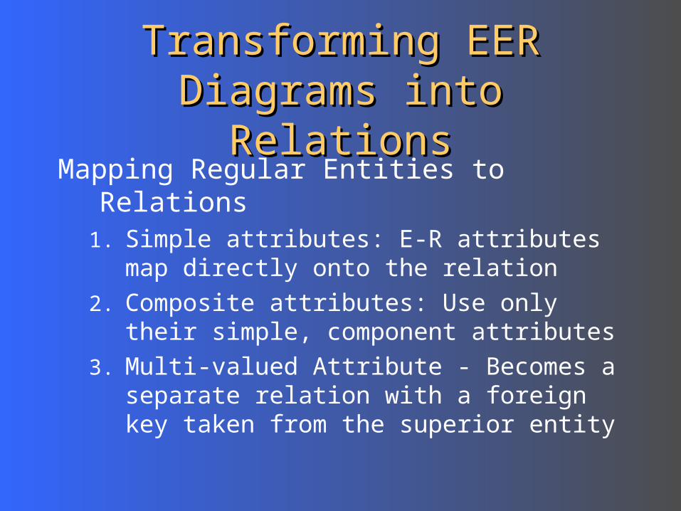
Mapping Regular Entities to Relations 1. Simple attributes: E-R attributes map directly
onto the relation
2. Composite attributes: Use only their simple, component attributes
3. Multi-valued Attribute - Becomes a separate relation with a foreign key taken from the superior entity
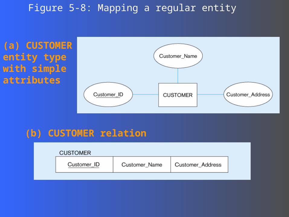
(a) CUSTOMER entity type with simple attributes
Figure 5-8: Mapping a regular entity
(b) CUSTOMER relation
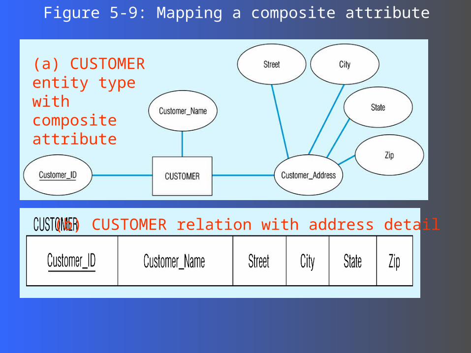
(a) CUSTOMER entity type with composite attribute
Figure 5-9: Mapping a composite attribute
(b) CUSTOMER relation with address detail
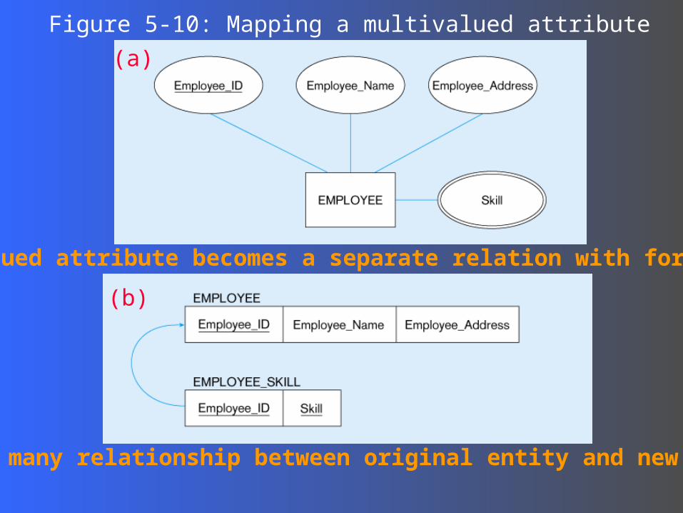
Figure 5-10: Mapping a multivalued attribute
1 – to – many relationship between original entity and new relation
(a)
Multivalued attribute becomes a separate relation with foreign key
(b)
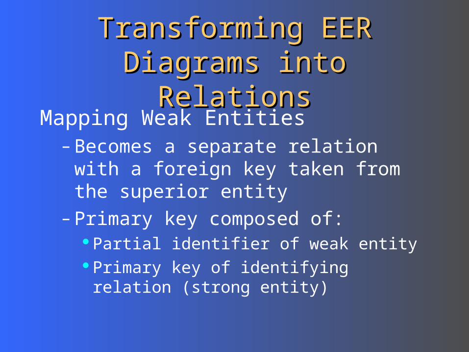
Transforming EER Diagrams Transforming EER Diagrams into Relationsinto Relations
Mapping Weak Entities– Becomes a separate relation with a
foreign key taken from the superior entity– Primary key composed of:
Partial identifier of weak entityPrimary key of identifying relation (strong
entity)
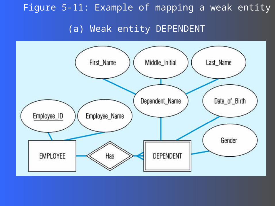
Figure 5-11: Example of mapping a weak entity
(a) Weak entity DEPENDENT
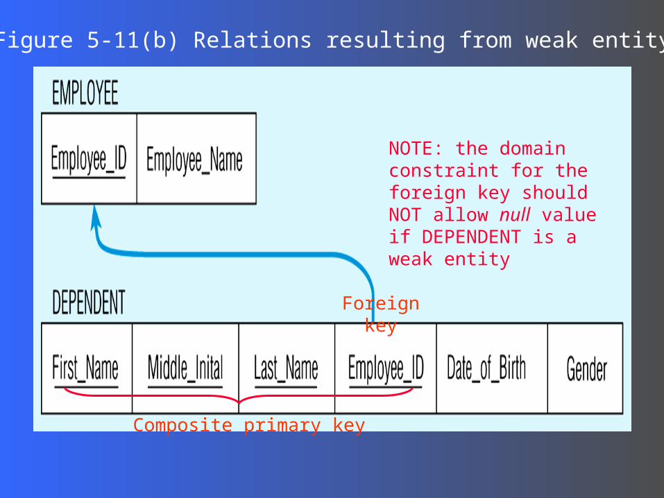
Figure 5-11(b) Relations resulting from weak entity
NOTE: the domain constraint for the foreign key should NOT allow null value if DEPENDENT is a weak entity
Foreign key
Composite primary key
Transforming EER Diagrams Transforming EER Diagrams into Relationsinto Relations
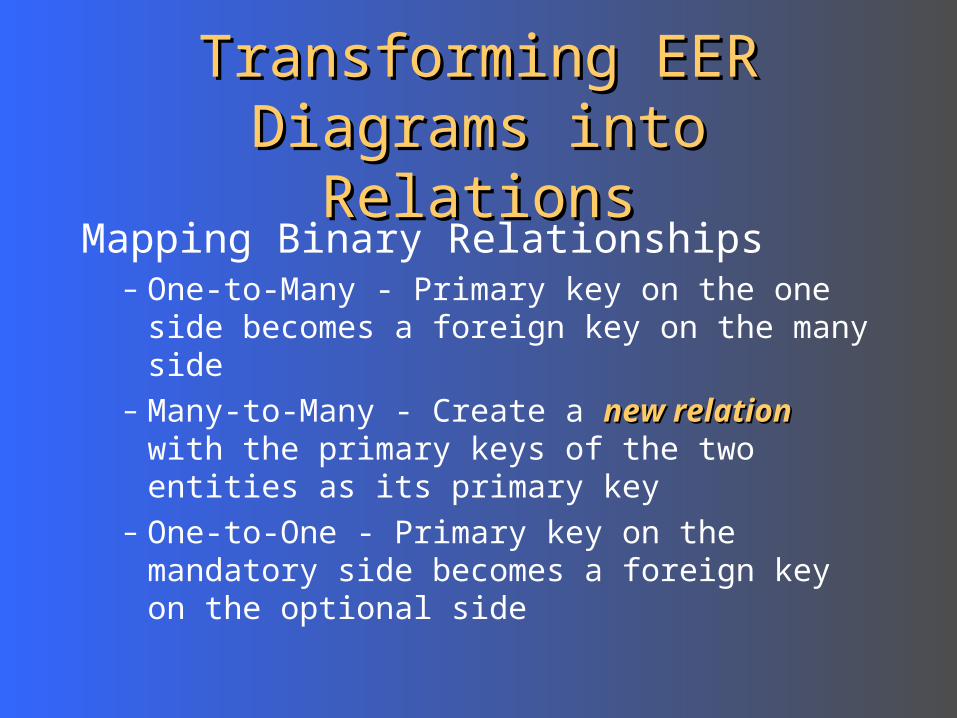
Mapping Binary Relationships– One-to-Many - Primary key on the one side
becomes a foreign key on the many side– Many-to-Many - Create a new relationnew relation with the
primary keys of the two entities as its primary key
– One-to-One - Primary key on the mandatory side becomes a foreign key on the optional side
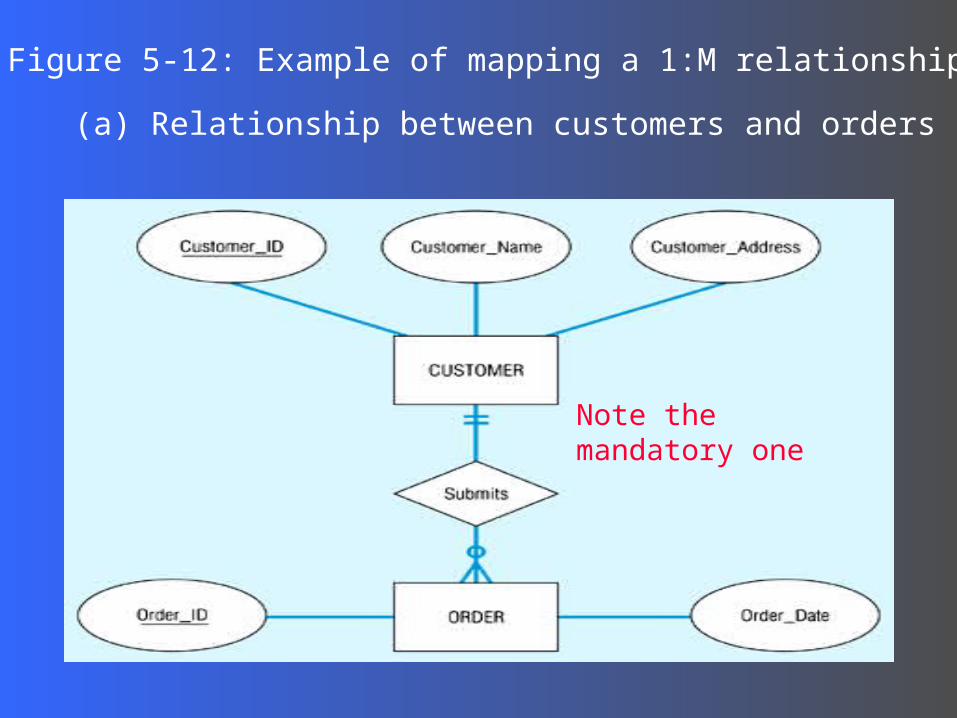
Figure 5-12: Example of mapping a 1:M relationship
(a) Relationship between customers and orders
Note the mandatory one
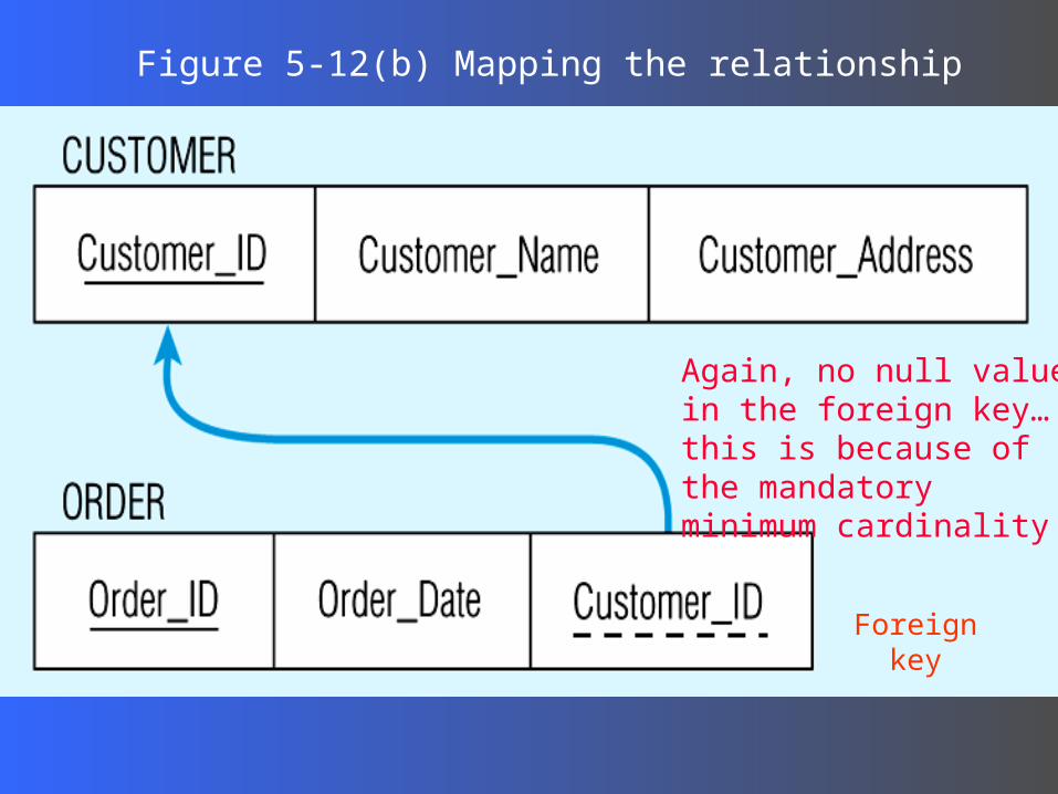
Figure 5-12(b) Mapping the relationship
Again, no null value in the foreign key…this is because of the mandatory minimum cardinality
Foreign key
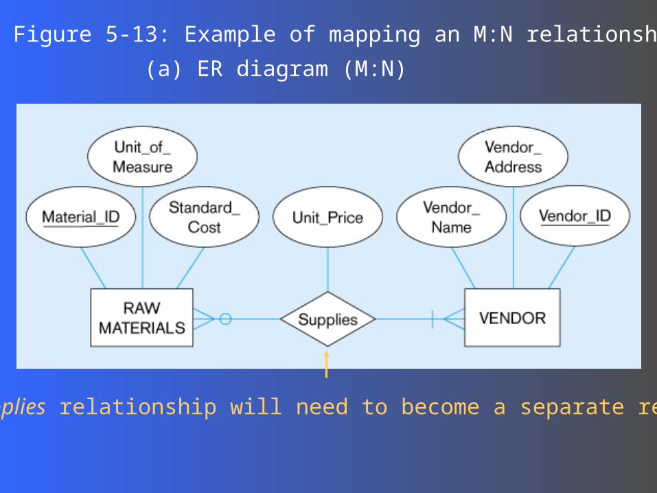
Figure 5-13: Example of mapping an M:N relationship
(a) ER diagram (M:N)
The Supplies relationship will need to become a separate relation
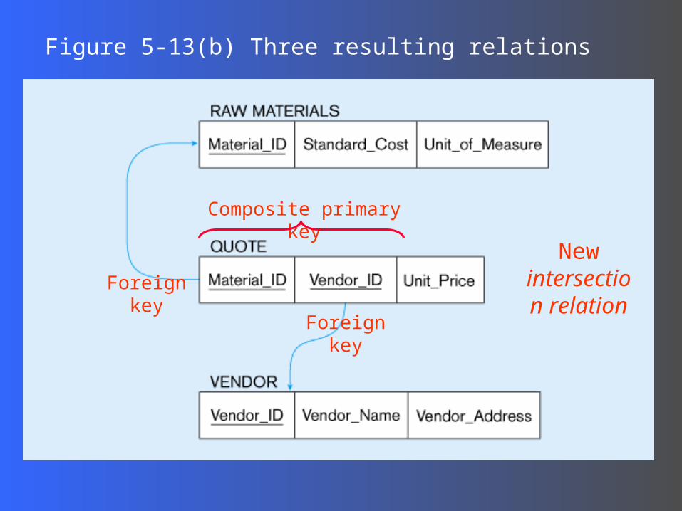
Figure 5-13(b) Three resulting relations
New intersection
relationForeign key
Foreign key
Composite primary key
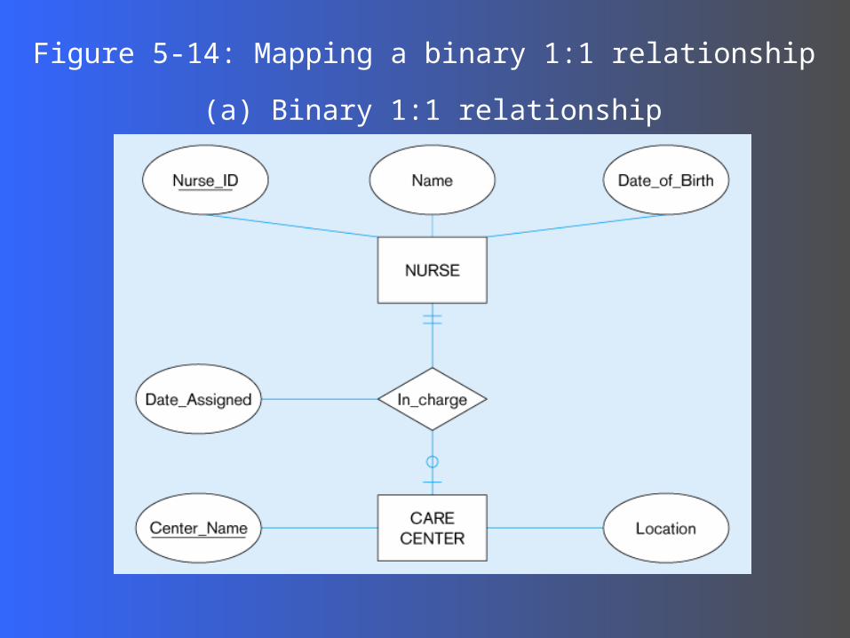
Figure 5-14: Mapping a binary 1:1 relationship
(a) Binary 1:1 relationship
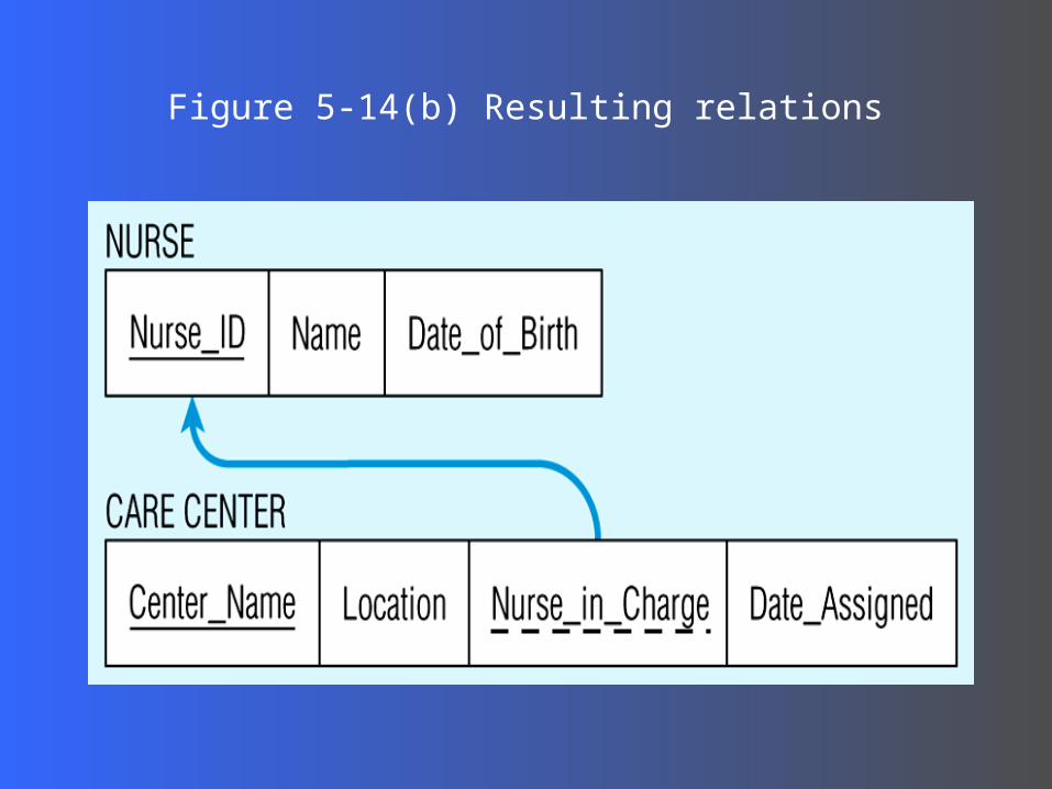
Figure 5-14(b) Resulting relations
Transforming EER Diagrams Transforming EER Diagrams into Relationsinto Relations
Mapping Associative Entities– Identifier Not Assigned
Default primary key for the association relation is composed of the primary keys of the two entities (as in M:N relationship)
– Identifier Assigned It is natural and familiar to end-usersDefault identifier may not be unique
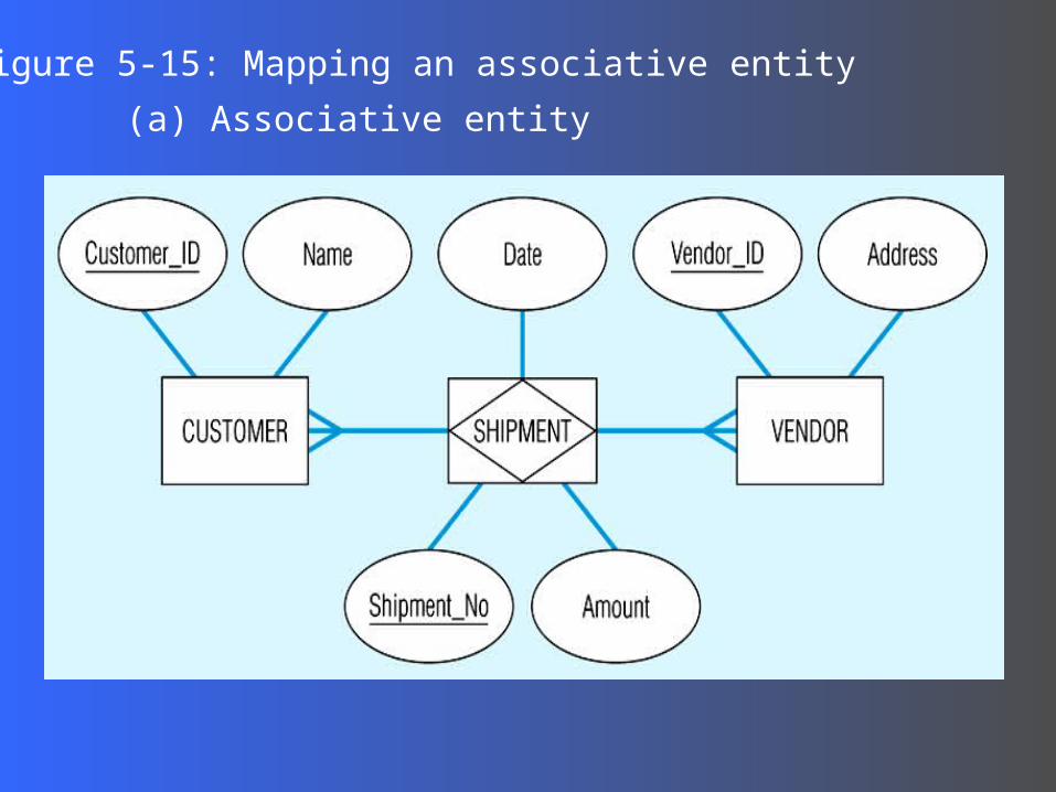
Figure 5-15: Mapping an associative entity
(a) Associative entity
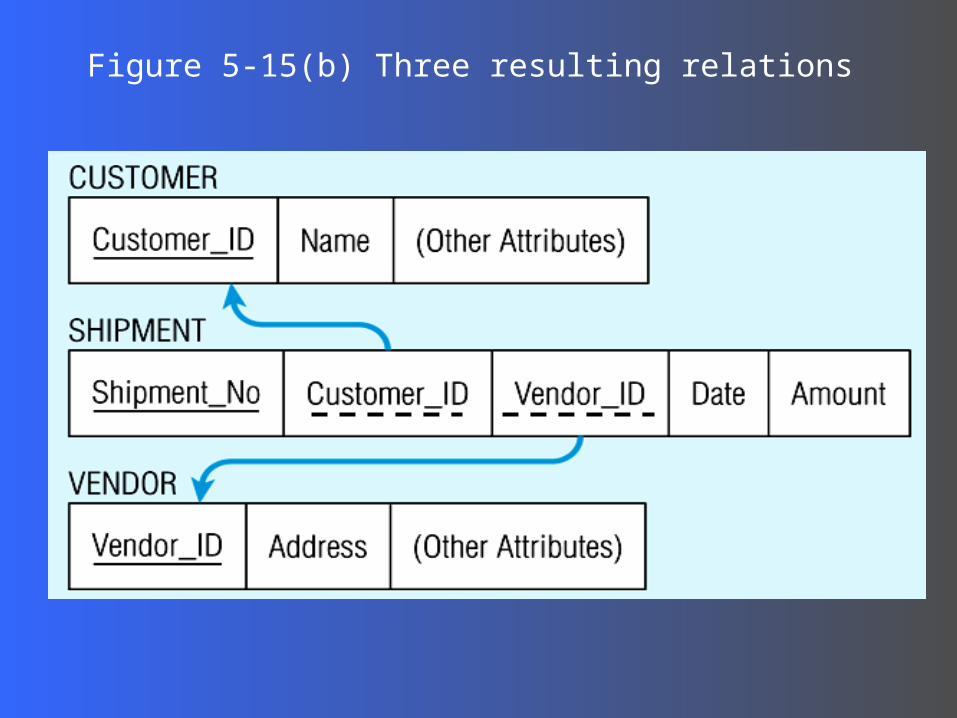
Figure 5-15(b) Three resulting relations

Transforming EER Diagrams Transforming EER Diagrams into Relationsinto Relations
Mapping Unary Relationships– One-to-Many - Recursive foreign key in the
same relation– Many-to-Many - Two relations:
One for the entity typeOne for an associative relation in which the
primary key has two attributes, both taken from the primary key of the entity
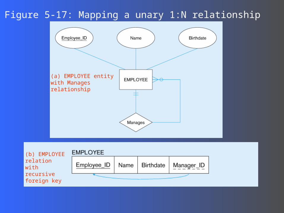
Figure 5-17: Mapping a unary 1:N relationship
(a) EMPLOYEE entity with Manages relationship
(b) EMPLOYEE relation with recursive foreign key
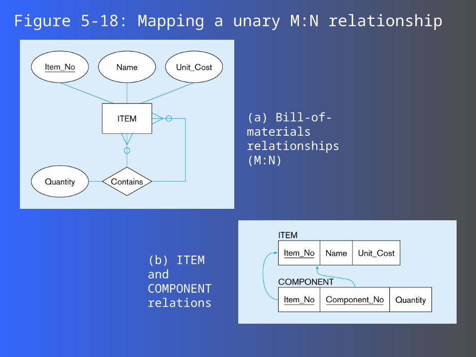
Figure 5-18: Mapping a unary M:N relationship
(a) Bill-of-materials relationships (M:N)
(b) ITEM and COMPONENT relations
Transforming EER Diagrams Transforming EER Diagrams into Relationsinto Relations
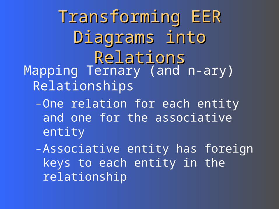
Mapping Ternary (and n-ary) Relationships– One relation for each entity and one
for the associative entity– Associative entity has foreign keys
to each entity in the relationship
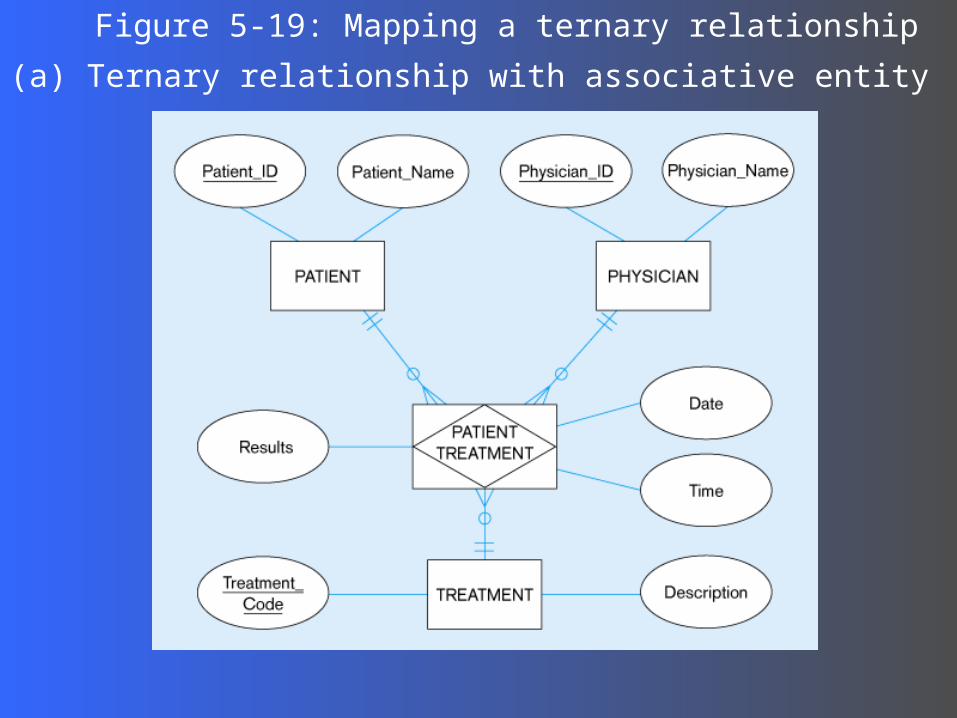
Figure 5-19: Mapping a ternary relationship
(a) Ternary relationship with associative entity
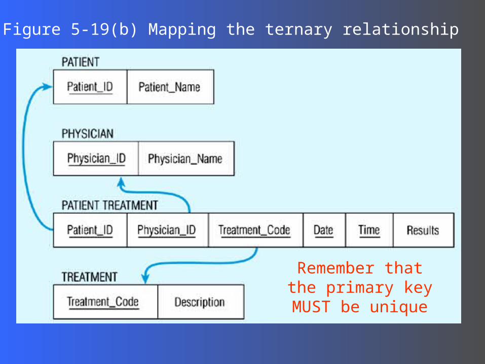
Figure 5-19(b) Mapping the ternary relationship
Remember that the primary key MUST be
unique
Transforming EER Diagrams Transforming EER Diagrams into Relationsinto Relations
Mapping Supertype/Subtype Relationships– One relation for supertype and for each subtype– Supertype attributes (including identifier and
subtype discriminator) go into supertype relation– Subtype attributes go into each subtype; primary
key of supertype relation also becomes primary key of subtype relation
– 1:1 relationship established between supertype and each subtype, with supertype as primary table
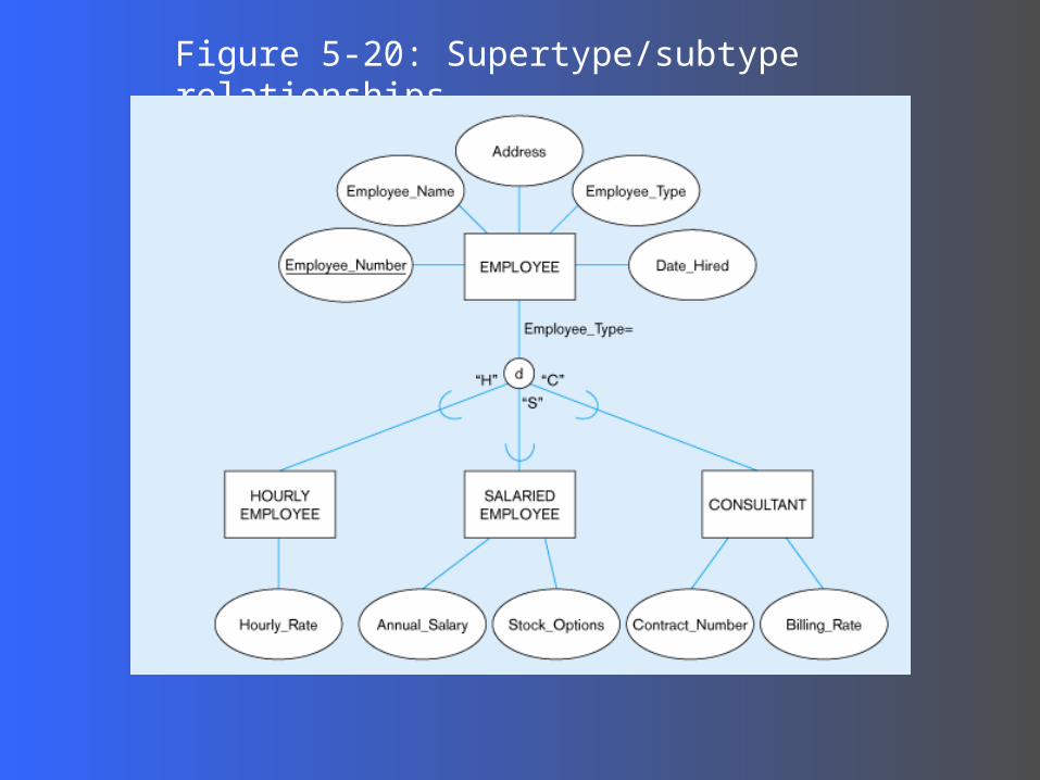
Figure 5-20: Supertype/subtype relationships
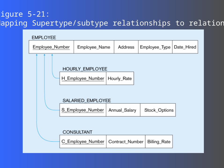
Figure 5-21: Mapping Supertype/subtype relationships to relations
Related Documents