Turkey Point Units 6 & 7 COL Application Part 2 — FSAR Revision 8 8-i CHAPTER 8: ELECTRIC POWER TABLE OF CONTENTS CHAPTER 8 ELECTRIC POWER .......................................................................... 8.1-1 8.1 INTRODUCTION ............................................................................................ 8.1-1 8.1.1 UTILITY GRID DESCRIPTION ................................................................ 8.1-1 8.1.4.3 Design Criteria, Regulatory Guides, and IEEE Standards .......... 8.1-1 8.2 OFFSITE POWER SYSTEM .......................................................................... 8.2-1 8.2.1 SYSTEM DESCRIPTION ......................................................................... 8.2-1 8.2.1.1 Transmission Switchyard ............................................................ 8.2-2 8.2.1.2 Transformer Area ........................................................................ 8.2-7 8.2.1.3 Switchyard Control Building ...................................................... 8.2-10 8.2.1.4 Switchyard and Transmission Line Testing and Inspection ...... 8.2-10 8.2.2 GRID STABILITY ................................................................................... 8.2-12 8.2.5 COMBINED LICENSE INFORMATION FOR OFFSITE ELECTRICAL POWER .................................................................................................. 8.2-14 8.2.6 REFERENCES....................................................................................... 8.2-15 8.3 ONSITE POWER SYSTEMS.......................................................................... 8.3-1 8.3.1.4 Inspection and Testing ................................................................ 8.3-3 8.3.2.2 Analysis ....................................................................................... 8.3-4 8.3.3 COMBINED LICENSE INFORMATION FOR ONSITE ELECTRICAL POWER .................................................................................................... 8.3-5 8.3.4 REFERENCES......................................................................................... 8.3-5

Welcome message from author
This document is posted to help you gain knowledge. Please leave a comment to let me know what you think about it! Share it to your friends and learn new things together.
Transcript
Turkey Point Units 6 & 7COL ApplicationPart 2 — FSAR
Revision 88-i
CHAPTER 8: ELECTRIC POWERTABLE OF CONTENTS
CHAPTER 8 ELECTRIC POWER .......................................................................... 8.1-1
8.1 INTRODUCTION ............................................................................................ 8.1-18.1.1 UTILITY GRID DESCRIPTION ................................................................ 8.1-1
8.1.4.3 Design Criteria, Regulatory Guides, and IEEE Standards .......... 8.1-18.2 OFFSITE POWER SYSTEM .......................................................................... 8.2-1
8.2.1 SYSTEM DESCRIPTION......................................................................... 8.2-18.2.1.1 Transmission Switchyard ............................................................ 8.2-28.2.1.2 Transformer Area ........................................................................ 8.2-78.2.1.3 Switchyard Control Building ...................................................... 8.2-108.2.1.4 Switchyard and Transmission Line Testing and Inspection ...... 8.2-10
8.2.2 GRID STABILITY ................................................................................... 8.2-128.2.5 COMBINED LICENSE INFORMATION FOR OFFSITE ELECTRICAL
POWER ..................................................................................................8.2-148.2.6 REFERENCES....................................................................................... 8.2-15
8.3 ONSITE POWER SYSTEMS.......................................................................... 8.3-18.3.1.4 Inspection and Testing ................................................................ 8.3-38.3.2.2 Analysis ....................................................................................... 8.3-4
8.3.3 COMBINED LICENSE INFORMATION FOR ONSITE ELECTRICAL POWER ....................................................................................................8.3-5
8.3.4 REFERENCES......................................................................................... 8.3-5

Turkey Point Units 6 & 7COL ApplicationPart 2 — FSAR
Revision 88-ii
CHAPTER 8 LIST OF TABLES
Number Title
8.1-201 Site-Specific Guidelines for Electric Power Systems
8.2-201 Grid Stability Interface Evaluation

Turkey Point Units 6 & 7COL ApplicationPart 2 — FSAR
Revision 88-iii
CHAPTER 8 LIST OF FIGURES
Number Title
8.2-201 Offsite Power System One-Line Diagram
8.2-202 Switchyard General Arrangement

Turkey Point Units 6 & 7COL ApplicationPart 2 — FSAR
Revision 88.1-1
CHAPTER 8 ELECTRIC POWER
8.1 INTRODUCTION
This section of the referenced DCD is incorporated by reference with the
following departures and/or supplements.
8.1.1 UTILITY GRID DESCRIPTION
Replace the existing information in DCD Subsection 8.1.1 with the following:
FPL owns and operates the power transmission system for Turkey Point
Units 6 & 7. FPL is the largest investor-owned electric utility in Florida, serving
more than 4.4 million customers. The FPL power transmission system consists of
transmission lines and substations that link the various generation facilities, load
centers, and grid interties within the FPL service territory at various voltages
ranging from 69 kV to 500 kV. FPL maintains multiple direct interconnections with
neighboring utilities. FPL also participates as a member of the Florida Reliability
Coordinating Council and the North American Electric Reliability Corporation.
The plant switchyard (Clear Sky substation) on the Turkey Point plant area is used
to transmit the electric power output from Units 6 & 7 to the FPL transmission
system. The switchyard also serves as the units' preferred and maintenance
source. The switchyard has two sections. The nominal operating voltage of these
sections is 230 kV and 500 kV. These sections are interconnected with 230 kV/
500 kV autotransformers. The 230 kV section of the plant switchyard is configured
in a breaker-and-a-half bus arrangement, whereas the configuration of the 500 kV
section of the switchyard is a double-breaker and a double-bus arrangement. The
transmission system is connected to the Clear Sky substation through two 500 kV
and two 230 kV transmission lines. Additionally, there is a 230 kV tie-line between
the Clear Sky substation and the Turkey Point substation.
8.1.4.3 Design Criteria, Regulatory Guides, and IEEE Standards
Add the following information between the second and third paragraph of this
subsection.
PTN SUP 8.1-1
PTN SUP 8.1-2

Turkey Point Units 6 & 7COL ApplicationPart 2 — FSAR
Revision 88.1-2
Offsite and onsite ac power systems' conformance to RGs and IEEE standards
identified by DCD Table 8.1-1 as site-specific and to other applicable RGs is as
indicated in Table 8.1-201.

Turkey Point Units 6 & 7COL ApplicationPart 2 — FSAR
Revision 88.1-3
Table 8.1-201Site-Specific Guidelines for Electric Power Systems
Criteria
Applicability (FSAR(a) Section/Subsection)
(a) “G” denotes guidelines as defined in NUREG-0800, Table 8-1 (SRP). No Letter denotes “Not applicable.”
Remarks
8.2 8.3.1 8.3.2
1. Regulatory Guides
a. RG 1.129 Maintenance, Testing, and Replacement of Vented Lead Acid Storage Batteries for Nuclear Power Plants
G Battery service tests are performed in accordance with the RG.
b. RG 1.155 Station Blackout Not applicable(b)
(b) Station Blackout and the associated guidelines were addressed as a design issue in the DCD.
c. RG 1.204 Guidelines for Lightning Protection of Nuclear Power Plants
G G
d. RG 1.206 Combined License Applications for Nuclear Power Plants (light water reactor edition)
G G G
2. Branch Technical Positions
a. BTP 8-3 (BTP ICSB-11 in DCD)
Stability of Offsite Power Systems
G Stability Analysis of the Offsite Power System is performed in accordance with the BTP.
PTN SUP 8.1-2

Turkey Point Units 6 & 7COL ApplicationPart 2 — FSAR
Revision 88.2-1
8.2 OFFSITE POWER SYSTEM
This section of the referenced DCD is incorporated by reference with the
following departure(s) and/or supplement(s).
8.2.1 SYSTEM DESCRIPTION
Delete the first, second, and sixth paragraphs and the first and last sentences of
the fourth paragraph, of DCD Subsection 8.2.1. Add the following information
before the fifth paragraph of DCD Subsection 8.2.1.
The offsite power system for Turkey Point Units 6 & 7 has four transmission lines
from the FPL transmission network to the plant switchyard (Clear Sky substation)
from three physically independent substations. The plant switchyard also includes
a normally open supply circuit from the existing Turkey Point substation serving
Turkey Point Units 1 through 5. This circuit provides an emergency source for
offsite power from Turkey Point substation in the event of loss of power in all four
transmission circuits to the plant switchyard.
The plant switchyard has two operating voltages with autotransformers
interconnecting the 500 kV and 230 kV sections. The Units 6 & 7 main step-up
transformers (GSU) and reserve auxiliary transformers (RAT) are connected at
230 kV to the plant switchyard. The interconnection of Units 6 & 7, the switchyard,
and the 230 kV and 500 kV transmission systems is shown on Figure 8.2-201 and
Figure 8.2-202.
There are two independent 500 kV transmission lines connected to the plant
switchyard, and two independent 230 kV transmission lines. As shown below,
each transmission line is tied into an FPL substation located between 19 and
52 miles from the plant. There is a 230 kV tie-line between the plant switchyard
and the Turkey Point substation which is within the Turkey Point plant property.
PTN COL 8.2-1

Turkey Point Units 6 & 7COL ApplicationPart 2 — FSAR
Revision 88.2-2
The transmission lines are divided into two separate transmission corridors. They
enter the common switchyard from different directions and are maintained in
separate rights-of-way. The two 500 kV lines and the Pennsuco 230 kV line are in
the west transmission corridor and the Davis 230 kV line and the 230 kV line to
Turkey Point substation are in the east transmission corridor.
The transmission lines are designed to meet all requirements of the National
Electric Safety Code (Reference 201). Transmission line structures and support
structures and systems are designed to the loading requirements of the NESC
and FPL standards. The transmission lines are designed with a basic insulation
level (BIL) that will minimize flashovers caused by lightning.
Galloping conductors are not anticipated.
A transformer area containing the main step-up transformer, the unit auxiliary
transformers, and reserve auxiliary transformers is located next to each turbine
building.
8.2.1.1 Transmission Switchyard
Replace the information in DCD Subsection 8.2.1.1 with the following information.
The 500 kV section of the plant switchyard is configured in a double-breaker and
double-bus arrangement to make two circuits for connecting two transmission
lines. Each 500 kV bus is connected to one 230 kV bus by separate 1500
megavolt ampere (MVA) autotransformers. High-side and low-side bank breakers
are provided for the autotransformers. All breakers are in the closed position and
Nominal Voltage (kV) Termination Point
Length(miles)
Thermal Rating(MVA)
500 Levee 500 kV 43 3464
500 Levee 500 kV 43 3464
230 Davis 230 kV 19 1191
230 Pennsuco 230 kV 52 1191
230 Turkey Point (normally open)
0.5 1191
PTN CDI
PTN COL 8.2-1

Turkey Point Units 6 & 7COL ApplicationPart 2 — FSAR
Revision 88.2-3
energized under normal operation. The 500 kV buses, circuit breakers and
disconnect switches are rated for a continuous current of 4000 A and a fault duty
rating of 50 kA.
The 230 kV buses, circuit breakers and disconnect switches are rated for a
continuous current of 4000 A and a fault duty rating of 63 kA.
The plant switchyard includes one terminal for the Unit 6 main step-up transformer
connection, one terminal for the Unit 7 main step-up transformer connection, two
terminals for connections to the Unit 6 reserve auxiliary transformers, and two
terminals for connections to the Unit 7 reserve auxiliary transformers.
Underground conductors are used to connect the main step-up and reserve
auxiliary transformers to the switchyard. The conductors for each transformer are
routed separately and are protected by reinforced concrete enclosures.
The configuration of the switchyard is shown in Figure 8.2-202.
The switchyard includes surge protective devices, grounding and a lightning
protection system in accordance with standard industry practice.
Failure Modes and Effects Analysis
The design of the offsite power system provides for a robust system that supports
reliable power production. While offsite power is not required to meet any safety
function, multiple, reliable transmission circuits are provided to support operation
of the Units 6 & 7 facilities. Neither the accident analysis nor the probabilistic risk
assessment has identified the nonsafety-related offsite power system as risk
significant for normal plant operation.
The offsite power system for Units 6 & 7 has four transmission lines from the FPL
transmission network to the plant substation from three physically independent
substations. No single transmission line is designated as the preferred circuit for
Unit 6 or for Unit 7. Each of the transmission lines has sufficient capacity and
capability from the transmission network to power the plant loads for both units
under normal, abnormal and accident conditions. Each 230 kV bus is split into
two sections by a bus breaker to prevent loss of both units with one bus out of
service (on clearance) and a trip of the other 230 kV bus.
PTN SUP 8.2-1

Turkey Point Units 6 & 7COL ApplicationPart 2 — FSAR
Revision 88.2-4
A failure modes and effects analysis of the Clear Sky substation confirms that a
single initiating event, such as transmission line fault plus a single breaker not
operating, does not cause failure of more than one single offsite transmission line,
or a loss of offsite power to either Units 6 or 7 onsite buses via the main step-up
transformer. This evaluation recognizes that a single failure of some switchyard
components could directly cause the loss of the switchyard feed to a unit’s main
step-up transformer such as a fault on this feed. Evaluated events include a
breaker not operating during a fault condition, a fault on a switchyard bus, a
spurious relay trip, or a loss of control power supply. In summary:
In the event of a fault on a 500 kV transmission line (or spurious relay
operation), the two associated line circuit breakers trip to isolate the line. All
other equipment remains energized.
In the event of a fault on a 500 kV transmission line with a stuck line breaker,
the breaker failure relay causes all circuit breakers on the affected bus to trip,
and thereby, de-energizes the affected bus and disconnect one
autotransformer. All other equipment remains energized.
In the event of a 500 kV bus fault, (or spurious relay operation), the breakers
associated with the affected bus trip, thereby isolating the faulted bus and
disconnecting one autotransformer. All other equipment remains energized.
In the event of a 500 kV bus fault with a stuck line breaker, the breaker failure
relay trips the adjacent line breaker and initiates transfer trip to the remote
substation to isolate the faulted bus and one 500 kV transmission line. All
other equipment remains energized.
In the event of a 500 kV bus fault with a stuck high-side autotransformer
breaker, the breaker failure relay trips the low-side autotransformer breaker to
isolate the faulted bus and the autotransformer. All other equipment remains
energized.
In the event of a fault on a 230 kV transmission line (or spurious relay
operation), the two associated circuit breakers trip to isolate the line and all
other equipment remains energized.
In the event of a fault on a 230 kV transmission line with a stuck center
position breaker, the breaker failure relay trips the adjacent breaker and
thereby isolating the faulted transmission line and de-energizing one reserve
auxiliary transformer. All other equipment remains energized.

Turkey Point Units 6 & 7COL ApplicationPart 2 — FSAR
Revision 88.2-5
In the event of a fault on a 230 kV transmission line with a stuck bus breaker,
the breaker failure relay causes all circuit breakers on the affected bus to trip
and thereby de-energize the affected bus. All other equipment remains
energized.
In the event of a 230 kV bus fault (or spurious relay operation), the breakers
associated with the affected bus trip, thereby isolating the faulted bus. All
other equipment remains energized.
In the event of a 230 kV bus fault with a stuck breaker, the breaker failure relay
trips the adjacent breaker to isolate the faulted bus. If the stuck breaker is
associated with either the Unit 6 or 7 main step-up connections, opening of the
adjacent breaker interrupts power to the associated main step-up and unit
auxiliary transformer resulting in the loss of both preferred and normal sources
of power to the unit. The switchyard feeds to the reserve auxiliary transformers
are still available.
In the event of a fault on one of the 500/230 kV autotransformers (or spurious
relay operation), the autotransformer bus breakers trip in the 500 kV and
230 kV switchyards to isolate the autotransformer. All other equipment
remains energized.
In the event of a fault on one of the 500/230 kV autotransformers with a stuck
bus circuit breaker, the breaker failure relay trips all the breakers on the
affected bus and thereby isolates the affected bus. All other equipment
remains energized.
Failure of protective relays or breaker trip coils or dc control power is
compensated for by redundant relays and breaker trip coils powered from
different dc sources, which allows the protective function to occur. (Failure of
protective relays or breaker trip coils or dc control power is automatically
detected and an alarm is given.)
The results of the above failure modes and effects analysis show that a single
fault in any section of the 230 kV or 500 kV bus is cleared by the adjacent
breakers and does not interrupt operation of the remaining part of the switchyard
bus or the connection of the unaffected transmission lines. A bus fault with a stuck
breaker associated with a main step-up transformer connection causes the loss of
preferred power to the associated Turkey Point unit. The switchyard feeds to the
reserve auxiliary transformers are still available. A bus fault concurrent with any
other stuck breaker does not cause a loss of power to either Unit 6 or 7.
Turkey Point Units 6 & 7COL ApplicationPart 2 — FSAR
Revision 88.2-6
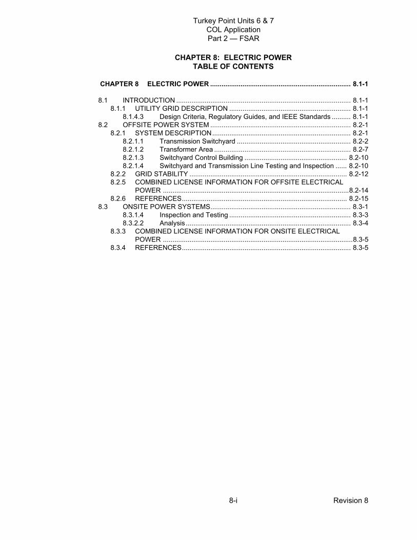
Transmission System Provider/Operator
FPL is the transmission system provider/operator and it constructs, owns, and
operates all substation and transmission facilities between the plant and the
points of interconnection to the grid. An interface agreement in accordance with
the North American Electric Reliability Corporation (NERC) Standard NUC-001- 01, between FPL Transmission & Substation-Power Supply Department and
Units 6 & 7 will establish the protocol to provide effective monitoring and oversight
of all grid, switchyard, and plant activities. These activities include maintenance,
testing, planned outages, load reductions, and emergent conditions that could
affect offsite power reliability. Department directives will implement the agreement
and will facilitate prompt and effective communications between the FPL power
supply system operator and Units 6 & 7 shift manager or unit supervisor.
Procedures will be established to ensure switchyard maintenance and design
changes are reviewed before implementation.
FPL uses a real-time contingency analysis computer program that is used by
FPL’s transmission system operators in determining the security level of the
transmission system by performing an analysis using a predefined set of
contingency criteria (e.g., single contingency). The computer program simulates a
list of active contingencies on the current power system and produces an output
of system conditions for each defined contingency. The program provides an
updated output approximately every 5 minutes using real-time system conditions
(e.g., real-time line outages, real-time flows and voltages, real-time breaker
status, etc.). For each defined contingency simulated, specified elements are
checked for limit violations (e.g. line overloads, voltage limits, and reactive limits at
generator buses). All contingencies that cause violations are output along with the
identification of the violations and information on the magnitude of the violation.
The current and previous outputs are displayed to determine degree of change as
compared to the previous contingency analysis output result.
A priority is also designated for each contingency. Violations of nuclear plant limits
are assigned the highest priority and if a violation is detected by the contingency
analysis computer program, it is reported at the top of the output violation list. The
computer program alerts the system operator of abnormal voltages, overloads, or
unit limitations that can be created by a loss of one or several elements of the
transmission system. The output of the contingency analysis computer program is
PTN SUP 8.2-2

Turkey Point Units 6 & 7COL ApplicationPart 2 — FSAR
Revision 88.2-7
used continuously by the operators to make critical decisions in response to
potential severe conditions.
Minimum and maximum voltage criteria specific to the Units 6 & 7 switchyard
buses will be documented in the interface agreement. The Units 6 & 7 agreement
will also specify that the Units 6 & 7 shift manager or unit supervisor be notified
within 15 minutes if a condition exists or is forecasted to exist (i.e., via contingency
analysis computer program) that would result in minimum or maximum switchyard
voltage requirements for Units 6 & 7 switchyard being exceeded. This agreement,
as well as the overall switchyard agreement, will require restoration of power to
Units 6 & 7 on a first-priority basis in the event of a loss of offsite power. The goal
for maximum restoration time will be 30 minutes.
8.2.1.2 Transformer Area
Add the following paragraph and subsections at the end of the
DCD Subsection 8.2.1.2.
The transformer area for each unit contains the main step-up transformers (three
single-phase transformers plus one spare), three unit auxiliary transformers, and
two reserve auxiliary transformers. The reserve auxiliary transformers are
connected to the 230 kV section of the switchyard. The 230 kV windings of the
main step-up transformer are connected in a wye configuration and connected to
the 230 kV section of the switchyard.
8.2.1.2.1 Switchyard Protection Relay Scheme
The switchyard’s relay protection schemes continuously monitor the conditions of
the power system and are designed to detect and isolate the faults with maximum
speed and minimum disturbance to the system. The schemes consist of primary
and secondary relaying systems that use separate instrument current
transformers for monitoring, separate trip circuits, and separate dc power supplies
to achieve redundancy in their protection functions. The principal features of the
schemes provided for different equipment are described below:
PTN COL 8.2-1
PTN COL 8.2-2
Turkey Point Units 6 & 7COL ApplicationPart 2 — FSAR
Revision 88.2-8
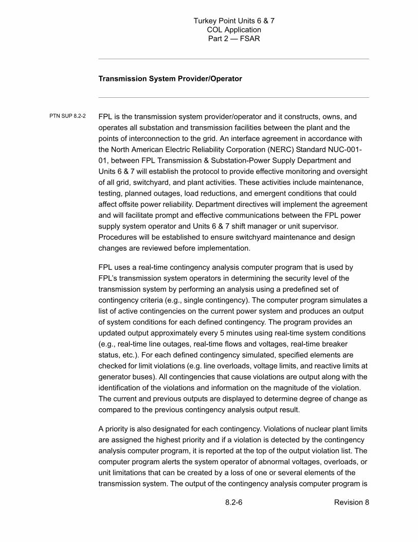
Each of the 500 kV and 230 kV transmission lines is protected by two
independent pilot systems that provide high-speed clearing for a fault
anywhere on the line.
The switchyard 500/230 kV autotransformers and switchyard buses have
primary and secondary protective relaying systems that provide high-speed
clearing for a fault within the switchyard.
The 230 kV circuits to the main step-up and reserve auxiliary transformers
have primary and secondary protective relaying systems located in the
switchyard control building that communicate via fiber optics to the associated
protective relaying system located in the plant.
Breaker failure relays are provided for all switchyard breakers to isolate a failed
breaker from all switchyard sources. In addition, for the switchyard breakers
connected to the main step-up and reserve auxiliary transformers, the remote
sources are isolated using direct transfer trip communication.
The protective devices controlling the switchyard breakers are set with
consideration given to preserving the plant grid connection following a turbine trip.
8.2.1.2.2 Plant Response to High Voltage Open Phase Condition
A monitoring system is installed on the credited GDC 17 offsite power circuit that
provides continuous open phase condition monitoring of the main step-up (MSU)
transformer high voltage (HV) input power supply (Reference 202). The system
detects an open phase condition (with or without a concurrent high impedance
ground on the HV side of the transformer) on one or more phases under all
transformer loading conditions. The open phase condition monitoring system
provides an alarm to the operators in the control room should an open phase
condition occur on the HV source to the MSU transformers. The system design
utilizes commercially available components including state of the art digital
relaying equipment and input parameters as required to provide loss of phase
detection and alarm capability.
Additionally, a high-voltage open phase condition with or without a ground fault
can manifest itself as an unacceptable voltage on the 6.9 kV medium voltage
ES-1 and ES-2 buses during normal loading conditions. The presence of
unacceptable voltages on the ES-1 and ES-2 buses results in isolation of the
affected medium voltage bus from the offsite power supply and enables the onsite
PTN SUP 8.2-4

Turkey Point Units 6 & 7COL ApplicationPart 2 — FSAR
Revision 88.2-9
standby diesel generators to start and restore AC power to the ES-1 and ES-2
buses and associated defense-in-depth loads. The onsite AC power system is
described in DCD Section 8.3.1.
Motor management relays for the medium voltage motors on ES-1 and ES-2
provide detection of unacceptably high negative sequence currents. High negative
sequence current motor trips or other running load trips provide alarms in the main
control room (MCR), which can assist in the detection of a high-voltage open
phase condition with or without a ground fault. Electric circuit protection for the
medium voltage system and equipment is described in DCD Section 8.3.1.1.1.1.
A high-voltage open phase condition with or without a ground fault can also
manifest itself as an unacceptable voltage on the 480 VAC low-voltage buses
powered from ES-1 and ES-2. The safety related IDS battery chargers are
powered from the low-voltage buses and continue to charge the IDS batteries
unless the battery charger input or output monitored electrical parameters are
unacceptable. If the monitored electrical parameters degrade to the point that the
battery charger no longer provides sufficient DC bus voltage, the Class 1E
electrical system DC bus receives power from the applicable IDS battery and the
battery charger maintains isolation between the Non-Class 1E AC and Class 1E
DC power systems which generates alarms in the MCR. The onsite AC power
system is described in DCD Section 8.3.1 and the Class 1E DC power system is
described in DCD Section 8.3.2.1.1.
Operator actions and maintenance and testing activities are addressed in
procedures, as described in Section 13.5. Plant operating procedures, including
off-normal operating procedures associated with the monitoring system, will be
developed prior to fuel load. Maintenance and testing procedures, including
calibration, surveillance testing, setpoint determination and troubleshooting
procedures associated with the monitoring system, will be developed prior to fuel
load.
Control Room operator and maintenance technician training associated with the
operation and maintenance of the monitoring system will be conducted in
accordance with the milestones for Non-Licensed Plant Staff and Reactor
Operator Training Programs in Table 13.4-201.

Turkey Point Units 6 & 7COL ApplicationPart 2 — FSAR
Revision 88.2-10
8.2.1.3 Switchyard Control Building
A control building within the switchyard houses redundant dc battery systems and
accommodates a sufficient number of relay and control panels to serve the
requirements of the switchyard.
The controls for switchyard breakers associated with the Units 6 & 7 main step-up
transformers are under the administrative control of the plant. The controls for
these breakers are located inside the plant.
The system control center of FPL transmission and substation operations has
operational control over the other breakers in the switchyard (including those
associated with the reserve auxiliary transformers).
The switchyard’s normal ac power is supplied from station service transformers
supplied by the tertiary windings of the 500/230 kV autotransformers. A backup
source of ac power to the switchyard is supplied from a plant source.
8.2.1.4 Switchyard and Transmission Line Testing and Inspection
FPL uses a process called The Phoenix Assurance Process to ensure the
installations of new, relocated, or modified facilities are fully operational before
being placed into service. The purpose of this process is to provide the
procedures used for equipment installation and collection of installation/
commissioning data. This assurance documentation is compiled into an
assurance book for each facility and serves as a source of baseline data for
installations. The objective of Phoenix is fourfold: safety (zero injuries), facilities
operate correctly after they are put into service, no rework associated with the
installation of facilities, and documentation for new assets are recorded, and
lessons learned are passed on for future reference.
It is the responsibility of personnel involved in the engineering, procurement,
construction, installation, and commissioning of new equipment to supply proper
documentation based on the requirements of the Phoenix Assurance Process.
The Phoenix Assurance Process covers acceptance, commissioning, and in-
service testing for new equipment and defines the responsibility of each
responsible person associated with the project. An individual, station-specific
PTN COL 8.2-1

Turkey Point Units 6 & 7COL ApplicationPart 2 — FSAR
Revision 88.2-11
book is assembled, incorporating, for each component, the specific procedures,
FPL quality assurance checklists, and forms prepared for the purpose of ensuring
equipment is ready for service.
The transmission switchyard interface agreement will specify that grid
maintenance and testing activities that could affect offsite power reliability be
closely coordinated with Units 6 & 7. This agreement will clearly state that the
plant switchyard equipment is maintained by FPL transmission and substation
operations.
FPL transmission and substation operations will conduct regular inspections of
the plant switchyard and perform regular maintenance and necessary repair or
replacement of equipment.
For performance of maintenance, testing, calibration, and inspection, FPL follows
its own field test manuals, vendor manuals and drawings, and industry's
maintenance practices to comply with applicable NERC reliability standards.
FPL verifies that these test results demonstrate compliance and takes corrective
actions as necessary. FPL plans and schedules maintenance activities and
notifies the nuclear plant in advance.
The interconnecting switchyard, as well as other substation facilities, has multiple
levels of inspection and maintenance. They include the following:
Monthly walk-through and visual inspection.
Quarterly oil sampling of power transformers at generating stations. Oil
samples are tested for dissolved gas analysis and oil quality.
Power circuit breakers are inspected and maintained according to the number
of operations and length of time in service, in accordance with the breaker
manufacturer's recommendations.
Doble power testing on power transformers.
Infrared testing on bus and equipment to identify hot spots.
Relay functional tests.
Turkey Point Units 6 & 7COL ApplicationPart 2 — FSAR
Revision 88.2-12
8.2.2 GRID STABILITY
Add the following information at the end of DCD Subsection 8.2.2.
The Florida Reliability Coordinating Council (FRCC) is the approving grid
organization for reliability studies performed on the area bulk electric system. FPL,
as the transmission service provider and member of the FRCC, conducts ongoing
planning studies of the transmission grid. Model data used to perform simulation
studies of projected future conditions is maintained and updated as load forecasts
and future generation/transmission changes evolve. Studies are performed
annually to assess future system performance in accordance with NERC reliability
standards. These studies form a basis for identifying future transmission
expansion needs. New, large generating units requesting to connect to the area
bulk electric system are required to complete the large generator interconnection
procedure. The studies performed by FPL as part of this procedure examine the
generating unit (combined turbine generator-exciter), the main step-up
transformer(s), the switchyard to which the generators are connected, and the
transmission system.
FPL performed the required studies to provide an analysis of the stability of the
grid with the Units 6 & 7 nuclear units interconnected and integrated into the FPL
transmission system. The analysis included an assessment of how the generators
and system would perform following potential severe disturbances.
Models used for the analysis were based on the latest available load forecasts,
generation expansion plan and system plans for 10 years into the future. As the
load forecasts and system plans are updated (e.g., topological changes,
generation retirements or additions), the performance of the system is reviewed
as part of the normal transmission system assessment to ensure compliance with
NERC and FRCC reliability standards and the effectiveness of the transmission
plan.
The performance of the grid stability analysis study consisted of dynamic
simulation and power flow analysis of the post-transient condition for each case
examined. The simulation results were analyzed for any sign of instability,
protective relay action, load shedding, voltage, or line-loading violations.
A dynamic stability analysis was conducted to assess the response of the
transmission system to various system disturbances. The grid stability study
examined the following contingencies:
PTN COL 8.2-2

Turkey Point Units 6 & 7COL ApplicationPart 2 — FSAR
Revision 88.2-13
Loss of the largest source
Loss of the most critical transmission circuit
Loss of the largest load
Grid stability following turbine trip (minimum of 3 seconds)
Breaker failure
Dynamic simulations were performed using the latest available FY 2007 FRCC
2017 summer peak base case scaled to 2020 peak load and average (60 percent
of peak) load levels combined with the NERC Multiregional Modeling Working
Group, FY 2006, 2012 stability case for the southern region with existing
commitments of all of the companies in Florida. The study cases assumed the
connection of the Units 6 & 7 and attendant incremental facilities in the base case.
Units 6 & 7 were modeled as two generating units, each with a rating of 1389 MVA
connected at 230 kV to the Clear Sky substation.
Study cases were selected to identify system performance under stressed but
likely scenarios. An off-peak load level is the more stressed scenario for stability.
Conditions more likely to occur at summer peak load and average load
(approximately 60 percent of summer peak) were considered.
The simulation results were analyzed for any sign of instability, protective relay
action, or load shedding. The simulation results showed that the Units 6 & 7 plant
and transmission system responses to the contingency events were acceptable.
Power flow analysis of the post transient condition for each case was performed.
This analysis was used to assess whether the event causes any voltage or line-
loading violations.
The study was conducted by performing steady-state and transient stability
analyses. Cases studied included loss of the largest source, loss of the most
critical transmission circuit, loss of the largest load, grid stability following turbine
trip (minimum of 3 seconds), and breaker failure. The performance of the system
complies with NERC reliability standards for normal TPL-001-0 Category A, single
contingency TPL-002-0 Category B, multiple contingency TPL-003-0 Category C,
and extreme bulk electric system events TPL-004-0 Category D. The simulation
results were analyzed for any sign of instability, protective relay action, load
shedding, voltage or line-loading violations.

Turkey Point Units 6 & 7COL ApplicationPart 2 — FSAR
Revision 88.2-14
The results of the grid stability analysis study do not indicate a loss of electric
power from any remaining supplies as a result of, or coincident with, the loss of
power generated by the nuclear power units or the loss of power from the
transmission network.
In order to maintain reactor coolant pump operation for three seconds following a
turbine trip as specified in DCD Subsection 8.2.2, the grid voltage at the high-side
of the GSU and RATs cannot dip more than 0.15 p.u. from the pre-trip steady-state
voltage. The results of turbine trip simulations demonstrate that the voltage and
frequency of the 230 kV switchyard buses remain within the limits required to
maintain reactor coolant pump operation for at least 3 seconds following a turbine
trip in either Unit 6 or 7.
Table 8.2-201 confirms that the interface requirements for steady-state load,
inrush kVA for motors, nominal voltage, allowable voltage regulation, nominal
frequency, allowable frequency fluctuation, maximum frequency decay rate, and
the limiting under frequency value for the reactor coolant pump have been met.
For the period from January 1, 1988, through September 30, 2008, the average
grid availability for the eight 230 kV lines from the existing Turkey Point substation
and two 500 kV lines from Levee substation in the FPL system is approximately
99.8 percent with only 48 forced outages lasting more than one hour. The average
frequency of forced line outages is approximately 1.4 line outages per year for
these transmission lines. The majority of the outages where the cause was
recorded were due to environmental conditions and equipment malfunction. Other
causes for outages were foreign intervention, human error, and relay
misoperation.
8.2.5 COMBINED LICENSE INFORMATION FOR OFFSITE ELECTRICAL POWER
This COL Item 8.2-1 is addressed in Subsections 8.2.1, 8.2.1.1, 8.2.1.2, 8.2.1.3,
and 8.2.1.4.
PTN SUP 8.2-3
PTN COL 8.2-1

Turkey Point Units 6 & 7COL ApplicationPart 2 — FSAR
Revision 88.2-15
This COL Item 8.2-2 is addressed in Subsections 8.2.1.2.1 and 8.2.2.
8.2.6 REFERENCES
201. Institute of Electrical and Electronics Engineers, National Electric Safety Code, C2-2007.
202. NRC Bulletin 2012-01, Design Vulnerability in Electric Power System, July
27, 2012.
PTN COL 8.2-2

Turkey Point Units 6 & 7COL ApplicationPart 2 — FSAR
Revision 88.2-16
*Based on the inrush of a single 10,000 HP feedwater pump assuming efficiency = 0.95, pf = 0.9, andinrush = 6.5 x FLA**Applicable to Turbine Trip Only. The maximum allowable voltage dip from the pre-event steady state voltage value during the 3-second turbine trip transient event as measured at the point of connection to the high side of the generator step-up transformer and the reserve auxiliary transformer.
Table 8.2-201Grid Stability Interface Evaluation
DCD Table 1.8-1 Item 8.2 Parameter
WEC Offsite AC Requirement
Turkey Point Units 6 & 7 Value Assumed
Steady-state load “normal running values provided as input to grid stability”
Load in each Unit =
(100 +j 60) MVA
Inrush kVA for motors 56,712 kVA* 56,712 kVA*
Nominal voltage Not provided 230 kV
Allowable voltage regulation 0.95-1.05 p.u. steady state 0.15 p.u. transient dip**
0.95-1.05 p.u. steady state 0.15 p.u. transient dip**
Nominal frequency 60 Hz 60 Hz
Allowable frequency fluctuation ± 1/2 Hz indefinite ± 1/2 Hz indefinite
Maximum frequency decay rate 5 Hz/sec 5 Hz/sec
DCD Table 1.8-1 Item 8.2 Parameter
WEC Offsite AC Requirement
Turkey Point Units 6 & 7 Value Calculated
Limiting under frequency value for RCP
≥ 57.7 Hz ≥ 59.73 Hz

Turkey Point Units 6 & 7COL ApplicationPart 2 — FSAR
Revision 88.2-17
Figure 8.2-201 Offsite Power System One-Line DiagramPTN COL 8.2-1

Turkey Point Units 6 & 7COL ApplicationPart 2 — FSAR
Revision 88.2-18
Figure 8.2-202 Switchyard General ArrangementPTN COL 8.2-1

Turkey Point Units 6 & 7COL ApplicationPart 2 — FSAR
Revision 88.3-1
8.3 ONSITE POWER SYSTEMS
This section of the referenced DCD is incorporated by reference with the
following departures and/or supplements.
8.3.1.1.1 Onsite AC Power System
Add the following to the end of fourth paragraph of DCD Subsection 8.3.1.1.1.
The site-specific switchyard and transformer voltages are shown on Figure 8.2-
201.
8.3.1.1.2.3 Onsite Standby Power System Performance
Add the following text between the second and third paragraphs of
DCD Subsection 8.3.1.1.2.3.
The Turkey Point Units 6 & 7 site conditions provided in Sections 2.1 and 2.3 are
bounded by the standard site conditions used to rate both the diesel engine and
the associated generator in DCD Subsection 8.3.1.1.2.3.
Add the following subsection after DCD Subsection 8.3.1.1.2.3.
8.3.1.1.2.4 Operations, Inspection and Maintenance
Operation, inspection and maintenance (including preventive, corrective, and
predictive maintenance) procedures consider both the diesel generator
manufacturer’s recommendations and industry diesel working group
recommendations.
8.3.1.1.6 Containment Building Electrical Penetrations
Add the following text at the end of DCD Subsection 8.3.1.1.6.
PTN SUP 8.3-1
PTN SUP 8.3-2
STD COL 8.3-2

Turkey Point Units 6 & 7COL ApplicationPart 2 — FSAR
Revision 88.3-2
Procedures implement periodic testing of protective devices that provide
penetration overcurrent protection. A sample of each different type of overcurrent
device is selected for periodic testing during refueling outages. Testing includes:
Verification of thermal and instantaneous trip characteristics of molded case
circuit breakers.
Verification of long time, short time, and instantaneous trips of medium voltage
vacuum circuit breakers.
Verification of long time, short time, and instantaneous trips of low voltage air
circuit breakers.
Verification of Class 1E and non-Class 1E dc protective device characteristics
(except fuses) per manufacturer recommendations, including testing for
overcurrent interruption and/or fault current limiting.
Penetration protective devices are maintained and controlled under the plant
configuration control program. A fuse control program, including a master fuse list,
is established based on industry operating experience.
8.3.1.1.7 Grounding System
Replace the sixth paragraph of DCD Subsection 8.3.1.1.7 with the following
information.
A grounding grid system design within the plant boundary includes determination
of step and touch potentials and ensuring that they are within the acceptable limit
for personal safety. The soil resistivity test data for the soil samples from the
existing Turkey Point Unit has been analyzed and used in the grounding grid
system design. The engineered fill for the Units 6 & 7 will be similar to the existing
unit’s fill. The ground grid conductor size was determined using methodology
outlined in IEEE 80, IEEE Guide for Safety in AC Substation Grounding
(Reference 201) and a grid configuration for the site was created. The grid
configuration was modeled in conjunction with the soil model. The resulting step
and touch potentials are within the acceptable limits.
STD COL 8.3-2
PTN COL 8.3-1

Turkey Point Units 6 & 7COL ApplicationPart 2 — FSAR
Revision 88.3-3
8.3.1.1.8 Lightning Protection
Replace the third paragraph of DCD Subsection 8.3.1.1.8 with the following
information.
In accordance with IEEE 665-1995, IEEE Guide for Generating Station Grounding
(DCD Section 8.3, Reference 18), a lightning protection risk assessment for the
structures comprising the Units 6 & 7 was performed based on the methodology in
NFPA 780-2008, Standard for Installation of Lightning Protection Systems, 2008
Edition (Reference 202). Lightning protection is provided for the Units 6 & 7
structures in accordance with NFPA 780. The zone of protection is based on the
elevations and geometry of the structures. It includes the space covered by a
rolling sphere having a radius sufficient to cover the structure to be protected. The
zone of protection method is based on the use of ground masts, air terminals, and
shield wires. Either copper or aluminum is used for lightning protection. Lightning
protection grounding is interconnected with the station/switchyard grounding
system.
8.3.1.4 Inspection and Testing
Add the following text at the end of DCD Subsection 8.3.1.4
Procedures are established for periodic verification of proper operation of the
Onsite AC Power System capability for automatic and manual transfer from the
preferred power supply to the maintenance power supply and return from the
maintenance power supply to the preferred power supply.
8.3.2.1.1.1 Class 1E DC Distribution
Add the following text at the end of DCD Subsection 8.3.2.1.1.1.
No site-specific non-Class 1E dc loads are connected to the Class 1E dc system.
PTN COL 8.3-1
STD SUP 8.3-4
STD SUP 8.3-3
Turkey Point Units 6 & 7COL ApplicationPart 2 — FSAR
Revision 88.3-4
8.3.2.1.4 Maintenance and Testing
Add the following text at the end of DCD Subsection 8.3.2.1.4.
Procedures are established for inspection and maintenance of Class 1E and non-
Class 1E batteries. Class 1E battery maintenance and service testing is
performed in conformance with Regulatory Guide 1.129. Batteries are inspected
periodically to verify proper electrolyte levels, specific gravity, cell temperature,
and battery float voltage. Cells are inspected in conformance with IEEE 450, and
vendor recommendations.
The clearing of ground faults on the Class 1E dc system is also addressed by
procedure. The battery testing procedures are written in conformance with IEEE
450 and the Technical Specifications.
Procedures are established for periodic testing of the Class 1E battery chargers
and Class 1E voltage regulating transformers in accordance with the
manufacturer recommendations.
Circuit breakers in the Class 1E battery chargers and Class 1E voltage
regulating transformers that are credited for an isolation function are tested
through the use of breaker test equipment. This verification confirms the ability
of the circuit to perform the designed coordination and corresponding isolation
function between Class 1E and non-Class 1E components. Circuit breaker
testing is done as part of the Maintenance Rule program and testing frequency
is determined by that program.
Fuses/fuse holders that are included in the isolation circuit are visually
inspected.
Class 1E battery chargers are tested to verify current limiting characteristic
utilizing manufacturer recommendation and industry practices. Testing
frequency is in accordance with that of the associated battery.
8.3.2.2 Analysis
STD COL 8.3-2

Turkey Point Units 6 & 7COL ApplicationPart 2 — FSAR
Revision 88.3-5
Replace the first sentence of the third paragraph of DCD Subsection 8.3.2.2 with
the following:
The Class 1E battery chargers are designed to limit the input (ac) current to an
acceptable value under faulted conditions on the output side, however, the voltage
regulating transformers do not have active components to limit current; therefore,
the Class 1E voltage regulating transformer maximum current is determined by
the impedance of the transformer.
8.3.3 COMBINED LICENSE INFORMATION FOR ONSITE ELECTRICAL POWER
This COL item is addressed in Subsections 8.3.1.1.7 and 8.3.1.1.8.
This COL item is addressed in Subsections 8.3.1.1.2.4, 8.3.1.1.6 and 8.3.2.1.4.
8.3.4 REFERENCES
201. Institute of Electrical and Electronics Engineers, IEEE Guide for Safety in AC Substation Grounding, IEEE Std 80-2000, August 4, 2000.
202. National Fire Protection Association, Standard for the Installation of Lightning Protection Systems, NFPA 780, 2008 ed.
STD DEP 8.3-1
PTN COL 8.3-1
STD COL 8.3-2
Related Documents