TCP/IP Protocol Suite 1 Copyright © The McGraw-Hill Companies, Inc. Permission required for reproduction or display. Chapter 8 Address Resolution Protocol (ARP)

Welcome message from author
This document is posted to help you gain knowledge. Please leave a comment to let me know what you think about it! Share it to your friends and learn new things together.
Transcript

TCP/IP Protocol Suite 1 Copyright © The McGraw-Hill Companies, Inc. Permission required for reproduction or display.
Chapter 8
Address
Resolution
Protocol
(ARP)

TCP/IP Protocol Suite 2
OBJECTIVES: To make a distinction between logical address (IP address) and
physical address (MAC address).
To describe how the mapping of a logical address to a physical address can be static or dynamic.
To show how the address resolution protocol (ARP) is used to dynamically map a logical address to a physical address.
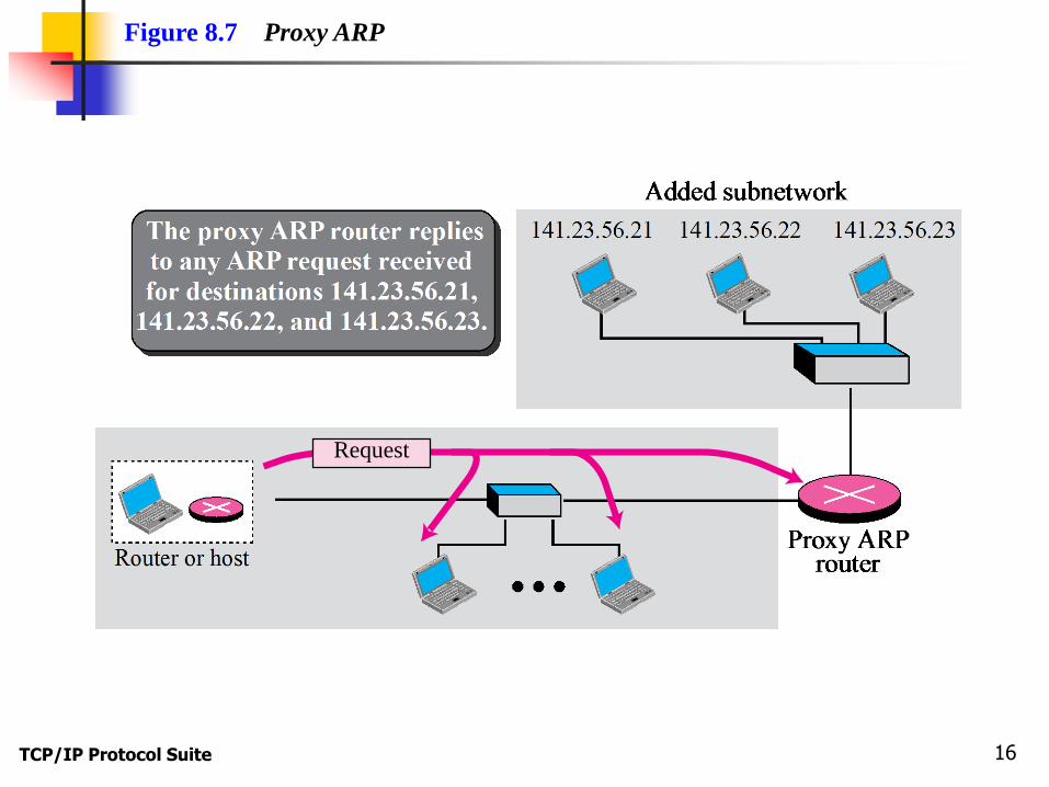
To show that the proxy ARP can be used to create a subnetting effect.
To discuss ATMARP, which maps the IP addresses when the underlying network is an ATM WAN.
To show that an ARP software package can be made of five components.
To show the pseudocode for each module used in the ARP software package.

TCP/IP Protocol Suite 3
Chapter
Outline

TCP/IP Protocol Suite 4
8-1 ADDRESS MAPPING
The delivery of a packet to a host or a router
requires two levels of addressing: logical and
physical. We need to be able to map a logical
address to its corresponding physical address and
vice versa. These can be done using either static or
dynamic mapping.

TCP/IP Protocol Suite 5
Topics Discussed in the Section
Static Mapping
Dynamic Mapping

TCP/IP Protocol Suite 6
8-2 ADDRESS MAPPING
Anytime a host or a router has an IP datagram to
send to another host or router, it has the logical (IP)
address of the receiver. But the IP datagram must
be encapsulated in a frame to be able to pass
through the physical network. This means that the
sender needs the physical address of the receiver. A
mapping corresponds a logical address to a physical
address. ARP accepts a logical address from the IP
protocol, maps the address to the corresponding
physical address and pass it to the data link layer.

TCP/IP Protocol Suite 7
Topics Discussed in the Section
Packet Format
Encapsulation
Operation
Proxy ARP

TCP/IP Protocol Suite 8
Figure 8.1 Position of ARP in TCP/IP protocol suite

TCP/IP Protocol Suite 9
Figure 8.2 ARP operation

TCP/IP Protocol Suite 10
Figure 8.3 ARP packet

TCP/IP Protocol Suite 11
Figure 8.4 Encapsulation of ARP packet
DataPreambleand SFD
Destinationaddress
Sourceaddress
Type CRC
8 bytes 6 bytes 6 bytes 2 bytes 4 bytes
Type: 0x0806

TCP/IP Protocol Suite 12
An ARP request is broadcast;
an ARP reply is unicast.
Note

TCP/IP Protocol Suite 13
Figure 8.5 Four cases using ARP

TCP/IP Protocol Suite 14
A host with IP address 130.23.43.20 and physical address
B2:34:55:10:22:10 has a packet to send to another host with IP
address 130.23.43.25 and physical address
A4:6E:F4:59:83:AB. The two hosts are on the same Ethernet
network. Show the ARP request and reply packets
encapsulated in Ethernet frames.
Solution Figure 8.6 shows the ARP request and reply packets. Note that
the ARP data field in this case is 28 bytes, and that the
individual addresses do not fit in the 4-byte boundary. That is
why we do not show the regular 4-byte boundaries for these
addresses. Also note that the IP addresses are shown in
hexadecimal.
Example 8.1

TCP/IP Protocol Suite 15
Figure 8.6 Example 8.1
TCP/IP Protocol Suite 16
Figure 8.7 Proxy ARP
Request

TCP/IP Protocol Suite 17
8-3 ATM ARP
We discussed IP over ATM in Chapter 7. When IP
packet are moving through an ATMWAN, a
mechanism protocol is needed to find (map) the
physical address of the exiting-point router in the
ATM WAN given the IP address of the router. This is
the same task performed by ARP on a LAN.
However, there is a difference between a LAN and
an ATM network. A LAN is a broadcast network (at
the data link layer); ARP uses the broadcasting
capability of a LAN to send (broadcast) an ARP
request.

TCP/IP Protocol Suite 18
Topics Discussed in the Section
Packet Format
ATMARP Operation
Logical IP Subnet (LIS)

TCP/IP Protocol Suite 19
Figure 8.8 ATMARP packet

TCP/IP Protocol Suite 20

TCP/IP Protocol Suite 21
The inverse request and inverse
reply messages can bind the
physical address to an IP
address in a PVC situation.
Note

TCP/IP Protocol Suite 22
Figure 8.9 Binding with PVC
time time
Two routers connected through PVC
I II IIIATM
Inverse Request
1
Inverse Reply2

TCP/IP Protocol Suite 23
Figure 8.10 Binding with ATMARP
Entering-pointrouter
Exiting-pointrouter
ATMARPServer
Time Time
I IIIIIATM
Using PVC or SVCconnection
Request1
Reply2
or
NACK2
Finding physical address

TCP/IP Protocol Suite 24
The request and reply message can be
used to bind a physical address to an
IP address in an SVC situation.
Note

TCP/IP Protocol Suite 25
The inverse request and inverse reply
can also be used to build the
server’s mapping table.
Note

TCP/IP Protocol Suite 26
Figure 8.11 Building a table
A newly connectedrouter
Time Time
I II III
ATMARP�serverATM
Inverse request1
Inverse reply2
TCP/IP Protocol Suite 27
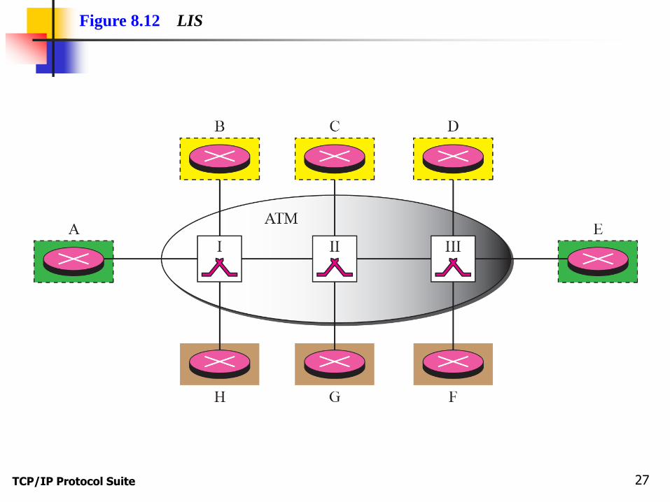
Figure 8.12 LIS

TCP/IP Protocol Suite 28
LIS allows an ATM network to be divided
into several logical subnets.
To use ATMARP, we need a separate
server for each subnet.
Note

TCP/IP Protocol Suite 29
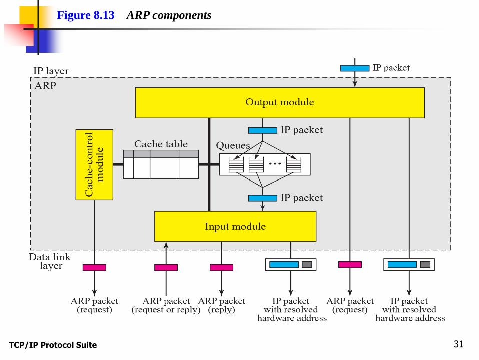
8-4 ARP PACKAGE
In this section, we give an example of a simplified
ARP software package. The purpose is to show the
components of a hypothetical ARP package and the
relationships between the components. Figure 8.13
shows these components and their interactions. We
can say that this ARP package involves five
components: a cache table, queues, an output
module, an input module, and a cache-control
module.
TCP/IP Protocol Suite 30
Topics Discussed in the Section
Cache Table
Queues
Output Module
Input Module
Cache-Control Module
TCP/IP Protocol Suite 31
Figure 8.13 ARP components

TCP/IP Protocol Suite 32

TCP/IP Protocol Suite 33

TCP/IP Protocol Suite 34
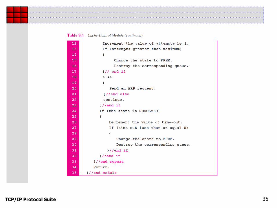
TCP/IP Protocol Suite 35

TCP/IP Protocol Suite 36

TCP/IP Protocol Suite 37
The ARP output module receives an IP datagram (from the IP
layer) with the destination address 114.5.7.89. It checks the
cache table and finds that an entry exists for this destination
with the RESOLVED state (R in the table). It extracts the
hardware address, which is 457342ACAE32, and sends the
packet and the address to the data link layer for transmission.
The cache table remains the same.
Example 8.2
TCP/IP Protocol Suite 38
Twenty seconds later, the ARP output module receives an IP
datagram (from the IP layer) with the destination address
116.1.7.22. It checks the cache table and does not find this
destination in the table. The module adds an entry to the table
with the state PENDING and the Attempt value 1. It creates a
new queue for this destination and enqueues the packet. It then
sends an ARP request to the data link layer for this destination.
The new cache table is shown in Table 8.6.
Example 8.3

TCP/IP Protocol Suite 39

TCP/IP Protocol Suite 40
Fifteen seconds later, the ARP input module receives an ARP
packet with target protocol (IP) address 188.11.8.71. The
module checks the table and finds this address. It changes the
state of the entry to RESOLVED and sets the time-out value to
900. The module then adds the target hardware address
(E34573242ACA) to the entry. Now it accesses queue 18 and
sends all the packets in this queue, one by one, to the data link
layer. The new cache table is shown in Table 8.7.
Example 8.4

TCP/IP Protocol Suite 41

TCP/IP Protocol Suite 42
Twenty-five seconds later, the cache-control module updates
every entry. The time-out values for the first three resolved
entries are decremented by 60. The time-out value for the last
resolved entry is decremented by 25. The state of the next-to-
the last entry is changed to FREE because the time-out is zero.
For each of the three pending entries, the value of the attempts
field is incremented by one. After incrementing, the attempts
value for one entry (the one with IP address 201.11.56.7) is
more than the maximum; the state is changed to FREE, the
queue is deleted, and an ICMP message is sent to the original
destination (see Chapter 9). See Table 8.8.
Example 8.5

TCP/IP Protocol Suite 43
Related Documents