2006 EDITION January 2006 Interchanges 7-1 Chapter 7 Interchanges 7.1 Introduction As discussed in Chapter 6, it is important that designers consider the needs and activities of the pedestrians, cyclists, and motorists to comprehensively plan for safe and convenient travel through intersections. In some instances it is not possible, due to safety, spatial constraints or other conditions, to accommodate all users within an at-grade intersection. In these cases, constructing an overpass bridge or underpass structure for the purpose of separating the intersecting facilities should be studied. An interchange can provide the greatest safety and capacity; however, interchanges may not fit well within the existing context and may complicate multimodal accommodation. This chapter focuses on interchanges to provide connectivity between these facilities. Grade separations without connecting ramps are discussed in Chapter 10. 7.2 Warrants and Planning Considerations Interchanges and grade separations occur when two or more roadways cross at different levels. A grade separation is a crossing of two roadways, a roadway and railroad, or a roadway and a pedestrian/bicycle facility at different levels. It eliminates crossing conflicts and improves operational efficiency. Grade separations alone do not provide connections or access between the intersecting roadways. Rather, traffic, cyclists and pedestrians on each intersecting roadway remain completely independent from each other. Interchanges provide access between the grade separated roadways by incorporating a network of ramps. Roadways employing interchanges are often freeways and major arterials, commonly referred to as “highways”

Welcome message from author
This document is posted to help you gain knowledge. Please leave a comment to let me know what you think about it! Share it to your friends and learn new things together.
Transcript

2006 EDITION
January 2006 Interchanges 7-1
Chapter 7
Interchanges
7.1 Introduction
As discussed in Chapter 6, it is important that designers consider the needs and activities of the pedestrians, cyclists, and motorists to comprehensively plan for safe and convenient travel through intersections. In some instances it is not possible, due to safety, spatial constraints or other conditions, to accommodate all users within an at-grade intersection. In these cases, constructing an overpass bridge or underpass structure for the purpose of separating the intersecting facilities should be studied. An interchange can provide the greatest safety and capacity; however, interchanges may not fit well within the existing context and may complicate multimodal accommodation. This chapter focuses on interchanges to provide connectivity between these facilities. Grade separations without connecting ramps are discussed in Chapter 10.
7.2 Warrants and Planning Considerations
Interchanges and grade separations occur when two or more roadways cross at different levels. A grade separation is a crossing of two roadways, a roadway and railroad, or a roadway and a pedestrian/bicycle facility at different levels. It eliminates crossing conflicts and improves operational efficiency. Grade separations alone do not provide connections or access between the intersecting roadways. Rather, traffic, cyclists and pedestrians on each intersecting roadway remain completely independent from each other. Interchanges provide access between the grade separated roadways by incorporating a network of ramps. Roadways employing interchanges are often freeways and major arterials, commonly referred to as “highways”

2006 EDITION
throughout this chapter. The following sections describe warrants and planning considerations for interchanges.
7.2.1 Warrants In many instances, the decision to provide a grade-separated interchange should be made based on careful consideration of a number of factors. These factors are referred to as warrants and include: 1. Design Designation – Once it is decided to develop a route as a
freeway, it should be determined whether each intersecting highway will be terminated, rerouted, or provided with a grade separation or interchange, the chief concern being continuous flow on the freeway.
2. Safety – The crash reduction benefits of an interchange may warrant its selection at a particularly dangerous at-grade intersection.
3. Congestion – An interchange may be warranted where the level of service of an at-grade intersection is unacceptable and the intersection cannot be modified to provide an acceptable level of service.
4. Site Topography – At certain sites, a grade separated interchange may be more feasible than an at-grade intersection due to local topographical conditions.
5. Traffic Volume – Interchanges are desirable at cross streets with heavy traffic volumes. The elimination of conflicts due to high crossing volume greatly improves the movement of traffic.
6. Road-User Benefits –When interchanges are designed and operated efficiently, they significantly reduce the travel time and costs when compared to at-grade intersections. Therefore, an interchange is warranted if an analysis reveals that road-user benefits will exceed the costs over the service life of the interchange.
Additional reasons for constructing interchanges include the need to provide access to areas not served by other means of access, such as High Occupancy Vehicle (HOV) facilities, highway rest areas, tourist information centers, and highway maintenance facilities.
7-2 Interchanges January 2006

2006 EDITION
7.2.2 Contextual Considerations for Interchanges In all cases, the designer should consider the relationship between the proposed interchange and the surrounding context as described below.
Does a grade separation currently exist?
How does the proposed interchange fit within the cultural, historical, aesthetic, and environmental character of the surrounding area?
Is sufficient right-of-way owned or controlled to construct and maintain the interchange? If not, is land available for acquisition to accommodate the project?
Does the existence of a high ground water elevation and/or poor soil conditions complicate the design and construction of the required structures?
If highway illumination is required to maintain adequate lighting levels for safety and/or security, is there a power source available to satisfy this need and is such lighting consistent with the surrounding context?
Will the introduction of continuous high speed traffic or increased roadway grades create high noise levels requiring the introduction of noise barriers?
Will the interchange result in substantial air quality improvements? Is mechanical ventilation required due to the physical and operational characteristics of the facility?
Will existing utility systems be impacted by the construction? Are provisions needed for future utilities required by area municipalities, agencies, and/or public and private utility companies?
Will elevating one roadway over another infringe upon abutter air rights or impact the operation of a nearby airport?
Are there unique requirements relative to horizontal and vertical clearances and/or utility crossings associated with the proposed grade separation?
Has the diversion of some or all of the activity been considered, thereby eliminating the need for grade separation?
January 2006 Interchanges 7-3

2006 EDITION
Will detours be required during construction and are existing routes available? Will temporary detour roadways, bridges, or staged construction be required?
7.2.3 Pedestrian and Bicycle Accommodation Through Interchanges Pedestrian and bicycle accommodation should be maintained through interchanges. In most cases, interchanges are provided between Interstate Highways and other roadways (referred to as the “minor road”). The pedestrian and bicycle accommodation, such as sidewalks, bicycle lanes, and shoulders, on the minor road should be maintained through the interchange area. If pedestrian and bicycle use is permitted on both roadways, then this principle applies to both facilities. Pedestrian and bicycle accommodation through interchanges is described throughout this chapter. A key factor for maintaining the continuity and safety of pedestrian and bicycle accommodation through interchanges is the configuration of the ramp/minor road intersection described in Section 7.7. As described in this section, diamond-type ramps and signalized ramp terminals are preferable in areas with high pedestrian and bicycle activity. In some instances it may be preferable to provide crossings of a limited-access roadway separate from an interchange. For example, an overpass or underpass connecting a route parallel to the one crossing at the interchange. This could be a smaller street without an interchange, or a dedicated bicycle and pedestrian crossing.
7.2.4 Interchange Selection Factors The decision to provide a grade separation without ramps rather than an interchange is often based on the following considerations:
Lacking a suitable relocation plan for the crossroad, a highway grade separation without ramps may be provided to maintain connectivity of low volume roadways. All users desiring to access one facility from the other are required to use other existing routes. In some instances these users may have to travel a considerable distance, particularly in rural areas.
Promotion of access to areas not served by frontage roads or other means of access, physically separating railroad grade crossings, providing access to HOV facilities, providing access to concentrations
7-4 Interchanges January 2006

2006 EDITION
of pedestrian traffic (for instance park developed on both sides of a major arterial), and allowing the passage of bicycles.
A grade separation without interchange ramps may be provided to avoid having interchanges so close to each other that signing and operation would be difficult. This approach eliminates interference with large major road interchanges and increases safety and mobility by concentrating turning traffic at a few points where it is feasible to provide adequate ramp systems. On the other hand, undue concentration of turning movements at one location should be avoided where it would be better to have additional interchanges.
In rugged topography the site conditions at an intersection may be more favorable for provision of a grade separation than an at-grade intersection. If ramp connections are difficult or costly, it may be practical to omit them at the structure site and accommodate turning movements elsewhere by way of other intersecting roads.
Many times partial interchanges are constructed initially because the traffic volumes do not support a full interchange or the required right-of-way is not available when the interchange is first constructed. As time passes however, the need for a complete interchange may develop or the right-of-way may be obtained.
7.2.5 Application to Freeways and Highways with Full Access Control When full access control is proposed for an existing highway, or a new freeway is proposed, each intersecting public or private way must be handled using one of the following options. The options listed below also apply to pedestrian and bicycle facilities.
The intersecting facility can be dead-ended effectively terminating through traffic;
The intersecting facility can be re-routed to maintain connectivity;
The intersecting facility can be grade separated as either an underpass or an overpass, maintaining through traffic but effectively terminating access to the intersecting highway;
The intersecting facility can be reconstructed as an interchange, to maintain through traffic access to the freeway.
The importance of the continuity of the crossing road or the feasibility of an alternate route will determine whether a grade separation or
January 2006 Interchanges 7-5
2006 EDITION
interchange is warranted. An interchange should be provided on the basis of the anticipated demand for access to the minor road and the operational effects on the major roadway.
7.2.6 Interchange Spacing Interchange spacing is an important consideration in the planning and design of new or modified interchanges. Interchange spacing is the distance measured along the main roadway between the centerlines of the intersecting roadways that maintain ramp access to the through highway. In urban areas, there should be a one-mile minimum spacing between interchanges to allow sufficient space for entrance and exit maneuvers. Closer spacing may require the use of collector-distributor roads to remove the merging/diverging and accelerating/decelerating traffic from the freeway mainline. In rural, undeveloped areas, interchanges should be spaced no closer than three miles apart. These spacing guidelines are intended to minimize the disruption of entering and exiting traffic to the mainline of the highway and to prevent insufficient sign spacing.
7.2.7 Interchange Justification/Modification Reports The design and construction of interchanges or grade separations along Interstate highways is controlled by the Federal Highway Administration (FHWA) and requires their approval and conformance to their requirements regarding modifications to and maintenance of the Interstate system. An Interchange Justification Report (IJR) / Interchange Modification Report (IMR) is required for new interchanges or modifications to existing interchanges. The designer should consult with FHWA for their latest policy for preparing an IJR/IMR. The policy is applicable to new or revised access points to existing Interstate facilities, and to all NHS freeway facilities. The policy in force at the time of this printing is: It is in the national interest to maintain the Interstate System to provide the highest level of service in terms of safety and mobility. Adequate control of access is critical to providing such service. Therefore, new or revised access points to the existing Interstate System should meet the following requirements:
Interchange justification and modification requires approval from the Federal Highway Administration.
7-6 Interchanges January 2006
2006 EDITION
1. The existing interchanges and/or local roads and street in the corridor can neither provide the necessary access nor be improved to satisfactorily accommodate the design-year traffic demands while at the same time providing the access intended by the proposal.
2. All reasonable alternatives for design options, location and transportation system management type improvements (such as ramp metering, mass transit, and HOV facilities) have been assessed and provided for if currently justified, or provisions are included for accommodating such facilities if a future need is identified.
3. The proposed access point does not have a significant adverse impact on the safety and operation of the Interstate facility based on an analysis of current and future traffic. The operational analysis for existing conditions shall, particularly in urbanized areas, include an analysis of sections of Interstate to and including at least the first adjacent existing or proposed interchange on either side. Crossroads and other roads and streets shall be included in the analysis to the extent necessary to assure their ability to collect and distribute traffic to and from the interchange with new or revised access points.
4. The proposed access connects to a public road only and will provide for all traffic movements. Less than “full interchanges” for special purpose access for transit vehicles, for HOVs, or into park and ride lots may be considered on a case-by-case basis. The proposed access will be designed to meet or exceed current standards for Federal-aid projects on the Interstate System.
5. The proposal considers and is consistent with local and regional land use and transportation plans. Prior to final approval, all requests for new or revised access must be consistent with the metropolitan and/or statewide transportation plan, as appropriate, the applicable provision of 23 CFR part 450 and the transportation conformity requirements of 40 CFR parts 51 and 93.
6. In areas where the potential exists for future multiple interchange additions, all requests for new or revised access are supported by a comprehensive Interstate network study with recommendations that address all proposed and desired access within the context of a long-term plan.
7. The request for a new or revised access generated by new or expanded development demonstrates appropriate coordination between the development and related or otherwise required transportation system improvements.
January 2006 Interchanges 7-7

2006 EDITION
8. The request for new or revised access contains information relative to the planning requirements and the status of the environmental processing of the proposal.
The following is a description of the information typically included in an IJR or IMR submitted to the FHWA:
A clear description of the location and type of proposed new or modified access. Maps, schematic diagrams, and preliminary design plans should be included as needed to clearly describe the proposal. Drawings and plans should include (as applicable): project limits, adjacent interchanges, proposed interchange configuration, travel lanes and shoulder widths, ramps to be added, ramps to be removed, ramp radii, ramp grades, acceleration lane lengths, deceleration lane lengths, taper lengths, auxiliary lane lengths, "taper" or "parallel" type exit ramps, truck climbing lanes, and collector/distributor roads.
Purpose and need for the new or revised access points (why it is needed, what are the intended benefits).
Any background or supporting information that further explains the basis for the proposal (i.e., new highway proposed, planned private developments, known public support, etc.). Maps should show exact locations of all developments. If the purpose of the IMR/IJR is to support one or more proposed developments, the IMR/IJR should say so.
If the interchange is within a Transportation Management Area.
If there are any known issues of concern or controversy (environmental, public opposition, etc.).
A description of the design alternatives considered (diamond interchange, single-point, directional ramps, alternate locations, etc.) and why the proposed alternative was selected.
Status of environmental studies/permitting process.
Estimated costs of the project, proposed funding sources (private development, local funds, State or Federal-aid funds), and implementation schedule.
Relationship and distance of the interchange to adjacent interchanges and the ability to provide adequate signing.
7-8 Interchanges January 2006
2006 EDITION
Any necessary design exceptions from currently adopted AASHTO Interstate design standards.
Existing and Proposed Limits of Access.
Schematic drawings showing current and design year traffic volumes for the mainline, ramps, and cross roads.
Additional proposed traffic signalization, roundabout construction and signing (if applicable).
Safety issues regarding the existing conditions and proposed alternatives.
7.3 Interchange Types
There are a variety of interchange types available for the conditions encountered. After the decision has been made that an interchange is appropriate for the location, the selection of interchange type is influenced by factors such as operational effects on the mainline and cross street, context sensitivity, multimodal accommodation, topography, potential site impacts, required right-of-way, cost, and anticipated activity levels. Each interchange must be designed to fit individual site conditions. The final design may be a minor or major modification of one of the basic types, or it may be a combination of the basic types. Freeway interchanges are of two general types: A system interchange will connect freeway to freeway; a service interchange will connect a freeway to a lesser facility. System interchanges are most frequently three-leg, full cloverleaf, or directional interchanges. Service interchanges are most frequently diamond, cloverleaf, or partial cloverleaf interchanges. These basic interchange configurations are described in the following sections.
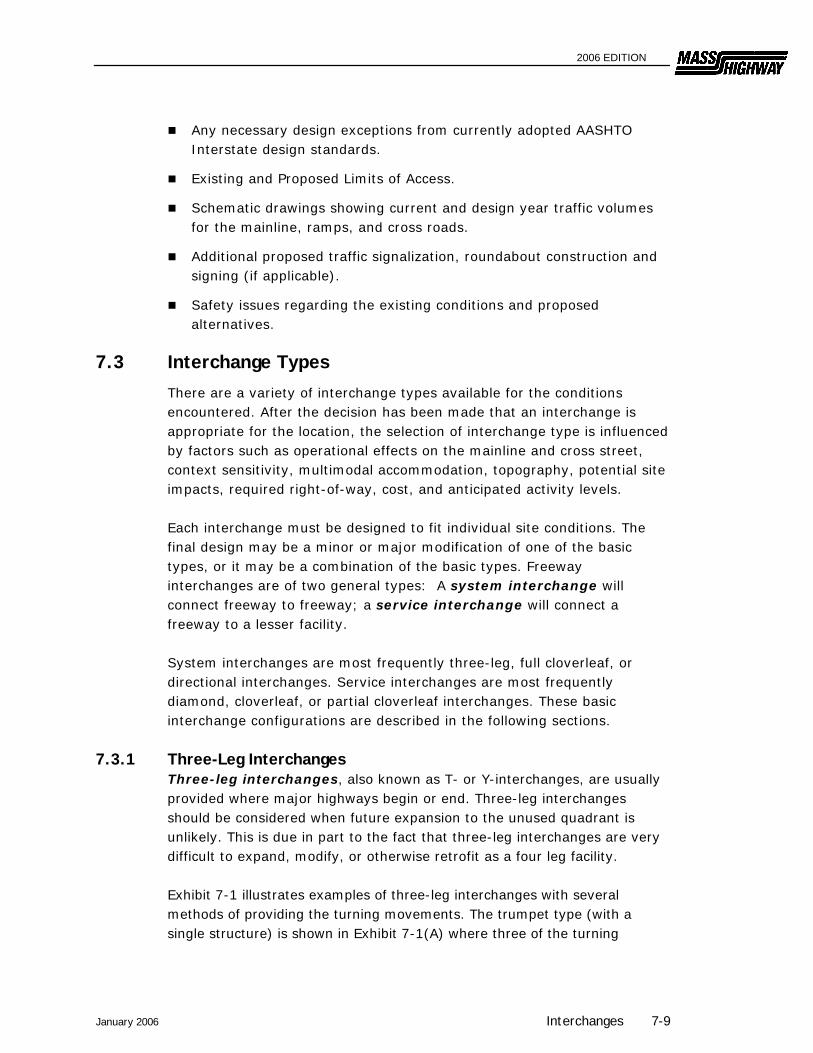
7.3.1 Three-Leg Interchanges Three-leg interchanges, also known as T- or Y-interchanges, are usually provided where major highways begin or end. Three-leg interchanges should be considered when future expansion to the unused quadrant is unlikely. This is due in part to the fact that three-leg interchanges are very difficult to expand, modify, or otherwise retrofit as a four leg facility. Exhibit 7-1 illustrates examples of three-leg interchanges with several methods of providing the turning movements. The trumpet type (with a single structure) is shown in Exhibit 7-1(A) where three of the turning
January 2006 Interchanges 7-9
2006 EDITION
movements are accommodated with direct or semi-direct ramps and one movement by a loop ramp. In general, the semi-direct ramp should favor the heavier left-turn movement and the loop the lighter volume. Where both left-turning movements are fairly heavy, the design of a directional T-type interchange shown in Exhibit 7-1(B) is best-suited. A fully directional interchange shown in Exhibit 7-1(C) is appropriate when all turning volumes are heavy or the intersection is between two access controlled highways. Construction of the configurations in Exhibit 7-1(B) and Exhibit 7-1(C) would be the most costly types because of the multiple structures required in the center of the interchange to accommodate three levels of traffic. For further examples and design considerations of additional T- and Y-interchanges, see AASHTO’s A Policy on Geometric Design of Highways and Streets.
Exhibit 7-1 Three-leg Interchanges
Source: A Policy on Geometric Design of Highways and Streets, AASHTO, 2004. Chapter 10 Grade Separations and Interchanges
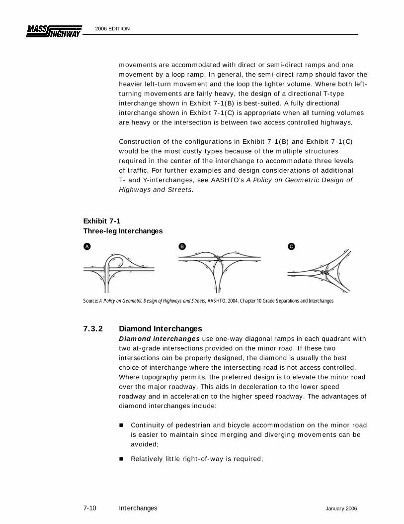
7.3.2 Diamond Interchanges Diamond interchanges use one-way diagonal ramps in each quadrant with two at-grade intersections provided on the minor road. If these two intersections can be properly designed, the diamond is usually the best choice of interchange where the intersecting road is not access controlled. Where topography permits, the preferred design is to elevate the minor road over the major roadway. This aids in deceleration to the lower speed roadway and in acceleration to the higher speed roadway. The advantages of diamond interchanges include:
Continuity of pedestrian and bicycle accommodation on the minor road is easier to maintain since merging and diverging movements can be avoided;
Relatively little right-of-way is required;
7-10 Interchanges January 2006
2006 EDITION
The configuration allows modifications to provide greater ramp capacity, if needed in the future;
Their common usage has resulted in a high degree of driver familiarity;
All traffic can enter and exit the freeway mainline at relatively high speeds and all exits from the freeway mainline are made before reaching the structure;
Adequate sight distance can usually be provided and the traffic maneuvers are normally uncomplicated;
Left-turning maneuvers require little extra travel distance relative to the partial cloverleaf.
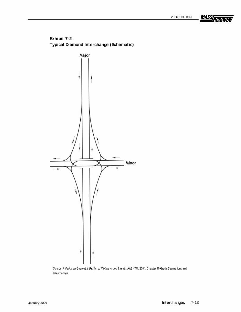
The primary disadvantages of a diamond interchange are potential operational problems with the two closely-spaced intersections on the minor road, and the potential for wrong-way entry onto the ramps. For this reason, a median is often provided on the cross road to facilitate proper channelization. Additional signing is also recommended to help prevent improper use of the ramps. Exhibit 7-2 illustrates a schematic of a typical diamond interchange.
7.3.2.1 Compressed Diamond Interchanges Compressed diamond interchanges are diamond interchanges where the nearest ramp terminal is less than 200 feet from the bridge. These interchanges are often used where right of way is restricted. Adequate sight distance based on unsignalized intersection criteria must be provided even if signals are installed. See Chapter 3 for further discussion of intersection sight distance. For further examples of design considerations, see AASHTO’s A Policy on Geometric Design of Highways and Streets.
7.3.2.2 Single Point Urban Interchange (SPUI) The SPUI interchange (also known as an urban interchange or single-point diamond interchange) consolidates left-turn movements to and from entrance and exit ramps at a single intersection as illustrated in Exhibit 7-3. The primary features of a SPUI are that all four left-turning moves are controlled by a single multi-phase traffic signal system and opposing left turns operate to the left of each other. These features can allow the SPUI to significantly increase the interchange capacity. The advantages of a SPUI include:
Vehicles making opposing left turns pass to the left of each other rather than to the right, so their paths do not intersect. In addition, the right-turn movements are typically free-flow movements and only the left turns must pass through the signalized intersection. This operation eliminates a major source of traffic conflict, thereby
January 2006 Interchanges 7-11
2006 EDITION
increasing overall intersection efficiency and reducing the traffic signal need to a three-phase operation rather than a four-phase typical of a compressed diamond interchange.
Since the SPUI has only one intersection, as opposed to two intersections in a conventional diamond interchanges, the operation of a single traffic signal on the crossroad may result in reduced delay through the intersection area.
Curve radii for left-turn movements through the intersection are significantly flatter than at conventional intersections, and, therefore, the left turns move at a higher speed and discharge more efficiently.
The configuration can help to reduce left-turning lane storage problems for drivers trying to enter the freeway.
U-turns can be easily provided for the major roadway within the ramp system.
The primary disadvantages are its higher costs because of the need for a larger structure, the need for a careful design of channelization to minimize driver confusion and the likelihood of wrong-way maneuvers, and the need for careful design of signal timing to accommodate pedestrians and bicyclists. Also, SPUIs built with a skewed angle between two roadways increase clear distances and adversely affect sight distance. Bicycle accommodation must consider signal timing for slower cyclists. Pedestrian crossing of the cross street at ramp terminals typically adds a signal phase, resulting in reduced operational efficiency for motor vehicles. Special consideration should be given to the location and alignment of cross walks to ensure adequate sight distance, minimize the length of the crossing, maximize vehicular storage lengths, and to coincide with driver expectations. For further discussion, examples and design considerations see A Policy on Geometric Design of Highways and Streets, AASHTO.
7-12 Interchanges January 2006
2006 EDITION
January 2006 Interchanges 7-13
Exhibit 7-2 Typical Diamond Interchange (Schematic)
Source: A Policy on Geometric Design of Highways and Streets, AASHTO, 2004. Chapter 10 Grade Separations and Interchanges

2006 EDITION
Exhibit 7-3 Single Point Urban Interchange
Source: A Policy on Geometric Design of Highways and Streets, AASHTO, 2004. Chapter 10 Grade Separations and Interchanges
7.3.3 Cloverleafs Cloverleaf interchanges are used at four-leg intersections and combine the use of one-way diagonal ramps with loop ramps to accommodate left-turn movements. Interchanges with loops in all four quadrants are referred to as full cloverleafs and all others are referred to as partial cloverleafs. Where two access controlled highways intersect, a full cloverleaf is the minimum type design interchange that provides connectivity for all movements between the highways. However, these interchanges introduce several undesirable operational features such as double exits
7-14 Interchanges January 2006

2006 EDITION
January 2006 Interchanges 7-15
and entrances from the mainline, weaving between entering and exiting vehicles, lengthy travel time and distance for left-turning vehicles, and large amounts of required right-of-way. Therefore, at system interchanges, a collector-distributor (C-D) road is often used to remove the weave from the mainline traffic. Exhibit 7-4 provides typical examples of full cloverleafs with and without C-D roads.
Exhibit 7-4 Full Cloverleafs
Source: A Policy on Geometric Design of Highways and Streets, AASHTO, 2004. Chapter 10 Grade Separations and Interchanges Partial cloverleafs are often used where right-of-way, multi-modal, and/or environmental restrictions preclude ramps in one or more quadrants. Exhibit 7-5 illustrates six examples of partial cloverleafs. In "A" and "B," both left-turn movements onto the major road are provided by loops, which is desirable. The other examples (C-F) illustrate two loops in opposite quadrants and loops in three quadrants. In these examples, the desirable feature is that no left-turn movements are made onto the major road. Partial cloverleaf arrangements are generally used when an obstruction prevents construction of ramps in one or more quadrants, or to provide connections for all movements without intersection delays (other than those associated with merging and weaving at a full-cloverleaf interchange). For freeway connections with other arterials, collectors and local roads, diamond interchanges are often preferred as discussed in Section 7.4.1.

2006 EDITION
Exhibit 7-5 Partial Cloverleaf Arrangements
Source: A Policy on Geometric Design of Highways and Streets, AASHTO, 2004. Chapter 10 Grade Separations and Interchanges
7-16 Interchanges January 2006
2006 EDITION
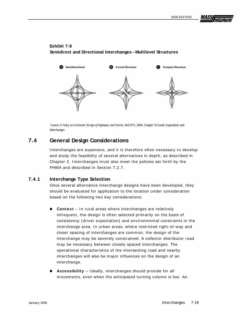
7.3.4 Directional and Semi-Directional Direct and semi-direct connections are used for important turning movements to reduce travel distance, increase speed and capacity, eliminate weaving, and to avoid the need for out-of-direction travel in driving on a loop. Higher levels of service can be realized on direct connections and, in some instances, on semi-direct ramps because of relatively high speeds and the likelihood of better terminal design. The following definitions apply to directional and semi-directional interchanges:
Direct Ramp Connection – A ramp that does not deviate greatly from the intended direction of travel (as does a loop, for example).
Semi-Direct Ramp Connection – A ramp that is indirect in alignment yet more direct than loops.
Directional Interchange – An interchange where one or more left-turning movements are provided by direct connection, even if the minor left-turn movements are accommodated on loops.
Semi-Directional Interchange – An interchange where one or more left-turning movements are provided by semi-direct connections, even if the minor left-turn movements are accommodated on loops.
Fully Directional Interchange – An interchange where all left-turning movements are provided by direct connections. Fully directional interchanges are generally preferred where two high-volume freeways intersect. While fully directional interchanges can be costly to construct due to an increased number of bridge crossings, they offer high capacity movements for both through and turning traffic with comparatively little additional area needed for construction.
Direct or semi-direct connections are used for heavy left-turn movements to reduce travel distance, increase speed and capacity, and eliminate weaving. Examples of direct and semi-direct interchanges are shown in Exhibits 7-6, 7-7 and 7-8. For further variations and examples of interchange types and related design considerations see AASHTO’s A Policy on Geometric Design of Highways and Streets.
January 2006 Interchanges 7-17

2006 EDITION
Exhibit 7-6 Semidirect Interchanges with Weaving
Note: Weaving adjacent to the through lanes is eliminated by providing collector-distributor roads as shown by dotted lines.
Source: A Policy on Geometric Design of Highways and Streets, AASHTO, 2004. Chapter 10 Grade Separations and Interchanges
Exhibit 7-7 Semidirect Interchanges without Weaving
Source: A Policy on Geometric Design of Highways and Streets, AASHTO, 2004. Chapter 10 Grade Separations and Interchanges
7-18 Interchanges January 2006
2006 EDITION
Exhibit 7-8 Semidirect and Directional Interchanges – Multilevel Structures
Source: A Policy on Geometric Design of Highways and Streets, AASHTO, 2004. Chapter 10 Grade Separations and Interchanges
7.4 General Design Considerations
Interchanges are expensive, and it is therefore often necessary to develop and study the feasibility of several alternatives in depth, as described in Chapter 2. Interchanges must also meet the policies set forth by the FHWA and described in Section 7.2.7.
7.4.1 Interchange Type Selection Once several alternative interchange designs have been developed, they should be evaluated for application to the location under consideration based on the following two key considerations:
Context – In rural areas where interchanges are relatively infrequent, the design is often selected primarily on the basis of consistency (driver expectation) and environmental constraints in the interchange area. In urban areas, where restricted right-of-way and closer spacing of interchanges are common, the design of the interchange may be severely constrained. A collector distributor road may be necessary between closely spaced interchanges. The operational characteristics of the intersecting road and nearby interchanges will also be major influences on the design of an interchange.
Accessibility – Ideally, interchanges should provide for all movements, even when the anticipated turning volume is low. An
January 2006 Interchanges 7-19

2006 EDITION
omitted maneuver causes confusion to those drivers searching for the exit or entrance. Particular attention to signing must be made to minimize confusion. In addition, unanticipated future developments may increase the demand for a given maneuver. Even when all ramps are not constructed sufficient right-of-way should be acquired for completing the interchange at a later date.
Additionally, interchange design should account for the following transportation system considerations:
Compatibility with the surrounding highway system;
Road user impacts (safety, travel distance and time, convenience and comfort for all users including pedestrians and bicyclists);
Right-of-way impacts and availability;
Uniformity of exit and entrance patterns;
Operational characteristics (single versus double exits, weaving, signing); and
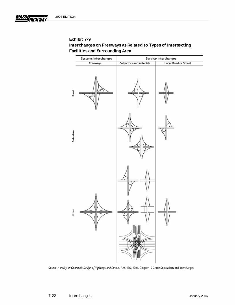
Construction and maintenance costs. Exhibit 7-9 depicts typical interchange configurations related to classifications of intersecting facilities in rural, suburban, and urban environments. For system interchanges, directional and semi-directional interchanges are preferred to cloverleaf designs from a user safety and operational efficiency perspective. However, many existing freeways were previously constructed using cloverleaf interchange configurations and projects to modify these existing interchanges are common. At service interchanges, the choice of interchange is usually between a diamond and cloverleaf configuration. The following should be considered when making the selection:
Unlike diamond interchanges and partial cloverleafs, full cloverleafs do not employ 90-degree intersections. Pedestrian and bicycle movements along cross streets are more difficult to accommodate safely at full cloverleaf interchanges than at partial cloverleaf or diamond interchanges because vehicular movements are usually free-flow.
7-20 Interchanges January 2006

2006 EDITION
All freeway exit maneuvers at diamond interchanges are executed before reaching the structure, conforming to driver expectations. Diamond interchanges also eliminate weaving on the freeway mainline and cross street. Some partial cloverleaf options can also provide these advantages.
Partial cloverleafs may be suitable for locations where construction of ramps in one or more quadrants of the interchange is infeasible or undesirable. Partial cloverleafs with loops in opposite quadrants are very desirable because they eliminate the weaving problem associated with full cloverleaf designs.
The double exit/entrance at cloverleafs can result in signing problems and driver confusion. Collector-distributor roads are often recommended to address signage problems and to reduce weaving on the freeway mainline.
Ramps at diamond interchanges can be widened to increase storage capacity. Loop ramps, regardless of width, almost always operate as a single lane, thereby limiting storage capacity. Operational capacity needs to consider the control at the ramp terminal and may not always be significantly greater than with free-flow loops.
The loops in cloverleafs result in a greater travel distance for left-turning vehicles than do diamonds. Loops operate at lower speeds, especially for trucks, which have the potential to turn over if traveling the loop too fast.
Cloverleafs require more right-of-way and are more expensive to construct than diamonds.
Full cloverleafs provide higher capacity than most diamond configurations since movements at the ramp terminals are usually free-flow and subject only to weaving and merging delays rather intersection control delay.
Full cloverleaf interchanges are often considered more appropriate than diamonds when traffic volumes are high. However, when compared with the advantages of diamonds in terms of pedestrian and bicycle accommodation, right-of-way requirements, and driver expectations, the designer should investigate measures to increase the capacity of diamond interchanges such as advanced signal phasing, signal coordination on the minor road, roundabout intersections, or SPUI interchanges before selecting a cloverleaf design.
January 2006 Interchanges 7-21
2006 EDITION
Exhibit 7-9 Interchanges on Freeways as Related to Types of Intersecting Facilities and Surrounding Area
Source: A Policy on Geometric Design of Highways and Streets, AASHTO, 2004. Chapter 10 Grade Separations and Interchanges
7-22 Interchanges January 2006
2006 EDITION
7.4.2 Capacity and Level of Service An interchange must be designed to accommodate the anticipated activity levels for the design year (see Chapter 3 for details). The capacity and level of service for an interchange will depend upon the operation of its individual elements along with the interaction and coordination of each of these elements in the overall design. The individual elements are as follows:
Basic freeway section where interchanges are not present;
Freeway/ramp junctions or terminals (Section 7.7);
Weaving areas (Section 7.6.3);
Ramps (Section 7.7); and
Ramp/minor road intersections (Section 7.8). For most situations, the capacity and level of service at interchanges is focused on motor vehicles since interchanges are most often used at freeway connection points. The basic reference for level of service measures for interchanges is the Highway Capacity Manual. It is desirable for the level of service of each interchange element to be at least that provided on the basic freeway section. In addition, the designer should ensure that the operation of the ramp/minor road intersection will not impair the operation of the mainline. This will likely involve a consideration of the operational characteristics on the minor road for some distance in either direction from the interchange.
7.4.3 Safety Considerations Typical design challenges at interchanges include:
Sight Distance at Exit Points — Sight distance is often determined with respect to the gore, which is the area where a ramp diverges from the mainline. When feasible, decision sight distance should be provided to enable drivers approaching freeway exits to see the pavement surface from the painted gore nose to the limit of the paved gore. Proper advance signing of exits is also essential and additional signing is required when it is not possible to obtain the decision sight distance.
January 2006 Interchanges 7-23
2006 EDITION
Exit Speed Changes — The design should provide enough distance to allow safe deceleration from the freeway design speed to the design speed of the first exit curve.
Merges — The most frequent crash-type at interchanges is the rear-end collision at entrances onto the freeway. This problem can be reduced by providing an acceleration lane of sufficient length with adequate sight distance to allow a merging vehicle to attain speed and find a sufficient gap into which to merge.
Left-Side Entrances and Exits — Left-side entrances and exits should be avoided as they are contrary to driver expectations and have been associated with higher crash rates.
Fixed-Object Hazards — A number of fixed objects may be located within interchanges, such as signs at exit gores or bridge piers and rails. These should be removed where possible, placed outside of the recovery area where possible, made breakaway, or shielded with barriers or impact attenuators.
Wrong-Way Entrances — In almost all cases, wrong-way maneuvers originate at interchanges. Some cannot be avoided, but others may result from driver confusion due to poor visibility, deceptive ramp arrangement, or inadequate signing. The interchange design must attempt to minimize wrong-way possibilities. This includes staggering ramp terminals and controlling access in the vicinity of the ramps.
Excessive Speed on Minor Roadways — Ramp and merge designs should slow down drivers leaving the high-speed roadway so that they will not exceed the design speed on the secondary road. The section of the secondary road in the interchange area should have a design speed similar to (not faster than) the design of adjoining sections of that road.
7.5 Traffic Lane Principles
A variety of traffic lane principles are important in the design of an interchange. The application of these principles will help to minimize confusion, operational problems, and the number of crashes.
7.5.1 Basic Number of Lanes and Freeway Lane Drops The basic number of lanes is the minimum number of lanes needed over a significant length of a highway based on the overall capacity needs of that section. The number of lanes should remain constant over short distances. For example, a lane should not be dropped at the
7-24 Interchanges January 2006
2006 EDITION
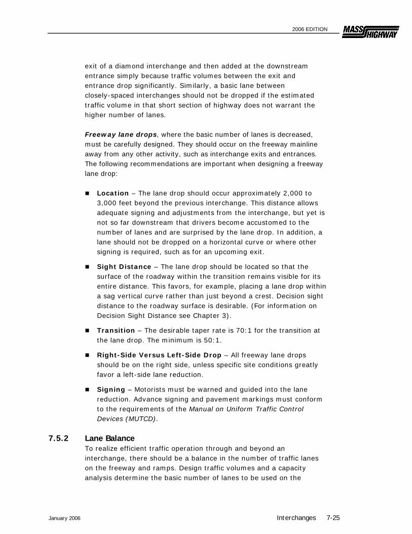
exit of a diamond interchange and then added at the downstream entrance simply because traffic volumes between the exit and entrance drop significantly. Similarly, a basic lane between closely-spaced interchanges should not be dropped if the estimated traffic volume in that short section of highway does not warrant the higher number of lanes. Freeway lane drops, where the basic number of lanes is decreased, must be carefully designed. They should occur on the freeway mainline away from any other activity, such as interchange exits and entrances. The following recommendations are important when designing a freeway lane drop:
Location – The lane drop should occur approximately 2,000 to 3,000 feet beyond the previous interchange. This distance allows adequate signing and adjustments from the interchange, but yet is not so far downstream that drivers become accustomed to the number of lanes and are surprised by the lane drop. In addition, a lane should not be dropped on a horizontal curve or where other signing is required, such as for an upcoming exit.
Sight Distance – The lane drop should be located so that the surface of the roadway within the transition remains visible for its entire distance. This favors, for example, placing a lane drop within a sag vertical curve rather than just beyond a crest. Decision sight distance to the roadway surface is desirable. (For information on Decision Sight Distance see Chapter 3).
Transition – The desirable taper rate is 70:1 for the transition at the lane drop. The minimum is 50:1.
Right-Side Versus Left-Side Drop – All freeway lane drops should be on the right side, unless specific site conditions greatly favor a left-side lane reduction.
Signing – Motorists must be warned and guided into the lane reduction. Advance signing and pavement markings must conform to the requirements of the Manual on Uniform Traffic Control Devices (MUTCD).
7.5.2 Lane Balance To realize efficient traffic operation through and beyond an interchange, there should be a balance in the number of traffic lanes on the freeway and ramps. Design traffic volumes and a capacity analysis determine the basic number of lanes to be used on the
January 2006 Interchanges 7-25
2006 EDITION
highway and the minimum number of lanes on the ramps. After the basic number of lanes is determined for each roadway, the balance in the number of lanes should be checked on the basis of the following principles:
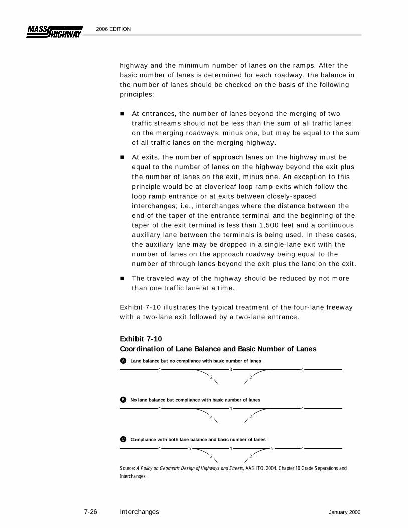
At entrances, the number of lanes beyond the merging of two traffic streams should not be less than the sum of all traffic lanes on the merging roadways, minus one, but may be equal to the sum of all traffic lanes on the merging highway.
At exits, the number of approach lanes on the highway must be equal to the number of lanes on the highway beyond the exit plus the number of lanes on the exit, minus one. An exception to this principle would be at cloverleaf loop ramp exits which follow the loop ramp entrance or at exits between closely-spaced interchanges; i.e., interchanges where the distance between the end of the taper of the entrance terminal and the beginning of the taper of the exit terminal is less than 1,500 feet and a continuous auxiliary lane between the terminals is being used. In these cases, the auxiliary lane may be dropped in a single-lane exit with the number of lanes on the approach roadway being equal to the number of through lanes beyond the exit plus the lane on the exit.
The traveled way of the highway should be reduced by not more than one traffic lane at a time.
Exhibit 7-10 illustrates the typical treatment of the four-lane freeway with a two-lane exit followed by a two-lane entrance.
Exhibit 7-10 Coordination of Lane Balance and Basic Number of Lanes
Source: A Policy on Geometric Design of Highways and Streets, AASHTO, 2004. Chapter 10 Grade Separations and Interchanges
7-26 Interchanges January 2006
2 2
44 3
Lane balance but no compliance with basic number of lanes
4
2
4
2
4
No lane balance but compliance with basic number of lanes
55 4
2
4
2
4
Compliance with both lane balance and basic number of lanes

2006 EDITION
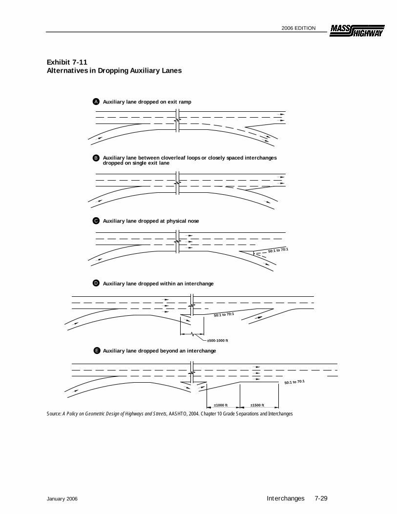
7.5.3 Auxiliary Lanes Variations in traffic demand over short distances should be accommodated by means of auxiliary lanes, where needed. An auxiliary lane is defined as the portion of the roadway adjoining the traveled way for speed change, turning, storage for turning, weaving, truck climbing, and other purposes supplementary to through-traffic movement. The width of an auxiliary lane should equal that of the through lanes. An auxiliary lane may be provided to comply with the concept of lane balance, to comply with capacity requirements in the case of adverse grades, or to accommodate speed changes, weaving, and maneuvering of entering and exiting traffic. Where auxiliary lanes are provided along freeway main lanes, the adjacent shoulder would desirably be 8 to 12 feet in width, with a minimum of 6 feet. Auxiliary lanes may be added to satisfy capacity and weaving requirements between interchanges, to accommodate traffic pattern variations at interchanges, and for simplification of operations (such as reducing lane changing). The principles of lane balance must always be applied in the use of auxiliary lanes. In this manner the necessary balance between traffic load and capacity is provided, and lane balance and needed operational flexibility are realized. Operational efficiency may be improved by using a continuous auxiliary lane between the entrance and exit terminals where interchanges are closely spaced, the distance between the end of the taper on the entrance terminal and the beginning of the taper on the exit terminal is short, and/or where local frontage roads do not exist. Where interchanges are closely spaced in urban areas, the acceleration lane from an entrance ramp should be extended to the deceleration lane of a downstream exit ramp. Exhibit 7-11 shows alternatives in dropping auxiliary lanes.
7.5.4 Distance Between Successive Ramp Terminals On freeways there are frequently two or more ramp terminals in close succession along the through lanes. To provide sufficient maneuvering length and adequate space for signing, a reasonable distance is required between terminals. Spacing between successive outer ramp terminals is dependent on the classification of the interchanges involved, the function of the ramp pairs (entrance (EN) or exit (EX)),
January 2006 Interchanges 7-27

2006 EDITION
and weaving potential, when applicable. The five possible ramp-pair combinations are:
entrance followed by entrance (EN-EN), exit followed by exit (EX-EX), exit followed by entrance (EX-EN), entrance followed by exit (EN-EX) (weaving), and turning roadways.
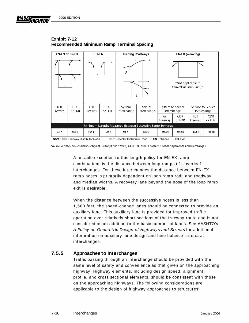
When an entrance ramp is followed by an exit ramp, the absolute minimum distance between the successive noses is governed by weaving consideration. Weaving sections are highway segments where the pattern of traffic entering and leaving at contiguous points of access results in vehicle paths crossing each other. (See Highway Capacity Manual for capacity of weaving sections and Chapter 2 of AASHTO’s A Policy on Geometric Design of Highways and Streets for weaving lengths and widths.) Exhibit 7-12 shows the minimum values for spacing of ramp terminals for the various ramp-pair combinations as they are applicable to the interchange classifications.
Distance between successive ramp terminals should be determined by the weaving lengths.
7-28 Interchanges January 2006
2006 EDITION
January 2006 Interchanges 7-29
Exhibit 7-11 Alternatives in Dropping Auxiliary Lanes
Source: A Policy on Geometric Design of Highways and Streets, AASHTO, 2004. Chapter 10 Grade Separations and Interchanges
Auxiliary lane dropped at physical nose
Auxiliary lane dropped beyond an interchange
±1500 ft±1000 ft
50:1 to 70:1
50:1 to 70:1
Auxiliary lane dropped on exit ramp
Auxiliary lane between cloverleaf loops or closely spaced interchanges dropped on single exit lane
±500-1000 ft
50:1 to 70:1
Auxiliary lane dropped within an interchange
2006 EDITION
Exhibit 7-12 Recommended Minimum Ramp Terminal Spacing
Source: A Policy on Geometric Design of Highways and Streets, AASHTO, 2004. Chapter 10 Grade Separations and Interchanges A notable exception to this length policy for EN-EX ramp combinations is the distance between loop ramps of cloverleaf interchanges. For these interchanges the distance between EN-EX ramp noses is primarily dependent on loop ramp radii and roadway and median widths. A recovery lane beyond the nose of the loop ramp exit is desirable. When the distance between the successive noses is less than 1,500 feet, the speed-change lanes should be connected to provide an auxiliary lane. This auxiliary lane is provided for improved traffic operation over relatively short sections of the freeway route and is not considered as an addition to the basic number of lanes. See AASHTO’s A Policy on Geometric Design of Highways and Streets for additional information on auxiliary lane design and lane balance criteria at interchanges.
7.5.5 Approaches to Interchanges Traffic passing through an interchange should be provided with the same level of safety and convenience as that given on the approaching highway. Highway elements, including design speed, alignment, profile, and cross sectional elements, should be consistent with those on the approaching highways. The following considerations are applicable to the design of highway approaches to structures:
EN-EN or EX-EX EX-EN Turning Roadways EN-EX (weaving)
Note: FDR Freeway Distributor Road CDR Collector Distributor Road EN Entrance EX Exit
L
L
L
L
7-30 Interchanges January 2006

2006 EDITION
Through interchange areas, changes in alignment and cross
sectional elements may be needed to ensure proper operation and to develop the capacity needed at the ramp terminals;
Pedestrian and bicycle accommodation, consistent with the remaining segments of the roadway, should be continued through interchange area;
Relatively sharp horizontal or vertical curves should be avoided;
Four-lane roadways should be divided through interchange areas.
7.6 Freeway/Ramp Junctions
As described in Section 7.5, there are two basic types of freeway/ramp junctions, exits and entrances (often encountered in this order when traveling on the freeway mainline).
7.6.1 Exit Ramps Exit ramps are one-way roadways which allow traffic to exit from the freeway and provide access to other crossing highways. The following design considerations are applicable to exit ramps.
7.6.1.1 Sight Distance Decision sight distance (see Chapter 3) should be provided for drivers approaching an exit. Sufficient sight distance is particularly important for exit loops immediately beyond a structure. Vertical curvature or bridge piers can obstruct the exit point if not carefully designed. When measuring for adequate sight distance, the designer should use the pavement surface at the gore nose as height of object.
7.6.1.2 Deceleration Lanes Sufficient deceleration distance is needed to allow an exiting vehicle to leave the freeway mainline safely and comfortably. All deceleration should occur within the full width of the deceleration lane. The length of the deceleration lane will depend upon the design speed of the mainline and the design speed of the first (or controlling) curve on the exit ramp. In addition, if compound curvature is used, there should be sufficient deceleration in advance of each successively sharper curve.
January 2006 Interchanges 7-31
2006 EDITION
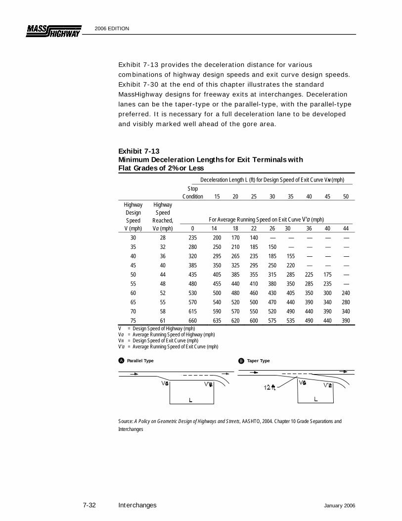
Exhibit 7-13 provides the deceleration distance for various combinations of highway design speeds and exit curve design speeds. Exhibit 7-30 at the end of this chapter illustrates the standard MassHighway designs for freeway exits at interchanges. Deceleration lanes can be the taper-type or the parallel-type, with the parallel-type preferred. It is necessary for a full deceleration lane to be developed and visibly marked well ahead of the gore area. Exhibit 7-13 Minimum Deceleration Lengths for Exit Terminals with Flat Grades of 2% or Less
Deceleration Length L (ft) for Design Speed of Exit Curve VN (mph) Stop
Condition
15
20
25
30
35
40
45
50 Highway Design Speed
Highway Speed
Reached, For Average Running Speed on Exit Curve V'a (mph) V (mph) Va (mph) 0 14 18 22 26 30 36 40 44
30 28 235 200 170 140 — — — — — 35 32 280 250 210 185 150 — — — — 40 36 320 295 265 235 185 155 — — — 45 40 385 350 325 295 250 220 — — — 50 44 435 405 385 355 315 285 225 175 — 55 48 480 455 440 410 380 350 285 235 — 60 52 530 500 480 460 430 405 350 300 240 65 55 570 540 520 500 470 440 390 340 280 70 58 615 590 570 550 520 490 440 390 340 75 61 660 635 620 600 575 535 490 440 390
V = Design Speed of Highway (mph) Va = Average Running Speed of Highway (mph) VN = Design Speed of Exit Curve (mph) V'a = Average Running Speed of Exit Curve (mph)
Source: A Policy on Geometric Design of Highways and Streets, AASHTO, 2004. Chapter 10 Grade Separations and Interchanges
Parallel Type Taper Type
7-32 Interchanges January 2006

2006 EDITION
Deceleration lanes are measured from the point where the lane reaches 12 feet wide to the painted nose for parallel-type and the first controlling curve for taper-type ramps. Greater distances should be provided if practical. If the deceleration lane is on a grade of 3% or more, the length of the lane should be adjusted according to the criteria in Exhibit 7-15.
7.6.1.3 Superelevation The superelevation at an exit ramp must be developed to transition the driver properly from the mainline to the curvature at the exit. The principles of superelevation for open highways, as discussed in Chapter 4, should be applied to the exit design with the following criteria applied:
The maximum superelevation rate in Massachusetts is 6.0 percent.
Preferably, full superelevation is achieved at the PCC at the gore nose. However, this is subject to the minimum longitudinal slopes described in Chapter 4.
The paved portion of the gore is normally sloped at 3.0%.
7.6.1.4 Gore Area The gore area is normally considered to be both the paved triangular area between the through lane and the exit lane and the unpaved graded area which extends downstream beyond the gore nose. The following should be considered when designing the gore:
Signing in advance of the exit and at the divergence should be in accordance with the Manual on Uniform Traffic Control Devices (MUTCD). This also applies to the pavement markings in the triangular area upstream from the gore nose.
If possible, the area beyond the gore nose should be free of signs and luminaire supports. If they must be present, they must be yielding or breakaway, or shielded by guardrail or impact attenuators.
The graded area beyond the gore nose should be as flat as possible. If the difference in elevation between the exit ramp or loop and the mainline increases rapidly, this may not be possible. These areas will likely be non-traversable and the gore design must shield these areas from the driver. Often, the vertical divergence of the ramp and mainline will warrant protection for both roadways beyond the gore.
January 2006 Interchanges 7-33
2006 EDITION
7.6.2 Entrance Ramps Entrance ramps are one-way roadways which allow traffic to enter a freeway. Design considerations for entrance ramps are described below.
7.6.2.1 Sight Distance Decision sight distance should be provided for drivers on the entrance ramp and on the mainline approaching an entrance terminal. Drivers on the mainline need sufficient distance to see the merging traffic so that they can adjust their speed or change lanes to allow the merging traffic to enter the freeway. Likewise, drivers on the entrance ramp need to see a sufficient distance upstream from the entrance to locate the gaps in the traffic stream within which to merge. When measuring decision sight distance for entrance ramps, use 3.5 feet as the height of eye and objects.
7.6.2.2 Acceleration Lanes A properly-designed acceleration lane will facilitate driver comfort, traffic operations, and safety. Exhibit 7-30 at the end of this chapter illustrates the MassHighway standard designs for entrance ramps. The length of the acceleration lane will primarily depend upon the design speed of the last (or controlling) curve on the entrance ramp and the design speed of the mainline. Exhibit 7-14 provides the data for minimum lengths of acceleration lanes. These lengths are for the full width of the acceleration lane, and are measured from the end of the painted nose for parallel-type, and from the end of the last controlling curve on taper-type ramp junctions, to a point where the full 12-foot lane width terminates. Taper lengths, typically 300 feet, are in addition to the acceleration lane lengths. If the acceleration lane is on a grade of 3% or more, the length of the lane should be adjusted according to the criteria in Exhibit 7-15. The values in Exhibit 7-14 provide sufficient distance for vehicle acceleration; however, they may not safely allow a vehicle to merge into the mainline if traffic volumes are high. Where the mainline and ramp will carry traffic volumes approaching the design capacity of the merging area, the acceleration lane length should be extended by 200 feet or more.
7-34 Interchanges January 2006

2006 EDITION
January 2006 Interchanges 7-35
Exhibit 7-14 Minimum Acceleration Lengths for Entrance Terminals with Flat Grades of 2% or Less
Acceleration Length L (ft) for Entrance Curve Design Speed (mph) Stop
Condition
15
20
25
30
35
40
45
50 Highway Design Speed
Highway Speed
Reached, and Initial Speed V'a (mph) V (mph) Va (mph) 0 14 18 22 26 30 36 40 44
30 28 180 140 — — — — — — —
35 32 280 220 160 — — — — — —
40 36 360 300 270 210 120 — — — —
45 40 560 490 440 380 280 160 — — —
50 44 720 660 610 550 450 350 130 — —
55 48 960 900 810 780 670 550 320 150 —
60 52 1200 1140 1100 1020 910 800 550 420 180
65 55 1410 1350 1310 1220 1120 1000 770 600 370
70 58 1620 1560 1520 1420 1350 1230 1000 820 580
75 61 1790 1730 1630 1580 1510 1420 1160 1040 780 Note: Uniform 50:1 to 70:1 tapers are recommended where lengths of acceleration lanes exceed 1,300 feet.
Source: A Policy on Geometric Design of Highways and Streets, AASHTO, 2004. Chapter 10 Grade Separations and Interchanges

2006 EDITION
Exhibit 7-15 Speed Change Lane Adjustment Factors as a Function of Grade
Deceleration Lanes — Ratio of Length on Grade to
Length on Level for Design Speed of Turning Curve (mph) Design Speed of Highway (mph)
All Exit Curve Design Speeds
All Speeds 3 to 4% Upgrade = 0.9 3 to 4% Downgrade = 1.2 5 to 6% Upgrade = 0.8 5 to 6% Downgrade = 1.35
Acceleration Lanes — Ratio of Length on Grade to
Length on Level for Design Speed of Turning Curve (mph) Design Speed of Highway (mph) 20 30 40 50 All Speeds 3 to 4% Upgrade 3 to 4% Downgrade
40 1.3 1.3 — — 0.7 45 1.3 1.35 — — 0.675 50 1.3 1.4 1.4 — 0.65 55 1.35 1.45 1.45 — 0.625 60 1.4 1.5 1.5 1.6 0.6 65 1.45 1.55 1.6 1.7 0.6 70 1.5 1.6 1.7 1.8 0.6 5 to 6% Upgrade 5 to 6% Downgrade
40 1.5 1.5 — — 0.6 45 1.5 1.6 — — 0.575 50 1.5 1.7 1.9 — 0.55 55 1.6 1.8 2.05 — 0.525 60 1.7 1.9 2.2 2.5 0.5 65 1.85 2.05 2.4 2.75 0.5 70 2.0 2.2 2.6 3.0 0.5
Note: Ratio from this table multiplied by the length in Exhibit 7-13 or 7-14 gives length of speed change lane on grade. Source: A Policy on Geometric Design of Highways and Streets, AASHTO, 2004. Chapter 10 Grade Separations and Interchanges
7.6.2.3 Superelevation Ramp superelevation should be gradually transitioned to meet the normal cross slope of the mainline. The principles of superelevation for open highways, as discussed in Chapter 4, should be applied to the entrance design with the following criteria applied:
The maximum superelevation rate in Massachusetts is 6.0 percent.
7-36 Interchanges January 2006
2006 EDITION
January 2006 Interchanges 7-37
Preferably, the cross slope of the acceleration lane will equal the cross slope of the adjacent through lane at the PT of the flat horizontal curve near the entrance gore.
The superelevation transition should not exceed the minimum longitudinal slopes provided in Chapter 4.
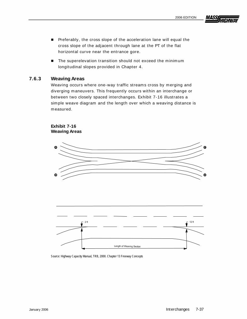
7.6.3 Weaving Areas Weaving occurs where one-way traffic streams cross by merging and diverging maneuvers. This frequently occurs within an interchange or between two closely spaced interchanges. Exhibit 7-16 illustrates a simple weave diagram and the length over which a weaving distance is measured. Exhibit 7-16 Weaving Areas
Source: Highway Capacity Manual, TRB, 2000. Chapter 13 Freeway Concepts
2006 EDITION
The capacity and level of service calculations are made from the methodology presented in the Highway Capacity Manual. The methodology determines the needed length on the weaving section to accommodate the predicted traffic conditions, including the weaving and non-weaving volumes and the average running speed of those volumes. Important elements to be considered in this analysis are as follows:
The number of lanes in the weaving areas;
The configuration of the section in terms of lane balance (i.e., the adding and dropping of auxiliary lanes);
The level of service (preferably, it will be the same as the mainline; it should not be more than one level below the mainline); and
The speed of weaving vehicles should be within 5 mph of non-weaving vehicles to provide acceptable operation.
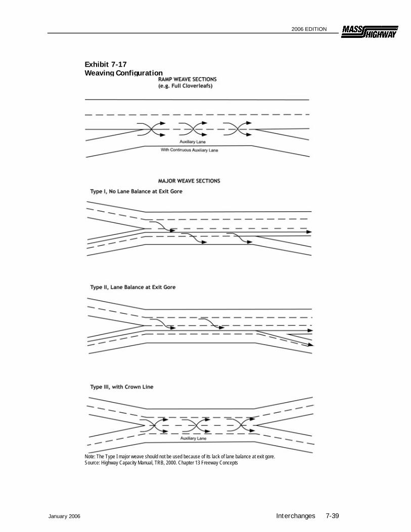
Exhibit 7-17 illustrates a ramp-weave section and three major-weave sections. The ramp weave section occurs in cloverleaf interchanges where a freeway entrance from an inner loop is immediately followed by an exit onto an inner loop. The entrance and exit are joined by a continuous auxiliary lane. This weaving configuration is complicated because all weaving vehicles are involved in a ramp movement which usually requires reduced speeds due to restrictive geometry. Therefore, three vehicle operations are occurring simultaneously — weaving, acceleration, and deceleration. The methodology in the Highway Capacity Manual should be used to determine the needed length for this section. Exhibit 7-30 at the end of this chapter illustrates the design details for the interior of a clover leaf interchange and provides the minimum distance between the entrance and exit loops within the interchange area. If the weave area is on a freeway, or if the site conditions will not allow the necessary distance, a collector-distributor road should be provided. Major-weave sections differ from the ramp-weave in that multiple lanes are involved and the geometry allows weaving speeds approximately equal to the speed on the open freeway. The Type 1 weave shown in Exhibit 7-17 is undesirable because of the lack of lane balance. The Highway Capacity Manual provides the methodologies for computing the length, capacity and level of service for weaving sections. Regardless of the calculations from the Highway Capacity Manual, the minimum desirable length of major-weave section is 1,100 feet.
7-38 Interchanges January 2006
2006 EDITION
January 2006 Interchanges 7-39
Exhibit 7-17 Weaving Configuration
Note: The Type I major weave should not be used because of its lack of lane balance at exit gore. Source: Highway Capacity Manual, TRB, 2000. Chapter 13 Freeway Concepts
2006 EDITION
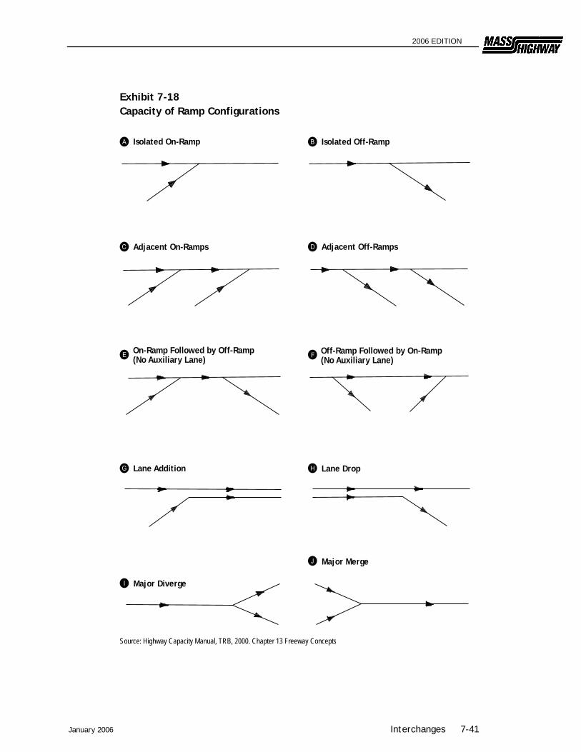
7.6.4 Capacity and Level of Service The capacity and level of service for freeway exits and entrances should be computed using the procedures in the Highway Capacity Manual. Those factors which will affect the calculations of traffic operation conditions at freeway/ramp junctions are:
Acceleration and deceleration distances; Number of lanes; Type of terrain or grade conditions; Merge and diverge volumes; and Freeway volumes.
The methodology in the Highway Capacity Manual will allow the analysis of isolated ramps or of ramps in association with another ramp upstream or downstream. Exhibit 7-18 illustrates several of the configurations which can be analyzed using the Highway Capacity Manual procedures. Exhibit 7-18 shows volumes which can be accommodated at a ramp junction for a given level of service.
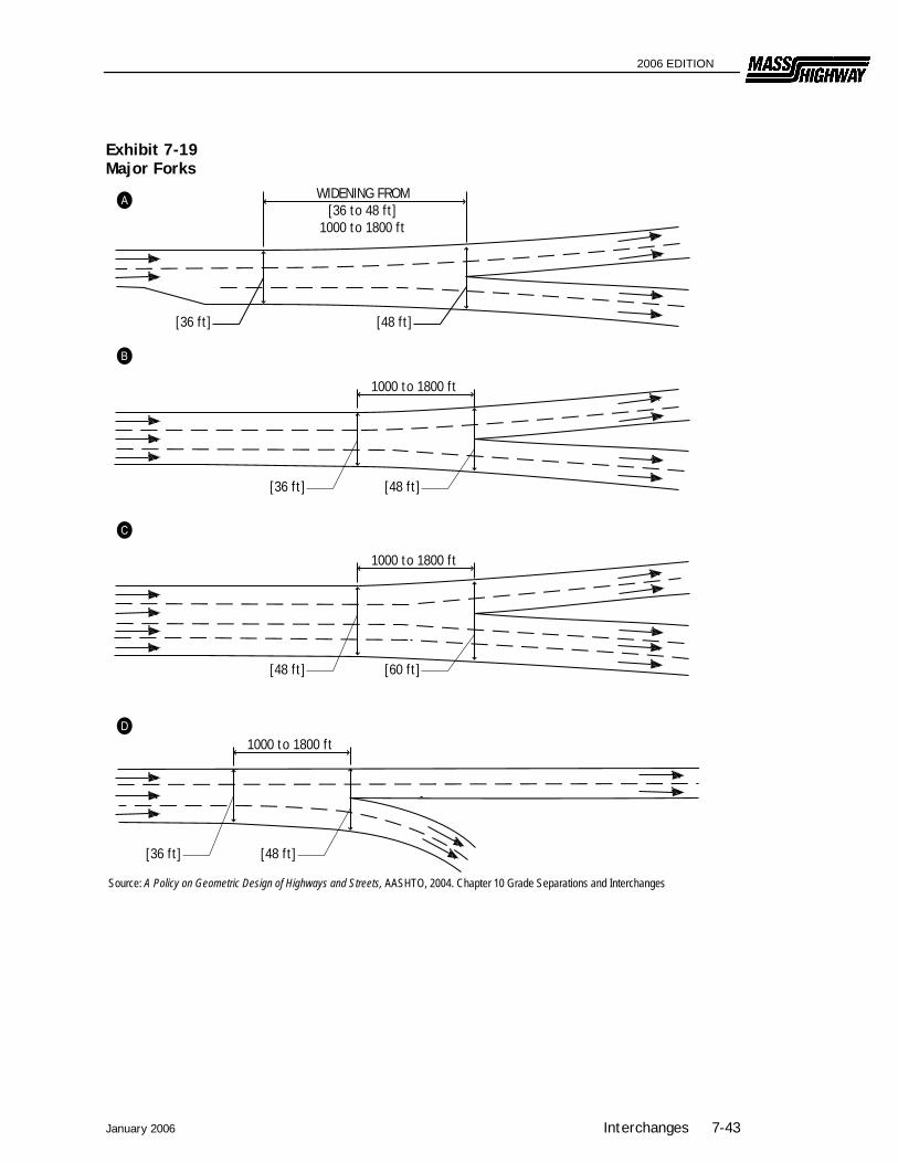
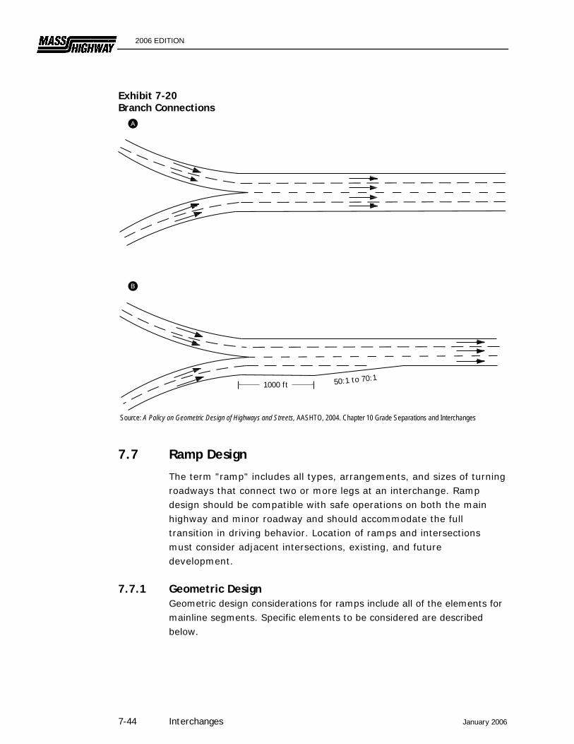
7.6.5 Major Forks and Branch Connections Major forks are where a freeway separates into two distinct freeways. The design of major forks is subject to the same principles of lane balance as any other diverging area. The total number of lanes in the two roadways beyond the divergence should exceed the number of lanes approaching the diverging area by at least one. Exhibit 7-19 illustrates three schematics for a major fork. It is important that one interior lane has an option to go in either direction. This interior lane should be widened over a distance of about 1,000 to 1,800 feet. Branch connections are where two freeways converge into one freeway. Exhibit 7-20 illustrates two schematics for a branch connection. When a lane is dropped, as in "B," this should be designed as a freeway lane drop (see Exhibit 7-11) from the outside, not through merging interior lanes.
7-40 Interchanges January 2006
2006 EDITION
January 2006 Interchanges 7-41
Exhibit 7-18 Capacity of Ramp Configurations
Source: Highway Capacity Manual, TRB, 2000. Chapter 13 Freeway Concepts
Isolated Off-RampIsolated On-Ramp
Adjacent On-Ramps Adjacent Off-Ramps
On-Ramp Followed by Off-Ramp (No Auxiliary Lane)
Off-Ramp Followed by On-Ramp (No Auxiliary Lane)
Lane Addition Lane Drop
Major Diverge
Major Merge

2006 EDITION
Exhibit 7-18 Capacity of Ramp Configurations (Continued) Level-of-Service Criteria for Checkpoint Flow Rates at Ramp-Freeway Terminals
Freeway Flow Rates (PCPH) (c)
Level of
Merge Flow Rate
(PCPH)
Diverge Flow Rate
(PCPH) 70 mph
Design Speed 60 mph
Design Speed 50 mph
Design Speed Vm(a) Vd(b)Service 4-lane 6-lane 8-lane 4-lane 6-lane 8-lane 4-lane 6-lane 8-lane
A <600 <650 <1,400 <2,100 <2,800 (d) (d) (d) (d) (d) (d)
B <1,000 <1,050 <2,200 <3,300 <4,400 <2,000 <3,000 <4,000 (d) (d) (d)
C <1,450 <1,500 <3,100 <4,650 <6,200 <2,800 <4,200 <5,600 <2,600 <3,900 <5,200 D <1,750 <1,800 <3,700 <5,550 <7,400 <3,400 <5,100 <6,800 <3,200 <4,800 <6,400 E <2,000 <2,000 <4,000 <6,000 <8,000 <4,000 <6,000 <8,000 <3,800 <5,700 <7,600 F — Widely Variable —
(a) Lane 1 flow rate plus ramp flow rate for one-lane, right-side on ramps. (b) Lane 1 flow rate immediately upstream of off-ramp for one-lane, right-side ramps. (c) Total freeway flow rate in one direction upstream of off-ramp and/or downstream of on-ramp. (d) Level of service not attainable due to design speed restrictions. Source: Adapted from Highway Capacity Manual, TRB, 2000. Chapter 13 Freeway Concepts
7-42 Interchanges January 2006
2006 EDITION
January 2006 Interchanges 7-43
Exhibit 7-19 Major Forks
Source: A Policy on Geometric Design of Highways and Streets, AASHTO, 2004. Chapter 10 Grade Separations and Interchanges
WIDENING FROM [36 to 48 ft]
1000 to 1800 ft
1000 to 1800 ft
[36 ft] [48 ft]
[36 ft] [48 ft]
1000 to 1800 ft
[48 ft] [60 ft]
1000 to 1800 ft
[36 ft] [48 ft]
2006 EDITION
Exhibit 7-20 Branch Connections
Source: A Policy on Geometric Design of Highways and Streets, AASHTO, 2004. Chapter 10 Grade Separations and Interchanges
7.7 Ramp Design
The term "ramp" includes all types, arrangements, and sizes of turning roadways that connect two or more legs at an interchange. Ramp design should be compatible with safe operations on both the main highway and minor roadway and should accommodate the full transition in driving behavior. Location of ramps and intersections must consider adjacent intersections, existing, and future development.
7.7.1 Geometric Design Geometric design considerations for ramps include all of the elements for mainline segments. Specific elements to be considered are described below.
1000 ft 50:1 to 70:1
7-44 Interchanges January 2006

2006 EDITION
7.7.1.1 Design Speed Ideally, the ramp design speeds should approximate the low-volume operating speed on the intersecting highways. Where this is not practical, the values in Exhibit 7-21 should be used as the minimum design speed. These design speeds apply to the ramp proper and not to the freeway/ramp junction. If the two intersecting mainlines have different design speeds, the higher of the two should control in selecting the design speed for the ramp as a whole. However the design speed should vary along the ramp, with the portion of the ramp nearer the lower speed highway being designed for the lower speed. In general, the higher range of design speeds should apply to diagonal ramps for right turns, such as at diamond and cloverleaf interchanges. The low end of the range should apply to loop ramps. Loop ramps with design speeds above 30 miles/hour require extremely large areas and greatly increase the travel distance for vehicles. If a ramp will be terminating at an at-grade intersection with stop or signal control, the design speeds in Exhibit 7-21 will not apply to the ramp portion near the intersection.
Exhibit 7-21 Guide Values For Design Speed based on Highway Design Speed
Highway Design Speed (mph) 30 35 40 45 50 55 60 65 70 75
Ramp Design Speed (mph)
Upper Range (85%) 25 30 35 40 45 48 50 55 60 65
Middle Range (70%) 20 25 30 33 35 40 45 45 50 55
Lower Range (50%) 15 18 20 23 25 28 30 30 35 40
Corresponding Minimum Radius (ft)
235 340 485 645 835 1060 1330 1660 2040 2500
Source: A Policy on Geometric Design of Highways and Streets, AASHTO, 2004. Chapter 10 Grade Separations and Interchanges
January 2006 Interchanges 7-45
2006 EDITION
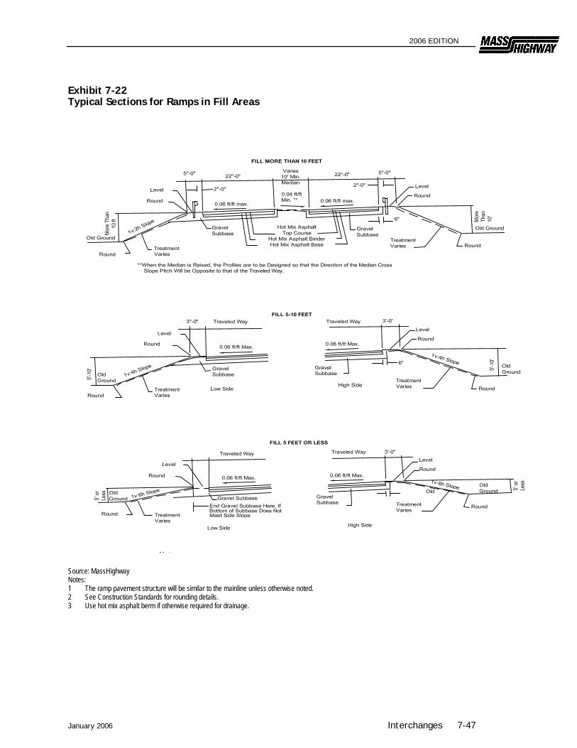
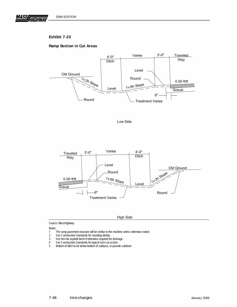
7.7.1.2 Cross Section Exhibits 7-22 and 7-23 illustrate typical ramp sections as summarized below:
Ramp Width – The typical width is 22 feet for one-lane ramps and 30 feet for two-lane ramps.
Cross Slope – Tangent sections of ramps should be uniformly sloped at 2.0% from the median edge to the opposite edge. MassHighway of has established the maximum superelevation rate at 6.0%.
Side Slopes – Fill and cut slopes should be as flat as possible. If feasible, they should be 1:6 or flatter, thus eliminating the need for guardrail.
Bridges and Underpasses – The full width of the ramp or loop should be carried over a bridge or beneath an underpass.
Lateral Clearances to Obstructions (Clear Zones) – Clear zone widths vary from 6-10 feet at 40 mph to 40-50 feet at 70 mph. The slope of the recovery area and traffic volume also plays a role in the selection of the width of the clear zone. (See AASHTO Roadside Design Guide as a guide for determining clear zone widths for highway ramps.) Ramps should have a lateral clearance on the right outside of the edge of traveled way of at least 6 feet and preferably 8 to 10 feet, and a lateral clearance on the left of at least 4 feet beyond the edge of the traveled way.
Exit Ramp Entrance Width – Where the through lane and exit ramp diverge, the typical width will be 25 feet. This width will be maintained until the gore nose is reached and transitioned to the standard 22 feet width at approximately a 12:1 rate.
Entrance Ramp Terminal Width – The standard 22 feet width will be transitioned to 14 feet width at the convergence with the through lane as shown in the Exhibits 7-30 at the end of this chapter.
7-46 Interchanges January 2006
2006 EDITION
January 2006 Interchanges 7-47
Exhibit 7-22 Typical Sections for Ramps in Fill Areas
Source: MassHighway Notes: 1 The ramp pavement structure will be similar to the mainline unless otherwise noted. 2 See Construction Standards for rounding details. 3 Use hot mix asphalt berm if otherwise required for drainage.
2006 EDITION
Exhibit 7-23 Ramp Section in Cut Areas
Source: MassHighway Notes: 1 The ramp pavement structure will be similar to the mainline unless otherwise noted. 2 See Construction Standards for rounding details. 3 Use hot mix asphalt berm if otherwise required for drainage. 4 See Construction Standards for typical rock cut section. 5 Bottom of ditch to be below bottom of subbase, or provide subdrain
7-48 Interchanges January 2006
2006 EDITION
7.7.1.3 Horizontal Alignment Horizontal alignment will largely be determined by the design speed and type of ramp as shown in Exhibit 7-24 and summarized below.
Design Speed – Ramps should be designed for minimum speeds indicated in Exhibit 7-21 unless restricted by site conditions.
Outer Connection – The outer connection at cloverleaf interchanges should be as directional as possible. However, if site conditions are restrictive, it may be allowed to follow a reverse path alignment around the inner loop.
Loops – Loop ramps should be on a continuously curved alignment in a compound curve arrangement, and should follow AASHTO guidelines for length.
Superelevation – MassHighway has established the maximum superelevation rate at 6.0%. It is preferred that the open highway conditions discussed in Chapter 4 should apply for transitioning to and from the needed superelevation. However, because of the restrictive nature of some ramps, this may not be possible. In addition, if the ramp will be terminated at an at-grade intersection with stop or signal control, it is not appropriate to superelevate curves fully near the terminus. The axis of rotation will be the profile edge.
Sight Distance – Sight distance along a ramp should be at least as great as the design stopping sight distance. There should be a clear view of the entire exit terminal, including the exit nose and a section of the roadway beyond the gore. An object height of 0.0 feet should be used to calculate the stopping sight distance at exit areas.
Two-Lane Ramps – The desirable minimum radius is 1,000 feet. See Exhibit 7-25 for typical two-lane exit treatments.
January 2006 Interchanges 7-49

2006 EDITION
Exhibit 7-24 Minimum Radii for Interchange Ramp Curves
Design Speed V (mph) 10 15 20 25 30 35 40 45
Side Friction Factor, f 0.38 0.32 0.27 0.23 0.20 0.18 0.16 0.15
Assumed Maximum Superelevation, e/100 0.00 0.00 0.02 0.04 0.06 0.06 0.06 0.06
Total e/100 + f 0.38 0.32 0.29 0.27 0.26 0.26 0.25 0.25
Calculated Minimum Radius R, (ft) 18 47 92 154 231 340 485 643
Suggested Design Minimum Radius (ft) 25 50 95 155 235 340 485 645 Note: For design speeds greater than 45 mph, use values for open highway conditions Source: MassHighway
Exhibit 7-25 Two-Lane Exit Terminals
Source: A Policy on Geometric Design of Highways and Streets, AASHTO, 2004. Chapter 10 Grade Separations and Interchanges
7-50 Interchanges January 2006
2006 EDITION
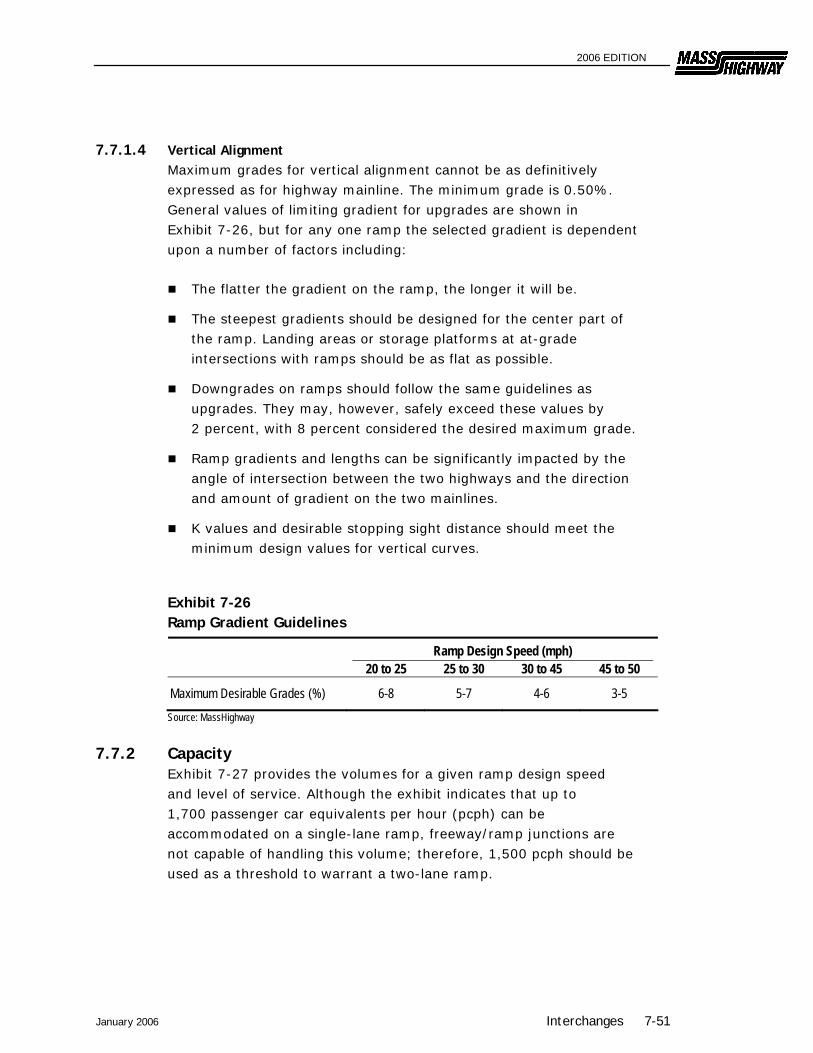
7.7.1.4 Vertical Alignment Maximum grades for vertical alignment cannot be as definitively expressed as for highway mainline. The minimum grade is 0.50%. General values of limiting gradient for upgrades are shown in Exhibit 7-26, but for any one ramp the selected gradient is dependent upon a number of factors including:
The flatter the gradient on the ramp, the longer it will be.
The steepest gradients should be designed for the center part of the ramp. Landing areas or storage platforms at at-grade intersections with ramps should be as flat as possible.
Downgrades on ramps should follow the same guidelines as upgrades. They may, however, safely exceed these values by 2 percent, with 8 percent considered the desired maximum grade.
Ramp gradients and lengths can be significantly impacted by the angle of intersection between the two highways and the direction and amount of gradient on the two mainlines.
K values and desirable stopping sight distance should meet the minimum design values for vertical curves.
Exhibit 7-26 Ramp Gradient Guidelines
Ramp Design Speed (mph) 20 to 25 25 to 30 30 to 45 45 to 50
Maximum Desirable Grades (%) 6-8 5-7 4-6 3-5 Source: MassHighway
7.7.2 Capacity Exhibit 7-27 provides the volumes for a given ramp design speed and level of service. Although the exhibit indicates that up to 1,700 passenger car equivalents per hour (pcph) can be accommodated on a single-lane ramp, freeway/ramp junctions are not capable of handling this volume; therefore, 1,500 pcph should be used as a threshold to warrant a two-lane ramp.
January 2006 Interchanges 7-51

2006 EDITION
Exhibit 7-27 Approximate Service Volumes for Single-lane Ramps
Ramp Design Speed (mph) LOS < 20 20 - 30 30 - 45 45 - 50 >50
A -- -- -- -- 700 B -- -- -- 1,000 1050 C -- -- 1,125 1,250 1,300 D -- 1,025 1,200 1,325 1,500 E 1,250 1,450 1,6001 1,6501 1,7001
F --Widely Variable -- Source, Highway Capacity Manual, Washington DC 2000 Note: Based on Peak Hour Factor of 1.0, service volumes expressed in passenger cars per hour. 1 For two-Lane Ramps, Multiply Above Values By 1.7 for < 20 mph, 1.8 for 20-30 mph & 45-50 mph, 1.9 for 30-45 mph,
and 2.0 for ≥50 mph -- LOS not achievable due to restricted design speeds The minimum radius of a two-lane ramp should be 1,000 feet. The capacity of a loop ramp is about 1,250 pcph; however, two-lane loop ramps are very undesirable because of their restrictive geometry. Therefore, if a left-turn movement will exceed 1,250, a directional or semi-directional connection may be needed. Ramps must be designed with sufficient capacity to avoid backups on the main line. The Highway Capacity Manual further discusses the capacity of ramps.
7.8 Ramp/Minor Road Intersections
At service interchanges the ramp or loop normally intersects the minor road at-grade at approximately a 90-degree angle. This intersection should be treated as described in Chapter 6. This will involve a consideration of the necessary traffic control devices, capacity, and the physical geometric design elements such as sight distance, angle of intersection, grade, channelization, and turning lanes. However, the following points warrant special attention in the design of the ramp/minor road intersection:
Capacity – In urban areas where traffic volumes may be high, inadequate capacity of the ramp/minor road intersection can adversely affect the operation of the ramp/freeway junction. In a worst case situation the safety and operation of the mainline itself may be impaired by a back-up onto the freeway. Therefore, special attention should be given to providing sufficient capacity and storage for an at-grade intersection with the minor road. This could lead to the addition of lanes at the intersection or on the ramp
7-52 Interchanges January 2006

2006 EDITION
proper, or it could involve traffic signalization where the ramp traffic will be given priority. The analysis must also consider the operational impacts of the traffic characteristics on the intersecting road and signal timing for pedestrians. The procedures described in Chapter 6 should be used to calculate capacity and level of service for the ramp/minor road intersection.
Wrong-Way Movements – Most wrong-way movements originate at the ramp/minor road intersection. This intersection must be properly signed and designed to minimize the potential for a wrong-way movement.
Access Restrictions – Access to abutting properties or to other local road systems will interfere with the operation and safety of the interchange. Therefore, access must not be permitted from ramps or from the through roadways within the entire limits of the interchange. The no-access layout line should extend a minimum distance of 500 feet from all ramp terminals.
Sight Distance – Chapter 3 discusses the procedure for addressing sight distance at at-grade intersections. This procedure should be used for the ramp/minor road intersection. However, special attention must be given to the location of the bridge pier or abutment because these will present major sight distance obstacles. Methodologies for left-turning and right-turning vehicles presented in Chapter 3 should be used to determine if adequate sight distance is available. The combination of the bridge obstruction and the needed sight distance may result in relocating the ramp/minor road intersection to provide the needed sight distance.
Transition – The transition between high-speed driving on the mainline and safe operating speed on the minor road should take place on the ramps. Ramp and intersection design should require the driver to adopt a safe speed before entering the minor road. Free right-turn and merge is appropriate only when an acceleration taper can be provided, otherwise a full stop is preferred, especially in areas of high pedestrian and bicycle activity. Minor road design should be consistent with adjacent sections.
Multimodal Accommodation – The multimodal accommodation provided on the minor road should be continued through the interchange area. To improve driver response to pedestrian crosswalks and bicycle lanes, 90-degree intersections of ramps
January 2006 Interchanges 7-53
2006 EDITION
with the minor road are preferable over merge/diverge areas. With 90-degree intersections, the approaches to pedestrian and bicycle accommodation discussed in Chapter 6 are applicable. In cases where vehicular capacity considerations or existing infrastructure configurations result in merge/diverge areas on the minor road (such as at full cloverleafs), special consideration should be given to the treatment of bicycle lanes as illustrated in Exhibits 7-28 and 7-29. Although full cloverleaf configurations are undesirable in areas with high pedestrian activity, crosswalks should be located so their visibility is maximized for approaching traffic and appropriate warning signs should be provided. With cloverleaf configurations, the designer needs to accommodate bicycle travel across the merge and diverge areas using the options illustrated in Exhibit 7-28 and 7-29. Considerations for selecting an approach to accommodating bicycle travel through these areas are listed below:
90-degree ramp intersections are preferred for bicycle accommodation and should be used in areas with significant bicycle activity when possible.
Option 1 treatments require a bicyclist to stop before crossing a ramp and are best-suited to high-volume, high speed roadways, where weaving of motor vehicle and bicycle traffic may be hazardous.
Option 1 may not be feasible where there are substantial grade changes through the interchange gore area.
Option 2 treatments are suitable in low-speed environments since the cyclist and motor vehicle must weave at the merge and diverge areas.
Additional advance warning signage and pavement markings can be helpful in accommodating bicycle travel with either of these options.
7-54 Interchanges January 2006

2006 EDITION
January 2006 Interchanges 7-55
Exhibit 7-28 Bicycle Lane Crossing of Diverging Ramp
Note: All signs and markings, including advance signage and markings, shall conform to the MUTCD. Chapter 3 Pavement Markings Source: Guide for the Development of Bicycle Facilities, AASHTO, 1999. Chapter 2 Design

2006 EDITION
Exhibit 7-29 Bicycle Lane Crossing of Merging Ramp
Note: All signs and markings, including advance signage and markings, shall conform to the MUTCD. Source: Guide for the Development of Bicycle Facilities, AASHTO, 1999. Chapter 2 Design
7-56 Interchanges January 2006

2006 EDITION
January 2006 Interchanges 7-57
Exhibit 7-30a Freeway Exit at Interchange (Via Outer Connection of Cloverleaf-Type Ramp)
The e
xit ab
ove i
s app
licab
le to
the ou
ter co
nnec
tion i
n Qu
adra
nt “B
” and
“D”.
NOTE
S:1.
Whe
n the
grad
e of th
e fre
eway
is gr
eater
than
2%, in
creas
e or d
ecre
ase t
he de
celer
ation
leng
th
acco
rding
to E
xhibi
t 7-1
5. 2.
On th
e ram
p bey
ond t
he go
re no
se, th
e rad
ius of
each
succ
essiv
e com
poun
d cur
ve sh
ould
be at
leas
t 50
% of
the r
adius
of th
e pre
cedin
g flat
ter cu
rve.
3.
The m
inimu
m len
gth of
each
curve
shou
ld all
ow su
fficien
t dec
elera
tion d
istan
ce fo
r the
desig
n spe
ed of
the
follow
ing sh
arpe
r cur
ve
4. Th
e sup
erele
vatio
n on t
he de
celer
ation
lane
shou
ld be
deve
loped
so th
at ful
l sup
erele
vatio
n (typ
ically
0.06
) is
attain
ed a
the ex
it gor
e (PC
C of
R=12
00 ft
curve
).
5.
4-lan
e fre
eway
is sh
own f
or ill
ustra
tion.
This
desig
n also
appli
es to
free
ways
with
mor
e tha
n 4 la
nes.
6. Th
e dec
elera
tion d
istan
ce sh
own i
s an e
xamp
le for
a sp
ecific
set o
f spe
eds a
nd su
pere
levati
on.
Use E
xhibi
t 7-1
3 to d
eterm
ine th
e nec
essa
ry de
celer
ation
dista
nce.
Sour
ce: M
assh
ighwa
y

2006 EDITION
Exhibit 7-30b Freeway Exit at Interchange (Via Inner Loop Connection of Cloverleaf-Type Ramp)
The e
xit de
tails
abov
e are
appli
cable
to a
ramp
in
Quad
rant
“A” w
hen t
here
is no
ramp
in Q
uadr
ant
“B” a
nd to
a ra
mp in
Qua
dran
t “C”
whe
n the
re is
no
ramp
in Q
uadr
ant “
D”.
NOTE
S:1.
Whe
n the
grad
e of th
e fre
eway
is gr
eater
than
2%, in
creas
e or d
ecre
ase t
he
acce
lerati
on le
ngth
acco
rding
to E
xhibi
t 7-1
5. 2.
On t
he ra
mp be
yond
the g
ore n
otes,
the ra
dius o
f eac
h suc
cess
ive co
mpou
nd cu
rve
shou
ld be
at le
ast 5
0% of
the r
adius
of th
e pre
cedin
g flat
ter cu
rve.
3. T
he m
inimu
m len
gth of
each
curve
shou
ld all
ow su
fficien
t dec
elera
tion d
istan
ce fo
r the
desig
n spe
ed of
the f
ollow
ing sh
arpe
r cur
ve, if
comp
ound
curva
ture i
s use
d. 4.
The s
uper
eleva
tion o
n the
dece
lerati
on la
ne sh
ould
be de
velop
ed so
that
full
supe
relev
ation
(typ
ically
0.06
) is at
taine
d a th
e exit
gore
(PCC
of R
=100
0 ft c
urve
).
5. 4-
lane f
reew
ay is
show
n for
illus
tratio
n. Th
is de
sign a
lso ap
plies
to fr
eewa
ys w
ith
more
than
4 lan
es.
6. Th
e dec
elera
tion d
istan
ce sh
own i
s an e
xamp
le for
a sp
ecific
set o
f spe
eds a
nd
supe
relev
ation
. Use
Exh
ibit 7
-13 t
o dete
rmine
the n
eces
sary
dece
lerati
on di
stanc
e . So
urce
: Mas
shigh
way
7-58 Interchanges January 2006

2006 EDITION
January 2006 Interchanges 7-59
Exhibit 7-30c Freeway Exit at Diamond Interchange
NOTE
S:1.
Whe
n the
grad
e of th
e fre
eway
is gr
eater
than
2%, in
creas
e or d
ecre
ase t
he
dece
lerati
on le
ngth
acco
rding
to E
xhibi
t 7-1
5. 2.
On t
he ra
mp be
yond
the g
ore n
otes,
the ra
dius o
f eac
h suc
cess
ive co
mpou
nd cu
rve
shou
ld be
at le
ast 5
0% of
the r
adius
of th
e pre
cedin
g flat
ter cu
rve.
3. T
he m
inimu
m len
gth of
each
curve
shou
ld all
ow su
fficien
t dec
elera
tion d
istan
ce fo
r the
desig
n spe
ed of
the f
ollow
ing sh
arpe
r cur
ve, if
comp
ound
curva
ture i
s use
d. 4.
The s
uper
eleva
tion o
n the
dece
lerati
on la
ne sh
ould
be de
velop
ed so
that
full
supe
relev
ation
(typ
ically
0.06
) is at
taine
d at th
e exit
gore
(PCC
of R
=120
0 ft c
urve
).
5. A
4-lan
e fre
eway
is sh
own f
or ill
ustra
tion.
This
desig
n also
appli
es to
free
ways
with
mo
re th
an 4
lanes
. 6 .
The d
ecele
ratio
n dist
ance
show
n is a
n exa
mple
for a
spec
ific se
t of s
peed
s and
su
pere
levati
on. U
se E
xhibi
t 7-1
3 to d
eterm
ine th
e nec
essa
ry de
celer
ation
dista
nce .
So
urce
: Mas
sHigh
way
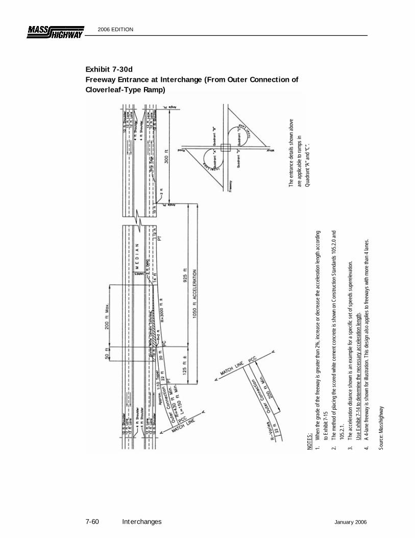
2006 EDITION
Exhibit 7-30d Freeway Entrance at Interchange (From Outer Connection of
NOTE
S:
Cloverleaf-Type Ramp)
The e
ntran
ce de
tails
show
n abo
ve
are a
pplic
able
to ra
mps i
n Qu
adra
nt “A
” and
“C”.
1. W
hen t
he gr
ade o
f the f
reew
ay is
grea
ter th
an 2%
, incre
ase o
r dec
reas
e the
acce
lera ti
on le
ngth
acco
rding
to
Exhib
it 7-1
5 2.
Th
e meth
od of
plac
ing th
e sco
red w
hite c
emen
t con
crete
is sh
own o
n Con
struc
tion S
tanda
rds 1
05.2.
0 and
10
5.2.1.
3.
Th
e acc
elera
tion d
istan
ce sh
own i
s an e
xamp
le for
a sp
ecific
set o
f spe
eds s
uper
eleva
tion.
Us
e Exh
ibit 7
-14 t
o dete
rmine
the n
eces
sary
acce
lerati
on le
ngth.
4.
A 4-
lane f
reew
ay is
show
n for
illus
tratio
n. Th
is de
sign a
lso ap
plies
to fr
eewa
ys w
ith m
ore t
han 4
lane
s. So
urce
: Mas
shigh
way
7-60 Interchanges January 2006

2006 EDITION
January 2006 Interchanges 7-61
Exhibit 7-30e Freeway Entrance at Interchange (From Inner Connection of Cloverleaf-Type Ramp)
The e
xit d
etails
abov
e are
ap
plica
ble to
ramp
s in
Quad
rant
“B” a
nd “C
”.
NOTE
S:1.
Whe
n the
grad
e of th
e fre
eway
is gr
eater
than
2%, in
creas
e or d
ecre
ase t
he ac
celer
ation
leng
th ac
cord
ing to
Exh
ibit 7
-15.
2. On
the r
amp b
eyon
d the
gore
nose
, the r
adius
of ea
ch su
cces
sive c
ompo
und c
urve
shou
ld be
at le
ast 5
0% of
the r
adius
of
the pr
eced
ing fla
tter c
urve
. 3.
The
mini
mum
length
of ea
ch cu
rve sh
ould
allow
suffic
ient d
ecele
ratio
n dist
ance
for t
he de
sign s
peed
of th
e foll
owing
sh
arpe
r cur
ve, if
comp
ound
curva
ture i
s use
d. 4.
The s
uper
eleva
tion o
n the
dece
lerati
on la
ne sh
ould
be de
velop
ed so
that
full s
uper
eleva
tion (
typica
lly 0.
06) is
attai
ned a
the
exit g
ore (
PCC
of R=
1200
ft cu
rve).
5.
A 4-
lane f
reew
ay is
show
n for
illus
tratio
n. Th
is de
sign a
lso ap
plies
to fr
eewa
ys w
ith m
ore t
han 4
lane
s. So
urce
: Mas
sHigh
way
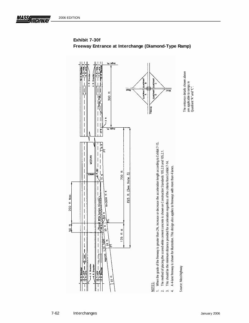
2006 EDITION
Exhibit 7-30f Freeway Entrance at Interchange (Diamond-Type Ramp)
The e
ntran
ce de
tails
show
n abo
ve
are a
pplic
able
to ra
mps i
n Qu
adra
nt “A
” and
“C”.
NOTE
S:1.
Whe
n the
grad
e of th
e fre
eway
is gr
eater
than
2%, in
creas
e or d
ecre
ase t
he ac
celer
ation
leng
th ac
cord
ing to
Exh
ibit 7
-15.
2.
The m
ethod
of pl
acing
the s
core
d whit
e cem
ent c
oncre
te is
show
n on C
onstr
uctio
n Stan
dard
s 105
.2.0 a
nd 10
5.2.1.
3.
Th
is sh
ould
be th
e mini
mum
distan
ce pr
ovide
d for
acce
lerati
on re
gard
less o
f the c
riteria
from
Exh
ibit 7
-14.
4.
A
4-lan
e fre
eway
is sh
own f
or ill
ustra
tion.
This
desig
n also
appli
es to
free
ways
with
mor
e tha
n 4 la
nes.
Sour
ce: M
assh
ighwa
y
7-62 Interchanges January 2006
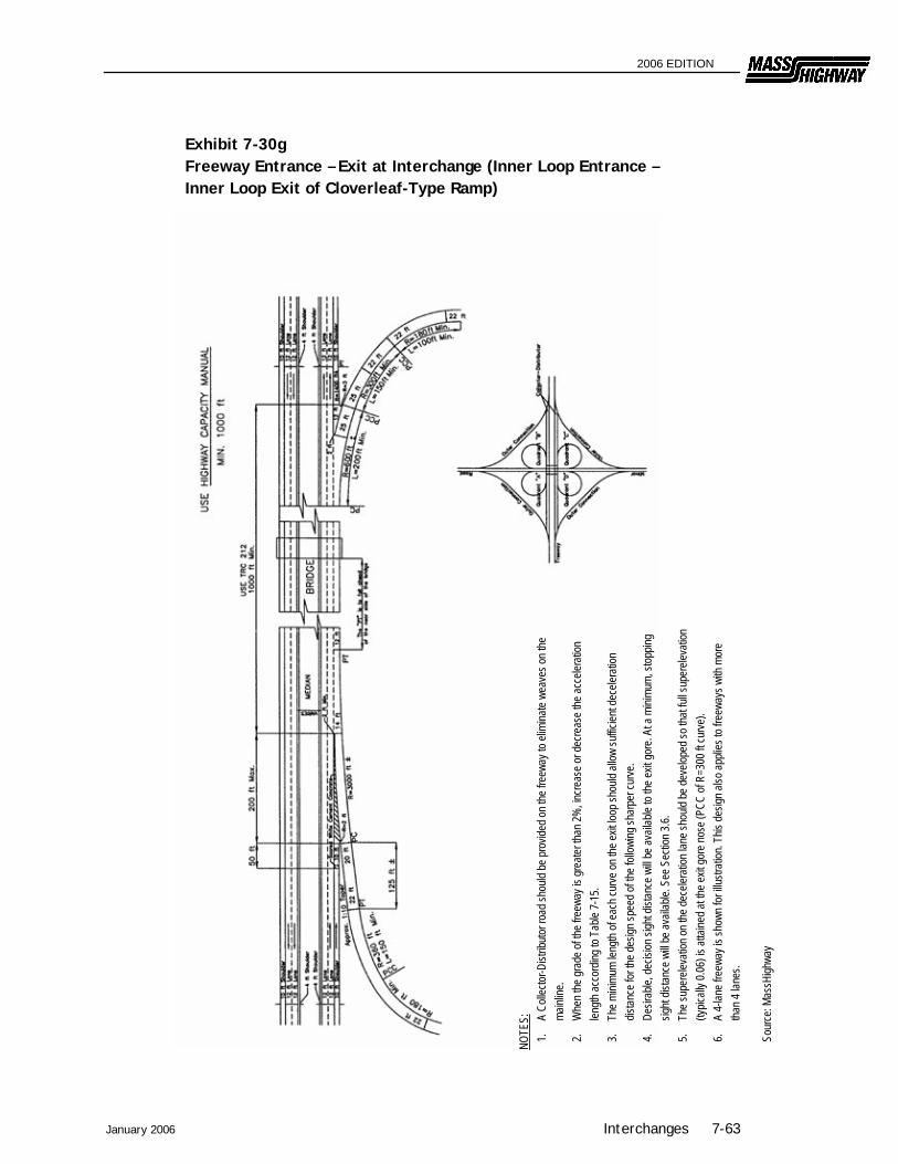
2006 EDITION
January 2006 Interchanges 7-63
Exhibit 7-30g Freeway Entrance – Exit at Interchange (Inner Loop Entrance – Inner Loop Exit of Cloverleaf-Type Ramp)
NOTE
S:1.
A Co
llecto
r-Dist
ributo
r roa
d sho
uld be
prov
ided o
n the
free
way t
o elim
inate
weav
es on
the
mainl
ine.
2.
Whe
n the
grad
e of th
e fre
eway
is gr
eater
than
2%, in
creas
e or d
ecre
ase t
he ac
celer
ation
len
gth ac
cord
ing to
Tab
le 7-
15.
3.
The m
inimu
m len
gth of
each
curve
on th
e exit
loop
shou
ld all
ow su
fficien
t dec
elera
tion
distan
ce fo
r the
desig
n spe
ed of
the f
ollow
ing sh
arpe
r cur
ve.
4. De
sirab
le, de
cision
sigh
t dist
ance
will
be av
ailab
le to
the ex
it gor
e. At
a mi
nimum
, stop
ping
sight
distan
ce w
ill be
avail
able.
See
Sec
tion 3
.6.
5.
The s
uper
eleva
tion o
n the
dece
lerati
on la
ne sh
ould
be de
velop
ed so
that
full s
uper
eleva
tion
(typic
ally 0
.06) is
attai
ned a
t the e
xit go
re no
se (P
CC of
R=3
00 ft
curve
). 6.
A
4-lan
e fre
eway
is sh
own f
or ill
ustra
tion.
This
desig
n also
appli
es to
free
ways
with
mor
e tha
n 4 la
nes.
Sour
ce: M
assH
ighwa
y
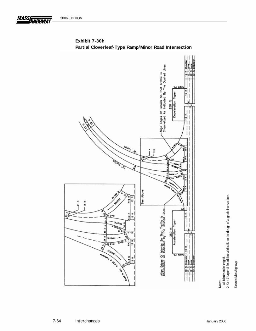
2006 EDITION
Exhibit 7-30h Partial Cloverleaf-Type Ramp/Minor Road Intersection
Notes
: 1.
All is
lands
to be
edge
d. 2.
See C
hapte
r 8 fo
r add
itiona
l deta
ils on
the d
esign
of at
-gra
de in
terse
ction
s. So
urce
: Mas
shigh
way
7-64 Interchanges January 2006

2006 EDITION
January 2006 Interchanges 7-65
Exhibit 7-30i Diamond-Type Ramp at Local Roadway
Notes
: 1.
The d
irecti
onal
islan
ds an
d ram
p med
ians a
re to
be ed
ged.
2. Se
e Cha
pt er 8
for a
dditio
nal d
etails
on th
e des
ign of
at-g
rade
int
erse
ction
s. 3.
200 f
eet is
typic
al. M
ust m
eet u
nsign
alize
d inte
rsecti
on si
gn
distan
ce cr
iteria
. So
urce
: Mas
shigh
way

2006 EDITION
Exhibit 7-30j Diamond-Type Ramp at a Local Roadway with High Levels of Bicycle and Pedestrian Activity
Notes
: 1.
All is
lands
to be
edge
d.2. S
ee C
hapte
r 8 fo
r add
itiona
l deta
ils on
the d
esign
of
at-gr
ade i
nterse
ction
s. 3.
8-foo
t usa
ble sh
oulde
r ass
umed
on lo
cal ro
ad.
Sour
ce: M
assH
ighwa
y
7-66 Interchanges January 2006

2006 EDITION
January 2006 Interchanges 7-67
Exhibit 7-30k Partial Cloverleaf-Type Ramp at a Local Roadway with High Levels of Bicycle and Pedestrian Activity
Notes
: 1.
All is
lands
to be
edge
d. 2.
See C
hapte
r 8 fo
r add
itiona
l deta
ils on
the d
esign
of at
-gra
de in
terse
ction
s. So
urce
: Mas
sHigh
way

2006 EDITION
7.9 For Further Information
A Policy on Geometric Design of Highways and Streets, AASHTO, 2004.
Guide for the Development of Bicycle Facilities, AASHTO, 1999.
Guide for the Planning and Design of Pedestrian Facilities, AASHTO, 2004
A Guide to Achieving Flexibility in Highway Design, AASHTO, 2004.
Highway Capacity Manual, Transportation Research Board, 2000.
Manual on Uniform Traffic Control Devices, Federal Highway Administration, 2003.
7-68 Interchanges January 2006
Related Documents