CHAPTER 7 Heat Exchanger

Welcome message from author
This document is posted to help you gain knowledge. Please leave a comment to let me know what you think about it! Share it to your friends and learn new things together.
Transcript

CHAPTER 7Heat Exchanger

Heat Transfer• How is the heat transfer?
• Mechanism of Convection
• Applications .
• Mean fluid Velocity and Boundary and their effect on the rate of heat transfer.
• Fundamental equation of heat transfer
• Logarithmic-mean temperature difference.
• Heat transfer Coefficients.
• Heat flux and Nusselt correlation
• Simulation program for Heat Exchanger
How is the heat transfer?
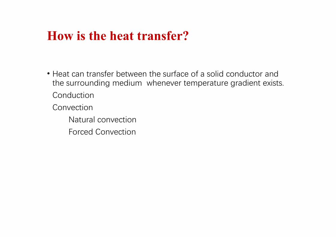
• Heat can transfer between the surface of a solid conductor and the surrounding medium whenever temperature gradient exists.
Conduction
Convection
Natural convection
Forced Convection

Mechanisms of heat transfer
There exist 3 basic mechanisms of heat transfer between different bodies (or inside a continuous body)
Conduction in solids or stagnant fluids
Convection inside moving fluids, but first of all we shall discuss heat transfer from flowing fluid to a solid wall
Radiation (electromagnetric waves) the only mechanism of energy transfer in an empty space
Aim of analysis is to find out relationships between heat flows (heat fluxes) and driving forces (temperature differences)

• Natural and forced Convection• Natural convection occurs whenever heat flows between a solid and fluid,
or between fluid layers.
• As a result of heat exchange• Change in density of effective fluid layers taken place, which causes
upward flow of heated fluid.
• If this motion is associated with heat transfer mechanism only, then it is called Natural Convection

Forced Convection
If this motion is associated by mechanical means such as pumps, gravity or fans, the movement of the fluid is enforced.
And in this case, we then speak of Forced convection.
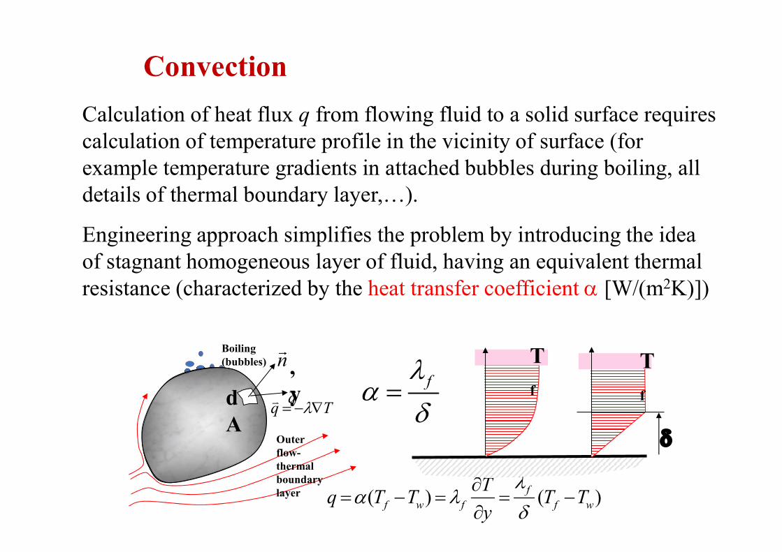
Convection
Calculation of heat flux q from flowing fluid to a solid surface requires calculation of temperature profile in the vicinity of surface (for example temperature gradients in attached bubbles during boiling, all details of thermal boundary layer,…).
Engineering approach simplifies the problem by introducing the idea of stagnant homogeneous layer of fluid, having an equivalent thermal resistance (characterized by the heat transfer coefficient [W/(m2K)])
Tq
( ) ( )ff w f f w
Tq T T T T
y
n
dA
q
Boiling (bubbles)
Outer flow-thermal boundary layer
,y
T
f
T
f
f

Convection – Nu,Re,Pr
Heat transfer coefficient depends upon the flow velocity (u), thermodynamic parameters of fluid () and geometry (for example diameter of sphere or pipe D). Value is calculated from engineering correlation using dimensionless criteria
Nusselt number (dimensionless , reciprocal thickness of boundary layer)
Reynolds number (dimensionless velocity, ratio of intertial and viscous forces)
Prandl number (property of fluid, ratio of viscosity and temperature diffusivity)
uD
Re
k
hDNu
a
Pr
Rem: is dynamic viscosity [Pa.s], kinematic viscosity [m2/s], =/
And others
Pe=Re.Pr Péclet numberGz=Pe.D/L Graetz number (D-diameter, L-length of pipe)
RayleighDe=Re√D/Dc Dean number (coiled tube, Dc diameter of curvature)

Convection Turbulent flow
Turbulent flow is characterised by the energy transport by turbulent eddies which is more intensive than the molecular transport in laminar flows. Heat transfer coefficient and the Nusselt number is greater in turbulent flows. Basic differences between laminar and turbulent flows are:
Nu is proportional to in laminar flow, and in turbulent flow.
Nu doesn’t depend upon the length of pipe in turbulent flows significantly (unlike the case of laminar flows characterized by rapid decrease of Nu with the length L)
Nu doesn’t depend upon the shape of cross section in the turbulent flow regime (it is possible to use the same correlations for eliptical, rectangular…cross sectionsusing the concept of equivalent diameter – this cannot be done in laminar flows)
3 u 0.8u
The simplest correlation for hydraulically smooth pipe designed by Dittus Boelter is frequently used (and should be memorized)
0.80.023Re PrmNu m=0.4 for heating
m=0.3 for coolingSimilar result follows from the Colburn analogy 3/18.0 PrRe023.0Nu

Convection Turbulent flow
,PrReL
D,Nu
,
W
,// 140
4204332
18010370
2300<Re<105 0,6<Pr<500
Nu
f
f W
n
Re Pr
. . Pr /8 56 35 92 12 3n=0,11 TW>T (heating)
n=0,25 TWT (cooling)
Dittus Boelter correlation assumes that Nu is independent of L. For very short pipes (L/D<60) Hausen’s correlation can be applied
Effect of wall roughness can be estimated from correlations based upon analogies between momentum and heat transfer (Reynolds analogy, Colburn analogy, Prandtl Taylor analogy). Results from hydraulics (pressure drop, friction factor f) are used for heat transfer prediction. Example is correlation Pětuchov (1970) recommended in VDI Warmeatlas
104Re5,106 0,5Pr2000 0,08W /40.
Friction factor

Heat Exchangers Defination• A device whose primary purpose is the transfer of energy
between two fluids is named a Heat Exchanger.

Applications of Heat Exchangers
Heat Exchangers prevent car engine
overheating and increase efficiency
Heat exchangers are used in Industry for
heat transfer
Heat exchangers are used in AC and
furnaces

What are heat exchangers for?
• To get fluid streams to the right temperature for the next process• reactions often require feeds at high temp.
• To condense vapours
• To evaporate liquids
• To recover heat to use elsewhere
• To reject low-grade heat
• To drive a power cycle

Types
Heat Exchanger Types
Heat exchangers are uired for energy conversion and utilization. They involve heat exchange between two fluids separated by a solid and encompass a wide range of flow configurations.• Concentric-Tube Heat Exchangers
Parallel Flow Counterflow
Simplest configuration.
Superior performance associated with counter flow.

Types (cont.)
• Cross-flow Heat Exchangers
Finned-Both FluidsUnmixed
Unfinned-One Fluid Mixedthe Other Unmixed
For cross-flow over the tubes, fluid motion, and hence mixing, in the transversedirection (y) is prevented for the finned tubes, but occurs for the unfinned condition.
Heat exchanger performance is influenced by mixing.

Types (cont.)
• Shell-and-Tube Heat Exchangers
One Shell Pass and One Tube Pass
Baffles are used to establish a cross-flow and to induce turbulent mixing of theshell-side fluid, both of which enhance convection.
The number of tube and shell passes may be varied, e.g.:
One Shell Pass,Two Tube Passes
Two Shell Passes,Four Tube Passes

Types (cont.)
• Compact Heat Exchangers Widely used to achieve large heat rates per unit volume, particularly when
one or both fluids is a gas.
(a) Fin-tube (flat tubes, continuous plate fins)(b) Fin-tube (circular tubes, continuous plate fins)(c) Fin-tube (circular tubes, circular fins)(d) Plate-fin (single pass)(e) Plate-fin (multipass)

Shell and Tube
Typical shell and tube exchanger as used in the process industry

Shell-side flow

Complete shell-and-tube

Example of an exchanger
Bundle for shell-and-tube exchanger

Coverage of Shell Area

Overall Heat Transfer Coefficient for the Heat Exchanger
The overall heat transfer coefficient for clean surface (Uc) is given by
Considering the total fouling resistance, the heat transfer coefficient for fouled surface (Uf) can be calculated from the following expression:

Principle of Heat Exchanger• First Law of Thermodynamic: “Energy is conserved.”
generatedsin out
outin ewQhmhmdt
dE
ˆ.ˆ.
outin
hmhm ˆ.ˆ. h
hphh TCmAQ ...
ccpcc TCmAQ ...
0 0 0 0
•Control Volume
Cross Section Area
HOT
COLD
Thermal Boundary Layer

Q hot Q cold
Th Ti,wall
To,wall
Tc
Region I : Hot Liquid-Solid Convection
NEWTON’S LAW OF CCOLING
dATThQd iwhh .. Region II : Conduction Across Copper Wall
FOURIER’S LAW dr
dTkqd .
Region III: Solid –Cold Liquid Convection
NEWTON’S LAW OF CCOLING dATThQd cowc ..
Thermal boundary layerEnergy moves from hot fluid to a surface by convection, through the wall by conduction, and then by convection from the surface to the cold fluid.

• Velocity distribution and boundary layer
When fluid flow through a circular tube of uniform cross-suction and fully developed,
The velocity distribution depend on the type of the flow.
In laminar flow the volumetric flowrate is a function of the radius.
V u2rdrr 0
r D / 2
V = volumetric flowrate
u = average mean velocity

In turbulent flow, there is no such distribution.
• The molecule of the flowing fluid which adjacent to the surface have zero velocity because of mass-attractive forces. Other fluid particles in the vicinity of this layer, when attempting to slid over it, are slow down by viscous forces.
r
Boundary layer

• Accordingly the temperature gradient is larger at the wall and through the viscous sub-layer, and small in the turbulent core.
• The reason for this is
1) Heat must transfer through the boundary layer by conduction.
2) Most of the fluid have a low thermal conductivity (k)
3) While in the turbulent core there are a rapid moving eddies, which they are equalizing the temperature.
heating
cooling
Tube wall
Twh
Twc
Tc
Metalwall
Warm fluid
cold fluid)( TThAQ
ThAQ
w
)( TTAk
Q w
h

Region I : Hot Liquid –Solid Convection
owiw
i
o
copper TT
rr
LkQ ,,
ln
2.
ihiwh Ah
QTT
.
ATThQ iwhhot ..
Region II : Conduction Across Copper Wall Lk
rr
Q
TTcopper
i
o
wowi 2.
ln.
,,
Region III : Solid –Cold Liquid Convection
occwallo Ah
QTT
.,
oiwcc ATThQ ,
+
occopper
i
o
ihch AhLk
rr
AhQTT
.
1
2.
ln
.
1
ch TTAUQ ..
1
1
.
ln.
.
coldicopper
i
oo
ihot
o
hrk
rr
r
rh
rU
U = The Overall Heat Transfer Coefficient [W/m.K]
321 RRR
QTT ch
U 1
A .R
ro
ri

Calculating Using Log Mean Temperature
coldhot QdQdQd
ch TTT ch dTdTTd )(
hhphh dTCmQd ..
ccpcc dTCmQd ..
Hot Stream :
Cold Stream:
cpc
chph
h
Cm
Qd
Cm
QdTd
..)(
dATUQd ..
cpc
hph CmCm
dATUTd.
1
.
1...)(
2
1
2
1
..
1
.
1.
)( A
Acpc
hph
T
TdA
CmCmU
T
Td
outc
inc
outh
inhch TTTT
Q
AUTT
Q
AU
T
T
...
ln1
2
2
1
2
1
..)( A
Ac
c
h
hT
TdA
Q
T
Q
TU
T
Td
1
2
12
ln
.
TT
TTAUQ
Log Mean Temperature

CON CURRENT FLOW
1
2
12
lnT
T
TTTLn
731 TTTTT inc
inh
1062 TTTTT outc
outh
COUNTER CURRENT FLOW
1062 TTTTT inc
outh
731 TTTTT outc
inh
U ?m h . ?C p
h . T3 T6 A.TLn
?m c . ?C p
c . T7 T10 A.TLn
T1T2
T4 T5
T3
T7 T8 T9
T10
T6
Counter - Current Flow
T1 T2T4 T5
T6T3
T7T8 T9
T10
Parallel Flow
Log Mean Temperature evaluation
T1
A
1 2
T2
T3
T6
T4 T6
T7 T8
T9
T10
Wall∆T1
∆T2
∆ A
A
1 2
T1
A
1 2
T2
T3
T6
T4 T6
T7 T8
T9
T10
Wall
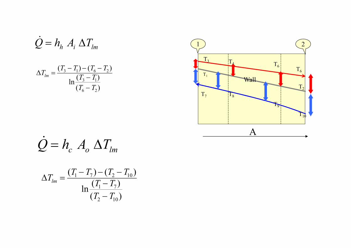
lmih TAhQ
Tlm (T3 T1) (T6 T2)
ln(T3 T1)(T6 T2)
lmoc TAhQ
Tlm (T1 T7) (T2 T10)
ln(T1 T7)
(T2 T10)

Nu f (Re, Pr, L / D , b / o )
DIMENSIONLESS ANALYSIS TO CHARACTERIZE A HEAT EXCHANGER
..Dv
k
C p .k
Dh.
Nu a.Reb .Pr c•Further Simplification:
Can Be Obtained from 2 set of experiments
One set, run for constant Pr
And second set, run for constant Re
)( TTAk
Q w
h

•For laminar flow
Nu = 1.62 (Re*Pr*L/D)
•Empirical Correlation
14.0
3/18.0 .Pr.Re.026.0
o
bLnNu
•Good To Predict within 20%•Conditions: L/D > 10
0.6 < Pr < 16,700Re > 20,000
•For turbulent flow
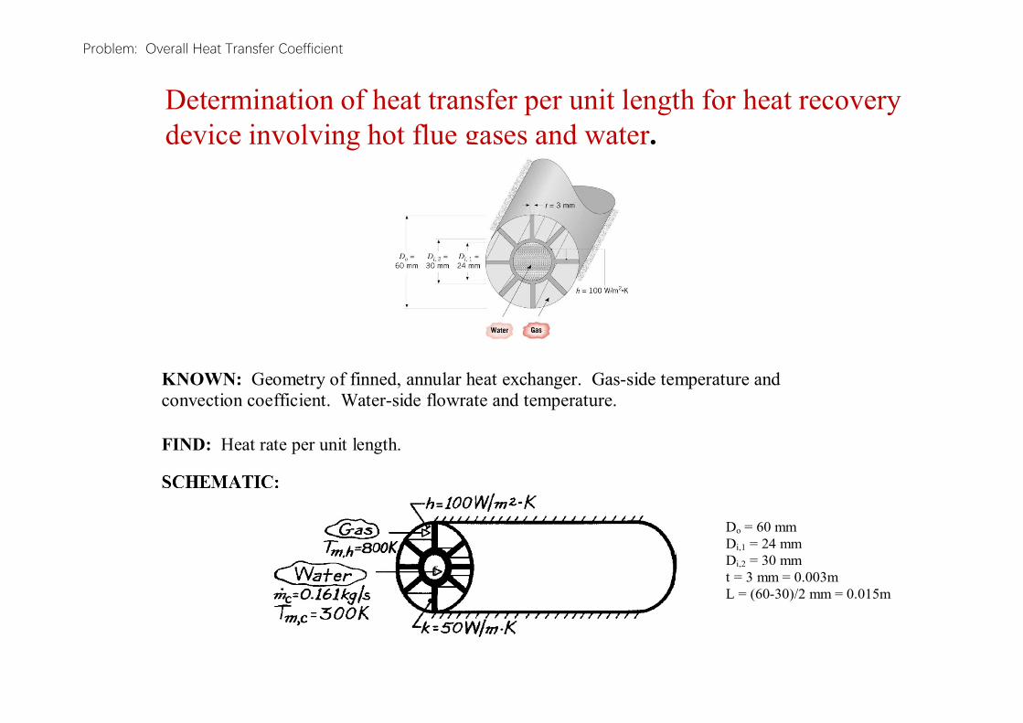
Problem: Overall Heat Transfer Coefficient
Determination of heat transfer per unit length for heat recoverydevice involving hot flue gases and water.
KNOWN: Geometry of finned, annular heat exchanger. Gas-side temperature and convection coefficient. Water-side flowrate and temperature.
FIND: Heat rate per unit length.
Do = 60 mm Di,1 = 24 mm Di,2 = 30 mm t = 3 mm = 0.003m L = (60-30)/2 mm = 0.015m

Problem: Overall Heat Transfer Coefficient (cont.)
ASSUMPTIONS: (1) Steady-state conditions, (2) Constant properties, (3) One-dimensional conduction in strut, (4) Adiabatic outer surface conditions, (5) Negligible gas-side radiation, (6) Fully-developed internal flow, (7) Negligible fouling.
PROPERTIES: Table A-6, Water (300 K): k = 0.613 W/mK, Pr = 5.83, = 855 10-6 Ns/m2.
ANALYSIS: The heat rate is
where
m,h m,ccq UA T T
w oc c h1/ UA 1/ hA R 1/ hA
i,2 i,1 4w
ln D / D ln 30 / 24R 7.10 10 K / W.
2 kL 2 50 W / m K lm
Problem: Overall Heat Transfer Coefficient (cont.)
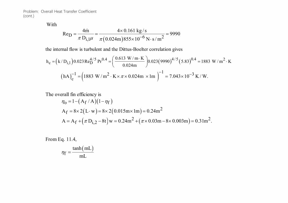
the internal flow is turbulent and the Dittus-Boelter correlation gives
4 / 5 0.44 / 5 0.4 2c i,1 D
0.613 W / m Kh k / D 0.023Re Pr 0.023 9990 5.83 1883 W / m K
0.024m
11 2 3chA 1883 W / m K 0.024m 1m 7.043 10 K / W.
The overall fin efficiency is o f f1 A / A 1
2fA 8 2 L w 8 2 0.015m 1m 0.24m
2 2f i,2A A D 8t w 0.24m 0.03m 8 0.003m 0.31m .
From Eq. 11.4,
ftanh mL
mL
With
D 6 2i,1
4m 4 0.161 kg / sRe 9990
D 0.024m 855 10 N s / m

Problem: Overall Heat Transfer Coefficient (cont.)
Hence f 0.800 /1.10 0.907 o f f1 A / A 1 1 0.24 / 0.31 1 0.907 0.928
11 2 2o hhA 0.928 100 W / m K 0.31m 0.0347 K / W.
It follows that
1 3 4cUA 7.043 10 7.1 10 0.0347 K / W
cUA 23.6 W / K
and q 23.6 W / K 800 300 K 11,800 W < for a 1m long section.
where
1/ 2 1/ 22 1m 2h / kt 2 100 W / m K / 50 W / m K 0.003m 36.5m
1/ 2 1mL 2h / kt L 36.5m 0.015m 0.55
1/ 2tanh 2h / kt L 0.499.

Problem: Overall Heat Transfer Coefficient (cont.)
COMMENTS: (1) The gas-side resistance is substantially decreased by using the fins
,2f iA D and q is increased.
(2) Heat transfer enhancement by the fins could be increased further by using a material of larger k, but material selection would be limited by the large value of Tm,h.

Problem: Ocean Thermal Energy Conversion
Problem : Design of a two-pass, shell-and-tube heat exchanger to supply vapor for the turbine of an ocean thermal energy conversion system based on a standard (Rankine) power cycle. The powercycle is to generate 2 MWe at an efficiency of 3%. Ocean water enters the tubes of the exchanger at 300K, and its desiredoutlet temperature is 292K. The working fluid of the powercycle is evaporated in the tubes of the exchanger at itsphase change temperature of 290K, and the overall heat transfercoefficient is known.
FIND: (a) Evaporator area, (b) Water flow rate.

Overall Heat Transfer Coefficient for the Heat Exchanger
The overall heat transfer coefficient for clean surface (Uc) is given by
Considering the total fouling resistance, the heat transfer coefficient for fouled surface (Uf) can be calculated from the following expression:

Outlet Temperature Calculation and Length of the Heat Exchanger
The outlet temperature for the fluid flowing through the tube is
The surface area of the heat exchanger for the fouled condition is :

and for the clean condition
where the LMTD is always for the counter flow.
The over surface design (OS) can be calculated from :

The length of the heat exchanger is calculated by

Problem: Ocean ThermalEnergy Conversion (cont)
ASSUMPTIONS: (1) Negligible heat loss to surroundings, (2) Negligible kinetic and potential energy changes, (3) Constant properties.
PROPERTIES: Table A-6, Water ( mT = 296 K): cp = 4181 J/kgK.
ANALYSIS: (a) The efficiency is
W 2MW
0.03.q q
Hence the required heat transfer rate is
2MW
q 66.7 MW.0.03
Also
m,CF300 290 292 290 C
T 5 C300 290
n292 290
t F = 1. Hence
7
2m,CF
q 6.67 10 WA
U F T 1200 W / m K 1 5 C
2A 11,100 m .
Problem: Ocean ThermalEnergy Conversion (cont)
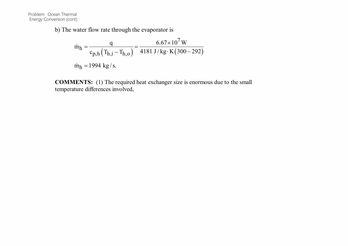
b) The water flow rate through the evaporator is
7
hp,h h,i h,o
q 6.67 10 Wm
4181 J / kg K 300 292c T T
hm 1994 kg / s.
COMMENTS: (1) The required heat exchanger size is enormous due to the small temperature differences involved,

Performance Analysis of Condensers

Steam Condenser
• Steam condenser is a closed space into which steam exits the turbine and is forced to give up its latent heat of vaporization.
• It is a necessary component of a steam power plant because of two reasons.
• It converts dead steam into live feed water.
• It lowers the cost of supply of cleaning and treating of working fluid.
• It is far easier to pump a liquid than a steam.
• It increases the efficiency of the cycle by allowing the plant to operate on largest possible temperature difference between source and sink.
• The steam’s latent heat of condensation is passed to the water flowing through the tubes of condenser.
• After steam condenses, the saturated water continues to transfer heat to cooling water as it falls to the bottom of the condenser called, hotwell.
• This is called subcooling and certain amount is desirable.
• The difference between saturation temperature corresponding to condenser vaccum and temperature of condensate in hotwell is called condensate depression.


Two-Pass Surface Condenser

Energy Balance of A Condenser
• Energy balance:
• The temperature rise of cooling water:
• 6 to 7 degree C for single pass.
• 7 to 9 degree C for single pass.
• 10 to 12 degree C for four pass.
WiWeWCWeccc TTCmhhm

Overall Heat Transfer Coefficient for the Condenser
The overall heat transfer coefficient for clean surface (Uc) is given by
Considering the total fouling resistance, the heat transfer coefficient for fouled surface (Uf) can be calculated from the following expression:

Cooling Water Outlet Temperature Calculation
The outlet temperature for the fluid flowing through the tube is
The surface area of the heat exchanger for the fouled condition is :
,
,, incw
cwpcw
fgsteamoutcw T
cm
hmT
hmLMTDFUAQ fsurfacetransfer

Correlations for Condensing Heat Transfer
• Choice of a correlation depend on whether you are looking at horizontal or vertical tubes, and whether condensation is on the inside or outside.
• Preliminaries
• The condensate loading on a tube is the mass flow of condensate per unit length that must be traversed by the draining fluid.
• The length dimension is perpendicular to the direction the condensate flows;
• the perimeter for vertical tubes,
• the length for horizontal tubes.

Condensate Loading
This can be used to calculate a Reynolds number
Perimeter
condensate offlor Mass
tubes.alfor vertic 0d
mcondensate
tubes.horizontalfor tube
condensate
L
m
filmoncondensati
4Re

•Flow is considered laminar if this Reynolds number is less than 1800. •The driving force for condensation is the temperature difference between the cold wall surface and the bulk temperature of the saturated vapor
The viscosity and most other properties used in the condensing correlations are evaluated at the film temperature, a weighted mean of the cold surface (wall) temperature and the (hot) vapor saturation temperature
surfacevapourwallsatdriving TTTTT
4
3
4
3 drivingsatwallsaturationsatfilm
TTTTTT

Wall Temperatures
• It is often necessary to calculate the wall temperature by an iterative approach.
• The summarized procedure is:
1.Assume a film temperature, Tf
2.Evaluate the fluid properties (viscosity, density, etc.) at this temperature
3.Use the properties to calculate a condensing heat transfer coefficient (using the correlations to be presented)
4.Calculate the wall temperature. The relationship will typically be something like
coolantsat
oo
satwall TT
Ah
UATT
1
1

5. Use the wall temperature to calculate a film temperature
6. Compare the calculated film temperature to that from the initial step. If not equal, reevaluate the properties and repeat.
Laminar Flow Outside Vertical Tubes
If condensation is occurring on the outside surface of vertical tubes, with a condensate loading such that the condensate Reynolds Number is less than 1800, the recommended correlation is:
31
2
3
3 Re
47.1
f
vfff
oncondensati
cond
gkh

•Since the vapor density is usually much smaller than that of the condensate film, some authors neglect it and use the film density squared in the denominator. •The presence of ripples (slight turbulence) improves heat transfer, so some authors advocate increasing the value of the coefficient by about 20%.
Another form of writing h is :
31
3
925.0
f
vfffcond
gkh
this may also be compensated for rippling (0.925*1.2=1.11).

Turbulent Flow Outside Vertical Tubes
When the condensate Reynolds Number is greater than 1800, the recommended correlation is :
31
2
34.0Re0076.0
f
vfffcond
gkh

Laminar Flow Outside Horizontal Tubes
When vapor condenses on the surface of horizontal tubes, the flow is almost always laminar. The flow path is too short for turbulence to develop. Again, there are two forms of the same relationship:
The constant in the second form varies from 0.725 to 0.729. The rippling condition (add 20%) is suggested for condensate Reynolds Numbers greater than 40.
31
2
3
3 Re
51.1
f
vfff
oncondensati
cond
gkh
41
0
3
725.0
dT
ghkh
drivingf
fgvfffcond

Condenser tubes are typically arranged in banks, so that the condensate which falls off one tube will typically fall onto a tube below.
The bottom tubes in a stack thus have thicker liquid films and consequently poorer heat transfer.
The correlation is adjusted by a factor for the number of tubes, becoming for the Nth tube in the stack
4
41
0
3
725.0N
h
dTN
ghkh top
drivingf
fgvfffcond
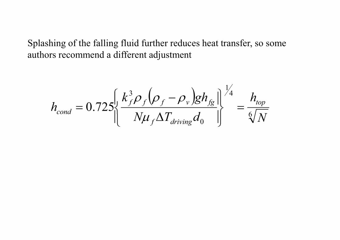
Splashing of the falling fluid further reduces heat transfer, so some authors recommend a different adjustment
6
41
0
3
725.0N
h
dTN
ghkh top
drivingf
fgvfffcond

Overall Heat Transfer Coefficient for the Condenser
The overall heat transfer coefficient for clean surface (Uc) is given by
Considering the total fouling resistance, the heat transfer coefficient for fouled surface (Uf) can be calculated from the following expression:
Related Documents