Page 506 Chapter 7: Graphics 7.1: Graphics in a GUI World In the last chapter we explored how to display text on the GUI display. Although text is unquestionably important in modern GUI applications, the first word in the phrase graphical user interface is graphical, not textual. Therefore, most people are probably a lot more interested in learning about how to do graphics under Windows rather than text. As it turns out, however, most GUI applications actually deal more with Windows controls and text objects rather than pure graphical objects. Nevertheless, knowing how to draw graphical objects in a window is an critical skill to master. In this chapter we ll look at the facilities Windows provides for drawing graphical images on the screen. 7.2: Types of Graphic Objects You Can Draw in Windows Windows attempts to present a device-independent view of output devices to your application software. This means that, to your programmer, a 24-bit video display card looks just like a printer, which looks just like a plot- ter, which looks just like a film recorder. Well, sort of. Though there are some very real-world differences between these types of output devices, differences of which your applications must be aware, for the most part you draw on the video display exactly the same way you draw on a printer. Indeed, in this chapter we will explore how to display graphic images on both a printer and a video display. Before describing the types of images you can draw on these various devices, it is probably worthwhile to point out that not all Windows output APIs are so universal. For example, game and multimedia applications that use Microsoft s Direct-X subsystem use different mechanisms for displaying their information; these mecha- nisms are quite a bit different than the ones we ll explore in this chapter (and higher performance), but the draw- back is that you cannot print such output to a printer device (though it may be perfectly possible to print such data to a video recorder device). So Windows does provide some special API functions for high-performance I/O devices (e.g., video input and output) that don t follow the standard GDI (Graphical Device Interface) model, but most Win32 applications will use the GDI model for output. Windows GDI model supports the ability to draw several primitive graphic objects on the display or a printer (we ll just use the term display from now on, but keep in mind that this discussion can apply to the printer as well). These primitives include lines, polylines, curves (arcs, chords, and bezier curves), rectangles, roundan- gles, ellipses and circles, filled regions, bitmaps, and text. We ve already beaten text to death in the last chapter, we ll take a look at these other primitives in this chapter. 7.3: Facilities That the Windows GDI Provides In addition to drawing, the Windows GDI provides several facilities to ease the creation of complex graphic images on the display. These facilities include the ability to change coordinate systems in use by the system (for example, using metric or English units rather than pixel units for string coordinates, the abilty to record a sequence of graphic drawing operations for later playback (as a metafile), the ability to maintain an outline (region or path) around an object, the ability to restrain drawing inside a given region (clipping), and the ability to control the color and fill pattern of objects drawn on the display. You ll see many of these features in action throughout this chapter.

Welcome message from author
This document is posted to help you gain knowledge. Please leave a comment to let me know what you think about it! Share it to your friends and learn new things together.
Transcript

Chapter 7: Graphics
7.1: Graphics in a GUI World
In the last chapter we explored how to display text on the GUI display. Although text is unquestionablyimportant in modern GUI applications, the first word in the phrase graphical user interface is graphical, nottextual. Therefore, most people are probably a lot more interested in learning about how to do graphics underWindows rather than text. As it turns out, however, most GUI applications actually deal more with Windowscontrols and text objects rather than pure graphical objects. Nevertheless, knowing how to draw graphical objectsin a window is an critical skill to master. In this chapter we ll look at the facilities Windows provides for drawinggraphical images on the screen.
7.2: Types of Graphic Objects You Can Draw in Windows
Windows attempts to present a device-independent view of output devices to your application software. Thismeans that, to your programmer, a 24-bit video display card looks just like a printer, which looks just like a plot-ter, which looks just like a film recorder. Well, sort of. Though there are some very real-world differencesbetween these types of output devices, differences of which your applications must be aware, for the most partyou draw on the video display exactly the same way you draw on a printer. Indeed, in this chapter we willexplore how to display graphic images on both a printer and a video display.
Before describing the types of images you can draw on these various devices, it is probably worthwhile topoint out that not all Windows output APIs are so universal. For example, game and multimedia applications thatuse Microsoft s Direct-X subsystem use different mechanisms for displaying their information; these mecha-nisms are quite a bit different than the ones we ll explore in this chapter (and higher performance), but the draw-back is that you cannot print such output to a printer device (though it may be perfectly possible to print suchdata to a video recorder device). So Windows does provide some special API functions for high-performance I/Odevices (e.g., video input and output) that don t follow the standard GDI (Graphical Device Interface) model, butmost Win32 applications will use the GDI model for output.
Windows GDI model supports the ability to draw several primitive graphic objects on the display or aprinter (we ll just use the term display from now on, but keep in mind that this discussion can apply to the printeras well). These primitives include lines, polylines, curves (arcs, chords, and bezier curves), rectangles, roundan-gles, ellipses and circles, filled regions, bitmaps, and text. We ve already beaten text to death in the last chapter,we ll take a look at these other primitives in this chapter.
7.3: Facilities That the Windows GDI Provides
In addition to drawing, the Windows GDI provides several facilities to ease the creation of complex graphicimages on the display. These facilities include the ability to change coordinate systems in use by the system (forexample, using metric or English units rather than pixel units for string coordinates, the abilty to record asequence of graphic drawing operations for later playback (as a metafile), the ability to maintain an outline(region or path) around an object, the ability to restrain drawing inside a given region (clipping), and the abilityto control the color and fill pattern of objects drawn on the display. You ll see many of these features in actionthroughout this chapter.
Page 506

7.4: The Device Context
In the last chapter you saw that Windows requires you to do all drawing through a device context. Whenresponding to a Windows w.WM_PAINT message, you d open a context with the BeginPaint macro invocationand you d end the drawing context with an invocation of the EndPaint macro invocation. Between those twopoints you could draw to your heart s content. In the last chapter, we only drew text on the screen, but you use thesame sequence of operations when drawing other graphic images to the display.
The last chapter introduced you to the BeginPaint, EndPaint, GetDC, GetWindowDC, and ReleaseDCmacros found in the wpa.hhf header file. You ll use those macros with all of the graphic drawing functions in thischapter as well. However, in addition to those macros/functions, there are a couple of additional routines you canuse when drawing data with the graphics primitives (including text). The first of these new functions to considerare w.CreateDC and w.DeleteDC:
staticCreateDC: procedure(
lpszDriver :string;lpszDevice :string;lpszOutput :string;
var lpInitData :DEVMODE);
@stdcall;@returns( "eax" );@external( "__imp__CreateDCA@16" );
DeleteDC: procedure(
hdc :dword);
@stdcall;@returns( "eax" );@external( "__imp__DeleteDC@4" );
For the w.CreateDC API call, the lpszDriver parameter should be the string DISPLAY or WINSPOOL(or the name of some other Windows print provider on your system, though this is usually WINSPOOL ), theother three parameters should normally be NULL (see the Win32 API documentation for details, but 99% of thetime you re going to use DISPLAY as the first parameter and NULL as the remaining three parameter values).This call returns a handle to the entire display device (meaning you can draw anywhere on the display, includingover the top of other windows on the display; obviously, you should only do this under special circumstances,well-behave applications don t arbitrarily draw on the display). When you are done using the device contextyou ve created via a w.CreateDC call, you call w.DeleteDC to free up that resource. Mainly, we ll use thew.CreateDC call to obtain the device context of a printer device, not the display device.
When creating complex bitmap objects, it s often convenient to build the bitmap in memory first, and thentransfer that bitmap to the display device (this, for example, prevents the object from flashing while you aredrawing it). You use the w.CreateCompatibleDC function call to do this:
staticCreateCompatibleDC: procedure(
hdc :dword);
Page 507

@stdcall;@returns( "eax" );@external( "__imp__CreateCompatibleDC@4" );
The w.CreateCompatibleDC requires a single parameter - the handle of an existing device context. Thisfunction creates an in-memory duplicate of that device context. You can draw to this context (by supplying thedevice context handle this function returns to the drawing routines) and Windows will store the image as a bit-map in memory. Later, you can transfer this bitmap to some actual output device. When you are done using thein-memory context you ve created with w.CreateCompatibleDC, you must call w.DeleteDC (passing the handlethat w.CreateCompatibleDC returns in EAX) to free up the resources associated with this device context. We llreturn to the use of this function a little later in this book.
As noted earlier, Windows provides the ability to record all of your graphic output requests in a special datastructure known as a metafile. The w.CreateMetaFile and w.CloseMetaFile functions provide a set of brack-ets between which Windows will record all GDI function calls to a file whose name you specify as the parameterto the w.CreateMetaFile function. The w.CloseMetaFile function gets passed the handle that w.CreateMeta-File returns in EAX, and w.CloseMetaFile returns a handle to the metafile that you can use in other API callsthat expect such a handle.
7.5: Obtaining and Using Device Context Information
A Device Context is an internal Windows data structure that maintains information about the current state ofthe device. As the last chapter notes, a device context maintains information likethe current font in use, the cur-rent output color, and other attributes such as line width, fill pattern, output size, and other such features. Also inthe last chapter, you learned about the w.GetDeviceCaps function that displays several of the values held in thedevice context structure and, in fact, the previous chapter presented a simple program to display various devicecapability values. In this section we ll explore the uses of some of this data.
As a reminder, here is the function prototype for the w.GetDeviceCaps API function:
static GetDeviceCaps: procedure ( hdc :dword; nIndex :dword ); @stdcall; @returns( "eax" ); @external( "__imp__GetDeviceCaps@8" );
The hdc parameter is the handle of the device context that you wish to query and the nIndex parameter is a spe-cial integer constant that specifies which value you wish this function to return in the EAX register (see Table 7-1for the constant that w.GetDeviceCaps accepts).
Table 7-1: Common GetDeviceCaps nIndex Values
Index Value Returned in EAX
w.HORZSIZE The horizontal size, in millimeters, of the display (or other device).
Page 508

rts
es
at
w.VERTSIZE The vertical size, in millimeters, of the display (or other device).
w.HORZRES The display’s width, in pixels.
w.VERTRES The display’s height, in pixels.
w.LOGPIXELSX The resolution, in pixels per inch, along the displays’ X-axis.
w.LOGPIXELSY The resolution, in pixels per inch, along the displays’ Y-axis.
w.BITSPIXEL The number of bits per pixel (specifying color information).
w.PLANES The number of color planes.
w.NUMBRUSHES The number of device-specific brushes available.
w.NUMPENS The number of device-specific pens available.
w.NUMFONTS The number of device specific fonts available.
w.NUMCOLORS Number of entries in the device’s color table.
w.ASPECTX Relative width of a device pixel used for drawing lines.
w.ASPECTY Relative height of a device pixel used for drawing lines.
w.ASPECTXY Diagonal width of the device pixel used for line drawing (45 degrees).
w.CLIPCAPS This is a flag value that indicates whether the device can clip images to arectangle. The w.GetDeviceCaps function returns one if the device suppoclipping, zero otherwise.
w.SIZEPALETTE Number of entries in the system palette (valid only if the display device usa palette).
w.NUMRESERVED Number of system reserved entries in the system palette (valid only if thedisplay device uses a palette).
w.COLORRES Actual color resolution of the device, in bits per pixel. For device drivers thuse palettes.
w.PHYSICALWIDTH For printing devices, the physical width of the output device in whatever units that device uses.
w.PHYSICALHEIGHT For printing devices, the physical height of the output device.
w.PHYSICALOFFSETX For printing devices, the horizontal margin.
w.PHYSICALOFFSETY For printing devices, the vertical margin.
w.SCALINGFACTORX For printing devices, the scaling factor along the X-axis.
w.SCALINGFACTORY For printing devices, the scaling factor along the Y-axis.
w.VREFRESH For display devices only: the current vertical refresh rate of the device, inHz.
Index Value Returned in EAX
Page 509

if
if
in l-
The values that w.GetDeviceCaps returns when you specify the w.HORZRES and w.VERTRES constants are thewidth and height of the display device in pixels. For a display device, these values specify the maximum size ofa window that will fit entirely on the display (includng the non-client areas like the title and scroll bars). Forprinter devices, these two return values specify the maximum printing area. A Windows application can use thesevalues, for example, to determine some default window size to use when the application is creating its first win-dow.
The w.HORZSIZE and w.VERTSIZE return values specify the the size of the display in millimeters1. Thesereturn values are quite useful for creating WYSIWYG (What You See Is What You Get) type applications wherethe dimensions on the display correspond, roughly, to real life. In fact, few applications present their output onthe display in real-world dimension. The problem is that the resolution of the display is a little too low to displaycommon character sizes (e.g., 10 point fonts) with a reasonable amount of fidelity. As a result, common fonts onthe screen would be difficult to read. To overcome this problem, Windows defines a couple of values you mayquery via w.GetDeviceCaps with the w.LOGPIXELSX and w.LOGPIXELSY constants that define the number ofpixels per logical inch (25.4 millimeters). A logical inch is about 50% larger than a real world inch. That is, ifyou draw a line segment on the display and make it w.LOGPIXELSX long, then it will actually be about 1.5 incheslong if you measure it with a ruler on the display. Do keep in mind that these values that w.GetDeviceCapsreturns are approximate. Different displays will have minor differences due to dot pitch differences and, ofcourse, the values that w.GetDeviceCaps returns are rounded to the nearest integer value.
If you are writing a program that displays graphic objects on the screen, then the values that w.GetDevice-Caps returns for w.ASPECTX, w.ASPECTY and w.ASPECTXY will be very important to you. These values specify therelative width, height, and diagonal length of pixels on the screen. What this means is that if you draw a line seg-ment that is n pixels long along the X-axis, you would need to draw a line segment with(n*w.ASPECTY)/w.ASPECTX pixels along the Y-axis to obtain a line that is physically the same size. You woulduse these calculations to ensure that the shapes you draw on the screen don t come out looking elongated orsquashed. For example, when drawing a square on the display, you would not draw an object with n pixels oneach edge of the rectangle; doing so would likely produce a rectangle whose sides have a different length thanthe top and bottom line segments (that is, you d have a proper rectangle rather than a square). However, if youuse the ratio w.ASPECTX:w.ASPECTY when drawing the sides of the rectangle then the image you create willphysically look like a square on the display device. Generally, you ll only adjust one of the two coordinates viathis ratio. For example, if you want to create a rectangle with the equivalent of n pixels on each side, you mightuse calculations like the following:
xWidth = nyHeight = (n * logPixelsY) / logPixelsX
w.DESKTOPHORZRES Width, in pixels, of the display device. May be larger than w.HORZRES the display supports virtual windows or more than one display.
w.DESKTOPVERTRES Height, in pixels, of the display device. May be larger than w.VERTRES the display supports virtual windows or more than one display.
w.BITALIGNMENT Preferred horizontal drawing alignment. Specifies the drawing alignment, pixels, for best drawing performance. May be zero if the hardware is acceerated or the alignment doesn’t matter.
1. Note that one inch is 25.4 millimeters, so conversion from the metric to the English system is fairly trivial, involving only a single division (or multiplication if converting in the opposite direction).
Index Value Returned in EAX
Page 510

Or you could use
xWidth = (n * logPixelsX) / logPixelsYyHeight = n
where logPixelsX and logPixelsY represent the values that w.GetDeviceCaps returns when you pass it thew.LOGPIXELSX and w.LOGPIXELSY constants, respectively.
The w.GetDeviceCaps API call also returns some interesting information about the color capabilities of thedisplay device. For example, when supplying the w.NUMCOLORS index, w.GetDeviceCaps will return the currentnumber of entries in the systems color table. This is the number of different colors that Windows will guaranteethat it can display simultaneously on the screen. This is not the maximum number of colors the display can han-dle, it is simply the number of colors that Windows can currently display on the adapter. For those display adapt-ers with palettes, this number corresponds to the current number of initialized palette entries. Note thatw.GetDeviceCaps returns -1 when you pass w.NUMCOLORS as the index value if the display supports more than256 colors. To compute the number of colors the display adapter is capable of displaying, you have to use thew.PLANES and w.BITSPIXEL return values. The w.PLANES value specify the number of bit planes (or memorybanks) present on the video display adapter. On most modern video display cards, this value is one; older tech-nology video display cards used multiple memory banks in order to map a large amount of memory into the128K data region allocated for video cards on the original IBM PC. However, this memory banking scheme isfairly slow, so most modern PCs map the video display card into linear memory. Nevertheless, it is possible tostill find some PCs using this older technology (though such cards are rapidly fading away from the scene). Itprobably isn t absolutely safe to assume that w.GetDeviceCaps will always return one when you specify thew.PLANES index value, but it s probably rare for this API to return any other value for this index under any mod-ern version of Windows.
The w.BITSPIXEL index tells w.GetDeviceCaps to return the number of bits per pixel, organized as a linearmemory array, on the display. Note that both the w.PLANES and w.BITSPIXEL indexes tell w.GetDeviceCaps toreturn the number of bits per pixel. One of these return values will always be one and the other may be greaterthan one. The difference between the two is the underlying hardware technology the display adapter uses. Oldervideo display cards split n bits of color information across n banks of memory (where n is usually eight or less).Newer video cards associate n contiguous bits in a linear memory space with each pixel on the display ratherthan spreading the bits for each pixel across multiple memory banks. Because bank switching requires a lot ofadditional work, manipulating pixels stored in contiguous bits in memory is far more efficient so almost all mod-ern (high-performance) video cards use this scheme. Therefore, it s probably safe to assume that the valuew.GetDeviceCaps returns for the w.BITSPIXEL index value is the number of bits per pixel on the display on anymodern machine. However, if you expect your software to work on older machines, you ll have to grab both val-ues to determine the number of bits per pixel. The total number of colors available on modern video display cards
is 2bitsPerPixel. You can compute this value using the following expression:
Number_of_colors = 1 shl (bitsPerPixel * numPlanes);
bitsPerPixel is the value w.GetDeviceCaps returns for the w.BITSPIXEL index and numPlanes is the value itreturns when you pass it the w.PLANES index. The shift left operation in this expression computes two raised tothe power (bitsPerPixel * numPlanes). Because at least one of bitsPerPixel and numPlanes is the valueone, we could also compute this as 1 shl (bitsPerPixel + numPlanes - 1) if multiplication is a slowoperation on the CPU you re using.
Note that w.GetDeviceCaps will return the value 16 in response to a w.BITSPIXEL query if the actual num-ber of bits per pixel is 15. This is because many so-called 16-bit video display cards actually provide only a
Page 511
15-bit color depth, yet their drivers return 16 bits as the color depth. Other cards returns 15 bits. To avoid confu-sion, Windows calls both 15-bit and 16-bit displays a 16 bit device. This means that you may only be capable ofdisplay half the actual number of colors that Windows reports when you re working with a 16-bit display.
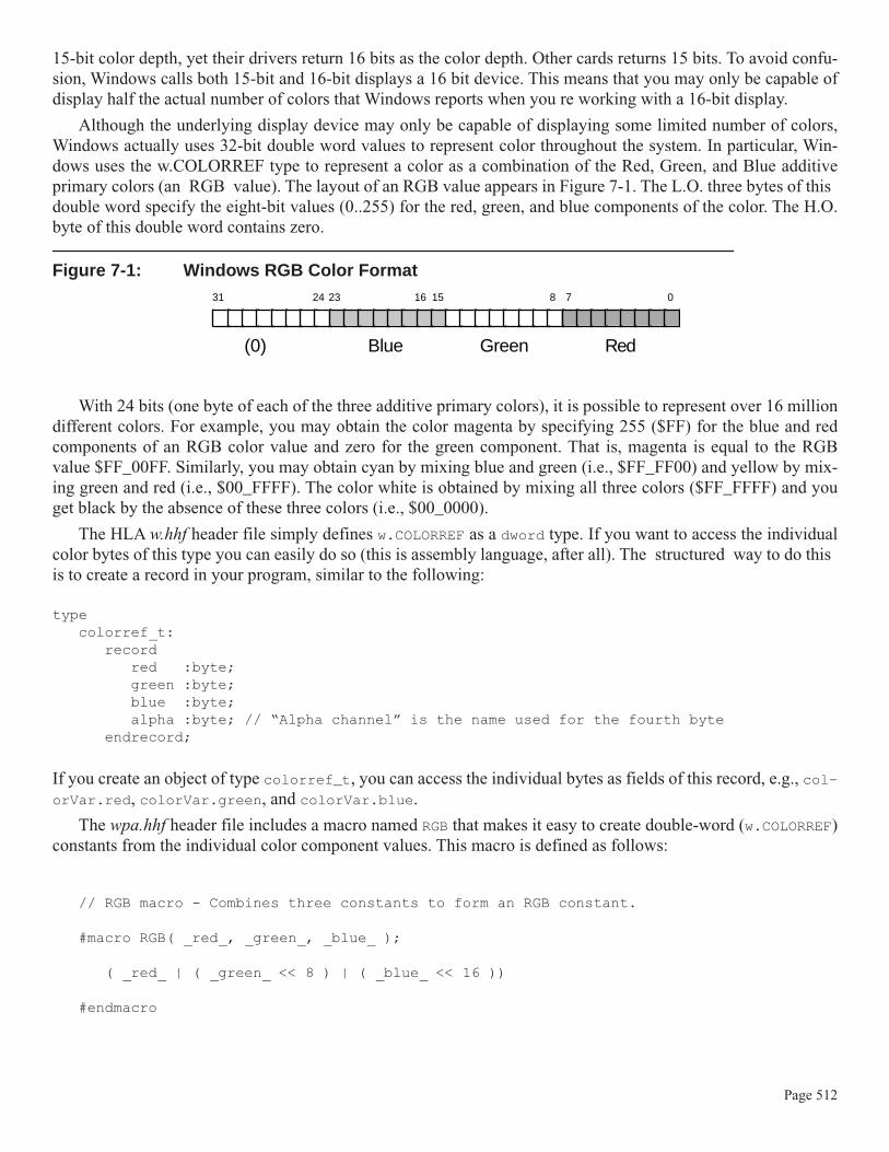
Although the underlying display device may only be capable of displaying some limited number of colors,Windows actually uses 32-bit double word values to represent color throughout the system. In particular, Win-dows uses the w.COLORREF type to represent a color as a combination of the Red, Green, and Blue additiveprimary colors (an RGB value). The layout of an RGB value appears in Figure 7-1. The L.O. three bytes of thisdouble word specify the eight-bit values (0..255) for the red, green, and blue components of the color. The H.O.byte of this double word contains zero.
Figure 7-1: Windows RGB Color Format
With 24 bits (one byte of each of the three additive primary colors), it is possible to represent over 16 milliondifferent colors. For example, you may obtain the color magenta by specifying 255 ($FF) for the blue and redcomponents of an RGB color value and zero for the green component. That is, magenta is equal to the RGBvalue $FF_00FF. Similarly, you may obtain cyan by mixing blue and green (i.e., $FF_FF00) and yellow by mix-ing green and red (i.e., $00_FFFF). The color white is obtained by mixing all three colors ($FF_FFFF) and youget black by the absence of these three colors (i.e., $00_0000).
The HLA w.hhf header file simply defines w.COLORREF as a dword type. If you want to access the individualcolor bytes of this type you can easily do so (this is assembly language, after all). The structured way to do thisis to create a record in your program, similar to the following:
typecolorref_t:
recordred :byte;green :byte;blue :byte;alpha :byte; // “Alpha channel” is the name used for the fourth byte
endrecord;
If you create an object of type colorref_t, you can access the individual bytes as fields of this record, e.g., col-orVar.red, colorVar.green, and colorVar.blue.
The wpa.hhf header file includes a macro named RGB that makes it easy to create double-word (w.COLORREF)constants from the individual color component values. This macro is defined as follows:
// RGB macro - Combines three constants to form an RGB constant.
#macro RGB( _red_, _green_, _blue_ );
( _red_ | ( _green_ << 8 ) | ( _blue_ << 16 ))
#endmacro
08 71516232431
RedGreenBlue(0)
Page 512

One very important thing to note about this macro is that its parameters must all be constants and it returns a con-stant value as its result . You use this macro as the operand of some other instruction or assembler directive, youdo not use this macro as though it were a function. Here s a typical use that defines the color magenta as a sym-bol in the const section of an HLA program:
constmagenta :w.COLORREF := RGB( $FF, $00, $FF );
Again, and this is very important, the RGB operands must all be constants. You may not supply register or mem-ory variables as arguments to this macro. If you would like a generic function that computes RGB values fromeight-bit constants, registers, or memory locations, you could write a macro like the following:
// mkRGB - converts three eight-bit color values into an RGB value:
#macro mkRGB( _red_, _green_, _blue_ );movzx( _blue_, eax );shl( 16, eax );mov( _green_, ah );mov( _red_, al );
#endmacro...mkRGB( redByteVar, $f0, bl ); // RGB value is left in EAX.
Although Windows works with 24-bit color values throughout the system, not all display adapters are capa-ble of displaying this many colors on the screen simultaneously (or, the user may have selected a smaller numberof characters for Windows to use when accessing the display card). As a result, the fact that you ve specified a24-bit color value does not imply that Windows can actually display that color on the screen. To accomodate thisdescrepency, Windows will often use a technique known as dithering to increase the number of available colors.Dithering increases the number of colors by drawing adjacent pixels using different colors that, when blended,approximate the desired color. For example, if you draw an alternating sequence of red and blue pixels, and thenview the result from a distance, the result looks like a solid magenta color. Though dithering increases the maxi-mum number of colors the user perceives on the screen, there are several primary disadvantages of dithering.First, because it takes multiple pixels to do dithering, dithering effectively reduces your screen resolution. Also,dithering only works well when coloring large areas, it doesn t work well for small or thin objects and it doesn twork at all for single pixels. Dithering is fairly obvious when the viewer is close to the video display; the imagelooks coarse and grainy when you apply dithering. Another big disadvantage to dithering is that it is slow - Win-dows has to compute, on the fly, dithering values when it attempts to display a color that the video display modedoesn t directly support. This extra computation can slow down the rendering of some object by a fair amount.
In many cases, applications don t really require an exact color match. For example, some programmer mightwant to display some text with a color that is roughly 25% red and 0% blue and green (that is, a dark red color).Now most video modes are probably capable of displaying an object whose color is 25% red. However, is 25%red represented by the eight-bit value 63 or 64? Pick the wrong one and Windows will attempt to dither the color(producing a low-quality image and running slowly). How do you make sure you pick the pure color that Win-dows can efficiently render? Well, Windows provides a nifty API function that will tell you what the closestpure color is to an RGB value you ve specified: w.GetNearestColor:
static GetNearestColor: procedure
Page 513

( hdc :dword; crColor :dword ); @stdcall; @returns( "eax" ); @external( "__imp__GetNearestColor@8" );
As usual, hdc is the handle of the device context whose color values you wish to check. The crColor parameteris the RGB value whose nearest color you d like to find. This function returns the nearest color in the EAX regis-ter. So if you want to set some color to (approximately) 25% red, you could do this with the following code:
w.GetNearestColor( hDC, RGB( 64, 0, 0 ) ); // 64 is approximately 25% of 255.mov( eax, red25 );
// Now use red25 as the color for 25% red...
Another couple of useful device context values are the Window Origin and Viewport Origin values. The win-dow origin specifies where the logical display s (0,0) point falls in on the display device (the viewport). Theviewport origin specifies where the physical screen s (0,0) point falls in the logical window. These two originvalue provide different views of the same concept - how Windows maps the logical coordinate space to thephysical display coordinate space. An application, should it choose to modify the coordinate systems, would nor-mally modify either the window coordinates or the viewport coordinates, but not both (which would tend to getconfusing). This discussion will center around the use of the Window Origin values but it generally applies to theViewport Origin values as well.
By default, when Windows first opens an application s window, it maps logical coordinate (0,0) on the dis-play to the upper-left hand corner of the physical display device. All coordinates within your application are rel-ative to this mapping. By calling the w.SetWindowOrgEx API function, however, you can tell Windows to mapall coordinate values relative to some other point on the display. For example, you can tell Windows that point(100,100) in your application s coordinate system should correspond to physical point (0,0) on the display. Youmight want to do this, for example, if it s more convenient to work with coordinates in your application that are100 and above. Here are the functions you ll find useful for getting and setting the window origin:
type POINT: record x: dword; y: dword; endrecord;
static
GetWindowOrgEx: procedure ( hdc :dword; var lpPoint :POINT ); @stdcall; @returns( "eax" ); @external( "__imp__GetWindowOrgEx@8" );
SetWindowOrgEx: procedure
Page 514

( hdc :dword; X :dword; Y :dword; var lpPoint :POINT ); @stdcall; @returns( "eax" ); @external( "__imp__SetWindowOrgEx@16" );
The w.GetWindowOrgEx function returns the current window origin for the device context provided by hdc inthe variable you specify via the lpPoint parameter. The w.SetWindowOrgEx function sets the origin for thedevice context you specify via the X and Y parameters and returns the original origin in the lpPoint parameter(this function ignores lpPoint if you pass NULL in this parameter location). The following code fragment, forexample, sets the window origin to (100,100) for use in our hypothetical example given earlier:
w.SetWindowOrgEx( hDC, 100, 100, NULL );
The device context maintains several default drawing objects within the device context. For example, thedefault pen specifies how Windows will draw lines within that context; the default brush specifies how Windowswill fill areas when drawing within the context; the default font specifies how Windows will render text to thedevice, the default colors to use, and so on. We ll discuss how to use the w.SelectObject functions to set thesedefault values a little later in this chapter.
There is a minor problem you ll encounter when using device contexts - you create them in response to anAPI call such as BeginPaint and you destroy the context via a call to an API like EndPaint. Specifically, when-ever you invoke BeginPaint, Windows creates a new device context complete with a set of default values. So ifyou change the default color Windows uses to display text, Windows will forget your change when you callEndPaint to finish the current output operation. This is convenient for certain values, but sometimes you ll wantto set the default device context value that Windows uses. Windows provides an option that lets you tell Win-dows not to reset the device context every time you invoke something like BeginPaint. To do this, you includethe w.CS_OWNDC constant as part of the window class style when creating the window in the first place, e.g.,in an application s main program:
// Set up the window class (wc) object: mov( @size( w.WNDCLASSEX ), wc.cbSize ); mov( w.CS_HREDRAW | w.CS_VREDRAW | w.CS_OWNDC, wc.style ); // Change this line mov( &WndProc, wc.lpfnWndProc ); mov( NULL, wc.cbClsExtra );
.
.
.
With this modification, Windows will allocate a small amount of storage (under 1K) to maintain all the devicecontext values between the EndPaint invocation and the next BeginPaint invocation. So now, for example,when you set the drawing color to red, it will remain red, even across calls to BeginPaint/EndPaint, until youexplicitly change it to something else.
The drawback to using the w.CS_OWNDC style is the fact that Windows will preserve all default values you set,not just one or two that you d like to preserve across BeginPaint/EndPaint invocations. If you need to be ableto change only a few default values but make other changes temporary (i.e., within the bounds of the Begin-
Page 515

Paint/EndPaint sequence), then you ll need some way of preserving the existing device context values andrestoring them later. You can accomplish this with the w.SaveDC and w.RestoreDC calls:
static
SaveDC: procedure ( hdc :dword ); @stdcall; @returns( "eax" ); @external( "__imp__SaveDC@4" );
RestoreDC: procedure ( hdc :dword; nSavedDC :dword ); @stdcall; @returns( "eax" ); @external( "__imp__RestoreDC@8" );
You pass a handle to the device context whose values you want to save or restore to both of these routines. Thew.SaveDC call will save a copy of the device context s values internal to Windows and return a handle by whichyou can restore those values in the EAX register. The w.RestoreDC function uses this handle returned byw.SaveDC as the second parameter to tell Windows which internal values to restore. To use these functions you dtypically write code like the following:
BeginPaint( hdc );
<< code that changes device context values that you want to keep as the default>>
w.SaveDC( hdc );mov( eax, SavedDCHandle ); // Save for later...
<< code that makes temporary changes to the device context >>
w.RestoreDC( hdc, SavedDChandle ); // Restore the values we’ve changed
EndPaint;
Note that w.SaveDC pushes a copy of the current context values onto a stack and w.RestoreDC pops the val-ues off of that stack. The handle that w.SaveDC returns can be thought of as the saved context stack pointer.Therefore, if you call w.SaveDC multiple times without calling w.RestoreDC inbetween, each context is writtento a separate section of memory (i.e., a new entry on the stack). You may pop the last entry pushed via the callw.RestoreDC( hdc, -1 ); This spares having to actually save the return value from w.SaveDC if you usew.SaveDC and w.RestoreDC in a stack like fashion. Note, however, that if you save two contexts on the stack andsave the two handles that w.SaveDC returns, and then you pass the first (earliest) handle that w.SaveDC returns tow.RestoreDC, the w.RestoreDC function pops both contexts off the stack, you cannot restore a later-pushed-con-text after restoring an earlier-pushed-context.
Page 516

As mentioned a little bit earlier, we ll return to the discussion of how to set certain device context values atappropriate moments in this chapter. In the meantime, however, it s time to begin discussing how to actuallydraw things into a device context (i.e., onto the screen).
7.6: Line Drawing Under Windows
Line drawing under Windows is accomplished using five different routines: w.MoveToEx, w.LineTo,
w.PolyLine, w.PolyLineTo, and w.PolyPolyLine. Here are the prototypes for these five functions:
type POINT: record x: dword; y: dword; endrecord;
static
LineTo: procedure ( hdc :dword; nXEnd :dword; nYEnd :dword ); @stdcall; @returns( "eax" ); @external( "__imp__LineTo@12" );
MoveToEx: procedure ( hdc :dword; X :dword; Y :dword; var lpPoint :POINT ); @stdcall; @returns( "eax" ); @external( "__imp__MoveToEx@16" );
Polyline: procedure ( hdc :dword; var lppt :POINT; cPoints :dword ); @stdcall; @returns( "eax" ); @external( "__imp__Polyline@12" );
PolylineTo: procedure ( hdc :dword; var lppt :POINT; cCount :dword
Page 517

); @stdcall; @returns( "eax" ); @external( "__imp__PolylineTo@12" );
PolyPolyline: procedure ( hdc :dword; var lppt :POINT; var lpdwPolyPoints :var; cCount :dword ); @stdcall; @returns( "eax" ); @external( "__imp__PolyPolyline@16" );
All of these functions exist as keyword macros in the BeginPaint/EndPaint multi-part macros. You invokethese macros between the BeginPaint/EndPaint pair; they have the following declarations:
#keyword LineTo( _x_, _y_ ); #keyword MoveToEx( _x_, _y_, _lpPoint_ ); #keyword Polyline( _lppt_, _cPoints_ ); #keyword PolylineTo( _lppt_, _cPoints_ ); #keyword PolyPolylineTo( _lppt_, _lpdwPolyPoints_, _cCount_ );
The invocation sequence is similar to the Win32 API functions except you don t need the w. prefix and youdon t supply the hdc (first) parameter.
The unusual thing about Windows line drawing routines is that most of them make use of the current penposition maintained in the device context. For example, consider the LineTo function that draws a line in thewindow specified by the hdc parameter to BeginPaint. You ll notice that this function has only two parameters,an x-coordinate value and a y-coordinate value; lines, however, are defined by two endpoints, not a single point.The LineTo API function will actually draw a line from the current point (that the device context maintains) tothe point specified by the (x,y) coordinate value you pass to LineTo. After drawing the line, the LineTo functionsets the internal current point value to the endpoint of the line (that is, the (x,y) coordinate we pass LineTo
becomes the new current point after the line is drawn). This feature makes it very easy to draw complex con-nected shapes as a sequence of connected lines by making sequential calls to LineTo.
There are two problems with LineTo s behavior; specifically, how do we set the initial starting point? andwhat happens when we want to draw two unconnected line segments? Well, the MoveToEx macro comes to our
rescue in this case. The MoveToEx macro (i.e., w.MoveToEx API function) sets the current point inside thedevice context but has no other effect on the display. You can use this function to set the initial endpoint of a lineand then call LineTo to draw the line from that point to the line s end point, e.g.,
// Draw a line from (10, 10) to (100, 50):
MoveToEx( 10, 10, NULL );LineTo( 100, 50 );
The third parameter in the MoveToEx invocation specifies a variable of type w.POINT where Windows willstore the device context s current point value. If this argument is NULL (as in this example), then Windowswill not bother storing the value.
Page 518

Because drawing a complex object as a sequence of line segments is so common, the operation of the Move-ToEx and LineTo functions is just what you want a large percentage of the time. However, if you decide to drawa fairly complex object made up of dozens, hundreds, or even thousands of line segments, the calls to LineTo canbecome a performance bottleneck,. The problem is that many modern display adapters provide hardware acceler-ation of various graphic primitives (including line drawing). As a result of this acceleration, the system actuallywinds up spending more time calling the LineTo function than actually drawing the line. To reduce the overheadof the LineTo function invocations when drawing objects made up of complex line segments, Windows providesthe Polyline, PolylineTo, and PolyPolylineTo functions. These functions take an array of points (or an arrayof polylines, that is, an array of array of points) and pass that data on down to the GDI driver that is responsiblefor drawing lines. The line drawing code can quickly draw the sequence of line segments without the overhead ofmultiple calls to the line drawing function.
The execution of the PolylineTo function is roughly equivalent to a sequence of LineTo calls. It beginsdrawing line segments from the current position to the first point in an array of points you pass to this function.PolylineTo sets the current position to the coordinate of the last point appearing in the array of points. Thelppt parameter is a pointer to an array of w.POINT records and the cCount parameter specifies the number ofpoints in that array.
The Polyline and PolyPolyline functions neither use nor modify the current pen position value in thedevice context. The Polyline function (to which you pass an array of points and a count) draws a sequence oflines starting with the first point in the list through each of the remaining points in the list. We ll take a look at anexample of a Polyline call a little later in this section. The PolyPolyline API function accepts an array ofpolylines and draws the object specified by all these points.
When drawing lines, Windows uses several default values in the device context to control how the line isdrawn. This includes the color of the line, the width of the line, and the line s style (e.g., solid, dotted, dashed,etc.). The default pen setting is a black, solid pen whose width is one pixel. While this is probably the most com-mon line style you will draw, there is often the need to draw lines of a different color, a different width, or withsome other style besides solid. In order to do this, you must create a new pen and select that pen into the currentdevice context. To create a new pen, you use the Windows w.CreatePen API call. Here s the prototype for thatfunction:
static
CreatePen: procedure ( fnPenStyle :dword; nWidth :dword; crColor :COLORREF ); @stdcall; @returns( "eax" ); @external( "__imp__CreatePen@12" );
The fnPenStyle parameter specifies a style for the pen. This can be one of the values that Table 7-2 describes.The use of most of these constants is fairly self-explanatory. We ll discuss the purpose of thew.PS_INSIDEFRAME pen style in a later section of this chapter.
Page 519

Table 7-2: Pen Styles
The w.CreatePen nWidth parameter is only valid for the w.PS_SOLID, w.PS_NULL, andw.PS_INSIDEFRAME pen styles. This specifies the width of the line in logical device units. If this field containszero, the width of the line is always one pixel (which isn t necessarily true if the nWidth value is one).
The crColor parameter is an RGB value that specifies the color that the pen will draw on the screen. Notethat you can use the wpa.hhf RGB macro to create an RGB value to pass as this parameter.
When you call w.CreatePen, Windows will create a pen GDI object internally and return a handle to that penin the EAX register. Note that Windows does not automatically start using this pen. You must select this pen intothe device context if you want to use it while drawing lines. This is done with the w.SelectObject API function(or SelectObject #keyword macro found in the wpa.hhf header file). When you select a pen into the currentdevice context via SelectObject, Windows returns the handle to the previous pen that was selected. You cansave this former pen value in order to restore the original pen when you are done using the current pen, e.g.,
BeginPaint( hwnd, ps, hdc );...
w.CreatePen( w.PS_SOLID, 0, RGB( $FF, $00, $FF )); // Solid, magenta, pen.mov( eax, magentaPen ); // Save, so we can delete later.SelectPen( eax ); // Select the magenta pen into the context.mov( eax, oldPen ); // Save, so we can restore.
.
.
.SelectPen( oldPen ); // Restore original pen.w.DeleteObject( magentaPen );
Pen Style Description
w.PS_SOLID Draw a solid line with the pen.
w.PS_DASH The pen is dashed. This style is valid only when the pen width is one or less in device units.
w.PS_DOT The pen is dotted. This style is valid only when the pen width is one or less in device units.
w.PS_DASHDOT The pen has alternating dashes and dots. This style is valid only when the pen width is one or less in device units.
w.PS_DASHDOTDOT The pen has alternating dashes and double dots. This style is valid only when the pen width is one or less in device units.
w.PS_NULL Windows does not draw with the pen.
w.PS_INSIDEFRAME The pen is solid. When this pen is used in any GDI drawingfunction that takes a bounding rectangle, the dimensions of thefigure are shrunk so that it fits entirely within the bounding rectangle,taking into account the width of the pen.
Page 520

EndPaint;
Although this example might suggest this to be the case, understand that pens you create via w.CreatePenare not part of the device context. That is, you can create a pen outside the BeginPaint/EndPaint sequence andsuch pen values are persistent outside of the BeginPaint/EndPaint sequence. The calls to w.CreatePen andw.DeletePen appear inside the BeginPaint/EndPaint sequence here mainly for typographical convenience.Their presence in this sequence does not imply that these calls have to take place inside this sequence.
Because the w.CreatePen API function creates a resource inside Windows, you must be sure to delete thatpen when you are done using it via a call to w.DeletePen. Because Windows has limited GDI resources avail-able, failure to delete any GDI resources your program uses may lead to resource leak which will impact theoverall system performance. Though you don t have to create and destroy a GDI object within your Paint proce-dure, you do need to make sure you delete all resources your program creates before your program quits. Manyapplications create the pens they need in their Create procedure and then delete those pens in the QuitApplica-tion procedure. This sequence spares the application from having to constantly create and destroy often-usedpens.
Windows provides three built-in, or stock, pens that you can use without calling w.CreatePen to create them:a black pen (the default), a white pen, and a null pen (which doesn t affect the display when you draw with it).You may obtain a handle to any of these stock pens by calling the w.GetStockObject API function:
static GetStockObject: procedure( fnObject:dword ); @stdcall; @returns( "eax" ); @external( "__imp__GetStockObject@4" );
This function requires a special value to tell Windows exactly what kind of object you want to create. The win-dows.hhf header file defines three constants that you can use to tell w.GetStockObject to return a handle to one ofthe stock pens: w.BLACK_PEN, w.WHITE_PEN, and w.NULL_PEN. For example, to quickly obtain the handle for awhite pen, you can use the following call:
w.GetStockObject( w.WHITE_PEN );mov( eax, whitePenHandle );
Note that you must not delete a stock object.
7.6.1: Background Mode and Color for Lines
When using a pen style that involves dashed or dotted lines, Windows uses the current background mode andcolor to determine how to draw the space between the dots and dashes that comprise the line. You can set thebackground color and mode by using the w.SetBkColor and w.SetBkMode API functions, respectively:static
SetBkColor: procedure( hdc:dword; crColor:dword ); @stdcall; @returns( "eax" ); @external( "__imp__SetBkColor@8" );
Page 521

SetBkMode: procedure( hdc:dword; iBkMode:dword ); @stdcall; @returns( "eax" ); @external( "__imp__SetBkMode@8" );
The hdc parameter to these functions is, obviously, the handle of the device context whose background coloror mode you want to change. The crColor parameter to the w.SetBkColor function is an RGB color value thatwindows will use when drawing the gaps (if any) between the lines of an image it is rendering. The iBkModeparameter you supply to w.SetBkMode is either w.OPAQUE or w.TRANSPARENT. If you specify the w.OPAQUEmode, then Windows will fill the gaps in a dotted or dashed line with a solid color, the color you specify with thew.SetBkColor function call. Note that in the opaque mode, Windows overwrites whatever was previously on thescreen using the solid color you ve specified. On the other hand, if you specify w.TRANSPARENT as the back-ground drawing mode, then Windows will ignore the background color and leave whatever image originallylappeared on the screen in the gaps between the dashes and dots of a stylistic line.
7.6.2: Using the LineTo and MoveToEx API Functions
As a demonstration of the line drawing capabilities of Windows, the Lines.hla program repeatedly draws aset of pseudo-random lines on the display. This application is a typical Windows app with two wndproc proce-dures - Paint and Size. The Size procedure tracks window size changes so the Paint procedure can keep alllines within the boundaries of the window. The Paint procedure computes the endpoints of a somewhat ran-dom line to draw and then draws that line to the window.
Because the Size procedure is especially trivial, we ll take a look at it first. This procedure simply copies thevalues for the new width and height into a couple of global variables (ClientSizeX and ClientSizeY). Here sits code:
// Size-//// This procedure handles the w.WM_SIZE message// Basically, it just saves the window's size so// the Paint procedure knows when a line goes out of// bounds.//// L.O. word of lParam contains the new X Size// H.O. word of lParam contains the new Y Size
procedure Size( hwnd: dword; wParam:dword; lParam:dword );begin Size;
// Convert new X size to 32 bits and save:
movzx( (type word lParam), eax );mov( eax, ClientSizeX );
// Convert new Y size to 32 bits and save:
movzx( (type word lParam[2]), eax );mov( eax, ClientSizeY );
xor( eax, eax ); // return success.
Page 522

end Size;
The Paint procedure is a tiny bit more complicated. The first thing to consider are the variables that the Paintprocedure uses to maintain the state of the pseudo-random lines it draws. Here are the declarations:
static hPen :dword; // Pen handle. OldPen :dword; // Old Pen Handle. lastRGB :w.COLORREF; // Last color we used x1 :int32 := 0; y1 :int32 := 0; x2 :int32 := 25; y2 :int32 := 25; lastDeltaX1 :int32 := 1; lastDeltaY1 :int32 := 1; lastDeltaX2 :int32 := 2; lastDeltaY2 :int32 := 2; changeCntr :uns32 := 10;
The hPen variable holds the handle of the new pen this program creates (to control the color of the output);the OldPen variable maintains the handle of the old pen so that Paint can restore the original pen once Paint isfinished drawing with the new pen. The lastRGB variable holds the color of the last pen. Paint increments thisvalue to create a new color for each line it draws to the window. The x1, x2, y1, and y2 variables hold thecoordinates of the end points of the line that Paint draws. The Paint procedure uses the lastDelta** andchangeCntr variables to compute new endpoints for each line it produces. Here s how Paint uses these deltavariables: on each pass through the Paint procedure, the code adds the value of lastDeltaX1 to the x1 variable,it adds lastDeltaY1 to y1, it adds lastDeltaX2 to x2, and it adds lastDeltaY2 to y2. This generates a new setof end points for the line. Should any one of those end points fall outside the boundaries of the screen, the Paintprocedure clips the particular coordinate value so that it remains within the window s boundaries (and Paint alsonegates the corresponding lastDelta** value so that future adjustments continue to stay within the window sboudaries). The changeCntr variable determines how many line segments that Paint will draw with the currentset of lastDelta** values before it chooses some new, semi-random, values for these variables. Here s how thePaint procedure uses changeCntr to determine when to set the lastDelta** values to semi-random values:
// If the changeCntr variable counts down to zero, compute new // delta values:
dec( changeCntr ); if( @z ) then
rand.range( 1, 100 ); // Compute a new, random, value for changeCntr mov( eax, changeCntr );
// Compute new (random) values for the lastDelta** variables:
rand.range( 0, 10 ); // We want a value in the range -5..+5 sub( 5, eax ); mov( eax, lastDeltaX1 );
rand.range( 0, 10 ); sub( 5, eax ); mov( eax, lastDeltaY1 );
Page 523

rand.range( 0, 10 ); sub( 5, eax ); mov( eax, lastDeltaX2 );
rand.range( 0, 10 ); sub( 5, eax ); mov( eax, lastDeltaY2 );
endif;
Here s the code sequence that computes the new x1 value (computations for the x2, y1, and y2 values arenearly identical):
// Compute a new starting X-coordinate for the // line we're about to draw (do this by adding // the appropriate delta to our current x-coordinate // value):
mov( lastDeltaX1, eax ); add( x1, eax ); if( @s ) then
// If we went off the left edge of the window, // then change the direction of travel for the // deltaX value:
neg( lastDeltaX1 ); add( lastDeltaX1, eax );
endif;
// Check to see if we went off the right edge of the window. // Reset the direction of deltaX if this happens:
if( eax > ClientSizeX ) then
neg( lastDeltaX1 ); mov( ClientSizeX, eax ); dec( eax );
endif; mov( eax, x1 );
Note that on one pass through the Paint procedure this code draws only a single line segment.
Because the Paint procedure draws only a single line segment in response to a w.WM_PAINT message, ittakes a continuous stream of w.WM_PAINT messages in order to generate the free-running display that Lines.hlaproduces in its window. The real trick to Lines.hla is how it continuously draws these line segments in its win-dow. We can t stick an HLA forever loop inside our Paint procedure to continuously draw a sequence of linesover and over again; if we did that, the program wouldn t respond to messages and there would be no way toquite this program except by running the Windows task manager and killing the process. Because this is some-what ill-behaved for an application, we ve got to dream up a better way of telling the application to continuouslydraw lines. One sneaky way to do this is to tell Windows to send our application a w.WM_PAINT message justbefore leaving the Paint procedure. This action, of course, will cause Windows to call our Paint procedure
Page 524

again in short order, but through the standard message handling subsystem so our application can still respond tow.WM_DESTROY messages. The correct way to tell Windows to send our application a w.WM_PAINT message is tocall the w.InvalidateRect API function, passing it a NULL rectangle to invalidate (which tells it to invalidatethe whole window). Here s the call that does this (which appears at the end of the Paint procedure):
w.InvalidateRect( hwnd, NULL, false );
The last argument in the w.InvalidateRect parameter list tells this function to whether it should erase thescreen before having Paint redraw it. Because we want to keep all the previous lines we ve drawn in the window,this call passes false as the value of this parameter.
Here s the complete listing of the Lines.hla program:
// Lines.hla-//// Simple Application the demonstrates line drawing.
program Lines;#include( "rand.hhf" )#include( "hll.hhf" )#include( "w.hhf" )#include( "wpa.hhf" )
?@NoDisplay := true;?@NoStackAlign := true;
type // Message and dispatch table related definitions: MsgProc_t: procedure( hwnd:dword; wParam:dword; lParam:dword ); MsgProcPtr_t: record MessageValue :dword; MessageHndlr :MsgProc_t; endrecord;
static hInstance :dword; // "Instance Handle" Windows supplies.
wc :w.WNDCLASSEX; // Our "window class" data. msg :w.MSG; // Windows messages go here. hwnd :dword; // Handle to our window. ClientSizeX :int32 := 0; // Size of the client area ClientSizeY :int32 := 0; // where we can paint. readonly
Page 525

ClassName :string := "LinesWinClass"; // Window Class Name AppCaption :string := "Lines Program"; // Caption for Window
// The dispatch table: // // This table is where you add new messages and message handlers // to the program. Each entry in the table must be a MsgProcPtr_t // record containing two entries: the message value (a constant, // typically one of the w.WM_***** constants found in windows.hhf) // and a pointer to a "MsgProcPtr_t" procedure that will handle the // message. Dispatch :MsgProcPtr_t; @nostorage;
MsgProcPtr_t MsgProcPtr_t:[ w.WM_DESTROY, &QuitApplication ], MsgProcPtr_t:[ w.WM_PAINT, &Paint ], MsgProcPtr_t:[ w.WM_SIZE, &Size ], // Insert new message handler records here. MsgProcPtr_t:[ 0, NULL ]; // This marks the end of the list. /**************************************************************************//* A P P L I C A T I O N S P E C I F I C C O D E *//**************************************************************************/
// QuitApplication://// This procedure handles the w.WM_DESTROY message.// It tells the application to terminate. This code sends// the appropriate message to the main program's message loop// that will cause the application to terminate. procedure QuitApplication( hwnd: dword; wParam:dword; lParam:dword );begin QuitApplication;
w.PostQuitMessage( 0 );
end QuitApplication;
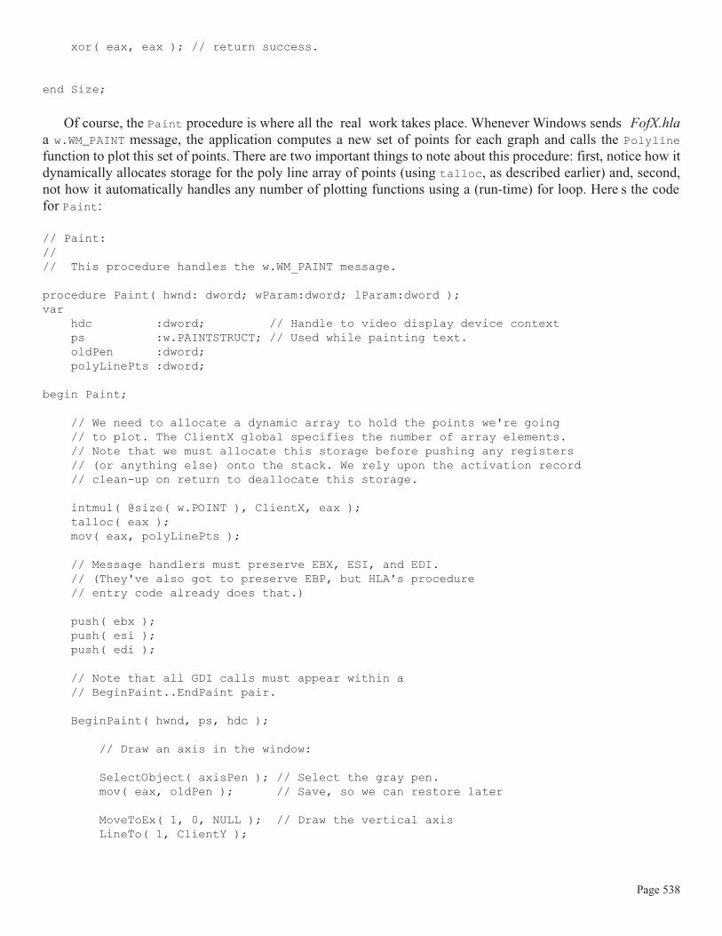
// Paint://// This procedure handles the w.WM_PAINT message.
procedure Paint( hwnd: dword; wParam:dword; lParam:dword );var hdc :dword; // Handle to video display device context
Page 526

ps :w.PAINTSTRUCT; // Used while painting text.
static hPen :dword; // Pen handle. OldPen :dword; // Old Pen Handle. lastRGB :w.COLORREF; // Last color we used x1 :int32 := 0; y1 :int32 := 0; x2 :int32 := 25; y2 :int32 := 25; lastDeltaX1 :int32 := 1; lastDeltaY1 :int32 := 1; lastDeltaX2 :int32 := 2; lastDeltaY2 :int32 := 2; changeCntr :uns32 := 10;
begin Paint;
// Message handlers must preserve EBX, ESI, and EDI. // (They've also got to preserve EBP, but HLA's procedure // entry code already does that.) push( ebx ); push( esi ); push( edi ); // Note that all GDI calls must appear within a // BeginPaint..EndPaint pair. BeginPaint( hwnd, ps, hdc );
inc( lastRGB ); // Increment the color we're using.
// If the changeCntr variable counts down to zero, compute new // delta values:
dec( changeCntr ); if( @z ) then
rand.range( 1, 100 ); mov( eax, changeCntr );
// Compute new (random) values for the lastDelta* variables:
rand.range( 1, 10 ); sub( 5, eax ); mov( eax, lastDeltaX1 );
rand.range( 1, 10 ); sub( 5, eax ); mov( eax, lastDeltaY1 );
rand.range( 1, 10 ); sub( 5, eax ); mov( eax, lastDeltaX2 );
rand.range( 1, 10 );
Page 527

sub( 5, eax ); mov( eax, lastDeltaY2 );
endif; // Compute a new starting X-coordinate for the // line we're about to draw (do this by adding // the appropriate delta to our current x-coordinate // value):
mov( lastDeltaX1, eax ); add( x1, eax ); if( @s ) then
// If we went off the left edge of the window, // then change the direction of travel for the // deltaX value:
neg( lastDeltaX1 ); add( lastDeltaX1, eax );
endif;
// Check to see if we went off the right edge of the window. // Reset the direction of deltaX if this happens:
if( eax > ClientSizeX ) then
neg( lastDeltaX1 ); mov( ClientSizeX, eax ); dec( eax );
endif; mov( eax, x1 ); // Same as the above code, except for the Y coordinate
mov( lastDeltaY1, eax ); add( y1, eax ); if( @s ) then
neg( lastDeltaY1 ); add( lastDeltaY1, eax );
endif; if( eax > ClientSizeY ) then
neg( lastDeltaY1 ); mov( ClientSizeY, eax ); dec( eax );
endif; mov( eax, y1 );
// Same as all the above code, but for the end point // (rather than the starting point) of the line:
Page 528
mov( lastDeltaX2, eax ); add( x2, eax ); if( @s ) then
neg( lastDeltaX2 ); add( lastDeltaX2, eax );
endif; if( eax > ClientSizeX ) then
neg( lastDeltaX2 ); mov( ClientSizeX, eax ); dec( eax );
endif; mov( eax, x2 ); mov( lastDeltaY2, eax ); add( y2, eax ); if( @s ) then
neg( lastDeltaY2 ); add( lastDeltaY2, eax );
endif; if( eax > ClientSizeY ) then
neg( lastDeltaY2 ); mov( ClientSizeY, eax ); dec( eax );
endif; mov( eax, y2 );
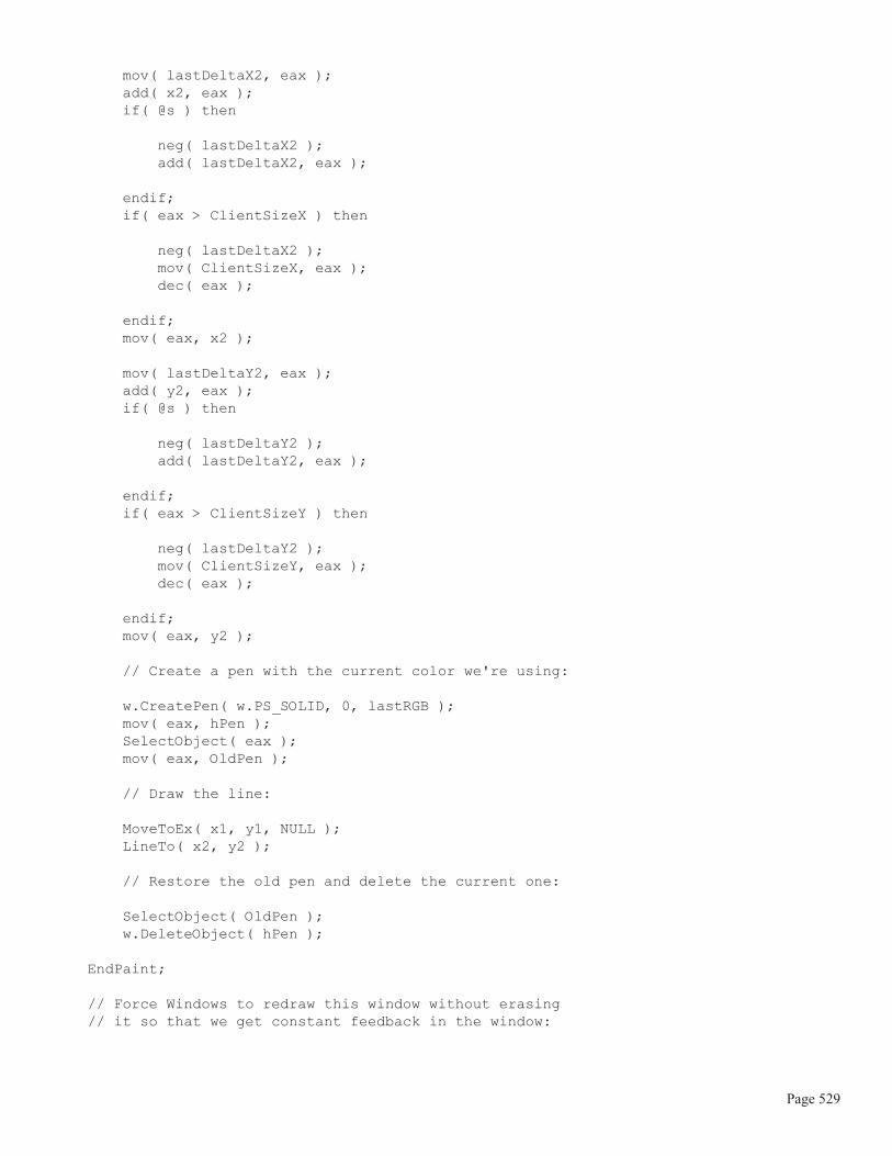
// Create a pen with the current color we're using:
w.CreatePen( w.PS_SOLID, 0, lastRGB ); mov( eax, hPen ); SelectObject( eax ); mov( eax, OldPen ); // Draw the line:
MoveToEx( x1, y1, NULL ); LineTo( x2, y2 ); // Restore the old pen and delete the current one:
SelectObject( OldPen ); w.DeleteObject( hPen ); EndPaint;
// Force Windows to redraw this window without erasing // it so that we get constant feedback in the window:
Page 529

w.InvalidateRect( hwnd, NULL, false ); pop( edi ); pop( esi ); pop( ebx );
end Paint;
// Size-//// This procedure handles the w.WM_SIZE message// Basically, it just saves the window's size so// the Paint procedure knows when a line goes out of// bounds.//// L.O. word of lParam contains the new X Size// H.O. word of lParam contains the new Y Size
procedure Size( hwnd: dword; wParam:dword; lParam:dword );begin Size;
// Convert new X size to 32 bits and save:
movzx( (type word lParam), eax ); mov( eax, ClientSizeX );
// Convert new Y size to 32 bits and save:
movzx( (type word lParam[2]), eax ); mov( eax, ClientSizeY ); xor( eax, eax ); // return success.
end Size;
/**************************************************************************//* End of Application Specific Code *//**************************************************************************/
// The window procedure. // This is actually a function that returns a return result in// EAX. If this function returns zero in EAX, then the event// loop terminates program execution.
procedure WndProc( hwnd:dword; uMsg:uns32; wParam:dword; lParam:dword ); @stdcall;
begin WndProc;
Page 530

// uMsg contains the current message Windows is passing along to // us. Scan through the "Dispatch" table searching for a handler // for this message. If we find one, then call the associated // handler procedure. If we don't have a specific handler for this // message, then call the default window procedure handler function. mov( uMsg, eax ); mov( &Dispatch, edx ); forever mov( (type MsgProcPtr_t [edx]).MessageHndlr, ecx ); if( ecx = 0 ) then // If an unhandled message comes along, // let the default window handler process the // message. Whatever (non-zero) value this function // returns is the return result passed on to the // event loop. w.DefWindowProc( hwnd, uMsg, wParam, lParam ); exit WndProc; elseif( eax = (type MsgProcPtr_t [edx]).MessageValue ) then // If the current message matches one of the values // in the message dispatch table, then call the // appropriate routine. Note that the routine address // is still in ECX from the test above. push( hwnd ); // (type tMsgProc ecx)(hwnd, wParam, lParam) push( wParam ); // This calls the associated routine after push( lParam ); // pushing the necessary parameters. call( ecx ); sub( eax, eax ); // Return value for function is zero. break; endif; add( @size( MsgProcPtr_t ), edx ); endfor; end WndProc;
// Here's the main program for the application. begin Lines;
// Get this process' handle: w.GetModuleHandle( NULL ); mov( eax, hInstance );
Page 531

// Set up the window class (wc) object: mov( @size( w.WNDCLASSEX ), wc.cbSize ); mov( w.CS_HREDRAW | w.CS_VREDRAW, wc.style ); mov( &WndProc, wc.lpfnWndProc ); mov( NULL, wc.cbClsExtra ); mov( NULL, wc.cbWndExtra ); mov( w.COLOR_WINDOW+1, wc.hbrBackground ); mov( NULL, wc.lpszMenuName ); mov( ClassName, wc.lpszClassName ); mov( hInstance, wc.hInstance ); // Get the icons and cursor for this application: w.LoadIcon( NULL, val w.IDI_APPLICATION ); mov( eax, wc.hIcon ); mov( eax, wc.hIconSm ); w.LoadCursor( NULL, val w.IDC_ARROW ); mov( eax, wc.hCursor ); // Okay, register this window with Windows so it // will start passing messages our way. Once this // is accomplished, create the window and display it. w.RegisterClassEx( wc );
w.CreateWindowEx ( NULL, ClassName, AppCaption, w.WS_OVERLAPPEDWINDOW | w.WS_VSCROLL | w.WS_HSCROLL, w.CW_USEDEFAULT, w.CW_USEDEFAULT, w.CW_USEDEFAULT, w.CW_USEDEFAULT, NULL, NULL, hInstance, NULL ); mov( eax, hwnd ); w.ShowWindow( hwnd, w.SW_SHOWNORMAL ); w.UpdateWindow( hwnd ); // Here's the event loop that processes messages // sent to our window. On return from GetMessage, // break if EAX contains false and then quit the // program. forever w.GetMessage( msg, NULL, 0, 0 ); breakif( !eax );
Page 532

w.TranslateMessage( msg ); w.DispatchMessage( msg ); endfor;
// The message handling inside Windows has stored // the program's return code in the wParam field // of the message. Extract this and return it // as the program's return code. mov( msg.wParam, eax ); w.ExitProcess( eax ); end Lines;
7.6.3: Using the PolyLineTo API Function
The PolylineTo (and Polyline and PolyPolyline) functions provide a high-performance way to draw alarge number of connected line sequences. At first glance it might appear that these functions are useful on occa-sion but don t have a tremendous amount of utility - after all, how many different objects can you draw with asequence of connected straight lines? However, such an attitude is a bit naive. It turns out that these poly linefunctions are great for drawing arbitrary curves. It might not seem reasonable to draw arbitrary curves usingstraight lines, but keep in mind that if the line segments are short enough, the fact that a curve is built up ofstraight lines won t be noticable. In this section we ll explore this fact by writing a function that graphs a set ofarbitrary functions.
The basic premise for the function plotting program is that we ll compute the values for some function y=f(x)with x ranging over some reasonable (though closely spaced) set of values. By feeding this function a set ofmonotonically increasing values along the x axis and then drawing a line betwen the last (x,y) pair produced andthe current (x,y) produced, we can obtain a plot of that function. By spacing the x values close together, we canproduce a finely detailed plot and it won t be at all apparent that the curves in that plot are made up of straightline segments.
The FtoX.hla program actually plots several functions simultaneously in the window. To differentiate theplots for each of the different functions, this program uses a different pen (and color) for each of the graphs. Thisparticular program plots the graphs for the sine, cosine, log, and tangent functions. Because the sine and cosinefunctions return a value between -1.0 and +1.0, this function scales their values so that they fit within the middle80% of the window. Because the log function produces values that are completely out of range, this programclips out of range values. Note that the graphs for each of these functions do not use the same scaling functions -the intent is to draw a pretty picture and demonstrate the use of the PolyLine function, not provide a mathemati-cally correct image.
These functions create one line segment for each pixel along the x-axis. To plot the graph of one of thesefunctions the program runs a for loop from zero to the width of the window (incrementing by one) and passesthe loop index to one of the functions as the value for x in the function y=f(x), with f being sine, cosine, tangent,or log. The functions return a value between zero and the current window s height. The Paint procedure (thatcontains this for loop) saves the (x,y) pair as the next line end point to plot for that function.
In order to save all these (x,y) end points, the Paint procedure needs an array of w.POINT values for each ofthe functions (that is, a polyline data structure). Because the user can resize the window at any time, we cannotdeetermine the size of this array at compile time. The number of elements in these arrays is going to be a functionof the window s size at run-time. While we could do something really gross like overallocate storage for the
Page 533
arrays (i.e., make them so large that we don t have to worry about overrunning their bounds), the correct way todeal with arrays of this form is to dynamically allocate their storage at run-time based on the exact number of ele-ments we need.
Because we only need these arrays for the duration of Paint’s execution, allocating the storage for thesearrays using malloc, or using HLAs dynamic array library, is almost as disgusting as over-allocating storage forthe arrays. Dynamic allocation is not particularly fast, even if it is memory efficient. A better solution is to simplyallocate storage for the dynamic arrays on the stack so that the storage is automatically deallocated when thePaint procedure returns to Windows. We can reserve storage on the stack using the HLA Standard Library tal-loc function. You pass this function a block size and it returns a pointer to a block of memory at least that largein the EAX register. This function allocates that storage on the stack.
Warning: talloc allocates its storage by dropping the stack down by some number of bytes(possibly larger than you ve requested, to keep the stack double-word aligned). This means that ifyou ve recently pushed data onto the stack, you ll not be able to access that data unless you vesaved a pointer to that data on the stack. Exiting from the Paint procedure will automaticallydeallocate this storage, but anything you ve pushed onto the stack before allocation may becomeinaccessible. Therefore, it s a good idea to allocate storage with talloc before pushing registersor other values on the stack in the Paint procedure.
The Size procedure in the FofX.hla program tracks any changes to the window s size (including the originalwindow creation) and stores the width and height in the global ClientX and ClientY variables. Upon entry intothe Paint procedure, the program can allocate sufficient storage to hold the end points Polyline must draw.
Although this program only plots four different functions, the number of functions is not hard-coded into thePaint procedure. Instead, this application uses an array of pens, and array of procedure pointers, and an array ofpointers to the endpoint array data to make it very easy to change the number of functions that this program han-dles. By simply changing a constant at the beginning of the source file and adding (or removing) an appropriatemathematical function, you can easily change this program to plot additional (or fewer) functions without amajor rewrite of the code. The numFuncs constant declaration controls the number of functions this applicationwill plot:
// The following constant defintion defines how many functions we're going// to plot with this program:
constnumFuncs := 4;
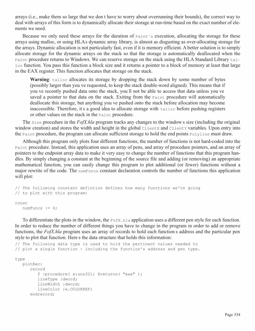
To differentiate the plots in the window, the FofX.hla application uses a different pen style for each function.In order to reduce the number of different things you have to change in the program in order to add or removefunctions, the FofX.hla program uses an array of records to hold each function s address and the particular penstyle to plot that function. Here s the data structure that holds this information:// The following data type is used to hold the pertinent values needed to// plot a single function - including the function's address and pen type.
typeplotRec:
recordf :procedure( x:uns32); @returns( "eax" );lineType :dword;lineWidth :dword;lineColor :w.COLORREF;
endrecord;
Page 534

// The following table has one entry for each of the functions we're// going to plot. It specifies the function to call and the pen info.// The number of entries in this table must match the numFuncs constant// value (this table must be maintained manually!).
readonlyplotInfo : plotRec[ numFuncs ] :=
[plotRec:[ &sin, w.PS_SOLID, 0, RGB( $F0, $70, $F0) ],plotRec:[ &cos, w.PS_SOLID, 0, RGB( $00, $C0, $C0) ],plotRec:[ &tan, w.PS_SOLID, 0, RGB( $C0, $C0, $00) ],plotRec:[ &log, w.PS_SOLID, 0, RGB( $FF, $C0, $80) ]
];
To add a new function to plot, you would add a new entry to the plotInfo array that provides the address of thefunction and the pen style, width, and color values (of course, you need to supply the actual function as well).These are the three changes you need to make in order to plot a new function: change the value of the numFuncsconstant, add an entry to the plotInfo array, and then write the actual function that computes y=f(x) for a givenvalue of x.
The individual functions take a single integer parameter and return an integer result in the EAX register.When computing the data to plot, the FofX.hla program sequences through each of the x-coordinate values in thewindow and passes these values to the individual functions; whatever values they return, the FofX.hla programuses as the corresponding y-coordinate of the next point to plot. Here is a typical example - the sin functioncomputes the sin of the angle (in degrees) passed in as the parameter and returns a scaled y-coordinate value (toplot the sin curve such that it fills the window):// sin- plots the sine of the angle (in degrees) passed as the parameter:
procedure sin( x:uns32 ); @returns( "eax" );var WinHt :uns32;begin sin;
// Note: fsin wants radians, so convert x to radians as // radians = degrees*pi/180:
fild( x ); fld( 180.0 ); fdiv(); fldpi(); fmul();
// Compute the sine of the angle:
fsin(); // Sine produces a result between -1..+1, scale to within 90% of // the top and bottom of our window:
mov( ClientY, eax ); shr( 1, eax ); mov( eax, WinHt ); fild( WinHt ); fmul();
Page 535

fld( 0.9 ); fmul(); fild( WinHt ); fadd();
// Return an integer result as our Y-axis value:
fistp( WinHt ); mov( WinHt, eax );
end sin;
The remaining functions compute similar results. The cos function computes the cosine, the tan function com-putes the trigonmetric tangent, and the log function computes a combination logarithm/sine function (log byitself is a rather boring curve, combining log and sine produces something a bit more interesting). See the pro-gram listing a little later for the exact implementation of these functions.
When the FofX.hla application plots each of the curves for the numFuncs functions, it uses a different colorfor each plot in order to make it easier to differentiate the different graphs in the window. This means that theprogram needs to create a different pen object for each graph it draws. Athough the program could create (anddestroy) these pens on the fly, this application actually creates an array of pen objects and initializes this array inthe Create procedure and then destroys each of these pens in the QuitApplication procedure. Here s the perti-nent code to deal with these pens:
static pens :dword[ numFuncs ]; // Pens used for each plot. axisPen :dword;
// The Create procedure creates all the pens we're going to use// in this application to plot the various functions
procedure Create( hwnd: dword; wParam:dword; lParam:dword );begin Create;
// Create pens for each of the functions:
#for( i := 0 to numFuncs-1 )
w.CreatePen ( plotInfo.lineType [ i*@size( plotRec ) ], plotInfo.lineWidth[ i*@size( plotRec ) ], plotInfo.lineColor[ i*@size( plotRec ) ] ); mov( eax, pens[ i*4 ] );
#endfor
// Create a thicker, gray, pen for drawing the axis:
w.CreatePen( w.PS_SOLID, 2, RGB( $20, $20, $20) ); mov( eax, axisPen );
end Create;
Page 536

// QuitApplication://// This procedure handles the w.WM_DESTROY message.// It tells the application to terminate. This code sends// the appropriate message to the main program's message loop// that will cause the application to terminate. procedure QuitApplication( hwnd: dword; wParam:dword; lParam:dword );begin QuitApplication;
// Delete the pens we created in the Create procedure:
#for( i := 0 to numFuncs-1 )
w.DeleteObject( pens[ i*4 ] );
#endfor w.DeleteObject( axisPen );
w.PostQuitMessage( 0 );
end QuitApplication;
Note how the Create and QuitApplication procedures use a compile-time loop to automatically generate allthe code needed to initialize numFuncs pens so that you don t have to change these procedures should you everdecide to add or remove functions that this program plots.
The FofX.hla program redraws its window everytime you resize the window. Of course, resizing means thatthe program has more (or less) window space to draw, so the program has to keep track of the window s sizewhen a redraw actually occurs. FofX.hla does this by saving the window s width and height values passed alongwith the w.WM_SIZE message that Windows sends along whenever the user resizes the screen:
// Size-//// This procedure handles the w.WM_SIZE message// Basically, it just saves the window's size so// the Paint procedure knows when a line goes out of// bounds.//// L.O. word of lParam contains the new X Size// H.O. word of lParam contains the new Y Size
procedure Size( hwnd: dword; wParam:dword; lParam:dword );begin Size;
// Convert new X size to 32 bits and save:
movzx( (type word lParam), eax ); mov( eax, ClientX );
// Convert new Y size to 32 bits and save:
movzx( (type word lParam[2]), eax ); mov( eax, ClientY );
Page 537
xor( eax, eax ); // return success.
end Size;
Of course, the Paint procedure is where all the real work takes place. Whenever Windows sends FofX.hlaa w.WM_PAINT message, the application computes a new set of points for each graph and calls the Polylinefunction to plot this set of points. There are two important things to note about this procedure: first, notice how itdynamically allocates storage for the poly line array of points (using talloc, as described earlier) and, second,not how it automatically handles any number of plotting functions using a (run-time) for loop. Here s the codefor Paint:
// Paint://// This procedure handles the w.WM_PAINT message.
procedure Paint( hwnd: dword; wParam:dword; lParam:dword );var hdc :dword; // Handle to video display device context ps :w.PAINTSTRUCT; // Used while painting text. oldPen :dword; polyLinePts :dword;
begin Paint;
// We need to allocate a dynamic array to hold the points we're going // to plot. The ClientX global specifies the number of array elements. // Note that we must allocate this storage before pushing any registers // (or anything else) onto the stack. We rely upon the activation record // clean-up on return to deallocate this storage.
intmul( @size( w.POINT ), ClientX, eax ); talloc( eax ); mov( eax, polyLinePts );
// Message handlers must preserve EBX, ESI, and EDI. // (They've also got to preserve EBP, but HLA's procedure // entry code already does that.) push( ebx ); push( esi ); push( edi ); // Note that all GDI calls must appear within a // BeginPaint..EndPaint pair. BeginPaint( hwnd, ps, hdc );
// Draw an axis in the window:
SelectObject( axisPen ); // Select the gray pen. mov( eax, oldPen ); // Save, so we can restore later
MoveToEx( 1, 0, NULL ); // Draw the vertical axis LineTo( 1, ClientY );
Page 538

mov( ClientY, ebx ); // Draw the horizontal axis. shr( 1, ebx ); MoveToEx( 0, ebx, NULL ); LineTo( ClientX, ebx );
// For each of the functions, generate an array of points (the // polyline) and plot those points:
mov( polyLinePts, ebx ); for( mov( 0, edi ); edi < numFuncs; inc( edi )) do
for( mov( 0, esi ); esi < ClientX; inc( esi )) do
intmul( @size( plotRec ), edi, eax ); plotInfo.f[eax]( esi ); mov( esi, (type w.POINT [ebx]).x[ esi*8 ] ); mov( eax, (type w.POINT [ebx]).y[ esi*8 ] ); endfor; SelectObject( pens[ edi*4 ] ); Polyline( [ebx], ClientX ); endfor;
// Restore original pen:
SelectObject( oldPen );
EndPaint;
pop( edi ); pop( esi ); pop( ebx );
end Paint;
As you can see by scanning through this code, most of the work takes place in the two nested for loops. The out-ermost for loop repeats once for each of the mathematical functions this program plots, the inner-most loop gen-erates a set of w.POINT values (the poly line array) that the call to Polyline draws on the screen. The wholepoint of this section (beyond demonstrating more Windows code) is to show you you can draw arbitrary curvesby calling Polyline to draw short line segments making up the curves. Just so you don t get the impression that
Page 539

we re going to draw some coarse graphs because we re drawing the curves using a line-drawing function, Figure7-2 shows the output (sans color) from this application.
Figure 7-2: Output From the FofX.hla Program
As you can see in Figure 7-2, the curves are nicely drawn and it s not apparent at all that they are drawn usingstraight-line segments. The reason this is not apparent is because the line segments we re drawing are only oneunit apart on the x-axis. As such, most of these lines that FofX.hla draws are actually only a couple pixels long.
7.6.4: A Software Engineering Break
Before actually presenting the complete FofX.hla program, it s worthwhile to take a step back and look at aproblem that exists in the applications presented up to this point. As you may have noticed, most of the Win32applications we ve written up to this point contain a considerable amount of common code. Indeed, the main pro-gram and the WndProc procedures have been nearly identical in all of the programs we ve written. Although it seasy enough to cut and paste this common code from application to application as we ve been doing, anyonewith more than a few months programming experience is probably wondering if there isn t some way to put allthis common code into a library module so we don t have to constantly clutter up our source files with the samecode over and over again. The answer is a qualified yes . And that s what we ll explore in this section - how to
create a library module from this common code2.
At first blush, creating a library module of all this common code seems like a trivial project - put all the com-mon code into a unit and then link it into the final application. There are two problems that get in our way, how-ever. First of all, although the code is almost identical in the main program and WndProc procedure, it is notexactly identical. Because of this, we need to work in some way to allow our applications to parameterize thosevalues (generally the window class values) that often vary between different Win32 apps. Another problem isthat a fair chunk of the common code is found in the application s main program; it s not like it s in some proce-
2. If nothing else, putting all this common code into a library module will reduce the size of the listings in this book, making this book easier to read and far less redundant.
Page 540

dure we can easily move into some HLA unit to call from our program; it s the code that would normally call us.Sure, we could take a bunch of code out of the main program and put it in a procedure, but we d still have thatcommon code in the main program of every application we write that calls this new function we ve created.Though we ve reduced the amount of common code, it s not intuitively satisfying that we ve still got to placecommon code in all of our applications.
To handle the latter problem, a common main program, is actually not too difficult. It just requires a smallchange in perspective. In most (non-Win32) software projects, the main program is the unique piece of softwarethat calls a set of standardized library modules (i.e., HLA units). In a Win32 application this situation is reversedand the main program is the common code that calls a set of unique functions (e.g., Paint, Create, QuitAp-plication, and Size). To solve this problem is trivial - all we do is write a common main program module inHLA and link it with application specific units that contain code unique to that application. There is nothing thatprevents us from linking a common main program with our application-specific units. So that s exactly theapproach we ll use - we ll create a common main program module and include that in our library.
The first problem mentioned here, the fact that the code in the main program isn t exactly the same in allWin32 applications, is easily handled by doing two things: first, we export all the static (and usually read-only)variables that commonly change in applications (such as the window caption, the message procedure table, andother such common variables). The second thing we ll do is call a generic initialization function to give an appli-cation the opportunity to do any necessary application-specific initialization once the generic initialization iscomplete.
Software Engineering Note: this whole process begs for the use of classes and object-orientedprogramming. This book is explicitly avoiding the use of object-oriented programming becausemany assembly language programmers are unfamiliar with this programming paradigm. How-ever, if you are comfortable with object-oriented programming techniques, you might want toexplore this option in your own code.
In addition to revising the structure of our applications source files, these modifications to eliminate redun-dant code from our Win32 source files will also impact the makefile and RadASM project files. Up to this point,we ve only had to deal with one HLA source file and one header file (wpa.hhf). When we break out the main pro-gram and the WndProc procedure, we re going to have to explicitly link in a new library module (wpa.lib). Com-munication of public and external symbols will take place through a new winmain.hhf header file. However,we ll need to create this library module and modify the makefiles we create to link in appropriate code from thislibrary module. The contents of this library module and how we build it will be the subject of the rest of this sec-tion.
As it turns out, the WndProc procedure that has appeared in each of the applications up to this point is per-fectly generic - there have been no changes whatsover to that procedure in any of the source files we ve consid-ered. Furthermore, no code except the main program in these applications have actually referred to thisprocedure (remember, we initialize the wc.lpfnWndProc field with the address of this procedure and that s typi-cally the only reference to the procedure in the whole application). This limited global exposure makes WndProca perfect candidate for a library routine. In fact, the only issue here is the fact that WndProc needs to refer toapplication-specific data (i.e., the message dispatch table). This, however, is easily handle by making that dataexternal and requiring the application to specifically supply the data that WndProc needs. Because there are abso-lutely no changes needed the the WndProc code, we ll not waste space here (it appears in the full WinMain.hlalisting that appears a little later in this section).
The main programs in several of our applications have had minor differences, particularly with respect to theway they ve initialized the wc (window class) variable. Because we want a consistent main program in ourlibrary module (that is, every application will use exactly the same main program) this is going to present aminor problem: how do we have common code yet allow each application to make minor customizations to thecode? The answer is that we ll have the main program call a couple of different procedures, that each specific
Page 541

application must provide, to deal with the customization issues. In particular, the generic main program will setup the global wc variable with some reasonable values and then call an external procedure, initWC, that the indi-vidual application must provide; this initWC function can be empty (i.e., it immediately returns) if the genericwc initialization is sufficient, or we can stick some application-specific initialization directly in this code. Here sthe relevant code sequence in the generic main program that calls initWC:
// Here's the main program for the application. begin WinMain;
// Get this process' handle: w.GetModuleHandle( NULL ); mov( eax, hInstance ); // Set up the window class (wc) object: mov( @size( w.WNDCLASSEX ), wc.cbSize ); mov( w.CS_HREDRAW | w.CS_VREDRAW, wc.style ); mov( &WndProc, wc.lpfnWndProc ); mov( NULL, wc.cbClsExtra ); mov( NULL, wc.cbWndExtra ); mov( w.COLOR_WINDOW+1, wc.hbrBackground ); mov( NULL, wc.lpszMenuName ); mov( ClassName, wc.lpszClassName ); mov( hInstance, wc.hInstance ); // Get the icons and cursor for this application: w.LoadIcon( NULL, val w.IDI_APPLICATION ); mov( eax, wc.hIcon ); mov( eax, wc.hIconSm ); w.LoadCursor( NULL, val w.IDC_ARROW ); mov( eax, wc.hCursor );
// Allow application-specific initialization of wc:
initWC();
Although the name initWC suggests that this function initializes the wc variable (which is its primary purpose),the application can actually stick any sort of initialization it likes into that function. The only catch is to realizethat immediately upon return from initWC, the program is going to register the window class, create and showthe window, and then enter the message processing loop of the main program.
The main message processing loop has two issues, neither of which we ve had to deal with until now, butdefinitely issues we ll have to consider when writing more sophisticated programs. The first issue is that wemight want to control the execution of the w.TranslateMessage call that appears in all the main programs up tothis point. We might want to do our own translation and then skip the call to w.TranslateMessage or we may wantto check the current message code prior to calling w.TranslateMessage. The generic main program achievesthis by calling a new function, LocalProcessMsg, to allow the specific application to decide what to do with themessage. On return from LocalProcessMsg, the message processing loop checks the value in EAX; if this regis-ter contains zero then the main message processing loop calls the w.TranslateMessage API function. If EAXdoes not contain zero, then the main loop skips the call to w.TranslateMessage.
Page 542

The other issue we have to deal with is the possibility of an exception. If an unhandled exception occurs, anHLA program will immediately abort execution, bypassing any code that gracefully shuts down the application.As some applications may allocate system (GDI) resources, we need the ability to call a special clean-up rou-tine prior to quitting the application. By placing an HLA try..endtry block around the main message process-ing loop, the generic main program can trap any unhandled exceptions that come along and give the applicationthe opportunity to clean up before the program aborts.
Here s the rest of the generic main program that follows the call to initWC:
// Okay, register this window with Windows so it // will start passing messages our way. Once this // is accomplished, create the window and display it. w.RegisterClassEx( wc );
// Have the application actually create the window - // It may want to supply different parameters to // w.CreateWindowEx, etc.
appCreateWindow(); // Here's the event loop that processes messages // sent to our window. On return from GetMessage, // break if EAX contains false and then quit the // program. try
forever w.GetMessage( msg, NULL, 0, 0 ); breakif( eax == 0 ); if( LocalProcessMsg( msg ) == 0) then
w.TranslateMessage( msg );
endif; w.DispatchMessage( msg ); endfor;
anyexception
// If there was an unhandled exception, give the // application the opportunity to do any necessary // clean-up before aborting execution.
appException( eax );
endtry;
// The message handling inside Windows has stored // the program's return code in the wParam field // of the message. Extract this and return it // as the program's return code.
Page 543

mov( msg.wParam, eax ); w.ExitProcess( eax ); end WinMain;
Most of this could should be familiar, the only thing out of the ordinary is the call to the appCreateWindow pro-cedure that replaces the code in the original main program to create and display the application s main window.Like initWC, appCreateWindow is a call to a procedure that the specific application must provide; this proceduremust create and show the window (if appropriate). Most of the time, this little procedure will simply jump to thedefaultCreateWindow procedure which is a small procedure that does what the original code in our main pro-gram used to do, i.e.,
// Provide a defaultCreateWindow procedure that the// application can call if it doesn't need to worry// about passing different parameters to w.CreateWindowEX// or change the calls to w.ShowWindow/w.UpdateWindow.
procedure defaultCreateWindow;begin defaultCreateWindow;
w.CreateWindowEx ( NULL, ClassName, AppCaption, w.WS_OVERLAPPEDWINDOW, w.CW_USEDEFAULT, w.CW_USEDEFAULT, w.CW_USEDEFAULT, w.CW_USEDEFAULT, NULL, NULL, hInstance, NULL ); mov( eax, hwnd ); push( eax ); w.ShowWindow( hwnd, w.SW_SHOWNORMAL ); w.UpdateWindow( hwnd ); pop( eax ); // Return handle in EAX.
end defaultCreateWindow;
For many applications, here s what a typical implementation of initWC, appException, and appCre-ateWindow will look like:
// initWC - Application-specific initialization (no specific initialization here):
procedure initWC; @noframe;begin initWC;
Page 544

ret();
end initWC;
// appException-//// Gives the application the opportunity to clean up before// aborting when an unhandled exception comes along. The default// action is to simply re-raise the exception passed in EAX:
procedure appException( theException:dword in eax );begin appException;
raise( eax );
end appException;
// appCreateWindow- the default window creation code is fine, so just// call defaultCreateWindow.
procedure appCreateWindow; @noframe;begin appCreateWindow;
jmp defaultCreateWindow;
end appCreateWindow;
Without further ado, here s the entire WinMain.hla program:
// WinMain.hla-//// This is the main program "stub" that we'll use as a "library" module// for win32 development (encapsulates all the common code present in// a typical win32 main program).
program WinMain;#includeonce( "winmain.hhf" )
?@NoDisplay := true;?@NoStackAlign := true;
static hInstance :dword; // "Instance Handle" Windows supplies.
wc :w.WNDCLASSEX; // Our "window class" data. msg :w.MSG; // Windows messages go here. hwnd :dword; // Handle to our window.
// The window procedure. // This is actually a function that returns a return result in// EAX. If this function returns zero in EAX, then the event// loop terminates program execution.
Page 545

procedure WndProc( hwnd:dword; uMsg:uns32; wParam:dword; lParam:dword ); @stdcall;
begin WndProc;
// uMsg contains the current message Windows is passing along to // us. Scan through the "Dispatch" table searching for a handler // for this message. If we find one, then call the associated // handler procedure. If we don't have a specific handler for this // message, then call the default window procedure handler function. mov( uMsg, eax ); mov( &Dispatch, edx ); forever mov( (type MsgProcPtr_t [edx]).MessageHndlr, ecx ); if( ecx = 0 ) then // If an unhandled message comes along, // let the default window handler process the // message. Whatever (non-zero) value this function // returns is the return result passed on to the // event loop. w.DefWindowProc( hwnd, uMsg, wParam, lParam ); exit WndProc; elseif( eax = (type MsgProcPtr_t [edx]).MessageValue ) then // If the current message matches one of the values // in the message dispatch table, then call the // appropriate routine. Note that the routine address // is still in ECX from the test above. push( hwnd ); // (type tMsgProc ecx)(hwnd, wParam, lParam) push( wParam ); // This calls the associated routine after push( lParam ); // pushing the necessary parameters. call( ecx ); sub( eax, eax ); // Return value for function is zero. break; endif; add( @size( MsgProcPtr_t ), edx ); endfor; end WndProc;
// Provide a defaultCreateWindow procedure that the// application can call if it doesn't need to worry// about passing different parameters to w.CreateWindowEX// or change the calls to w.ShowWindow/w.UpdateWindow.
procedure defaultCreateWindow;
Page 546

begin defaultCreateWindow;
w.CreateWindowEx ( NULL, ClassName, AppCaption, w.WS_OVERLAPPEDWINDOW, w.CW_USEDEFAULT, w.CW_USEDEFAULT, w.CW_USEDEFAULT, w.CW_USEDEFAULT, NULL, NULL, hInstance, NULL ); mov( eax, hwnd ); push( eax ); w.ShowWindow( hwnd, w.SW_SHOWNORMAL ); w.UpdateWindow( hwnd ); pop( eax ); // Return handle in EAX.
end defaultCreateWindow;
// Here's the main program for the application. begin WinMain;
// Get this process' handle: w.GetModuleHandle( NULL ); mov( eax, hInstance );
// Set up the window class (wc) object: mov( @size( w.WNDCLASSEX ), wc.cbSize ); mov( w.CS_HREDRAW | w.CS_VREDRAW, wc.style ); mov( &WndProc, wc.lpfnWndProc ); mov( NULL, wc.cbClsExtra ); mov( NULL, wc.cbWndExtra ); mov( w.COLOR_WINDOW+1, wc.hbrBackground ); mov( NULL, wc.lpszMenuName ); mov( ClassName, wc.lpszClassName ); mov( hInstance, wc.hInstance ); // Get the icons and cursor for this application: w.LoadIcon( NULL, val w.IDI_APPLICATION ); mov( eax, wc.hIcon ); mov( eax, wc.hIconSm );
Page 547

w.LoadCursor( NULL, val w.IDC_ARROW ); mov( eax, wc.hCursor );
// Allow application-specific initialization of wc:
initWC(); // Okay, register this window with Windows so it // will start passing messages our way. Once this // is accomplished, create the window and display it. w.RegisterClassEx( wc );
// Have the application actually create the window - // It may want to supply different parameters to // w.CreateWindowEx, etc.
appCreateWindow(); // Here's the event loop that processes messages // sent to our window. On return from GetMessage, // break if EAX contains false and then quit the // program. try
forever w.GetMessage( msg, NULL, 0, 0 ); breakif( eax == 0 ); if( LocalProcessMsg( msg ) == 0) then
w.TranslateMessage( msg );
endif; w.DispatchMessage( msg ); endfor;
anyexception
// If there was an unhandled exception, give the // application the opportunity to do any necessary // clean-up before aborting execution.
appException( eax );
endtry;
// The message handling inside Windows has stored // the program's return code in the wParam field // of the message. Extract this and return it // as the program's return code. mov( msg.wParam, eax ); w.ExitProcess( eax );
Page 548

end WinMain;
If you try to compile this program to an executable with HLA, you will be disappointed by the results. HLAwill complained bitterly about a whole host of undefined symbols. Names like initWC, appExeception, appCre-ateWindow, ClassName, and AppCaption (among others) are not defined anywhere in this file. That is the pur-pose of the WinMain.hhf header file- to create external declarations for these symbols that the specificapplication must provide (WinMain.hhf also exports some symbols from WinMain.hla that the application willneed). Here s the source file for the WinMain.hhf header file:
#if( ! @defined( winmain_hhf ))?winmain_hhf := 1;
#includeonce( "w.hhf" )
type // Message and dispatch table related definitions: MsgProc_t: procedure( hwnd:dword; wParam:dword; lParam:dword ); MsgProcPtr_t: record MessageValue :dword; MessageHndlr :MsgProc_t; endrecord;
static hInstance :dword; @external;
wc :w.WNDCLASSEX; @external; msg :w.MSG; @external; hwnd :dword; @external;
readonly
ClassName :string; @external; AppCaption :string; @external; Dispatch :MsgProcPtr_t; @external;
procedure initWC; @external; procedure appCreateWindow; @external; procedure appException( theException:dword in eax ); @external; procedure defaultCreateWindow; @returns( "eax" ); @external; procedure LocalProcessMsg( var lpmsg:w.MSG ); @returns( "eax" ); @external;
#endif
Page 549

The WinMain.hla file exports the hInstance, wc, msg, and hwnd variables; the application must export theClassName, AppCaption, and Dispatch variables. Similarly, the WinMain.hla program exports the default-CreateWindow procedure while the user application must export the initWC and appCreateWindow procedures.
In order to use WinMain as a piece of library code, we need to compile it to an object (.OBJ) file and, option-ally, add that object file to a library module. The following makefile will build WinMain.lib from WinMain.hla.Note: this makefile assumes that you have a copy of Microsoft s LIB.EXE program handy. If you don t have anappropriate librarian program available, just compile WinMain.hla to WinMain.obj and link in the object file withyour programs rather than the .lib file.build: winmain.lib
buildall: clean winmain.lib
compilerc: echo No Resource Files to Process!
syntax: hla -s -p:tmp winmain.hla
run: echo This module is a library, not an executable program
clean: delete tmp delete *.exe delete *.obj delete *.link delete *.inc delete *.asm delete *.map delete *.lib
winmain.lib: winmain.obj lib /out:winmain.lib winmain.obj copy winmain.lib ..
winmain.obj: winmain.hla wpa.hhf winmain.hhf hla -c -p:tmp winmain.hla
Of course, the WinMain.lib file appears on the CD-ROM accompanying this book, so even if you don t have alibrarian program available you can use this library file.
7.6.5: The FofX.hla Application
Now that we ve described how to eliminate a bunch of redundant code from our Win32 applications, we cantake a look at the FofX.hla source file (minus all that redundant code). The best place to start is with the makefilefor this project:build: fofx.exe
buildall: clean fofx.exe
compilerc:
Page 550

echo No Resource Files to Process!
syntax: hla -s -p:tmp lines.hla
run: fofx.exe fofx
clean: delete tmp delete *.exe delete *.obj delete *.link delete *.inc delete *.asm delete *.map
fofx.exe: fofx.hla wpa.hhf winmain.hhf hla $(debug) -p:tmp -w fofx winmain.lib
The big difference between this makefile and the usual makefiles we ve created up to this point is the fact thatthe command associated with the fofx.exe dependency links in the winmain.lib library module containing thegeneric win32 main program.
When creating a new RadASM project for an application that uses the generic WinMain main program, thesteps you use are identical to those you ve used before except that you also add the WinMain.lib file to theproject and modify the makefile so that it links in the WinMain.lib file (by adding WinMain.lib to the end of theHLA command line in the makefile). Of course, there is one other important difference in the project as well - themain source file for the application must be an HLA unit rather than an HLA program. This is because HLAprogram files always create a main program and an application can only have one of these; the WinMain.libmodule supplies the application s main program, so you can t link in a second compiled program file. This, how-ever, is a trivial change to the way you write your code - just put the application within an HLA unit and you rein business.
Here s the HLA source code for the FofX.hla application (note that this is an HLA unit, that we must compileto object code and link with the generic main program we supply in the WinMain.lib library file):
// FofX.hla-//// Program that demonstrates the use of Polyline to plot a set of function// values. Demonstrates drawing curves via Polyline.//// Note: this is a unit because it uses the WinMail library module that// provides a win32 main program for us.
unit FofX;
#includeonce( "rand.hhf" )#includeonce( "hll.hhf" )#includeonce( "memory.hhf" )#includeonce( "math.hhf" )#includeonce( "w.hhf" )#includeonce( "wpa.hhf" )#includeonce( "winmain.hhf" )
Page 551

?@NoDisplay := true;?@NoStackAlign := true;
// The following constant defintion defines how many functions we're going// to plot with this program:
const numFuncs := 4;
// The following data type is used to hold the pertinent values needed to// plot a single function - including the function's address and pen type.
type plotRec: record f :procedure( x:uns32); @returns( "eax" ); lineType :dword; lineWidth :dword; lineColor :w.COLORREF; endrecord;
// The following table has one entry for each of the functions we're// going to plot. It specifies the function to call and the pen info.// The number of entries in this table must match the numFuncs constant// value (this table must be maintained manually!).
readonly plotInfo : plotRec[ numFuncs ] := [ plotRec:[ &sin, w.PS_SOLID, 0, RGB( $F0, $70, $F0) ], plotRec:[ &cos, w.PS_SOLID, 0, RGB( $00, $C0, $C0) ], plotRec:[ &tan, w.PS_SOLID, 0, RGB( $C0, $C0, $00) ], plotRec:[ &log, w.PS_SOLID, 0, RGB( $FF, $C0, $80) ] ];
static ClientX :uns32; ClientY :uns32;
pens :dword[ numFuncs ]; // Pens used for each plot. axisPen :dword;
readonly
ClassName :string := "FofXWinClass"; // Window Class Name AppCaption :string := "F(x) Program"; // Caption for Window
// The dispatch table: // // This table is where you add new messages and message handlers // to the program. Each entry in the table must be a MsgProcPtr_t
Page 552

// record containing two entries: the message value (a constant, // typically one of the w.WM_***** constants found in windows.hhf) // and a pointer to a "MsgProcPtr_t" procedure that will handle the // message. Dispatch :MsgProcPtr_t; @nostorage;
MsgProcPtr_t MsgProcPtr_t:[ w.WM_DESTROY, &QuitApplication ], MsgProcPtr_t:[ w.WM_PAINT, &Paint ], MsgProcPtr_t:[ w.WM_CREATE, &Create ], MsgProcPtr_t:[ w.WM_SIZE, &Size ], // Insert new message handler records here. MsgProcPtr_t:[ 0, NULL ]; // This marks the end of the list.
/**************************************************************************//* W I N M A I N S U P P O R T C O D E *//**************************************************************************/
// initWC - Just for fun, let's set the background color to a dark gray// to demonstrate how we use the initWC procedure:
procedure initWC; @noframe;begin initWC;
mov( w.COLOR_GRAYTEXT+1, wc.hbrBackground ); ret();
end initWC;
// appCreateWindow- the default window creation code is fine, so just// call defaultCreateWindow.
procedure appCreateWindow; @noframe;begin appCreateWindow;
jmp defaultCreateWindow;
end appCreateWindow;
// appException-//// Handle any application exceptions that come along (clean up// before aborting program):
procedure appException( theException:dword in eax );begin appException;
push( eax );
// Delete the pens we created in the Create procedure:
Page 553

#for( i := 0 to numFuncs-1 )
w.DeleteObject( pens[ i*4 ] );
#endfor w.DeleteObject( axisPen );
pop( eax ); raise( eax );
end appException;
// This is the custom message translation procedure.// We're not doing any custom translation, so just return EAX=0// to tell the caller to go ahead and call the default translation// code.
procedure LocalProcessMsg( var lpmsg:w.MSG ); begin LocalProcessMsg;
xor( eax, eax );
end LocalProcessMsg;
/**************************************************************************//* A P P L I C A T I O N S P E C I F I C C O D E *//**************************************************************************/
// Here are the functions we're going to plot:////// sin- plots the sine of the angle (in degrees) passed as the parameter:
procedure sin( x:uns32 ); @returns( "eax" );var WinHt :uns32;begin sin;
// Note: fsin wants radians, so convert x to radians as // radians = degrees*pi/180:
fild( x ); fld( 180.0 ); fdiv(); fldpi(); fmul();
// Compute the sine of the angle:
fsin(); // Sine produces a result between -1..+1, scale to within 90% of // the top and bottom of our window:
Page 554

mov( ClientY, eax ); shr( 1, eax ); mov( eax, WinHt ); fild( WinHt ); fmul(); fld( 0.9 ); fmul(); fild( WinHt ); fadd();
// Return an integer result as our Y-axis value:
fistp( WinHt ); mov( WinHt, eax );
end sin;
// cos- plots the cosine of the angle (in degrees) passed as the parameter:
procedure cos( x:uns32 ); @returns( "eax" );var WinHt :uns32;begin cos;
// See sin for comments. Same exact code except we use fcos rather than // fsin to compute the function result.
fild( x ); fld( 180.0 ); fdiv(); fldpi(); fmul(); fcos(); mov( ClientY, eax ); shr( 1, eax ); mov( eax, WinHt ); fild( WinHt ); fmul(); fld( 0.9 ); fmul(); fild( WinHt ); fadd(); fistp( WinHt ); mov( WinHt, eax );
end cos;
// tan- plots the tangent of the angle (in degrees) passed as the parameter:
procedure tan( x:uns32 ); @returns( "eax" );var WinHt :uns32;begin tan;
// See "sin" for comments. Same code except we use fsincos and fdiv // to compute the tangent:
Page 555

fild( x ); fld( 180.0 ); fdiv(); fldpi(); fmul(); fsincos(); fdiv(); mov( ClientY, eax ); shr( 1, eax ); mov( eax, WinHt ); fild( WinHt ); fmul(); fld( 0.1 ); fmul(); fild( WinHt ); fadd(); fistp( WinHt ); mov( WinHt, eax );
end tan;
// log- Well, this isn't really a log function. It computes a combination// of log and sin the produces a nice looking curve.
procedure log( x:uns32 ); @returns( "eax" );var WinHt :uns32;begin log;
if( x = 0 ) then
xor( eax, eax );
else
fild( x ); math.log(); fsin();
// Scale to within 90% of our window height (note that the fsin // instruction returns a value between -1..+1).
fild( ClientY ); fmul(); fld( 0.9 ); fmul(); fistp( WinHt ); mov( WinHt, eax );
endif;
end log;
// The Create procedure creates all the pens we're going to use
Page 556

// in this application to plot the various functions
procedure Create( hwnd: dword; wParam:dword; lParam:dword );begin Create;
// Create pens for each of the functions:
#for( i := 0 to numFuncs-1 )
w.CreatePen ( plotInfo.lineType [ i*@size( plotRec ) ], plotInfo.lineWidth[ i*@size( plotRec ) ], plotInfo.lineColor[ i*@size( plotRec ) ] ); mov( eax, pens[ i*4 ] );
#endfor
// Create a thicker, gray, pen for drawing the axis:
w.CreatePen( w.PS_SOLID, 2, RGB( $20, $20, $20) ); mov( eax, axisPen );
end Create;
// QuitApplication://// This procedure handles the w.WM_DESTROY message.// It tells the application to terminate. This code sends// the appropriate message to the main program's message loop// that will cause the application to terminate. procedure QuitApplication( hwnd: dword; wParam:dword; lParam:dword );begin QuitApplication;
// Delete the pens we created in the Create procedure:
#for( i := 0 to numFuncs-1 )
w.DeleteObject( pens[ i*4 ] );
#endfor w.DeleteObject( axisPen );
w.PostQuitMessage( 0 );
end QuitApplication;
// Paint://// This procedure handles the w.WM_PAINT message.
Page 557

procedure Paint( hwnd: dword; wParam:dword; lParam:dword );var hdc :dword; // Handle to video display device context ps :w.PAINTSTRUCT; // Used while painting text. oldPen :dword; polyLinePts :dword;
begin Paint;
// We need to allocate a dynamic array to hold the points we're going // to plot. The ClientX global specifies the number of array elements. // Note that we must allocate this storage before pushing any registers // (or anything else) onto the stack. We rely upon the activation record // clean-up on return to deallocate this storage.
intmul( @size( w.POINT ), ClientX, eax ); talloc( eax ); mov( eax, polyLinePts );
// Message handlers must preserve EBX, ESI, and EDI. // (They've also got to preserve EBP, but HLA's procedure // entry code already does that.) push( ebx ); push( esi ); push( edi ); // Note that all GDI calls must appear within a // BeginPaint..EndPaint pair. BeginPaint( hwnd, ps, hdc );
// Draw an axis in the window:
SelectObject( axisPen ); // Select the gray pen. mov( eax, oldPen ); // Save, so we can restore later
MoveToEx( 1, 0, NULL ); // Draw the vertical axis LineTo( 1, ClientY );
mov( ClientY, ebx ); // Draw the horizontal axis. shr( 1, ebx ); MoveToEx( 0, ebx, NULL ); LineTo( ClientX, ebx );
// For each of the functions, generate an array of points (the // polyline) and plot those points:
mov( polyLinePts, ebx ); for( mov( 0, edi ); edi < numFuncs; inc( edi )) do
for( mov( 0, esi ); esi < ClientX; inc( esi )) do
intmul( @size( plotRec ), edi, eax ); plotInfo.f[eax]( esi ); mov( esi, (type w.POINT [ebx]).x[ esi*8 ] ); mov( eax, (type w.POINT [ebx]).y[ esi*8 ] );
Page 558

endfor; SelectObject( pens[ edi*4 ] ); Polyline( [ebx], ClientX ); endfor;
// Restore original pen:
SelectObject( oldPen );
EndPaint;
pop( edi ); pop( esi ); pop( ebx );
end Paint;
// Size-//// This procedure handles the w.WM_SIZE message// Basically, it just saves the window's size so// the Paint procedure knows when a line goes out of// bounds.//// L.O. word of lParam contains the new X Size// H.O. word of lParam contains the new Y Size
procedure Size( hwnd: dword; wParam:dword; lParam:dword );begin Size;
// Convert new X size to 32 bits and save:
movzx( (type word lParam), eax ); mov( eax, ClientX );
// Convert new Y size to 32 bits and save:
movzx( (type word lParam[2]), eax ); mov( eax, ClientY ); xor( eax, eax ); // return success.
end Size; end FofX;
7.6.6: Pen Drawing Modes
When Windows draws a line from (x1,y1) to (x2,y2), it plots a pixel at (x1,y1) and fills in the pixels up to butnot including (x2,y2), see Figure 7-3 for details. Though this might seem somewhat bizarre, there is a very good
Page 559
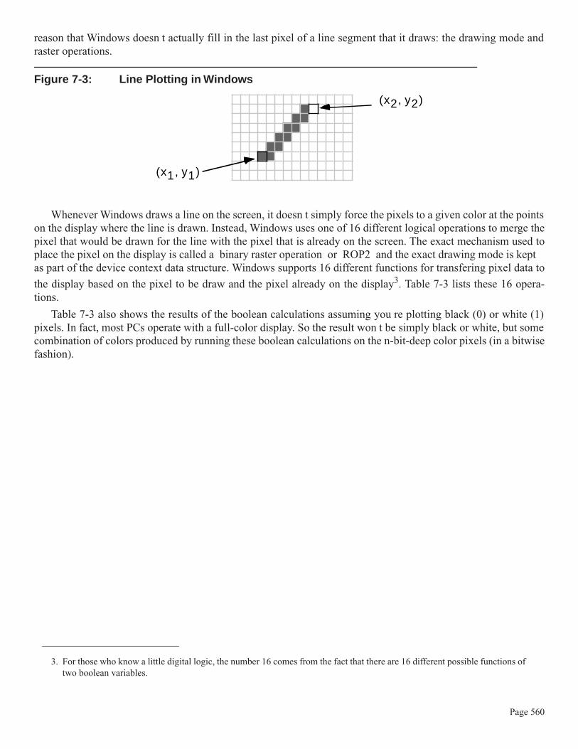
reason that Windows doesn t actually fill in the last pixel of a line segment that it draws: the drawing mode andraster operations.
Figure 7-3: Line Plotting in Windows
Whenever Windows draws a line on the screen, it doesn t simply force the pixels to a given color at the pointson the display where the line is drawn. Instead, Windows uses one of 16 different logical operations to merge thepixel that would be drawn for the line with the pixel that is already on the screen. The exact mechanism used toplace the pixel on the display is called a binary raster operation or ROP2 and the exact drawing mode is keptas part of the device context data structure. Windows supports 16 different functions for transfering pixel data to
the display based on the pixel to be draw and the pixel already on the display3. Table 7-3 lists these 16 opera-tions.
Table 7-3 also shows the results of the boolean calculations assuming you re plotting black (0) or white (1)pixels. In fact, most PCs operate with a full-color display. So the result won t be simply black or white, but somecombination of colors produced by running these boolean calculations on the n-bit-deep color pixels (in a bitwisefashion).
3. For those who know a little digital logic, the number 16 comes from the fact that there are 16 different possible functions of two boolean variables.
(x1, y1)
(x2, y2)
Page 560

Table 7-3: Windows Pen Drawing Modes
Table 7-3 shows the results of the boolean calculations assuming you re plotting black (0) or white (1) pixels.In fact, most PCs operate with a full-color display. So the result won t be simply black or white, but some combi-nation of colors produced by running these boolean calculations on the n-bit-deep color pixels (in a bitwise fash-ion).
The CopyModes.hla application demonstrates the various Window pen copying modes when using black andwhite on the display (sorry, but reproduction as well as logistical problems prevent the presentation of a versionthat uses color; however, feel free to modify CopyModes.hla appropriately to see what happens when you usedifferent colors beyond black and white). This program begins by drawing a set of 16 wide black lines on the dis-play, then it draws two lines (one black, one white) over the top of each of these 16 background lines, using a dif-ferent copy mode in each of the 16 cases (Figure 7-4 shows the output this program produces).
Pen 1 1 0 0 Mathematical Description
Drawing ModeDisplay 1 0 1 0
0 0 0 0 0 R2_BLACK
0 0 0 1 not (pen or display) R2_NOTMERGEPEN
0 0 1 0 (not pen )& display R2_MASKNOTPEN
0 0 1 1 not pen R2_NOTCOPYPEN
0 1 0 0 pen and (not display) R2_MASKPENNOT
0 1 0 1 not display R2_NOT
0 1 1 0 pen xor display R2_XORPEN
0 1 1 1 not(pen and display) R2_NOTMASKPEN
1 0 0 0 pen and display R2_MASKPEN
1 0 0 1 not (pen xor display) R2_NOTXORPEN
1 0 1 0 display R2_NOP
1 0 1 1 (not pen) or display R2_MERGENOTPEN
1 1 0 0 pen R2_COPYPEN (default)
1 1 0 1 pen or (not display) R2_MERGEPENNOT
1 1 1 0 pen or display R2_MERGEPEN
1 1 1 1 1 R2_WHITE
Page 561

Figure 7-4: CopyModes.hla Program Output
Note that the CopyModes.hla program uses the WinMain library developed earlier to reduce the size of ourWin32 assembly programs.
// CopyModes.hla-//// Program that demonstrates the use of the SetROP2 API function to set// the Windows copy mode (for drawing with a pen).//// Note: this is a unit because it uses the WinMail library module that// provides a win32 main program for us.
unit CopyModes;
#includeonce( "rand.hhf" )#includeonce( "hll.hhf" )
Page 562

#includeonce( "memory.hhf" )#includeonce( "math.hhf" )#includeonce( "w.hhf" )#includeonce( "wpa.hhf" )#includeonce( "winmain.hhf" )
?@NoDisplay := true;?@NoStackAlign := true;
// copy_t-// This record type holds a caption string and a copy mode// value for use when demostrating the 16 different copy// modes on the display.
type copy_t: record msg :string; cm :dword; endrecord;
// cmm-// This is a utility macro used to save some typing when// filling in an array of 16 "copy_t" array elements. An// invocation of the form "cmm( xyz )" produces the following://// copy_t:[ "xyz", w.xyz ]//// The intent is to supply a Windows Drawing mode as the macro// argument (see the copyData array, below).
#macro cmm( mode ); copy_t:[ @string( mode ), @text( "w." + @string( mode )) ]#endmacro
static bkgndPen :dword; whitePen :dword; fgndPen :dword;
copyData :copy_t[16] := [ cmm( R2_BLACK ), cmm( R2_NOTMERGEPEN ), cmm( R2_MASKNOTPEN ), cmm( R2_NOTCOPYPEN ), cmm( R2_MASKPENNOT ), cmm( R2_NOT ), cmm( R2_XORPEN ), cmm( R2_NOTMASKPEN ), cmm( R2_MASKPEN ), cmm( R2_NOTXORPEN ), cmm( R2_NOP ), cmm( R2_MERGENOTPEN ),
Page 563

cmm( R2_COPYPEN ), cmm( R2_MERGEPENNOT ), cmm( R2_MERGEPEN ), cmm( R2_WHITE ) ];
readonly
ClassName :string := "CopyModesWinClass"; // Window Class Name AppCaption :string := "CopyModes Program"; // Caption for Window
// The dispatch table: // // This table is where you add new messages and message handlers // to the program. Each entry in the table must be a MsgProcPtr_t // record containing two entries: the message value (a constant, // typically one of the w.WM_***** constants found in windows.hhf) // and a pointer to a "MsgProcPtr_t" procedure that will handle the // message. Dispatch :MsgProcPtr_t; @nostorage;
MsgProcPtr_t MsgProcPtr_t:[ w.WM_DESTROY, &QuitApplication ], MsgProcPtr_t:[ w.WM_PAINT, &Paint ], MsgProcPtr_t:[ w.WM_CREATE, &Create ], // Insert new message handler records here. MsgProcPtr_t:[ 0, NULL ]; // This marks the end of the list.
/**************************************************************************//* W I N M A I N S U P P O R T C O D E *//**************************************************************************/
// initWC - We don't have any initialization to do, so just return:
procedure initWC; @noframe;begin initWC;
ret();
end initWC;
// appCreateWindow- the default window creation code is fine, so just// call defaultCreateWindow.
procedure appCreateWindow; @noframe;begin appCreateWindow;
jmp defaultCreateWindow;
Page 564

end appCreateWindow;
// appException-//// Gives the application the opportunity to clean up before// aborting when an unhandled exception comes along:
procedure appException( theException:dword in eax );begin appException;
push( eax ); // Save exception so we can re-raise it.
// Delete the pens we created in the Create procedure:
w.DeleteObject( bkgndPen ); w.DeleteObject( whitePen ); w.DeleteObject( fgndPen );
pop( eax ); raise( eax );
end appException;
// This is the custom message translation procedure.// We're not doing any custom translation, so just return EAX=0// to tell the caller to go ahead and call the default translation// code.
procedure LocalProcessMsg( var lpmsg:w.MSG ); begin LocalProcessMsg;
xor( eax, eax );
end LocalProcessMsg; /**************************************************************************//* A P P L I C A T I O N S P E C I F I C C O D E *//**************************************************************************/
// The Create procedure creates all the pens we're going to use// in this application.
procedure Create( hwnd: dword; wParam:dword; lParam:dword );begin Create;
// Create a thick, black, pen for drawing the axis:
w.CreatePen( w.PS_SOLID, 24, RGB( $0, $0, $0) ); mov( eax, bkgndPen );
// Create a thin, black, pen for demonstrating the copy modes:
Page 565

w.CreatePen( w.PS_SOLID, 12, RGB( $0, $0, $0) ); mov( eax, fgndPen );
// Create a thin, white, pen for demonstrating the copy modes:
w.CreatePen( w.PS_SOLID, 12, RGB( $FF, $FF, $FF) ); mov( eax, whitePen );
end Create;
// QuitApplication://// This procedure handles the w.WM_DESTROY message.// It tells the application to terminate. This code sends// the appropriate message to the main program's message loop// that will cause the application to terminate. procedure QuitApplication( hwnd: dword; wParam:dword; lParam:dword );begin QuitApplication;
// Delete the pens we created in the Create procedure:
w.DeleteObject( bkgndPen ); w.DeleteObject( whitePen ); w.DeleteObject( fgndPen );
w.PostQuitMessage( 0 );
end QuitApplication;
// Paint://// This procedure handles the w.WM_PAINT message.
procedure Paint( hwnd: dword; wParam:dword; lParam:dword );var hdc :dword; // Handle to video display device context ps :w.PAINTSTRUCT; // Used while painting text. oldPen :dword;
begin Paint;
// Message handlers must preserve EBX, ESI, and EDI. // (They've also got to preserve EBP, but HLA's procedure // entry code already does that.) push( ebx ); push( esi ); push( edi ); // Note that all GDI calls must appear within a
Page 566

// BeginPaint..EndPaint pair. BeginPaint( hwnd, ps, hdc );
// Draw a set of black lines in the window:
SelectObject( bkgndPen ); // Select the fat black pen. mov( eax, oldPen ); // Save, so we can restore later
// Demonstrate each of the 16 pen/copy/draw modes, // one mode per iteration of the following loop:
for( mov( 0, esi ); esi < 16; inc( esi )) do
// Compute the Y-offset for each line // on the display:
intmul( 32, esi, edi ); add( 8, edi );
// Print a caption for each line:
TextOut ( 32, edi, copyData.msg[ esi*8 ], str.length( copyData.msg[ esi*8] ) ); add( 8, edi ); // Display a background black line // to draw against:
SetROP2( w.R2_COPYPEN ); SelectObject( bkgndPen ); // Select the fat black pen. MoveToEx( 240, edi, NULL ); LineTo( 440, edi );
// Change the current copy mode to demonstrate each // of the copy modes:
SetROP2( copyData.cm[ esi*8 ] );
// Draw a white line, using the curren copy mode, // over the first half of the background line:
SelectObject( whitePen ); // Select the fat black pen. MoveToEx( 200, edi, NULL ); LineTo( 330, edi );
// Draw a black line, using the current copy mode, // over the second half of the background line.
SelectObject( fgndPen ); // Select the fat black pen. MoveToEx( 350, edi, NULL ); LineTo( 480, edi );
Page 567

endfor;
// Restore original pen:
SelectObject( oldPen ); SetROP2( w.R2_COPYPEN );
EndPaint;
pop( edi ); pop( esi ); pop( ebx );
end Paint; end CopyModes;
7.6.7: Paths
Lines are useful graphic primitives from which you can draw many other types of objects. For example, withfour lines you can create a rectangle on the display. As you ll see in a moment, however, Windows treats con-nected objects like rectangles a little differently than it does an arbitrary set of four lines drawn on the screen. Forexample, you can fill rectangular objects with some pattern or color whereas no such concept like fill exists fora set of four arbitrary lines appearing on the display; even if the position of those four lines just happen to visu-ally form a rectangle on the display. What is needed is some mechanism for telling Windows that a collection oflines form a special object. That special mechanism is the path.
A path in Windows is a recording. That is, you record a sequence of line drawing operations within Windowsand then play that recording back to draw those sequence of lines as a single object (this is known as renderingthe path). To record a path, you use the w.BeginPath and w.EndPath API functions:
static BeginPath: procedure( hdc:dword ); @stdcall; @returns( "eax" ); @external( "__imp__BeginPath@4" );
EndPath: procedure( hdc :dword ); @stdcall; @returns( "eax" ); @external( "__imp__EndPath@4" );
Calling w.BeginPath (passing the device context handle that BeginPaint produces) tells Windows to startrecording all calls that draw lines (e.g., LineTo, PolylineTo, BezierTo, and so on) into an internal buffer ratherthan rendering them to the output device. When you call w.EndPath (also passing the device context handle),Windows finishes the recording. You may then draw the path you ve recorded as a single object using thew.StrokePath API call:
Page 568

static StrokePath: procedure( hdc:dword ); @stdcall; @returns( "eax" ); @external( "__imp__StrokePath@4" );
Here is a typical example of such a w.BeginPath/w.Endpath/w.StrokePath calling sequence:
w.BeginPath( hdc );
// Draw the path that forms a triangle:
MoveToEx( edi, 270, NULL ); add( 40, edi ); LineTo( edi, 270 ); LineTo( edi, 230 ); sub( 40, edi ); LineTo( edi, 270 );
w.EndPath( hdc ); w.StrokePath( hdc );
As these are all GDI calls, they must appear inside a BeginPath/EndPaint or comparable sequence.
Now it may seem like a lot of work to go through the process of creating a path. After all, you can just as eas-ily draw these lines on the display using the line drawing APIs without recording and rendering the path. How-ever, you should note that Windows will draw paths a little differently than it draws arbitrary lines (you ll see thedifference in a moment). Another advantage of using paths is that you can tell Windows to fill the enclosedregions of a path with some pattern (we ll take a look at this capability a little later in this chapter). Rest assured,there are some very good reasons for recording a sequence of lines as a path rather than drawing them directly.
One advantage of creating a path is that you can create a closed object when drawing a path, something thatmay not be so easy to do when drawing the objects outside a path. You can close a path you re recording with acall to the w.CloseFigure API call:
static CloseFigure: procedure( hdc:dword ); @stdcall; @returns( "eax" ); @external( "__imp__CloseFigure@4" );
The w.CloseFigure API function draws a straight line from the endpoint of the last line you ve drawn, to thebeginning of the first line you ve drawn in the path. Note that simply drawing a line to the same coordinate as thestarting point of your line does not create a closed figure. Remember, LineTo and other line drawing functionsdraw up to, but not including, the end point you specify. From Window s perspective, this is not necessarily aclosed object. Therefore, calling the w.CloseFigure function is a good way to finish drawing a path before clos-ing the path with a call to w.EndPath.
Technically, a path inside a w.BeginPath..w.EndPath sequence consists of all the connected lines thatyou ve drawn (that is, the sequence of LineTo, Polylineto, BezierTo, and so on, calls you ve made). If youcall MoveToEx within a path sequence, Windows treats the following calls as a separate path (a subpath ) andrenders those objects separately. Usually, you d create a single, connected, object inside a w.Begin-
Path..w.EndPath sequence.
Page 569

7.6.8: Extended Pen Styles
When you draw lines that are one pixel in width, connecting lines together (e.g., as part of a path) is relativelystraight-forward - just draw the first pixel of the second line in some sequence just beyond the last pixel of thefirst line in some sequence (and so on for each additional line) and, presto, the two lines mate and look like a sin-gle contiguous object. However, when you create a pen whose width is greater than one pixel, attempts to drawtwo connected lines via a sequence of LineTo (or similar) calls produces some annoying artifacts on the display.to alleviate these problems, Windows provides a second pen creation routine, w.ExtCreatePen, that lets youspecify some additional pen styles specifically for wide pens. The prototype for w.ExtCreatePen is
static ExtCreatePen: procedure ( dwPenStyle :dword; dwWidth :dword; var lplb :w.LOGBRUSH; dwStyleCount :dword; var lpStyle :dword ); @stdcall; @returns( "eax" ); @external( "__imp__ExtCreatePen@20" );
The dwPenStyle parameter is where you specify the new styles (we ll get to these in a moment), the dwWidthparameter specifies the width (in pixels or logical units) of the line, the lplb parameter is where you specify apattern and color for the pen to draw. The dwStyleCount and lpStyle parameters we ll just set to zero (NULL)for the time being.
The dwPenStyle parameter can have all the bit values allowed for the styles that are legal for the w.Create-Pen API call. In addition to those styles, you may also specify the styles shown in Table 7-4. As with the stylevalues you specify for w.CreatePen, these are all single bit values and you may combine these values using theHLA compile-time bitwise-OR operator ( | ).
Table 7-4: dwPenStyle Values for the w.ExtCreatePen API Function
Pen Style Description
w.PS_COSMETIC Generally used with dashed or dotted pens (though this was a restric-tion of Windows 95 that has long since been removed).
w.PS_GEOMETRIC This tells Windows to draw the line using a width specified in logical units).
w.PS_ENDCAP_ROUND This style tells Windows to “cap” each end of the line with a half-cir-cle. Note that the cap extends beyond the endpoints of the line. See Fig-ure 7-5 for an example.
w.PS_ENDCAP_SQUARE This style tells Windows to “cap” each end of the line with a rectangle whose width is half the line’s width. This rectangular cap extends beyond the endpoints of the line. See Figure 7-5 for an example.
Page 570

Figure 7-5: Endcaps on a Line Drawn by Windows
w.PS_ENDCAP_FLAT This style tells Windows to skip capping each end of the line. The line is drawn as a rectangle between the two endpoints the caller passes to the line drawing routine. See Figure 7-5 for an example.
w.PS_JOIN_ROUND This style defines how Windows will connect two lines that are drawn in sequence (that is, the endpoint of one line is the starting point of the second line). This particular style specifies a rounded edge between thetwo lines when drawing lines in a sequence. See Figure 7-6 for an example.
w.PS_JOIN_BEVEL This style defines how Windows will connect two lines that are drawn in sequence (that is, the endpoint of one line is the starting point of the second line). This particular style specifies a straight edge between the edges of the two lines when drawing lines in a sequence. See Figure 7-6 for an example.
w.PS_JOIN_MITER This style defines how Windows will connect two lines that are drawn in sequence (that is, the endpoint of one line is the starting point of the second line). This particular style tells Windows to extend the outside edges of two lines until those edges intersect. See Figure 7-6 for an example.
Pen Style Description
Single pixel line drawnbetween two endpoints
Wide line drawn usingFLAT endcaps
Wide line drawn usingROUND endcaps
Wide line drawn usingSQUARE endcaps
Page 571

Figure 7-6: Line Joins Drawn by Windows
Note that the w.PS_ENDCAP_* styles are mutually exclusive (that is, you may only select one of the endcapstyles). Likewise, the w.PS_JOIN_* styles are all mutually exclusive and you may only select one of them.
Windows draws lines using the w.PS_JOIN_* styles only when it is rendering a path. If you set these stylesfor a given pen and then draw a sequence of lines without first creating a path, Windows will not bother to jointhe lines as you would expect.
The lplb parameter you pass to w.ExtCreatePen specifies a brush that Windows will use when drawing theline. We ll talk about brushes a little later in this chapter. For now, just realize that this parameter is where youspecify the color of the line that you will draw with the pen. The lplb parameter is of type w.LOGBRUSH (a Win-dows brush type) and this is a record object that has three fields we ll need to initialize before calling w.Ext-
CreatePen: the lbStyle field, the lbColor field, and the lbHatch field. For normal pens, you ll set the lbStylefield to w.BS_SOLID (brush style solid), the lbColor field to whatever RGB value you want to draw the linewith, and the lbHatch field we ll set to zero (no hatch markings). We ll take another look at brush style valueswhen we talk about brushes later in this chapter.
Two lines joined at thesame endpoint using thePS_JOIN_BEVEL style
Two lines joined at thesame endpoint using thePS_JOIN_ROUND style
Two lines joined at thesame endpoint without aJOIN style
Two lines joined at thesame endpoint using thePS_JOIN_MITER style
Page 572

The ExtendedPens.hla application demonstrates the use of the w.ExtCreatePen API function. It draws asequence of lines with various endcaps and then draws a series of triangles to demonstrate the path operationsand the pen join modes. Figure 7-7 shows the output from this application.
Figure 7-7: ExtendedPens.hla Program Output
As usual, now, the ExtendedPen.hla application uses the WinMain.lib library files to reduce the size of the sourcefile.
// ExtendedPens.hla-//// Program that demonstrates the use of the ExtCreatePen API function.//// Note: this is a unit because it uses the WinMail library module that// provides a win32 main program for us.
unit ExtendedPens;
#includeonce( "rand.hhf" )#includeonce( "hll.hhf" )#includeonce( "memory.hhf" )#includeonce( "math.hhf" )#includeonce( "w.hhf" )#includeonce( "wpa.hhf" )#includeonce( "winmain.hhf" )
?@NoDisplay := true;?@NoStackAlign := true; readonly
ClassName :string := "ExtendedPensWinClass"; // Window Class Name AppCaption :string := "ExtendedPens Program"; // Caption for Window
Page 573
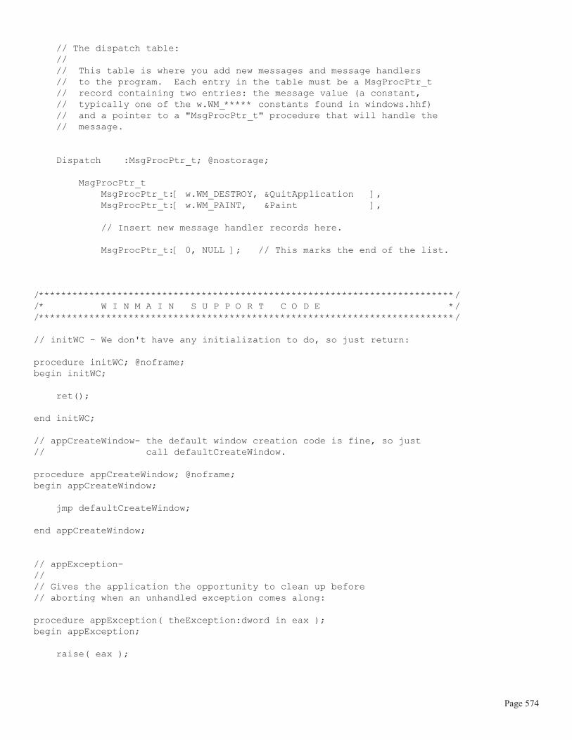
// The dispatch table: // // This table is where you add new messages and message handlers // to the program. Each entry in the table must be a MsgProcPtr_t // record containing two entries: the message value (a constant, // typically one of the w.WM_***** constants found in windows.hhf) // and a pointer to a "MsgProcPtr_t" procedure that will handle the // message. Dispatch :MsgProcPtr_t; @nostorage;
MsgProcPtr_t MsgProcPtr_t:[ w.WM_DESTROY, &QuitApplication ], MsgProcPtr_t:[ w.WM_PAINT, &Paint ], // Insert new message handler records here. MsgProcPtr_t:[ 0, NULL ]; // This marks the end of the list.
/**************************************************************************//* W I N M A I N S U P P O R T C O D E *//**************************************************************************/
// initWC - We don't have any initialization to do, so just return:
procedure initWC; @noframe;begin initWC;
ret();
end initWC;
// appCreateWindow- the default window creation code is fine, so just// call defaultCreateWindow.
procedure appCreateWindow; @noframe;begin appCreateWindow;
jmp defaultCreateWindow;
end appCreateWindow;
// appException-//// Gives the application the opportunity to clean up before// aborting when an unhandled exception comes along:
procedure appException( theException:dword in eax );begin appException;
raise( eax );
Page 574

end appException;
// This is the custom message translation procedure.// We're not doing any custom translation, so just return EAX=0// to tell the caller to go ahead and call the default translation// code.
procedure LocalProcessMsg( var lpmsg:w.MSG ); begin LocalProcessMsg;
xor( eax, eax );
end LocalProcessMsg; /**************************************************************************//* A P P L I C A T I O N S P E C I F I C C O D E *//**************************************************************************/
// QuitApplication://// This procedure handles the w.WM_DESTROY message.// It tells the application to terminate. This code sends// the appropriate message to the main program's message loop// that will cause the application to terminate. procedure QuitApplication( hwnd: dword; wParam:dword; lParam:dword );begin QuitApplication;
w.PostQuitMessage( 0 );
end QuitApplication;
// Paint://// This procedure handles the w.WM_PAINT message.
procedure Paint( hwnd: dword; wParam:dword; lParam:dword );var hdc :dword; // Handle to video display device context. oldPen :dword; // Used to save the original pen. grayPen :dword; roundPen :dword; squarePen :dword; flatPen :dword; tempPen :dword; ps :w.PAINTSTRUCT; // Used while painting text. lb :w.LOGBRUSH; // Used to create pens.
readonly
Page 575

penStyles: dword[ 9 ] := [ w.PS_SOLID | w.PS_GEOMETRIC | w.PS_ENDCAP_ROUND | w.PS_JOIN_ROUND, w.PS_SOLID | w.PS_GEOMETRIC | w.PS_ENDCAP_ROUND | w.PS_JOIN_BEVEL, w.PS_SOLID | w.PS_GEOMETRIC | w.PS_ENDCAP_ROUND | w.PS_JOIN_MITER, w.PS_SOLID | w.PS_GEOMETRIC | w.PS_ENDCAP_SQUARE | w.PS_JOIN_ROUND, w.PS_SOLID | w.PS_GEOMETRIC | w.PS_ENDCAP_SQUARE | w.PS_JOIN_BEVEL, w.PS_SOLID | w.PS_GEOMETRIC | w.PS_ENDCAP_SQUARE | w.PS_JOIN_MITER, w.PS_SOLID | w.PS_GEOMETRIC | w.PS_ENDCAP_FLAT | w.PS_JOIN_ROUND, w.PS_SOLID | w.PS_GEOMETRIC | w.PS_ENDCAP_FLAT | w.PS_JOIN_BEVEL, w.PS_SOLID | w.PS_GEOMETRIC | w.PS_ENDCAP_FLAT | w.PS_JOIN_MITER ];
begin Paint;
// Message handlers must preserve EBX, ESI, and EDI. // (They've also got to preserve EBP, but HLA's procedure // entry code already does that.) push( ebx ); push( esi ); push( edi ); // Create a thin, gray, pen for annotation purposes:
w.CreatePen( w.PS_SOLID, 0, RGB( $A0, $A0, $A0) ); mov( eax, grayPen );
// Set up "lb" for use when creating the following pens:
mov( w.BS_SOLID, lb.lbStyle ); mov( RGB( 0, 0, 0 ), lb.lbColor ); mov( 0, lb.lbHatch );
// Create a thick, black, pen for drawing the axis:
w.ExtCreatePen ( w.PS_SOLID | w.PS_GEOMETRIC | w.PS_ENDCAP_ROUND, 16, lb, 0, NULL ); mov( eax, roundPen );
w.ExtCreatePen ( w.PS_SOLID | w.PS_GEOMETRIC | w.PS_ENDCAP_SQUARE, 16, lb, 0, NULL ); mov( eax, squarePen );
Page 576
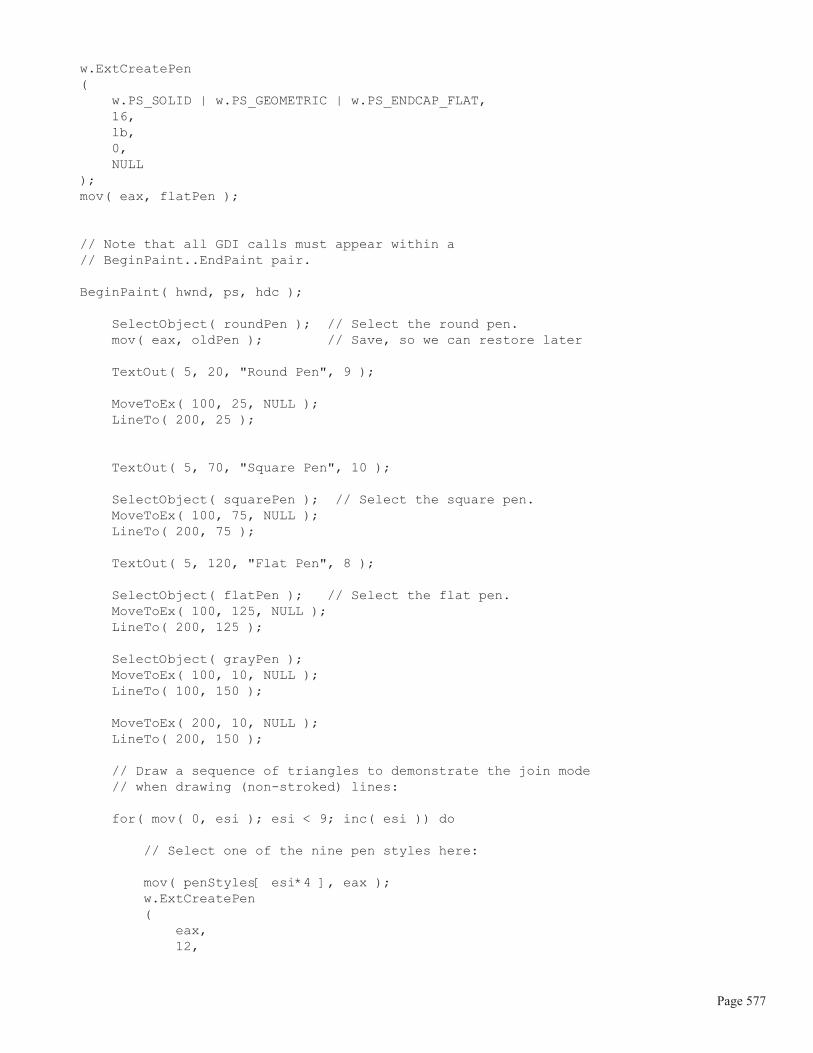
w.ExtCreatePen ( w.PS_SOLID | w.PS_GEOMETRIC | w.PS_ENDCAP_FLAT, 16, lb, 0, NULL ); mov( eax, flatPen );
// Note that all GDI calls must appear within a // BeginPaint..EndPaint pair. BeginPaint( hwnd, ps, hdc );
SelectObject( roundPen ); // Select the round pen. mov( eax, oldPen ); // Save, so we can restore later
TextOut( 5, 20, "Round Pen", 9 );
MoveToEx( 100, 25, NULL ); LineTo( 200, 25 );
TextOut( 5, 70, "Square Pen", 10 );
SelectObject( squarePen ); // Select the square pen. MoveToEx( 100, 75, NULL ); LineTo( 200, 75 );
TextOut( 5, 120, "Flat Pen", 8 );
SelectObject( flatPen ); // Select the flat pen. MoveToEx( 100, 125, NULL ); LineTo( 200, 125 );
SelectObject( grayPen ); MoveToEx( 100, 10, NULL ); LineTo( 100, 150 );
MoveToEx( 200, 10, NULL ); LineTo( 200, 150 );
// Draw a sequence of triangles to demonstrate the join mode // when drawing (non-stroked) lines:
for( mov( 0, esi ); esi < 9; inc( esi )) do
// Select one of the nine pen styles here:
mov( penStyles[ esi*4 ], eax ); w.ExtCreatePen ( eax, 12,
Page 577

lb, 0, NULL ); mov( eax, tempPen ); SelectObject( eax );
// Draw a triangle using the selected pen:
intmul( 64, esi, edi ); add( 20, edi ); MoveToEx( edi, 200, NULL ); add( 40, edi ); LineTo( edi, 200 ); LineTo( edi, 160 ); sub( 40, edi ); LineTo( edi, 200 );
// Draw a triangle using the thin, gray, pen // over the top of the existing triangle to // show where we've drawn:
SelectObject( grayPen ); add( 40, edi ); LineTo( edi, 200 ); LineTo( edi, 160 ); sub( 40, edi ); LineTo( edi, 200 );
// Delete the pen we created above:
w.DeleteObject( tempPen ); endfor;
// Draw a sequence of triangles to demonstrate // the join mode when drawing stroked lines:
for( mov( 0, esi ); esi < 9; inc( esi )) do
// Select one of the nine pen styles here:
mov( penStyles[ esi*4 ], eax ); w.ExtCreatePen ( eax, 12, lb, 0, NULL ); mov( eax, tempPen ); SelectObject( eax );
// Capture all the strokes:
Page 578

w.BeginPath( hdc );
// Draw a triangle using the selected pen: // // Draw the triangles 64 units apart:
intmul( 64, esi, edi ); // Start at x-coordinate 20 for the first triangle:
add( 20, edi ); // Draw the path that forms the triangle:
MoveToEx( edi, 270, NULL ); add( 40, edi ); LineTo( edi, 270 ); LineTo( edi, 230 ); sub( 40, edi ); LineTo( edi, 270 );
// Create a closed path // (so 'end' joins with 'start' properly):
w.CloseFigure( hdc );
w.EndPath( hdc );
// Actually draw the triangle based on the path // we've captured above:
w.StrokePath( hdc );
// Draw a triangle using the thin, gray, pen // over the top of the existing triangle to // show where we've drawn:
SelectObject( grayPen ); intmul( 64, esi, edi ); add( 20, edi ); MoveToEx( edi, 270, NULL ); add( 40, edi ); LineTo( edi, 270 ); LineTo( edi, 230 ); sub( 40, edi ); LineTo( edi, 270 );
// Delete the pen we created above:
w.DeleteObject( tempPen ); endfor;
// Restore original pen:
SelectObject( oldPen );
Page 579

EndPaint;
// Delete the pens we created:
w.DeleteObject( grayPen ); w.DeleteObject( roundPen ); w.DeleteObject( squarePen ); w.DeleteObject( flatPen ); pop( edi ); pop( esi ); pop( ebx );
end Paint; end ExtendedPens;
7.7: Bounding Boxes and Rectangles in Windows
Once you get past lines, that have a very simple mathematical definition (two points!), the way people defineother objects varies tremendously. Windows, like the Macintosh before it, uses the concept of a bounding boxto descibe how to draw complex objects. A bounding box is the smallest rectangular box (realized with horizon-tal and vertical lines) that completely surrounds an object. In Windows, you ll usually specify a bounding boxusing a w.RECT object. Under Windows, a w.RECT object takes the following form:type RECT: record left: dword; top: dword; right: dword; bottom: dword; endrecord;
The left field specifies the x-coordinate of the left-hand side of the bounding rectangle (in local coordinateunits). The top field specifies the y-coordinate of the top of the bounding rectangle. The right field specifies thex-coordinate of the right-hand side of the bounding box. The bottom field specifies the y-coordinate of the bot-tom of the bounding rectangle (see Figure 7-8). Some people also like to define a bounding box by two points at
Page 580

opposite corners of the rectangle. Usually they use the two points specified by (left, top) and (right, bottom), seeFigure 7-8, but (right, top) and (left, bottom) could just as easily describe the rectangle.
Figure 7-8: Bounding Rectangle Relationship with a w.RECT Object
One problem with the bounding box model is that a bounding box rectangle and a rectangle you actually ren-der on the screen are similar in a visual sense. However, there is a big difference between the two. A boundingbox is a mathematical rectangle made up of mathematical lines. In mathematics, a line has no width. This is alsotrue for a bounding box, as a bounding box is a mathematical concept made up of mathematical lines. A rectanglewe render on the display, however, is not a mathematical rectangle because the lines we use to draw it must havesome width (i.e., at least one pixel) in order to be visible on the display. So the question that should come up isHow does one reconcile the differences between these two types of rectangles when physically drawing objects(that use a bounding box) in a device context? The answer is that Windows always draws from the top coordi-nate to, but not including, the bottom coordinate and from the left coordinate to, but not including, the right coor-dinate. The reasons for doing it this way are the same reasons Windows draws a line from the line s starting pointup to, but not including, the end point (see Figure 7-9).
left right
top
bottom
(left, top)
(right, bottom)
Page 581

Figure 7-9: How the Bounding Box Circumscribes an Object
The Windows API provides several different functions you can call to manipulate rectangles. A typical exam-ple is the w.SetRect function:
static SetRect: procedure ( var lprc :RECT; xLeft :dword; yTop :dword; xRight :dword; yBottom :dword ); @stdcall; @returns( "eax" ); @external( "__imp__SetRect@20" );
The w.SetRect function initializes the w.RECT object you pass as its first parameter with the coordinate valuesyou pass in the remaining four parameters. While this function does offer a fair amount of convenience, I wouldhope you realize that you re paying a heavy price whenever you call this API function to initialize a w.RECTstructure. If you want the convenience of this function, you should create your own macro that does the same job,e.g.:
#macro SetRect( theRect, left, top, right, bottom );mov( left, (type w.RECT theRect).left );mov( top, (type w.RECT theRect).top );
top
bottom
left right
Object that the bounding rectanglecircumscribes fits within this area
Page 582

mov( bottom, (type w.RECT theRect).bottom );mov( right, (type w.RECT theRect).right );
#endmacro...
SetRect( SomeRectangle, 0, 0, 5, 10 );
This macro coerced its first parameter to type w.RECT to allow you to pass parameters like the following:
SetRect( [ebx], 0, 1, 2, 3 );
Of course, it s perfectly legal to pass an actual w.RECT object as the first parameter, as well.
Windows provides several additional rectangle related functions that may prove useful when dealing withobjects of type w.RECT (e.g., bounding boxes). Though these routines are usable anyplace you need to manipu-late w.RECT objects in Windows, this seems like a good place to introduce these functions as many of them arequite useful when working with bounding boxes.
RectVisible: procedure( hdc:dword; var lprc:RECT ); @stdcall; @returns( "eax" ); @external( "__imp__RectVisible@8" );
The w.RectVisible function checks to see if the rectangle specified by lprc is within the clipping region of thedevice context whose handle is the first parameter to this call. This function returns false (zero) if no part of therectangle is within the clipping region. This function returns a non-zero value indicating true if some part of therectangle is within the device context s clipping region.
CopyRect: procedure ( var lprcDst :RECT; var lprcSrc :RECT ); @stdcall; @returns( "eax" ); @external( "__imp__CopyRect@8" );
The w.CopyRect function will make a copy of the source rectangle into the destination rectangle. Note that copy-ing a rectangle (which is just four dwords) is a fairly trivial operation and writing a macro to do this operationwould be a far more efficient solution, e.g.,
#macro CopyRect( src, dest ); // Note the reversal of the parametersmov( (type w.RECT src).top, eax );mov( eax, (type w.RECT dest).top );mov( (type w.RECT src).left, eax );mov( eax, (type w.RECT dest).left );mov( (type w.RECT src).bottom, eax );mov( eax, (type w.RECT dest).bottom );mov( (type w.RECT src).right, eax );mov( eax, (type w.RECT dest).right );
#endmacro
Page 583

Note that this macro will wipe out the value previously held in the EAX register (of course, the w.CopyRect APIfunction also changes the value in EAX).
EqualRect: procedure( var lprc1:RECT; var lprc2:RECT ); @stdcall; @returns( "eax" ); @external( "__imp__EqualRect@8" );
The w.EqualRect function compares the coordinates of two rectangles and returns true (non-zero) in EAX if thetwo rectangles have the same coordinates; it returns false (zero) if the coordinates are not the same. As for manyof the simler rectangle routines, you ll get better performance if you compare the coordinate directly, yourself (orwrite a macro to do this).
InflateRect: procedure ( var lprc :RECT; _dx :dword; _dy :dword ); @stdcall; @returns( "eax" ); @external( "__imp__InflateRect@12" );
The w.InflateRect function increases the width of the rectangle specified by the signed integer value found in_dx. It also increases the height of the rectangle by the value found in _dy. The _dx and _dy values may be nega-tive, which will shrink the size by the specified amount.
IntersectRect: procedure ( var lprcDst :RECT; var lprcSrc1 :RECT; var lprcSrc2 :RECT ); @stdcall; @returns( "eax" ); @external( "__imp__IntersectRect@12" );
The w.IntersectRect API function computes the intersection of two rectangles and stores the resulting rectan-gle into the rectangle object you pass for the lprcDst parameter. If the intersection of the two source rectanglesis empty, then this function returns an empty rectangle (which is a w.RECT value with all coordinates set to zero).
OffsetRect: procedure ( var lprc :RECT; _dx :dword; _dy :dword ); @stdcall; @returns( "eax" ); @external( "__imp__OffsetRect@12" );
Page 584

The w.OffsetRect function adds the signed integer value found in _dx to the left and right fields of the lprcw.RECT object you pass as a parameter. It also adds the value in _dy to the top and bottom fields. The _dx and_dy values may be negative, which will shrink the coordinates by the specified amount. Note that if _dx and _dyare both constant values, you can do this same task with only four add instructions:
add( _dx, lprc.left ); // _dx must be a constant!add( _dx, lprc.right );add( _dy, lprc.top ); // _dy must be a constant!add( _dy, lprc.bottom );
SetRectEmpty: procedure( var lprc:RECT ); @stdcall; @returns( "eax" ); @external( "__imp__SetRectEmpty@4" );
The w.SetRectEmpty function sets all the coordinates of the specified rectangle to zero (the empty rectangle). Of course, four simple mov instructions will also do the same trick. Recommendation: make a macro for this operation if you do it frequently.
SubtractRect: procedure ( var lprcDst :RECT; var lprcSrc1 :RECT; var lprcSrc2 :RECT ); @stdcall; @returns( "eax" ); @external( "__imp__SubtractRect@12" );
The w.SubtractRect function creates a new rectangle by subtracting the coordinates in lprcSrc2 from the cor-responding coordinates in lprcSrc1. This function stores the resulting rectangle in the object pointed at bylprcDst.
UnionRect: procedure ( var lprcDst :RECT; var lprcSrc1 :RECT; var lprcSrc2 :RECT ); @stdcall; @returns( "eax" ); @external( "__imp__UnionRect@12" );
The w.UnionRect API function takes the union of two rectangles and returns that value as the destination rectan-gle. The union of two rectangles is the smallest rectangle that complete surrounds the two source rectangles. Thisis the minimum of the two left and top values, and the maximum of thetwo right and bottom values in the sourcerectangles.
Page 585

7.8: Drawing Objects in Windows
Although you can use Windows line drawing primitives to draw just about any shape you please, there are acouple of problems with this approach:
¥ You actually have to know the mathematical details behind the creation of such objects (and they aren tall as trivial as drawing rectangles).
¥ Some objects cannot be drawn efficiently using only line drawing primitives (e.g., filled objects).
¥ You ll have to write and test a lot of code.
Fortunately, you don t have to drop down to this level of detail. Windows provides lot of additional graphicsprimitives you can use to draw shapes in a device context. Even for those application specific objects that Win-dows does not provide for you, you re better off creating those objects using the full set of graphic primitives inWindows rather than attempting to draw everything using lines.
7.8.1: Filling Objects and Windows’ Brushes
One big differece between simple line objects and the more complex objects that Windows can render is thefact that many graphical objects can enclose a region. For example, consider a rectangle that consists of fourlines; those four lines enclose a rectangular region. When drawing in black and white, a typical rectangle mightconsist of four black lines enclosing a white rectangular area. However, it s also quite possible for those samefour lines to enclose a black rectangular area. The difference is how you ve chosen to fill that area (see Figure7-10).
Figure 7-10: Filling a Rectangular Area
Although the images in Figure 7-10 give the impression that you can fill an object with a single color (e.g.,black or white), Windows is actually far more sophisiticated than this. Of course, you can fill a rectangle withany solid color you like, not just black and white. Beyond this, you can even specify a specific fill pattern to use(rather than specifying that all pixels be filled with the same solid color).
A 4x8 Rectangle FilledWith White
A 4x8 Rectangle FilledWith Black
Page 586

Windows uses the current device context brush to fill the interior of an object. A brush is an eight-by-eightbitmap that is repeated in a tiled fashion to fill in an area. Windows provides several functions that createbrushes for you, they are:
CreateSolidBrush: procedure( crColor:COLORREF ); @stdcall; @returns( "eax" ); @external( "__imp__CreateSolidBrush@4" );
The w.CreateSolidBrush function creates a solid brush that draws what Windows believes is a solid color. Youspecify an RGB color value as the parameter and this function returns a handle to the brush that you can use todraw that solid color. Note that not all display devices can render 24-bit RGB values, Windows may attempt todraw the solid color using dithering (which doesn t look very solid up close).
CreateHatchBrush: procedure( fnStyle:dword; clrref:COLORREF ); @stdcall; @returns( "eax" ); @external( "__imp__CreateHatchBrush@8" );
The w.CreateHatchBrush function creates a brush that will draw a hatch pattern. The first parameter is a specialWindows defined constant that specifies the hatch style (see Figure 7-11). The second parameter is an RGB colorvalue that Windows will use to draw that hatch pattern lines. If the current background mode (i.e., w.SetBkMode)is w.TRANSPARENT, then Windows will draw the lines on top of the existing background and that background willshow between the hatch mark lines. If the current background mode is w.OPAQUE, then Windows will fill in thegaps between the lines in the hatch pattern using the background fill color (i.e., w.SetBkColor).
Figure 7-11: Windows Hatch Patterns
CreatePatternBrush: procedure( hbmp:dword ); @stdcall; @returns( "eax" );
w.HS_HORIZONTAL w.HS_VERTICAL
w.HS_FDIAGONAL w.HS_BDIAGONAL
w.HS_CROSS w.HS_DIAGCROSS
Page 587

@external( "__imp__CreatePatternBrush@4" );
The w.CreatePatternBrush API function creates a brush from a bitmap you supply. The single parameter is ahandle of an eight-by-eight bitmap specifying the pattern you want to draw for the brush. We ll talk about bit-maps a little later in this chapter.
CreateBrushIndirect: procedure( var lplb:LOGBRUSH ); @stdcall; @returns( "eax" ); @external( "__imp__CreateBrushIndirect@4" );
The w.CreateBrushIndirect API function combines the functionality of the other three brush creation func-tions into a single API call. This call gets passed a pointer to a w.LOGBRUSH record, that has the following defini-tion:
type LOGBRUSH: record lbStyle: dword; lbColor: dword; lbHatch: dword; endrecord;
The lbStyle field specifies the brush s style and directly controls the meaning of the following two fields of thisstructure (see Table 7-5)
Table 7-5: lbStyle Values in the w.LOGBRUSH Record
You saw an example of the use of the w.LOGBRUSH record earlier, in the example involving the w.ExtCreatePenfunction. Table 7-5 provides the purpose of the values we assigned to each of the w.LOGBRUSH fields.
These create brush functions all return a handle you can use to reference the brush that Windows createsinternally. In order to activate this brush in a device context, you use the SelectObject function (well, macro
actually) within the BeginPaint/EndPaint block4 and pass SelectObject the handle of the brush you want toactivate. Also, because these create brush functions create resources inside of Windows, don t forget to callw.DeleteObject to delete the brush resource when you re through with it (but be careful not to delete a brushyou ve currently got selected into some device context).
lbStyle lbColor lbHatch
w.BS_SOLID Color of brush (solid color). N/A
w.BS_HOLLOW N/A N/A
w.BS_HATCHED Color of hatch lines Hatch style
w.BS_PATTERN Not used Handle to bitmap
4. Or other sequence during which you ve obtained a handle to a device context. You can also call the w.SelectObject API function directly, passing it the device context handle and the brush s handle.
Page 588

7.8.2: Filling and Framing Paths
In the section that described the use of the w.ExtCreatePen function, you saw how to use paths to record anddraw an object made up from a sequence of lines. In the example code that section presents, you saw how todraw triangle objects as paths and actually render those triangles to a device context using the w.StrokePathAPI function. The w.StrokePath draws the outline of some object described by a sequence of lines (triangles inthe case of the code you re seen already). In addition to drawing the outline of some object, you can also fill thatobject with some brush value by using the w.FillPath API function and you can draw the outline and fill itsinterior region in a single operation by calling the w.StrokeAndFillPath function:static
FillPath:procedure( hdc:dword ); @stdcall; @returns( "eax" ); @external( "__imp__FillPath@4" );
StrokeAndFillPath:procedure( hdc:dword ); @stdcall; @returns( "eax" ); @external( "__imp__StrokeAndFillPath@4" );
The following sample program demonstrates the use of the w.StrokeAndFillPaths API function. It draws aseries of triangles by recording their paths and the filling them with the six different hatch values. This program soutput appears in figure.
Figure 7-12: FillPaths Program Output
// FillPaths.hla-//// Program that demonstrates object filling via the// FillPaths and StrokeAndFillPaths API functions.//// Note: this is a unit because it uses the WinMail library module that// provides a win32 main program for us.
unit FillPaths;
#includeonce( "rand.hhf" )#includeonce( "hll.hhf" )#includeonce( "memory.hhf" )#includeonce( "math.hhf" )
Page 589

#includeonce( "w.hhf" )#includeonce( "wpa.hhf" )#includeonce( "winmain.hhf" )
?@NoDisplay := true;?@NoStackAlign := true; readonly
ClassName :string := "FillPathsWinClass"; // Window Class Name AppCaption :string := "FillPaths Program"; // Caption for Window
// The dispatch table: // // This table is where you add new messages and message handlers // to the program. Each entry in the table must be a MsgProcPtr_t // record containing two entries: the message value (a constant, // typically one of the w.WM_***** constants found in windows.hhf) // and a pointer to a "MsgProcPtr_t" procedure that will handle the // message. Dispatch :MsgProcPtr_t; @nostorage;
MsgProcPtr_t MsgProcPtr_t:[ w.WM_DESTROY, &QuitApplication ], MsgProcPtr_t:[ w.WM_PAINT, &Paint ], // Insert new message handler records here. MsgProcPtr_t:[ 0, NULL ]; // This marks the end of the list.
/**************************************************************************//* W I N M A I N S U P P O R T C O D E *//**************************************************************************/
// initWC - We don't have any initialization to do, so just return:
procedure initWC; @noframe;begin initWC;
ret();
end initWC;
// appCreateWindow- the default window creation code is fine, so just// call defaultCreateWindow.
procedure appCreateWindow; @noframe;begin appCreateWindow;
jmp defaultCreateWindow;
end appCreateWindow;
Page 590
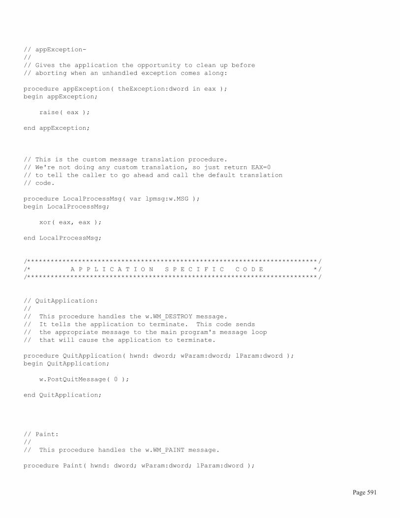
// appException-//// Gives the application the opportunity to clean up before// aborting when an unhandled exception comes along:
procedure appException( theException:dword in eax );begin appException;
raise( eax );
end appException;
// This is the custom message translation procedure.// We're not doing any custom translation, so just return EAX=0// to tell the caller to go ahead and call the default translation// code.
procedure LocalProcessMsg( var lpmsg:w.MSG ); begin LocalProcessMsg;
xor( eax, eax );
end LocalProcessMsg; /**************************************************************************//* A P P L I C A T I O N S P E C I F I C C O D E *//**************************************************************************/
// QuitApplication://// This procedure handles the w.WM_DESTROY message.// It tells the application to terminate. This code sends// the appropriate message to the main program's message loop// that will cause the application to terminate. procedure QuitApplication( hwnd: dword; wParam:dword; lParam:dword );begin QuitApplication;
w.PostQuitMessage( 0 );
end QuitApplication;
// Paint://// This procedure handles the w.WM_PAINT message.
procedure Paint( hwnd: dword; wParam:dword; lParam:dword );
Page 591

var hdc :dword; // Handle to video display device context. oldPen :dword; // Used to save the original pen. curHatch :dword; // Handle to the Hatch we're using. ps :w.PAINTSTRUCT; // Used while painting text. readonly Hatches : dword[6] := [ w.HS_HORIZONTAL, w.HS_VERTICAL, w.HS_FDIAGONAL, w.HS_BDIAGONAL, w.HS_CROSS, w.HS_DIAGCROSS ];
begin Paint;
// Message handlers must preserve EBX, ESI, and EDI. // (They've also got to preserve EBP, but HLA's procedure // entry code already does that.) push( ebx ); push( esi ); push( edi );
// Note that all GDI calls must appear within a // BeginPaint..EndPaint pair. BeginPaint( hwnd, ps, hdc );
// Draw a sequence of triangles to demonstrate // the w.StrokeAndFill API function:
for( mov( 0, esi ); esi < @elements( Hatches ); inc( esi )) do
// Select one of the six hatch styles here:
mov( Hatches[ esi*4 ], eax ); w.CreateHatchBrush( Hatches[ esi*4 ], RGB( $80, $80, $80 )); mov( eax, curHatch ); SelectObject( curHatch );
// Capture all the strokes:
w.BeginPath( hdc );
// Draw a triangle using the default pen:
intmul( 80, esi, edi ); add( 40, edi ); MoveToEx( edi, 50, NULL );
Page 592
add( 40, edi ); LineTo( edi, 50 ); LineTo( edi, 10 );
// Create a closed path // (so 'end' joins with 'start' properly):
w.CloseFigure( hdc );
w.EndPath( hdc );
// Actually draw the triangle based on the path // we've captured above:
w.StrokeAndFillPath( hdc );
// Delete the Hatch we created above:
w.DeleteObject( curHatch ); endfor;
EndPaint;
pop( edi ); pop( esi ); pop( ebx );
end Paint; end FillPaths;
7.8.3: Drawing Rectangles
After lines, perhaps the least complex graphic object that Windows will render is the rectangle. You can drawa rectangle and fill in a rectangle using the following Win32 API functions:
static
FillRect: procedure ( hDC :dword; var lprc :RECT; hbr :dword ); @stdcall; @returns( "eax" ); @external( "__imp__FillRect@12" );
FrameRect: procedure ( hDC :dword;
Page 593

var lprc :RECT; hbr :dword ); @stdcall; @returns( "eax" ); @external( "__imp__FrameRect@12" );
InvertRect: procedure ( hDC :dword; var lprc :RECT ); @stdcall; @returns( "eax" ); @external( "__imp__InvertRect@8" );
Rectangle: procedure ( hdc :dword; nLeftRect :dword; nTopRect :dword; nRightRect :dword; nBottomRect :dword ); @stdcall; @returns( "eax" ); @external( "__imp__Rectangle@20" );
These four GDI functions all have #keyword macros that are part of the BeginPaint/EndPaint (etc.) macros inthe wpa.hhf header file. The macro declarations for each of these functions follows that standard form (that is,they re similar to the Windows function, minus the hdc parameter):
FillRect( lprc, hbr );FrameRect( lprc, hbr );InvertRect( lprc );Rectangle( left, top, right bottom );
The FillRect call fills the interior of the rectangle. The lprc parameter specifies the rectangle to fill and thehbr parameter (a handle to a brush value) specifies the brush that Windows will use when filling the rectangle.Alternately, you can specify one of the standard system colors as the brush value by using the correspondingWindows constant, plus one, in place of the brush handle. For example, FillRect( someRect,w.COLOR_WINDOW+1); fills the rectangle with the standard Windows window color.
The FrameRect function draws a line around the rectangle. The lprc parameter specifies the outline of therectangle to draw and the hbr parameter is a handle to a brush that Windows will use as the pen s brush whendrawing the line around the rectangle. Like FillRect, the FrameRect function allows you to specify one of thestandard window colors in place of the brush handle if you want one of the standard, solid, colors.
The InvertRect function inverts the color of each pixel in the specified rectangle s interior.
The Rectangle function provides a quick way to draw and fill a rectangle without setting up a brush orw.RECT record. It draws the rectangle specified by the coordinates you directly pass it as parameters and it usesthe current pen to draw the outline of the rectangle, and the current device context brush to fill the rectangle.
In his first Programming Windows books, Charles Petzold introduced the Random Rectangles programthat continuously draws a set of random rectangles on the screen (much like the earlier Lines program that
Page 594

appeared in this chapter). The following code is an example of such a random rectangles program written inassembly language.
// Rectangles.hla-//// Simple Application the demonstrates line drawing.
unit Rectangles;#include( "rand.hhf" )#include( "hll.hhf" )#include( "w.hhf" )#include( "wpa.hhf" )#includeonce( "winmain.hhf" )
?@NoDisplay := true;?@NoStackAlign := true;
static ClientSizeX :int32 := 0; // Size of the client area ClientSizeY :int32 := 0; // where we can paint. readonly
ClassName :string := "RectanglesWinClass"; // Window Class Name AppCaption :string := "Rectangles Program"; // Caption for Window
// The dispatch table: // // This table is where you add new messages and message handlers // to the program. Each entry in the table must be a MsgProcPtr_t // record containing two entries: the message value (a constant, // typically one of the w.WM_***** constants found in windows.hhf) // and a pointer to a "MsgProcPtr_t" procedure that will handle the // message. Dispatch :MsgProcPtr_t; @nostorage;
MsgProcPtr_t MsgProcPtr_t:[ w.WM_DESTROY, &QuitApplication ], MsgProcPtr_t:[ w.WM_PAINT, &Paint ], MsgProcPtr_t:[ w.WM_SIZE, &Size ], // Insert new message handler records here. MsgProcPtr_t:[ 0, NULL ]; // This marks the end of the list. /**************************************************************************//* W I N M A I N S U P P O R T C O D E *//**************************************************************************/
Page 595

// initWC - We don't have any initialization to do, so just return:
procedure initWC; @noframe;begin initWC;
ret();
end initWC;
// appCreateWindow- the default window creation code is fine, so just// call defaultCreateWindow.
procedure appCreateWindow; @noframe;begin appCreateWindow;
jmp defaultCreateWindow;
end appCreateWindow;
// appException-//// Gives the application the opportunity to clean up before// aborting when an unhandled exception comes along:
procedure appException( theException:dword in eax );begin appException;
raise( eax );
end appException;
// This is the custom message translation procedure.// We're not doing any custom translation, so just return EAX=0// to tell the caller to go ahead and call the default translation// code.
procedure LocalProcessMsg( var lpmsg:w.MSG ); begin LocalProcessMsg;
xor( eax, eax );
end LocalProcessMsg;
/**************************************************************************//* A P P L I C A T I O N S P E C I F I C C O D E *//**************************************************************************/
// QuitApplication://// This procedure handles the w.WM_DESTROY message.// It tells the application to terminate. This code sends// the appropriate message to the main program's message loop
Page 596

// that will cause the application to terminate. procedure QuitApplication( hwnd: dword; wParam:dword; lParam:dword );begin QuitApplication;
w.PostQuitMessage( 0 );
end QuitApplication;
// Paint://// This procedure handles the w.WM_PAINT message.
procedure Paint( hwnd: dword; wParam:dword; lParam:dword );var hdc :dword; // Handle to video display device context ps :w.PAINTSTRUCT; // Used while painting text.
static hBrush :dword; // Brush handle. blackBrush :dword; // Handle for the stock white brush lastRGB :w.COLORREF; // Last color we used theRect :w.RECT; // Rectangle Coordinates begin Paint;
// Message handlers must preserve EBX, ESI, and EDI. // (They've also got to preserve EBP, but HLA's procedure // entry code already does that.) push( ebx ); push( esi ); push( edi ); // Get the stock black brush object so we outline the rectangles // we draw: w.GetStockObject( w.BLACK_BRUSH ); mov( eax, blackBrush ); // Note that all GDI calls must appear within a // BeginPaint..EndPaint pair. BeginPaint( hwnd, ps, hdc );
rand.range( 0, $FF_FFFF ); // Generate a random RGB value. mov( eax, lastRGB );
// Create a brush with the current color we're using:
w.CreateSolidBrush( lastRGB ); mov( eax, hBrush );
Page 597

// Draw a random rectangle using the brush we just created: rand.range( 0, ClientSizeX ); mov( eax, theRect.left ); rand.range( 0, ClientSizeY ); mov( eax, theRect.top ); mov( ClientSizeX, eax ); sub( theRect.left, eax ); rand.range( 0, eax ); mov( eax, theRect.right ); mov( ClientSizeY, eax ); sub( theRect.top, eax ); rand.range( 0, eax ); mov( eax, theRect.bottom ); FillRect( theRect, hBrush ); FrameRect( theRect, blackBrush ); // Delete the brush we created: w.DeleteObject( hBrush ); EndPaint;
// Force Windows to redraw this window without erasing // it so that we get constant feedback in the window:
w.InvalidateRect( hwnd, NULL, false ); pop( edi ); pop( esi ); pop( ebx );
end Paint;
// Size-//// This procedure handles the w.WM_SIZE message// Basically, it just saves the window's size so// the Paint procedure knows when a line goes out of// bounds.//// L.O. word of lParam contains the new X Size// H.O. word of lParam contains the new Y Size
procedure Size( hwnd: dword; wParam:dword; lParam:dword );begin Size;
// Convert new X size to 32 bits and save:
movzx( (type word lParam), eax ); mov( eax, ClientSizeX );
Page 598

// Convert new Y size to 32 bits and save:
movzx( (type word lParam[2]), eax ); mov( eax, ClientSizeY ); xor( eax, eax ); // return success.
end Size;end Rectangles;
7.8.4: Drawing Circles and Ellipses
Windows provides the w.Ellipse function for drawing circles and ellipses (a circle is a special case of anellipse, which is why there is only one function for this purpose). The calling sequence for the w.Ellipse func-tion is identical to that of the w.Rectangle API function. Because drawing circles and ellipses is not quite acommon as drawing rectangles, you don t get as wide a variety of API functions as are available for rectangles(i.e., no FrameEllipse, no FillEllipse, and no InvertEllipse functions). Nevertheless, it is possible to doeverything these functions do (for ellipses), even if it s not quite as convenient.
Here s the prototype for the w.Ellipse function:static Ellipse: procedure ( hdc :dword; nLeftRect :dword; nTopRect :dword; nRightRect :dword; nBottomRect :dword ); @stdcall; @returns( "eax" ); @external( "__imp__Ellipse@20" );
The prototype for the BeginPaint/EndPaint #keyword macro is the following:
Ellipse( LeftRect, TopRect, RightRect, BottomRect )
As usual, the Ellipse invocation macro is identical to the w.Ellipse API function with the exception that youdon t supply the device context handle as the first parameter.
The left, top, right, and bottom coordinate values you pass to the w.Ellipse function specifies abounding box that just surrounds the ellipse you want to draw (see Figure 7-13). In order to draw a circle, thebounding rectangle must be a square; that is, (bottom - top) must be equal to (right - left).
Page 599

Figure 7-13: Specifying an Ellipse with a Bounding Box
The w.Ellipse function frames the ellipse using the current device context s pen and it fills the ellipse usingthe device context s current brush value. If you want to change these values, you ll have to select a new pen orbrush into the device context before drawing an ellipse. Of course, if specifying a different pen or fill value issomething you commonly do, you might want to consider writing your own function that lets you specify thesevalues as parameters.
The following sample program, ellipses.hla, is the ellipse version of the random rectangles program of theprevious section. This program draws random ellipses to the window on a continual basis (until the user quits theprogram). One big difference between the ellipses.hla and the rectangle.hla programs is the fact that the ellipsesprogram actually draws a sequence of ellipses at each point, with each successive ellipse shrunken in a smallamount and the fill color slightly brightened for each ellipse. This creates a nice looking shade effect (of course,the program draws the ellipses so fast that it s hard to appreciate the shading, but if you look at the ellipses drawnnear the edge of the window, you ll be able to see this effect).
// Ellipses.hla-//// Simple Application the demonstrates drawing ellipses.
unit Ellipses;#include( "rand.hhf" )#include( "hll.hhf" )#include( "w.hhf" )#include( "wpa.hhf" )#includeonce( "winmain.hhf" )
?@NoDisplay := true;?@NoStackAlign := true;
static ClientSizeX :int32 := 0; // Size of the client area ClientSizeY :int32 := 0; // where we can paint.
left right
top
bottom
Page 600

readonly
ClassName :string := "EllipsesWinClass"; // Window Class Name AppCaption :string := "Ellipses Program"; // Caption for Window
// The dispatch table: // // This table is where you add new messages and message handlers // to the program. Each entry in the table must be a MsgProcPtr_t // record containing two entries: the message value (a constant, // typically one of the w.WM_***** constants found in windows.hhf) // and a pointer to a "MsgProcPtr_t" procedure that will handle the // message. Dispatch :MsgProcPtr_t; @nostorage;
MsgProcPtr_t MsgProcPtr_t:[ w.WM_DESTROY, &QuitApplication ], MsgProcPtr_t:[ w.WM_PAINT, &Paint ], MsgProcPtr_t:[ w.WM_SIZE, &Size ], // Insert new message handler records here. MsgProcPtr_t:[ 0, NULL ]; // This marks the end of the list. /**************************************************************************//* W I N M A I N S U P P O R T C O D E *//**************************************************************************/
// initWC - We don't have any initialization to do, so just return:
procedure initWC; @noframe;begin initWC;
ret();
end initWC;
// appCreateWindow- the default window creation code is fine, so just// call defaultCreateWindow.
procedure appCreateWindow; @noframe;begin appCreateWindow;
jmp defaultCreateWindow;
end appCreateWindow;
Page 601

// appException-//// Gives the application the opportunity to clean up before// aborting when an unhandled exception comes along:
procedure appException( theException:dword in eax );begin appException;
raise( eax );
end appException;
// This is the custom message translation procedure.// We're not doing any custom translation, so just return EAX=0// to tell the caller to go ahead and call the default translation// code.
procedure LocalProcessMsg( var lpmsg:w.MSG ); begin LocalProcessMsg;
xor( eax, eax );
end LocalProcessMsg; /**************************************************************************//* A P P L I C A T I O N S P E C I F I C C O D E *//**************************************************************************/
// QuitApplication://// This procedure handles the w.WM_DESTROY message.// It tells the application to terminate. This code sends// the appropriate message to the main program's message loop// that will cause the application to terminate. procedure QuitApplication( hwnd: dword; wParam:dword; lParam:dword );begin QuitApplication;
w.PostQuitMessage( 0 );
end QuitApplication;
// Paint://// This procedure handles the w.WM_PAINT message.
procedure Paint( hwnd: dword; wParam:dword; lParam:dword );var hdc :dword; // Handle to video display device context ps :w.PAINTSTRUCT; // Used while painting text.
Page 602

static hBrush :dword; // Brush handle. blackBrush :dword; // Handle for the stock white brush nullPen :dword; // Handle for the null pen. oldPen :dword; // Handle for the original pen lastRGB :w.COLORREF; // Last color we used theRect :w.RECT; // Rectangle Coordinates begin Paint;
// Message handlers must preserve EBX, ESI, and EDI. // (They've also got to preserve EBP, but HLA's procedure // entry code already does that.) push( ebx ); push( esi ); push( edi ); // Create a null pen so we don't have an outline on our ellipse: w.CreatePen( w.PS_NULL, 0, 0 ); mov( eax, nullPen ); // Get the stock black brush object so we outline the rectangles // we draw: w.GetStockObject( w.BLACK_BRUSH ); mov( eax, blackBrush ); // Note that all GDI calls must appear within a // BeginPaint..EndPaint pair. BeginPaint( hwnd, ps, hdc );
rand.range( 0, $FF_FFFF ); // Generate a random RGB value. mov( eax, lastRGB ); // Select the null pen into the context so we don't get // a black outline around the ellipse: SelectObject( nullPen ); mov( eax, oldPen );
// Create a random rectangle to surround the first ellipse // we're going to draw: rand.range( 0, ClientSizeX ); mov( eax, theRect.left ); rand.range( 0, ClientSizeY ); mov( eax, theRect.top ); mov( ClientSizeX, eax ); sub( theRect.left, eax ); rand.range( 0, eax ); add( theRect.left, eax ); mov( eax, theRect.right );
Page 603

mov( ClientSizeY, eax ); sub( theRect.top, eax ); rand.range( 0, eax ); add( theRect.top, eax ); mov( eax, theRect.bottom ); // Draw a sequence of ellipses, each successive one inside the // previous one, until the ellipse closes up on itself. forever // Create a brush with the current color we're using. // On each iteration of the loop, we'll lighten the color // a small amount so that it creates a shading effect.
w.CreateSolidBrush( lastRGB ); add( $03_0303, lastRGB ); // Lighten the color for next loop. and( $FF_FFFF, lastRGB ); mov( eax, hBrush ); SelectObject( eax ); // Draw the current ellipse: Ellipse( theRect.left, theRect.top, theRect.right, theRect.bottom ); // Shrink the Ellipse in by two pixels: add( 2, theRect.top ); add( 2, theRect.left ); sub( 2, theRect.bottom ); sub( 2, theRect.right ); // Quit the loop when the ellipse collapses on itself: mov( theRect.top, eax ); mov( theRect.left, ecx ); breakif( eax >= theRect.bottom || ecx >= theRect.right ); // Delete the brush we created: SelectObject( blackBrush ); // First, select a different brush. w.DeleteObject( hBrush );
endfor; // Restore the original pen: SelectObject( oldPen ); EndPaint;
// Force Windows to redraw this window without erasing // it so that we get constant feedback in the window:
w.InvalidateRect( hwnd, NULL, false ); pop( edi );
Page 604

pop( esi ); pop( ebx );
end Paint;
// Size-//// This procedure handles the w.WM_SIZE message// Basically, it just saves the window's size so// the Paint procedure knows when a line goes out of// bounds.//// L.O. word of lParam contains the new X Size// H.O. word of lParam contains the new Y Size
procedure Size( hwnd: dword; wParam:dword; lParam:dword );begin Size;
// Convert new X size to 32 bits and save:
movzx( (type word lParam), eax ); mov( eax, ClientSizeX );
// Convert new Y size to 32 bits and save:
movzx( (type word lParam[2]), eax ); mov( eax, ClientSizeY ); xor( eax, eax ); // return success.
end Size;end Ellipses;
7.8.5: Drawing Roundangles, Arcs, Chords, and Pies
The Windows GDI provides several additional graphic primitives that are useful for building complex graph-ical objects on the display: roundangles, arcs, chords, and pie sections. Here are the descriptions of these func-tions:static AngleArc: procedure ( hdc: dword; x: dword; y: dword; dwRadius: dword; eStartAngle:real32; eSweepAngle:real32 ); @stdcall; @returns( "eax" ); @external( "__imp__AngleArc@24" );
Page 605

// #keyword AngleArc( x, y, dwRadius, eStartAngle, eSweepAngle );
The w.AngleArc function is unique in this set insofar as it doesn t use the standard bounding box paradigmto descibe the graphical object. Instead, this particular function uses a standard definition for a circle in order todescribe the object it draws; specifically, you provide the coordinates of a center point (the x and y coordinates)and you provide a radius for the circle. This function draws a line segment and an arc. Specifically, it draws a linefrom the current pen position to the beginning of the arc and then it draws an arc along the perimeter of a circlefrom a start angle (in degrees) through the number of degrees specified by the sweep angle. The circle on whichthis function draws the arc is specified by the center point (x,y) and the radius (dwRadius) parameters. The prin-ciple purpose for this function is to draw a rounded edge that connects to line segments. This function leaves thecurrent pen position sitting at the end of the arc it draws. This function draws the arc using the current devicecontext pen setting, it does not fill the arc.
Like other GDI functions, you can only call this function while you hold a valid device context. theAngleArc macro in the wpa.hhf header file lets you easily call this function from within a BeginPaint/End-Paint sequence.
static Arc: procedure ( hdc: dword; nLeftRect: dword; nTopRect: dword; nRightRect: dword; nBottomRect: dword; nXStartArc: dword; nYStartArc: dword; nXEndArc: dword; nYEndArc: dword ); @stdcall; @returns( "eax" ); @external( "__imp__Arc@36" );
The w.Arc function (#keyword macro: Arc) lets you draw an arc along the perimeter of an ellipse. For thisfunction, you supply a standard bounding box that surrounds the ellipse on whose perimeter you want to drawthe arc. You also supply two points that are outside the bounding box. Where the line described by the startingpoint (specified by nXStartArc and nYStartArc) and the center of the ellipse intersects the perimeter of theellipse, Windows begins drawing the arc; where the line described by the ending point (nXEndArc and nYEn-
Page 606

dArc) and the center of the ellipse intersect the ellipse s perimeter, Windows stops drawing the arc (see Figure7-14).
Figure 7-14: An Arc Drawn with the w.Arc Function
ArcTo: procedure ( hdc: dword; nLeftRect: dword; nTopRect: dword; nRightRect: dword; nBottomRect: dword; nXRadial1: dword; nYRadial1: dword; nXRadial2: dword; nYRadial2: dword ); @stdcall; @returns( "eax" ); @external( "__imp__ArcTo@36" );
The w.ArcTo function is a cross between the w.AngleArc function and the w.Arc function. The parametersand geometry are identical to the w.Arc function (though the names have changed, the function still uses abounding box and two points to specify where the arc is to be drawn, just like w.Arc). Like the w.AngleArcfunction, w.ArcTo draws a line from the current pen position to the start of the arc and leaves the current penposition at the end of the arc that it draws.
static Chord: procedure ( hdc :dword;
left right
top
bottom
(nXStartArc, nYStartArc )
( nXEndArc, nYEndArc)
Page 607

nLeftRect :dword; nTopRect :dword; nRightRect :dword; nBottomRect :dword; nXRadial1 :dword; nYRadial1 :dword; nXRadial2 :dword; nYRadial2 :dword ); @stdcall; @returns( "eax" ); @external( "__imp__Chord@36" );
// #keyword Chord( left, top, right, bottom, x1, y1, x2, y2 );
A chord is a closed object that consists of an arc with a line drawn between the two endpoints of the arc (seeFigure 7-15). The chord function draws the outline of the chord using the device context s current pen and it fillsthe interior of the chord using the current device context brush.
Figure 7-15: Drawing a Chord with w.Chord
Pie: procedure ( hdc :dword; nLeftRect :dword; nTopRect :dword; nRightRect :dword;
left right
top
bottom
(nXRadial1, nYRadial1)
( nXRadial2, nYRadial2)
Outline is drawn withthe current pen
Interior is filled withthe current brush
Page 608

nBottomRect :dword; nXRadial1 :dword; nYRadial1 :dword; nXRadial2 :dword; nYRadial2 :dword ); @stdcall; @returns( "eax" ); @external( "__imp__Pie@36" );
// #keyword Pie( left, top, right, bottom, x1, y1, x2, y2 );
The w.Pie function is very similar to the w.Chord function except it draws a pie slice by filling in the areaof the ellipse between the endpoints of the arc you specify and the center of the ellipse (see Figure 7-16).
Figure 7-16: Drawing a Pie Slice with w.Pie
RoundRect: procedure ( hdc :dword; nLeftRect :dword; nTopRect :dword; nRightRect :dword; nBottomRect :dword; nWidth :dword; nHeight :dword );
left right
top
bottom
(nXRadial1, nYRadial1)
( nXRadial2, nYRadial2)
Outline is drawn withthe current pen
Interior is filled withthe current brush
Page 609

@stdcall; @returns( "eax" ); @external( "__imp__RoundRect@28" );
// #keyword RoundRect( left, top, right, bottom, width, height );
The w.RoundRect API function draws a rounded rectangle (or roundangle for short). This is a rectanglewith rounded corners. The usual bounding box specifies the outline of the rectangular portion of the image, thenWidth and nHeight parameters specify the amount of rounding that occurs at the four corners by specifying thebounds for an ellipse on each corner (see Figure 7-17).
Figure 7-17: Drawing a Rounded Rectangle using w.RoundRect
7.8.6: Bezier Curves
Bezier curves are a mathematical description of a curved line segment that models a spline (a spline is a vary-ing curve instrument that draftsmen use to create a curved line between a set of points). Windows provides twoAPI functions that you can use to draw Bezier curves:static PolyBezier: procedure ( hdc :dword; var lppt :POINT; cPoints :dword ); @stdcall; @returns( "eax" ); @external( "__imp__PolyBezier@12" );
PolyBezierTo: procedure ( hdc :dword; var lppt :POINT; cCount :dword );
nWidth
nHeight
left right
top
bottom
Page 610

@stdcall; @returns( "eax" ); @external( "__imp__PolyBezierTo@12" );
// #keyword PolyBezier( lppt, cPoints );// #keyword PolyBezierTo( lppt, cPoints );
The difference between these two functions is that w.PolyBezierTo updates the current pen position (to point atthe endpoint of the Bezier curve it draws) wherease w.PolyBezier does not affect the current pen position. Asusual for GDI drawing functions, you may only call these functions while you ve got a valid device contextopen. If you use the wpa.hhf macros (like BeginPaint/EndPaint) you can use the PolyBezier and PolyBezierTomacros to streamline calls to these API functions.
A cubic Bezier curve is defined by four points: two endpoints of a line and two control points that describehow to warp that line to form a curve. As their Poly prefix suggests, the w.PolyBezier and w.PolyBezierToAPI functions actually draw a sequence of Bezier curves (much like w.PolyLine draws a sequece of straight linesegments). The lppt parameter you supply to these functions is a pointer to an array of endpoints and controlpoints, that are organized as follows:
[initial point] [control point 1] [control point 2] [end point/start point] [control point 1] [control point 2] [end point/start point] ...
An important thing to notice here is that each endpoint is also the start point for the next Bezier curve in the list.Only the initial end point and the last endpoint in the list do not serve double duty. The cCount parameter speci-fies the total number of points found in this array. Because each Bezier curve in the list requires three points(except for the first one, which requires four points), the cCount value must be a value that, once you subtractone, is evenly divisible by three.
Generally, applications don t compute the values of the endpoints and control points for a Bezier curve inorder to draw a curved shape. Instead, most applications allow the user to specify the control and end points viasome sort of graphic editor and the program simple records those points for later playback. Therefore, it s rareto find a program that actually computes the values for the control points of a Bezier curve in order to displaysome generic curve. Nevertheless, a short demo application is called for here, just to see how you can fill in thepoints in the points array you pass to the w.PolyBezier and w.PolyBezierTo API functions. Figure 7-18 showsthe output of the bezier.hla source file (actually, this shows one possible output because the program actuallygenerates the curves in a random fashion and will generate a new display whenever you resize or otherwise forcea redraw of the window).
Page 611

Figure 7-18: Output from the Bezier.hla Program
// Bezier.hla-//// Program that demonstrates the use of the w.PolyBezier function.//// Note: this is a unit because it uses the WinMail library module that// provides a win32 main program for us.
unit Bezier;
#includeonce( "rand.hhf" )#includeonce( "hll.hhf" )#includeonce( "memory.hhf" )#includeonce( "math.hhf" )#includeonce( "w.hhf" )#includeonce( "wpa.hhf" )#includeonce( "winmain.hhf" )
?@NoDisplay := true;?@NoStackAlign := true; static ClientSizeX :int32 := 0; // Size of the client area ClientSizeY :int32 := 0; // where we can paint. readonly
ClassName :string := "BezierWinClass"; // Window Class Name
Page 612

AppCaption :string := "Bezier Program"; // Caption for Window
// The dispatch table: // // This table is where you add new messages and message handlers // to the program. Each entry in the table must be a MsgProcPtr_t // record containing two entries: the message value (a constant, // typically one of the w.WM_***** constants found in windows.hhf) // and a pointer to a "MsgProcPtr_t" procedure that will handle the // message. Dispatch :MsgProcPtr_t; @nostorage;
MsgProcPtr_t MsgProcPtr_t:[ w.WM_DESTROY, &QuitApplication ], MsgProcPtr_t:[ w.WM_PAINT, &Paint ], MsgProcPtr_t:[ w.WM_SIZE, &Size ], // Insert new message handler records here. MsgProcPtr_t:[ 0, NULL ]; // This marks the end of the list.
/**************************************************************************//* W I N M A I N S U P P O R T C O D E *//**************************************************************************/
// initWC - We don't have any initialization to do, so just return:
procedure initWC; @noframe;begin initWC;
ret();
end initWC;
// appCreateWindow- the default window creation code is fine, so just// call defaultCreateWindow.
procedure appCreateWindow; @noframe;begin appCreateWindow;
jmp defaultCreateWindow;
end appCreateWindow;
// appException-//// Gives the application the opportunity to clean up before// aborting when an unhandled exception comes along:
procedure appException( theException:dword in eax );
Page 613

begin appException;
raise( eax );
end appException;
// This is the custom message translation procedure.// We're not doing any custom translation, so just return EAX=0// to tell the caller to go ahead and call the default translation// code.
procedure LocalProcessMsg( var lpmsg:w.MSG ); begin LocalProcessMsg;
xor( eax, eax );
end LocalProcessMsg; /**************************************************************************//* A P P L I C A T I O N S P E C I F I C C O D E *//**************************************************************************/
// QuitApplication://// This procedure handles the w.WM_DESTROY message.// It tells the application to terminate. This code sends// the appropriate message to the main program's message loop// that will cause the application to terminate. procedure QuitApplication( hwnd: dword; wParam:dword; lParam:dword );begin QuitApplication;
w.PostQuitMessage( 0 );
end QuitApplication;
// Paint://// This procedure handles the w.WM_PAINT message.
procedure Paint( hwnd: dword; wParam:dword; lParam:dword );var hdc :dword; // Handle to video display device context. ps :w.PAINTSTRUCT; // Used while painting text. bzeaCurves :w.POINT[16]; // Holds five Bezier curves.
begin Paint;
Page 614

// Message handlers must preserve EBX, ESI, and EDI. // (They've also got to preserve EBP, but HLA's procedure // entry code already does that.) push( ebx ); push( esi ); push( edi ); // Fill in the bzeaCurves array with a set of end and control points: for ( mov( 0, esi ); esi < 16 * @size( w.POINT); add( @size( w.POINT ), esi ) ) do rand.range( 0, ClientSizeX ); mov( eax, (type w.POINT bzeaCurves[esi]).x ); rand.range( 0, ClientSizeY ); mov( eax, (type w.POINT bzeaCurves[esi]).y ); endfor;
// Note that all GDI calls must appear within a // BeginPaint..EndPaint pair. BeginPaint( hwnd, ps, hdc );
// Draw the curves we've created: PolyBezier( bzeaCurves, 16 );
EndPaint;
pop( edi ); pop( esi ); pop( ebx );
end Paint;
// Size-//// This procedure handles the w.WM_SIZE message// Basically, it just saves the window's size so// the Paint procedure knows when a line goes out of// bounds.//// L.O. word of lParam contains the new X Size// H.O. word of lParam contains the new Y Size
procedure Size( hwnd: dword; wParam:dword; lParam:dword );begin Size;
Page 615

// Convert new X size to 32 bits and save:
movzx( (type word lParam), eax ); mov( eax, ClientSizeX );
// Convert new Y size to 32 bits and save:
movzx( (type word lParam[2]), eax ); mov( eax, ClientSizeY ); xor( eax, eax ); // return success.
end Size; end Bezier;
7.8.7: Drawing with the Polygon Function
Windows provides an API function that draws polygons as a set of connected points. The operating of thisfunction is almost identical to w.Polyline except that Windows will automatically draw a closing line from thelast point to the first point in the list you provide (if these aren t the same point). The calling sequence and proto-types are also very similar:
static
Polygon: procedure ( hdc :dword; var lpPoints :POINT; nCount :dword ); @stdcall; @returns( "eax" ); @external( "__imp__Polygon@12" );
PolyPolygon: procedure ( hdc :dword; var lpPoints :POINT; var lpPolyCounts :var; nCount :dword ); @stdcall; @returns( "eax" ); @external( "__imp__PolyPolygon@16" );
// #keyword Polygon( lpPoints, ncount );// #keyword PolyPolygon( lpPoints, lpPolyPoints, nCount );
The w.PolyPolygon procedure draws a series of polygons (just as w.PolyPolyline draws a series of polylines). The main differences between the polyline functions and the polygon functions are that the polygon func-
Page 616

tions always create a close object (that is, they connect the endpoint and the start point) and the polygon functionfill the interior of their shapes with the current device context brush (poly line objects are not considered fillableshapes by Windows).
For the w.Polygon function, the lpPoints parameter is an array of w.POINT objects that specify the verticesof the polygon you wish to draw. The nCount parameter specifies the number of points that are in this array ofpoints. The w.Polygon function will draw lines between these points using the current device context pen andwill fill the resulting shape with the currently selected device context brush. As with all GDI drawing functions,you must have a current device context selected (and if you use the BeginPaint/EndPaint macros fromwpa.hhf, you can use the streamlined Polygon macro to invoke this function).
The w.PolyPolygon function draws a sequence of polygons whose vertices all appear in a list. ThelpPoints parameter specifies all the vertices for the polygons, the lpPolyCounts parameter is an array of inte-gers that specifies the number of points for each polygon, and the nCount parameter specifies the total number ofpolygons (i.e., the number of integer entries in the lpPolyCounts array). The lpPoints array must have thenumber of points specified by the sum of all the elements in the lpPolyCounts array. Windows does not connectthese individual polygons.
Because you can create some very complex polygonal objects, Windows offers a couple of different modesyou can specify when filling the polygon. By default, Windows uses an alternate mode. In the alternate mode,Windows fills those closed sections of the polygon that it can reach by going over an odd number of lines in theshape; any interiors you reach by traversing an even number of lines do not get filled. Sometimes, this is an inap-propriate fill behavior, so Windows also offers a winding mode that tells Windows to fill all the interior areas.You can select between these two modes by passing the w.ALTERNATE or w.WINDING constant values as theiPolyFillMode parameter to the w.SetPolyFillMode function:
static SetPolyFillMode: procedure ( hdc :dword; iPolyFillMode :dword ); @stdcall; @returns( "eax" ); @external( "__imp__SetPolyFillMode@8" );
// #keyword SetPolyFillMode( iPolyFillMode );
The following program listing demonstrates the use of the w.Polygon and w.SetPolyFillMode functions, aswell as the use of the w.ALTERNATE and w.WINDING fill modes. See Figure 7-19 for the sample output from thisprogram. The image on the left hand side of the window was drawn with the w.ALTERNATE fill style, while theobject on the right was drawn with the w.WINDING fill style.
Page 617

Figure 7-19: Output from the Polygons.hla Program
// Polygons.hla-//// Program that demonstrates the use of the w.Polygon and w.SetPolyFillMode// functions.//// Note: this is a unit because it uses the WinMail library module that// provides a win32 main program for us.
unit Polygons;
#includeonce( "rand.hhf" )#includeonce( "hll.hhf" )#includeonce( "memory.hhf" )#includeonce( "math.hhf" )#includeonce( "w.hhf" )#includeonce( "wpa.hhf" )#includeonce( "winmain.hhf" )
?@NoDisplay := true;?@NoStackAlign := true; static ClientSizeX :int32 := 0; // Size of the client area ClientSizeY :int32 := 0; // where we can paint. readonly
ClassName :string := "PolygonsWinClass"; // Window Class Name AppCaption :string := "Polygons Program"; // Caption for Window
// The dispatch table: // // This table is where you add new messages and message handlers // to the program. Each entry in the table must be a MsgProcPtr_t // record containing two entries: the message value (a constant, // typically one of the w.WM_***** constants found in windows.hhf) // and a pointer to a "MsgProcPtr_t" procedure that will handle the // message. Dispatch :MsgProcPtr_t; @nostorage;
Page 618

MsgProcPtr_t MsgProcPtr_t:[ w.WM_DESTROY, &QuitApplication ], MsgProcPtr_t:[ w.WM_PAINT, &Paint ], MsgProcPtr_t:[ w.WM_SIZE, &Size ], // Insert new message handler records here. MsgProcPtr_t:[ 0, NULL ]; // This marks the end of the list.
/**************************************************************************//* W I N M A I N S U P P O R T C O D E *//**************************************************************************/
// initWC - We don't have any initialization to do, so just return:
procedure initWC; @noframe;begin initWC;
ret();
end initWC;
// appCreateWindow- the default window creation code is fine, so just// call defaultCreateWindow.
procedure appCreateWindow; @noframe;begin appCreateWindow;
jmp defaultCreateWindow;
end appCreateWindow;
// appException-//// Gives the application the opportunity to clean up before// aborting when an unhandled exception comes along:
procedure appException( theException:dword in eax );begin appException;
raise( eax );
end appException;
/**************************************************************************//* A P P L I C A T I O N S P E C I F I C C O D E *//**************************************************************************/
// QuitApplication:
Page 619

//// This procedure handles the w.WM_DESTROY message.// It tells the application to terminate. This code sends// the appropriate message to the main program's message loop// that will cause the application to terminate. procedure QuitApplication( hwnd: dword; wParam:dword; lParam:dword );begin QuitApplication;
w.PostQuitMessage( 0 );
end QuitApplication;
// Paint://// This procedure handles the w.WM_PAINT message.
procedure Paint( hwnd: dword; wParam:dword; lParam:dword );var hdc :dword; // Handle to video display device context. ps :w.PAINTSTRUCT; // Used while painting text. windingPoly :w.POINT[8]; // Holds the points for two overlapping rects. alterPoly :w.POINT[8]; // Holds the points for two overlapping rects. #macro index(i); (i*@size(w.POINT)) #endmacro
begin Paint;
// Message handlers must preserve EBX, ESI, and EDI. // (They've also got to preserve EBP, but HLA's procedure // entry code already does that.) push( ebx ); push( esi ); push( edi ); // Fill in the polygon array to form two overlapping rectangles: mov( 0, windingPoly.x[ index(7) ] ); mov( ClientSizeX, eax ); shr( 2, eax ); // 1/4 of the window's width mov( eax, windingPoly.x[ index(5) ] ); mov( eax, ecx ); shr( 1, eax ); // 1/8 of the window width mov( eax, windingPoly.x[ index(0) ] ); mov( eax, windingPoly.x[ index(3) ] ); mov( eax, windingPoly.x[ index(4) ] ); mov( eax, windingPoly.x[ index(6) ] );
Page 620
add( ecx, eax ); // 3/8 of the window's width mov( eax, windingPoly.x[ index(1) ] ); mov( eax, windingPoly.x[ index(2) ] ); mov( 5, eax ); mov( eax, windingPoly.y[ index(0) ] ); mov( eax, windingPoly.y[ index(1) ] ); mov( eax, windingPoly.y[ index(4) ] );
mov( ClientSizeY, eax ); shr( 1, eax ); mov( eax, ecx ); shr( 1, ecx ); add( ecx, eax ); // 3/4 of ClientSizeY mov( eax, windingPoly.y[ index(2) ] ); mov( eax, windingPoly.y[ index(3) ] ); mov( eax, windingPoly.y[ index(6) ] ); shr( 1, eax ); // 3/8 of ClientSizeY mov( eax, windingPoly.y[ index(5) ] ); mov( eax, windingPoly.y[ index(7) ] );
// Create the alterPoly array here by offseting the // winding polygon by half the screen: mov( ClientSizeX, ecx ); shr( 1, ecx ); for( xor( esi, esi ); esi < 8; inc( esi )) do mov( windingPoly.x[ esi*8], eax ); add( ecx, eax ); mov( eax, alterPoly.x[ esi*8 ] ); mov( windingPoly.y[ esi*8], eax ); mov( eax, alterPoly.y[ esi*8 ] ); endfor;
// Note that all GDI calls must appear within a // BeginPaint..EndPaint pair. BeginPaint( hwnd, ps, hdc );
SelectObject( w.GetStockObject( w.GRAY_BRUSH )); // Draw the curves we've created: SetPolyFillMode( w.ALTERNATE ); Polygon( windingPoly, 8 ); SetPolyFillMode( w.WINDING ); Polygon( alterPoly, 8 );
Page 621

EndPaint;
pop( edi ); pop( esi ); pop( ebx );
end Paint;
// Size-//// This procedure handles the w.WM_SIZE message// Basically, it just saves the window's size so// the Paint procedure knows when a line goes out of// bounds.//// L.O. word of lParam contains the new X Size// H.O. word of lParam contains the new Y Size
procedure Size( hwnd: dword; wParam:dword; lParam:dword );begin Size;
// Convert new X size to 32 bits and save:
movzx( (type word lParam), eax ); mov( eax, ClientSizeX );
// Convert new Y size to 32 bits and save:
movzx( (type word lParam[2]), eax ); mov( eax, ClientSizeY ); xor( eax, eax ); // return success.
end Size; end Polygons;
7.9: Regions
A region in Windows is an area that is defined using rectangles, roundangles (rounded rectangles), ellipses,and polygons. While you can use regions for many different purposes in Windows, their primary purposes are tosupport masking (or clipping) when drawing objects to the display and creating specialized objects to draw orfill. We ll take a look at drawing complex regions in this section and look at clipping in the next section.
Windows regions provide a mechanism for merging two distinct objects into a single shape. For example,consider the overlapping rectangles produced by the Polygons.hla program of the previous section (see Figure7-20). Unless you fill this object with a very dark (e.g., black) brush, it s pretty obivious that what we have hereare two rectangles rather than a single object. Perhaps you really wanted to create the shape that Figure 7-21shows (for the time being, we ll ignore the fact that we can easily create this new shape as a polygon, indeed withless work than creating the overlapping rectangles from Polygons.hla; use your imagination and assume that this
Page 622

is a complex shape). Well, Windows region facilities provide a way to combine (or merge) two separate shapes,producing a new, distinct shape.
Figure 7-20: The Overlapping Rectangles that Polygon.hla Produces
Figure 7-21: A Desired Shape
To create a simple region, you use one of the followingWindows API functions:static
CreateEllipticRgn: procedure ( nLeftRect :dword; nTopRect :dword; nRightRect :dword; nBottomRect :dword ); @stdcall; @returns( "eax" ); @external( "__imp__CreateEllipticRgn@16" );
CreateEllipticRgnIndirect: procedure ( var lprc :RECT ); @stdcall; @returns( "eax" ); @external( "__imp__CreateEllipticRgnIndirect@4" );
CreatePolyPolygonRgn: procedure ( var lppt :POINT; var lpPolyCounts :dword; nCount :dword;
Page 623

fnPolyFillMode :dword ); @stdcall; @returns( "eax" ); @external( "__imp__CreatePolyPolygonRgn@16" );
CreatePolygonRgn: procedure ( var lppt :POINT; cPoints :dword; fnPolyFillMode :dword ); @stdcall; @returns( "eax" ); @external( "__imp__CreatePolygonRgn@12" );
CreateRectRgn: procedure ( nLeftRect :dword; nTopRect :dword; nRightRect :dword; nBottomRect :dword ); @stdcall; @returns( "eax" ); @external( "__imp__CreateRectRgn@16" );
CreateRectRgnIndirect: procedure ( VAR lprc :RECT ); @stdcall; @returns( "eax" ); @external( "__imp__CreateRectRgnIndirect@4" );
CreateRoundRectRgn: procedure ( nLeftRect :dword; nTopRect :dword; nRightRect :dword; nBottomRect :dword; nWidthEllipse :dword; nHeightEllipse :dword ); @stdcall; @returns( "eax" ); @external( "__imp__CreateRoundRectRgn@24" );
These calls have the same parameters as the w.Rectangle, w.RoundRect, w.Ellipse, w.Polygon, andw.PolyPolygon API functions. However, instead of rendering one of these objects, these functions create aregion. The indirect versions let you pass a bounding rectangle that defines the shape of the object from whichWindows will create a region.
A region is an internal Windows resource. When you create a region with one of these calls, Windows willconstruct an internal data structure to represent that region and return a handle (in EAX) that you can use to referto that structure. Like all GDI resources you create, you must make sure that you delete any region objects you
Page 624

create before your application quits. If you don t, those regions will continue to consume Windows resources.Therefore, it s important for you to save the handle that Windows returns from these functions so you can deletethe resource later.
You can also change an existing region to a simple rectangular region via the API function:
SetRectRgn: procedure ( hrgn :dword; nLeftRect :dword; nTopRect :dword; nRightRect :dword; nBottomRect :dword ); @stdcall; @returns( "eax" ); @external( "__imp__SetRectRgn@20" );
This function does not return a handle (it modifies the region whose handle you pass to this function). Instead,this function simply returns success/error in EAX.
The real power behind regions only becomes apparent when you consider the w.CombineRgn API function:
static
CombineRgn: procedure ( hrgnDest :dword; hrgnSrc1 :dword; hrgnSrc2 :dword; fnCombineMode :dword ); @stdcall; @returns( "eax" ); @external( "__imp__CombineRgn@16" );
The first three parameters must be handles of valid regions that you ve previously created (this is even truefor the hrgnDest parameter, which w.CombineRgn will destroy before creating a new region by combining thesecond two parameters - weird semantics, but this is the way Windows works). This function combines the tworegions specified by the hrgnSrc1 and hrgnSrc2 parameter using the combine mode specified by the fourthparameter (fnCombineMode); this function creates a new region and replaces the hrgnDest region by this newregion. The hrgnDest parameter supports the modes described in Table 7-6.
Table 7-6: fnCombineMode Values for w.CombineRgn
fnCombine How w.CombineRgn Creates the new Region
w.RGN_AND The new region is the intersection of the source regions (i.e., the portions of the source regions that overlap).
w.RGN_OR The new region is the union of the two source regions (i.e., all the area described by both regions).
Page 625

Once you ve created a region, you can draw and fill that region in the current device context. Here are thefunctions you can use to render regions:
static
FillRgn: procedure ( hdc :dword; hrgn :dword; hbr :dword ); @stdcall; @returns( "eax" ); @external( "__imp__FillRgn@12" );
// #keyword FillRgn( hrgn, hbr );
The w.FillRgn function fills a region (passed as the hrgn parameter) using the brush you pass as a parameter).Like all GDI drawing routines, you must have a valid device context before calling this routine.
static FrameRgn: procedure ( hdc :dword; hrgn :dword; hbr :dword; nWidth :dword; nHeight :dword ); @stdcall; @returns( "eax" ); @external( "__imp__FrameRgn@20" );
// #keyword FrameRgn( hrgn, hbr, nWidth, nHeight );
The w.FrameRgn function draws an outline around a region. The hrgn parameter specifies the region to frame,the hbr parameter specifies the handle of a brush to use when drawing the outline, the nWidth parameter speci-fies the width, in logical units, of vertical brush strokes, and the nHeight parameter specifies the height of hori-zontal brush strokes.
static InvertRgn: procedure
w.RGN_XOR The new region is the union of the two source regions, minus any overlap between the two regions.
w.RGN_DIFF The new region is all of the area in the first source region that is not also in the second source region.
w.RGN_COPY The new region is all of the first source region, ignoring the second source region.
fnCombine How w.CombineRgn Creates the new Region
Page 626

( hdc :dword; hrgn :dword ); @stdcall; @returns( "eax" ); @external( "__imp__InvertRgn@8" );
// #keyword InvertRgn( hrgn );
The w.InvertRgn function inverts the colors within the region specified by the handle you pass this function.
static PaintRgn: procedure ( hdc :dword; hrgn :dword ); @stdcall; @returns( "eax" ); @external( "__imp__PaintRgn@8" );
// #keyword PaintRgn( hrgn );
The w.PaintRgn is very similar to w.FillRgn. The difference is that w.PaintRgn fills the region using the cur-rently selected brush in the device context (as opposed to w.FillRgn, to whom you pass a brush handle).
In addition to the functions that frame and paint regions, there are several additional utility functions that areuseful when using regions:
static EqualRgn: procedure ( hSrcRgn1 :dword; hSrcRgn2 :dword ); @stdcall; @returns( "eax" ); @external( "__imp__EqualRgn@8" );
The w.EqualRgn function returns true (non-zero) in EAX if the two regions are identical in size and shape. Itreturns false (zero) otherwise.
static GetRgnBox: procedure ( hrgn :dword; var lprc :RECT ); @stdcall; @returns( "eax" ); @external( "__imp__GetRgnBox@8" );
Page 627

The w.GetRgnBox function stores the coordinates of a bounding box that surrounds the region whose handle youpass as the first parameter. The second parameter, lprc, receives the bounding rectangle. The return value inEAX specifies the type of the region, it is one of the values in Table 7-7.
Table 7-7: w.GetRgnBox Return Values
static OffsetRgn: procedure ( hrgn :dword; nXOffset :dword; nYOffset :dword ); @stdcall; @returns( "eax" ); @external( "__imp__OffsetRgn@12" );
The w.OffsetRgn function API function adds the nXOffset and nYOffset values to the region coordinates,moving the region by the specified amount. Note that these are signed integer values (despite the declaration tothe contrary) and you can move the image up, down, left, or right by an appropriate amount by specifying posi-tive and negative numbers.
static PtInRegion: procedure ( hrgn :dword; X :dword; Y :dword ); @stdcall; @returns( "eax" ); @external( "__imp__PtInRegion@12" );
The w.PtInRegion function returns true (non-zero) in EAX if the point specified by the (X,Y) parameters iswithin the region whose handle you pass as the hrgn parameter. This function returns false (zero) if the point isoutside the region.
static RectInRegion: procedure ( hrgn :dword; var lprc :RECT );
Value Returned in EAX Description
w.NULLREGION Region is empty.
w.SIMPLEREGION Region is a simple rectangle
w.COMPLEXREGION Region is a complex object that is more than a single rectangle.
Page 628

@stdcall; @returns( "eax" ); @external( "__imp__RectInRegion@8" );
The w.RectInRegion function returns true (non-zero) or false (zero) in EAX depending upon whether any partof the rectangle you specify via the lprc parameter is within the region whose handle you pass as the hrgnparameter. Note that this function returns false only if the rectangle is completely outside the region.
7.10: Clipping
The second primary use for regions is to support clipping under Windows. You can use a region as a mask, ortemplate, that protects portions of the client area of your window when drawing to that window. To use a regionas a clipping region, you simply select the region into a device context. From that point forward, Windows willonly allow you to draw within the area described by that region. You can select a region you ve created into thecurrent device context by using either of the following two functions:
static SelectObject: procedure ( hdc :dword; hgdiobj :dword ); @stdcall; @returns( "eax" ); @external( "__imp__SelectObject@8" );
// #keyword SelectObject( hgdiobj ); // use a region handle for clipping!
SelectClipRgn: procedure ( hdc :dword; hrgn :dword ); @stdcall; @returns( "eax" ); @external( "__imp__SelectClipRgn@8" );
// #keyword SelectClipRegion( hrgn );
Once you execute w.SelectObject or w.SelectClipRegion, then all future output to the current device contextis limited to the region whose handle you pass as the hrgn or hgdiobj parameter.
Charles Petzold s Windows Programming book has another cute example worth repeating here: the clo-ver application. This program demonstrates clipping in elliptical regions by creating four overlapping ellipticalregions, combining them, and then using them as a clipping region for the application s window. Once the clip-ping region is set up, the program draws a serials a radial lines from the center of the screen towards the outeredges. The following clover.hla program is an HLA adaptation of this idea. Figure shows the output for this pro-gram.
Page 629

Figure 7-22: Output from the Clover.hla Program
// Clover.hla-//// Program that demonstrates the use of the clipping by drawing a// simple "Clover" pattern.//// Note: this is a unit because it uses the WinMail library module that// provides a win32 main program for us.
unit Clover;
#includeonce( "rand.hhf" )#includeonce( "hll.hhf" )#includeonce( "memory.hhf" )#includeonce( "math.hhf" )#includeonce( "w.hhf" )#includeonce( "wpa.hhf" )#includeonce( "winmain.hhf" )
?@NoDisplay := true;?@NoStackAlign := true; static ClientSizeX :int32 := 0; // Size of the client area ClientSizeY :int32 := 0; // where we can paint. readonly
ClassName :string := "CloverWinClass"; // Window Class Name AppCaption :string := "Clover Program"; // Caption for Window
// The dispatch table: // // This table is where you add new messages and message handlers // to the program. Each entry in the table must be a MsgProcPtr_t
Page 630

// record containing two entries: the message value (a constant, // typically one of the w.WM_***** constants found in windows.hhf) // and a pointer to a "MsgProcPtr_t" procedure that will handle the // message. Dispatch :MsgProcPtr_t; @nostorage;
MsgProcPtr_t MsgProcPtr_t:[ w.WM_DESTROY, &QuitApplication ], MsgProcPtr_t:[ w.WM_PAINT, &Paint ], MsgProcPtr_t:[ w.WM_SIZE, &Size ], // Insert new message handler records here. MsgProcPtr_t:[ 0, NULL ]; // This marks the end of the list.
/**************************************************************************//* W I N M A I N S U P P O R T C O D E *//**************************************************************************/
// initWC - We don't have any initialization to do, so just return:
procedure initWC; @noframe;begin initWC;
ret();
end initWC;
// appCreateWindow- the default window creation code is fine, so just// call defaultCreateWindow.
procedure appCreateWindow; @noframe;begin appCreateWindow;
jmp defaultCreateWindow;
end appCreateWindow;
// appException-//// Gives the application the opportunity to clean up before// aborting when an unhandled exception comes along:
procedure appException( theException:dword in eax );begin appException;
raise( eax );
end appException;
Page 631

// This is the custom message translation procedure.// We're not doing any custom translation, so just return EAX=0// to tell the caller to go ahead and call the default translation// code.
procedure LocalProcessMsg( var lpmsg:w.MSG ); begin LocalProcessMsg;
xor( eax, eax );
end LocalProcessMsg; /**************************************************************************//* A P P L I C A T I O N S P E C I F I C C O D E *//**************************************************************************/
// QuitApplication://// This procedure handles the w.WM_DESTROY message.// It tells the application to terminate. This code sends// the appropriate message to the main program's message loop// that will cause the application to terminate. procedure QuitApplication( hwnd: dword; wParam:dword; lParam:dword );begin QuitApplication;
w.PostQuitMessage( 0 );
end QuitApplication;
// Paint://// This procedure handles the w.WM_PAINT message.
procedure Paint( hwnd: dword; wParam:dword; lParam:dword );var hdc :dword; // Handle to video display device context. ps :w.PAINTSTRUCT; // Used while painting text. leafs :dword[4]; // Handles for our four-leaf clover Clover :dword; // Four-leaf clover region handle. temp1 :dword; temp2 :dword; x :dword; y :dword;
begin Paint;
// Message handlers must preserve EBX, ESI, and EDI. // (They've also got to preserve EBP, but HLA's procedure // entry code already does that.)
Page 632

push( ebx ); push( esi ); push( edi ); // Create the four regions we're going to use as a mask: // Region one - ellipse specified by (0, y/4):(x/2, y*3/4) mov( ClientSizeX, esi ); shr( 1, esi ); // 1/2 ClientSizeX mov( ClientSizeY, edi ); shr( 1, edi ); // 1/2 ClientSizeY mov( edi, eax ); shr( 1, eax ); // 1/4 ClientSizeY add( eax, edi ); // 3/4 ClientSizeY w.CreateEllipticRgn( 0, eax, esi, edi ); mov( eax, leafs[0*4] ); // Region two - ellipse specified by (x/2, y/4):(x, y*3/4) mov( ClientSizeY, edi ); shr( 1, edi ); // 1/2 ClientSizeY mov( edi, eax ); shr( 1, eax ); // 1/4 ClientSizeY add( eax, edi ); // 3/4 ClientSizeY w.CreateEllipticRgn( esi, eax, ClientSizeX, edi ); mov( eax, leafs[1*4] ); // Region three - ellipse specified by (x/4, 0):(x*3/4, y/2) mov( ClientSizeY, esi ); shr( 1, esi ); // 1/2 ClientSizeY mov( ClientSizeX, edi ); shr( 1, edi ); // 1/2 ClientSizeX mov( edi, eax ); shr( 1, eax ); // 1/4 ClientSizeX add( eax, edi ); // 3/4 ClientSizeX w.CreateEllipticRgn( eax, 0, edi, esi ); mov( eax, leafs[2*4] ); // Region four - ellipse specified by (x/4, y/2):(x*3/4, y) mov( ClientSizeX, edi ); shr( 1, edi ); // 1/2 ClientSizeX mov( edi, eax ); shr( 1, eax ); // 1/4 ClientSizeX add( eax, edi ); // 3/4 ClientSizeX w.CreateEllipticRgn( eax, esi, edi, ClientSizeY ); mov( eax, leafs[3*4] );
Page 633

// Combine the regions using the XOR combination: w.CreateRectRgn( 0, 0, 0, 0 ); mov( eax, temp1 ); w.CreateRectRgn( 0, 0, 0, 0 ); mov( eax, temp2 ); w.CreateRectRgn( 0, 0, 0, 0 ); mov( eax, Clover ); w.CombineRgn( temp1, leafs[0*4], leafs[1*4], w.RGN_OR ); w.CombineRgn( temp2, leafs[2*4], leafs[3*4], w.RGN_OR ); w.CombineRgn( Clover, temp1, temp2, w.RGN_XOR );
// Note that all GDI calls must appear within a // BeginPaint..EndPaint pair. BeginPaint( hwnd, ps, hdc );
// Select the Clover region in to use as our clipping rectangle: w.SelectClipRgn( hdc, Clover ); // Now draw a sequence of lines from the center of the display // to the edges in order to demonstrate the clipping: mov( ClientSizeX, eax ); // Compute the coordinate of the shr( 1, eax ); // screen's center point. mov( eax, x ); mov( ClientSizeY, eax ); shr( 1, eax ); mov( eax, y ); // Draw the lines that intersect the top of the window: for( mov( 0, esi ); esi < ClientSizeX; add( 4, esi )) do MoveToEx( x, y, NULL ); LineTo( esi, 0 ); endfor; // Draw the lines that intersect the right side of the window: for( mov( 0, esi ); esi < ClientSizeY; add( 4, esi )) do MoveToEx( x, y, NULL ); LineTo( ClientSizeX, esi ); endfor; // Draw the lines that intersect the bottom of the window: for( mov( 0, esi ); esi < ClientSizeX; add( 4, esi )) do MoveToEx( x, y, NULL ); LineTo( esi, ClientSizeY );
Page 634

endfor; // Draw the lines that intersect the left side of the window: for( mov( 0, esi ); esi < ClientSizeY; add( 4, esi )) do MoveToEx( x, y, NULL ); LineTo( 0, esi ); endfor; EndPaint;
pop( edi ); pop( esi ); pop( ebx );
end Paint;
// Size-//// This procedure handles the w.WM_SIZE message// Basically, it just saves the window's size so// the Paint procedure knows when a line goes out of// bounds.//// L.O. word of lParam contains the new X Size// H.O. word of lParam contains the new Y Size
procedure Size( hwnd: dword; wParam:dword; lParam:dword );begin Size;
// Convert new X size to 32 bits and save:
movzx( (type word lParam), eax ); mov( eax, ClientSizeX );
// Convert new Y size to 32 bits and save:
movzx( (type word lParam[2]), eax ); mov( eax, ClientSizeY ); xor( eax, eax ); // return success.
end Size; end Clover;
Page 635

7.11: Bitmaps
Bitmaps are probably the most common thing that people recognize as graphic images. A bit map is atwo-dimensional array of pixels that Windows can render on the screen. Digital photographs, icons, and cursorsare good examples of typical bitmaps in a Windows system. In this section, we ll explore ways to create and dis-play bitmaps on a device context.
Unfortunately, dealing with bitmaps is not a trivial process. Bitmaps, because of their pixel nature, are some-what device dependent. Indeed, the earliest versions of Windows only supported device-dependent bitmapsmeaning that if you move a graphic image represented by a bitmap from one machine to the next you might getsome spectacularly weird results. Later versions of Windows support device independent bitmaps but thisdevice independence comes at a price - complexity. Working with device independent bitmaps is definitely a lotmore work than dealing with device dependent bitmaps. Nevertheless, device independence is the only way togo, so you re going to have to deal with the additional complexity with working with bitmaps.
Device independent bitmaps, or DIBs as they are known in Windows terminology, is a well-defined file for-mat. Indeed, the .BMP suffix that programs like Windows Paint uses indicate a DIB format. Windows, itself,doesn t actually work with the DIB file format. Instead, you ve got to convert a DIB format to a device depen-dent format in order to display the DIB.
A DIB begins with the device independent bitmap file header. This is a record, named w.BITMAPFILE-HEADER, that takes the following form:type BITMAPFILEHEADER: record bfType: word; bfSize: dword; bfReserved1: word; bfReserved2: word; bfOffBits: dword; endrecord;
The bfType field always contains BM (for bitmap). The bfSize field specifies the total size of the bitmapfile. The bfOffBits file specifies the offset, in bytes, from the beginnig of the file to the actual bitmap data. Theother two fields are reserved and will be set to zero.
The bitmap file header is followed by another record of type w.BITMAPINFOHEADER that takes the followingform:
type BITMAPINFOHEADER: record biSize: dword; biWidth: dword; biHeight: dword; biPlanes: word; biBitCount: word; biCompression: dword; biSizeImage: dword; biXPelsPerMeter: dword; biYPelsPerMeter: dword; biClrUsed: dword; biClrImportant: dword; endrecord;
Page 636

The biSize field contains the size of the w.BITMAPINFOHEADER, in bytes. This field exists to allowchanges to this structure format in the future (the application can use this field to detemine how many fields arepresent in the bitmap info header record). Examples of such extensions are the w.BITMAPV4HEADER andw.BITMAPV5HEADER records used by win95 and win2K/win98, respectively:
type BITMAPV4HEADER: record bV4Size: dword; bV4Width: dword; bV4Height: dword; bV4Planes: word; bV4BitCount: word; bV4V4Compression: dword; bV4SizeImage: dword; bV4XPelsPerMeter: dword; bV4YPelsPerMeter: dword; bV4ClrUsed: dword; bV4ClrImportant: dword; bV4RedMask: dword; bV4GreenMask: dword; bV4BlueMask: dword; bV4AlphaMask: dword; bV4CSType: dword; bV4Endpoints: CIEXYZTRIPLE; bV4GammaRed: dword; bV4GammaGreen: dword; bV4GammaBlue: dword; endrecord;
BITMAPV5HEADER: record bV5Size: dword; bV5Width: dword; bV5Height: dword; bV5Planes: word; bV5BitCount: word; bV5V4Compression: dword; bV5SizeImage: dword; bV5XPelsPerMeter: dword; bV5YPelsPerMeter: dword; bV5ClrUsed: dword; bV5ClrImportant: dword; bV5RedMask: dword; bV5GreenMask: dword; bV5BlueMask: dword; bV5AlphaMask: dword; bV5CSType: dword; bV5Endpoints: CIEXYZTRIPLE; bV5GammaRed: dword; bV5GammaGreen: dword; bV5GammaBlue: dword; bV5Intent:dword; bV5ProfileData:dword; bV5ProfileSize:dword;
Page 637

bV5Reserved:dword; endrecord;
The biWidth and biHeight fields specify the width and height of the bitmap, in pixels, respective.
The biPlanes field is always set to one on modern machines (this is device dependent information for reallyold video display cards).
The biBitCount field specifies the number of bits per pixel used to specify the number of colors. This fieldwill contain 1, 4, 8, 16, or 24.
The biCompression field specifies whether this bitmap uses data compression. It will contain zero for nocompression. Windows supports no compression, run length encoding, JPEG, and PNG compression formats.Compressed bitmaps are beyond the scope of these book and we won t consider them here. Please see theMicrosoft documentation for more details. The biSizeImage contains the size of the bitmap image if compres-sion is in use. This field can be set to zero if you re not using compression.
The biXPelsPerMeter and biYPelsPerMeter specifies the expected display resolution in pixels per meter.
The biClrUsed field specifies thenumber of colors that the image uses and the biClrImportant field speci-fies the minimum number of colors that should be used to properly display the image. If the biClrUsed field iszero and the biBitCount field is 1, 4, or 8, then a set of two, 16, or 256 RGB values immediately follow thew.BITMAPINFOHEADER record. These RGB values specify the palette to use when drawing the bitmap image. Ifthe biClrUsed field is non-zero, then this field specifies how many RGB values immediately follow the w.BIT-MAPINFOHEADER record.
Note that the fields beyond biBitCount are optional. The biSize field s value determines if these fields areactually present in the bitmap info header. Therefore, you must explicitly check the value of biSize beforeaccessing these fields. If a field is not present, you can assume its value is zero or any other reasonable defaultvalue you want to use.
Immediately following the set of RGB values (if any) comes the bitmap itself. The first byte of the bitmapdata corresponds to the lower left hand corner of the image to be rendered. Successive bits in the bitmap corre-spond to pixels appearing to the right and, upon hitting the end of a row, lines of pixels appearing above the cur-rent line.
For a monocrhome bitmap, where there is one bit per pixel, the pixels are packed into the bytes such that thehigh order bit of a byte is the first pixel to be drawn, bit six of a byte is the pixel just to the right of the H.O. pixel,and so on down to the L.O. bit. Upon crossing a byte boundary, the process repeats again with the H.O. bit.
For a 16-color (four-bit) bitmap, the H.O. four bits of the first byte correspond to the first pixel on the display(in the lower left hand corner), the L.O. four bits of the first byte correspond to the second pixel on the display,and so on.
For an eight-bit (256 color) bitmap, each byte corresponds to a single pixel. For 16-bit bitmaps, a pair ofbytes constitutes each pixel. For 24-bit bitmaps, a set of three bytes is used for each pixel.
Every row in a bitmap, no matter what the actual width in pixels of the bitmap happens to be, is padded withzero to ensure that each row is a multiple of four bytes long.
Creating and drawing a bitmap is a relatively straight-forward process. The first step is to fill in a w.BITMAP-INFOHEADER structure and use this structure to create a device independent bitmap. Windows actually providesseveral was of creating the bitmap, a simple one is:
static CreateDIBitmap: procedure ( hdc :dword;
Page 638

var lpbmih :BITMAPINFOHEADER; fdwInit :dword; var lpbInit :var; var lpbmi :BITMAPINFO; fuUsage :dword ); @stdcall; @returns( "eax" ); @external( "__imp__CreateDIBitmap@24" );
// #keyword CreateDIBitmap( lpbmih, fdwInit, lpbInit, lpbmi, fuUsage );
The hdc parameter (which is typically your display device context) provides a template from which Windowswill extract several default values for the bitmap. For example, the bitmap will have the same number of colorsas the device context whose handle you supply as the first parameter. In general, if you intend to render the bit-map on your display, you should supply the display s device context handle here.
The second parameter, lpbmih, is a pointer to a w.BITMAPINFOHEADER record object. Windows extracts thebitmap information from this object.
The fdwInit parameter is either zero or should contain the value w.CBM_INIT. If this field is zero, thenw.CreateDIBitmap ignores the lpbInit and lpbmi parameters. If this field contains w.CBM_INIT then thew.CreateDIBitmap function uses the values in these two parameters (see the descriptions that follow).
If the fdwInit parameter has the value w.CBM_INIT, then Windows will use the data found at the addresspassed in lpbInit as the initial set of bits for the bitmap data. The format of this data depends upon the valuesfound in the w.BITMAPINFOHEADER pointer passed in the lpbmih parameter. See the description given earlier fordetails.
If the fdwInit parameter has the value w.CBM_INIT, then the lpbmi parameter contains the address of aw.BITMAPINFO record that specifies the color information for the initial bitmap. The w.BITMAPINFO record takesthe following form:type BITMAPINFO: record bmiHeader: BITMAPINFOHEADER; bmiColors: RGBQUAD; // This is an array, bounds specified by bimHeader. endrecord;
The fuUsage parameter should contain zero (technically, it should contain the constant w.DIB_RGB_COLORS,but this happens to be the value zero). See the Microsoft documentation for more details on this parameter svalue.
Once you create a bitmap with w.CreateDIBitmap, there really isn t a whole lot you can do with it. Thisfunction returns a handle to the bitmap, but that bitmap is internal to Windows, so you cannot play around with itdirectly. In order to manipulate the bitmap, you ve got to create a memory-based device context and select thebitmap into this new device context. You can create a memory-based device context using the w.CreateCompat-ibleDC function:
static CreateCompatibleDC: procedure ( hdc :dword ); @stdcall;
Page 639

@returns( "eax" ); @external( "__imp__CreateCompatibleDC@4" );
This function requires a handle to an existing device context (e.g., your display context) and it will create a new,memory-based, device context with the same attributes as the device context whose handle you pass as theparameter. For example, if you pass your application window s device context handle as the parameter, the mem-ory-based device context this function creates will have the same attributes (e.g., number of colors and size) asthe application s window. Because you re probably going to render the bitmap you re creating directly in theapplication s window, it s not a bad idea for your memory-based device context to have the same attributes.
Okay, so what exactly does memory-based device context mean, anyway? Well, quite literally, this meansthat Windows uses system RAM to maintain the image you draw. It isn t connect to any display output device, soyou can t see what you ve draw to a memory-based device context, but beyond this minor point a memory-baseddevice context is identical to a standard device context. Of course, if you can t see what s in a memory-baseddevice context, you might wonder why anyone would want to use it. Well, as it turns out, although you cannotdirectly view what is written to a memory-based device context, you can copy part or all of a memory-baseddevice context to some other device context (e.g., your window s device context).
The w.CreateCompatibleDC function returns a handle to the device context it creates. You will use this han-dle to refer to the bitmap object you re creating. Also, don t forget that device contexts are resources and youmust delete system resources when you are done using them. In particular, you will need to call w.DeleteDC todelete the device context from memory when you are finished with the device context, else you ll cause aresourceleak inside Windows.
Once you ve created a bitmap with w.CreateDIBitmap and you ve created a device context with w.Create-CompatibleDC, the next step is to connect the two by selecting the bitmap into the device context. You accom-plish this using the w.SelectObject function, e.g.,
w.SelectObject( memDeviceContextHandle, bitmapHandle );
When you first create a device context via w.CreateCompatibleDC, Windows sets aside a 1x1 pixel drawingarea for that device context. This isn t large enough to do anything of interest. Selecting a bitmap into the devicecontext expands the drawing canvas for that device context (that is, it uses the bitmap you ve selected as thedrawing area). This is specifically why we created a bitmap in the first place, to define the drawing area for useby the device context.
After selecting the bitmap into the memory-based device context, you can write to that device context usingthenormal GDI drawing commands and everything you draw will wind up in the bitmap you ve created. Notethat because you re not using the application s standard Window device context, you cannot use the Begin-Paint/EndPaint macros found in the wpa.hhf header file. Instead, you ll have to call the Win32 API drawingfunctions directly and pass them your memory-based device context s handle.
The last piece in the puzzle is how do we transfer our bitmap from the memory-based device context to thewindow s device context? Well, this is accomplished using Windows bitblt operations (bitblt, pronounced bitblit standards for bit block transfer ). Two very useful functions in this category are w.BitBlt andw.StretchBlt:
static BitBlt: procedure ( hdcDest :dword; nXDest :dword; nYDest :dword;
Page 640

nWidth :dword; nHeight :dword; hdcSrc :dword; nXSrc :dword; nYSrc :dword; dwRop :dword ); @stdcall; @returns( "eax" ); @external( "__imp__BitBlt@36" );
StretchBlt: procedure ( hdcDest :dword; nXOriginDest :dword; nYOriginDest :dword; nWidthDest :dword; nHeightDest :dword; hdcSrc :dword; nXSrc :dword; nYSrc :dword; nWidthSrc :dword; nHeightSrc :dword; dwRop :dword ); @stdcall; @returns( "eax" ); @external( "__imp__StretchBlt@44" );
The w.BitBlt API function copies a set of pixels from one device context to another. The hdcDest parame-ter specifies the target device context (e.g., your application window s device context). The nXDest, nYDest,nWidth, and nHeight parameter specify the location and size of the bitmap when w.BitBlt draws it to thedevice context. Note that this function will not scale the bitmap if you specify a larger size than is present in thesource bitmap. It will simply fill any unused area with the background or truncate the image it is copying if thesource image is larger than the destination size you ve specified.
The hdcSrc parameter specifies the source device context from which the w.BitBlt function will transfersome pixels. The nXSrc and nYSrc parameters specify the starting pixel position in the source device context.The height and width of the source bitmap this function copies is the same as the destination (with the note abouttruncation or filling given earlier).
The dwROP (raster op) parameter specifies how the w.BitBlt function will copy the data from the sourcedevice context to the destination device context. Generally, you ll specify w.COPYSRC here, which means copythe source bits to the destination. However, there are several additional possibilities you can use (actually, ther
Page 641

eare 256 of them, but only 15 of them have been given names). See Table 7-8 for the details. 99% of the time,you re probably going to use the w.SRCCOPY value for the dwROP parameter.
Table 7-8: ROP Values for the w.BitBlt Function.
The w.StretchBits API function allows you to scale the bitmap while you re copying it from one devicecontext to another. The parameters are the same as for w.BitBlt with the addition of the nWidthSrc andnHeightSrc parameters. Windows will automatically scale the source bitmap (of the given width and height) sothat it fits into the destination bitmap area. You should note that w.StretchBlt runs signficantly slower thanw.BitBlt, so you should try to use this operation as infrequently as possible.
NameCopies these bits (S-source,
D-Destination, P-context brush)
w.BLACKNESS 0
w.NOTSRCERASE not ( S or D )
w.NOTSRCCOPY not S
w.SRCERASE S and not D
w.DSTINVERT not D
w.PATINVERT not P
w.SRCINVERT not S
w.SRCAND S and D
w.MERGEPAINT not S or D
w.MERGECOPY P and S
w.SRCCOPY S
w.SRCPAINT S or D
w.PATCOPY P
w.PATPAINT P or not S or D
w.WHITENESS 1
Page 642

The following sample program, Bitmaps.hla, is a simple demonstrate of the bitmap manipulation functionswe ve seen thus far. This program creates a single bit map in a memory-based device context and then drawsthree copies of that bitmap using w.BitBlt and w.StretchBlt (see Figure 7-23).
Figure 7-23: Bitmaps.hla Program Output
// Bitmaps.hla-//// Program that demonstrates how to use a simple bitmap.//// Note: this is a unit because it uses the WinMail library module that// provides a win32 main program for us.
unit Bitmaps;
#includeonce( "rand.hhf" )#includeonce( "hll.hhf" )#includeonce( "memory.hhf" )#includeonce( "math.hhf" )#includeonce( "w.hhf" )#includeonce( "wpa.hhf" )#includeonce( "winmain.hhf" )
?@NoDisplay := true;?@NoStackAlign := true; static ClientSizeX :int32 := 0; // Size of the client area ClientSizeY :int32 := 0; // where we can paint. readonly
ClassName :string := "BitmapsWinClass"; // Window Class Name
Page 643

AppCaption :string := "Bitmaps Program"; // Caption for Window
// The dispatch table: // // This table is where you add new messages and message handlers // to the program. Each entry in the table must be a MsgProcPtr_t // record containing two entries: the message value (a constant, // typically one of the w.WM_***** constants found in windows.hhf) // and a pointer to a "MsgProcPtr_t" procedure that will handle the // message. Dispatch :MsgProcPtr_t; @nostorage;
MsgProcPtr_t MsgProcPtr_t:[ w.WM_DESTROY, &QuitApplication ], MsgProcPtr_t:[ w.WM_PAINT, &Paint ], MsgProcPtr_t:[ w.WM_SIZE, &Size ], // Insert new message handler records here. MsgProcPtr_t:[ 0, NULL ]; // This marks the end of the list.
/**************************************************************************//* W I N M A I N S U P P O R T C O D E *//**************************************************************************/
// initWC - We don't have any initialization to do, so just return:
procedure initWC; @noframe;begin initWC;
ret();
end initWC;
// appCreateWindow- the default window creation code is fine, so just// call defaultCreateWindow.
procedure appCreateWindow; @noframe;begin appCreateWindow;
jmp defaultCreateWindow;
end appCreateWindow;
// appException-//// Gives the application the opportunity to clean up before// aborting when an unhandled exception comes along:
procedure appException( theException:dword in eax );begin appException;
Page 644

raise( eax );
end appException;
// This is the custom message translation procedure.// We're not doing any custom translation, so just return EAX=0// to tell the caller to go ahead and call the default translation// code.
procedure LocalProcessMsg( var lpmsg:w.MSG ); begin LocalProcessMsg;
xor( eax, eax );
end LocalProcessMsg; /**************************************************************************//* A P P L I C A T I O N S P E C I F I C C O D E *//**************************************************************************/
// QuitApplication://// This procedure handles the w.WM_DESTROY message.// It tells the application to terminate. This code sends// the appropriate message to the main program's message loop// that will cause the application to terminate. procedure QuitApplication( hwnd: dword; wParam:dword; lParam:dword );begin QuitApplication;
w.PostQuitMessage( 0 );
end QuitApplication;
// Paint://// This procedure handles the w.WM_PAINT message.
procedure Paint( hwnd: dword; wParam:dword; lParam:dword );var hBitmap :dword; // Handle to hold our bitmap handle. hdcMem :dword; // Handle for Memory device context. hdc :dword; // Handle to video display device context. ps :w.PAINTSTRUCT; // Used while painting text. bmih :w.BITMAPINFOHEADER; begin Paint;
Page 645

// Message handlers must preserve EBX, ESI, and EDI. // (They've also got to preserve EBP, but HLA's procedure // entry code already does that.) push( ebx ); push( esi ); push( edi ); // Fill in the fields of the bitmap info header we're gonna use: mov( @size( w.BITMAPINFOHEADER), bmih.biSize ); mov( 100, bmih.biWidth ); mov( 100, bmih.biHeight ); mov( 1, bmih.biPlanes ); mov( 24, bmih.biBitCount ); mov( 0, bmih.biCompression ); mov( 0, bmih.biSizeImage ); mov( 96*2540, bmih.biXPelsPerMeter ); //96 pixels per inch mov( 96*2540, bmih.biYPelsPerMeter ); mov( 0, bmih.biClrUsed ); mov( 0, bmih.biClrImportant );
// Note that all GDI calls must appear within a // BeginPaint..EndPaint pair. BeginPaint( hwnd, ps, hdc );
// Create an uninitialized bitmap: CreateDIBitmap( bmih, 0, NULL, NULL, 0 ); mov( eax, hBitmap ); // Now create a new device context (memory device context) // and give it the same attributes as our bitmap we just created: w.CreateCompatibleDC( hdc ); mov( eax, hdcMem ); w.SelectObject( hdcMem, hBitmap ); // Okay, let's draw on this bitmap we've created. // // First, fill the background with 50% gray: w.SelectObject( hdcMem, w.GetStockObject( w.GRAY_BRUSH )); w.Rectangle( hdcMem, 0, 0, 100, 100 ); // Now draw an "X" in the middle of the bitmap: w.SelectObject( hdcMem, w.GetStockObject( w.WHITE_PEN )); w.MoveToEx( hdcMem, 20, 20, NULL ); w.LineTo( hdcMem, 80, 80 ); w.MoveToEx( hdcMem, 80, 20, NULL ); w.LineTo( hdcMem, 20, 80 );
Page 646

// Copy the bitmap to our display context so we can see it: w.BitBlt( hdc, 20, 20, 100, 100, hdcMem, 0, 0, w.SRCCOPY ); // Draw the bitmap and stretch it out: w.StretchBlt ( hdc, 20, 170, // (x,y) position 200, 100, // width/height hdcMem, 0, 0, // From (x,y) in bitmap 100, 100, // width/height of bitmap w.SRCCOPY ); w.StretchBlt ( hdc, 220, 20, 100, 250, hdcMem, 0, 0, 100, 100, w.SRCCOPY ); // Delete the memory-based device context we created because // we're now done with it: w.DeleteDC( hdcMem ); // Delete the bitmap object we created, because we're done // with it: w.DeleteObject( hBitmap ); EndPaint;
pop( edi ); pop( esi ); pop( ebx );
end Paint;
// Size-//// This procedure handles the w.WM_SIZE message// Basically, it just saves the window's size so// the Paint procedure knows when a line goes out of// bounds.//// L.O. word of lParam contains the new X Size// H.O. word of lParam contains the new Y Size
Page 647

procedure Size( hwnd: dword; wParam:dword; lParam:dword );begin Size;
// Convert new X size to 32 bits and save:
movzx( (type word lParam), eax ); mov( eax, ClientSizeX );
// Convert new Y size to 32 bits and save:
movzx( (type word lParam[2]), eax ); mov( eax, ClientSizeY ); xor( eax, eax ); // return success.
end Size; end Bitmaps;
Although the Bitmaps.hla example demonstrates the use of bitmaps in Windows, it isn t very satisfying, intu-itively. After all, assembly language is great for manipulating bitmaps so it would be nice if we could manipulatethe bitmap directly. Unfortunately, as explained so far, a bitmap is nothing more than an abstraction that Win-dows provides and the only way you can manipulate the bitmap is by calling the same GDI drawing routineswe ve been using to draw to the display device. While Windows GDI functions are convenient and effficient formany purposes, sometimes you ll want to tweak the pixels yourself rather than relying on Windows to do all thebit-pushing for you. Fortunately, Windows does provide some additional functions that allow direct access to abitmap. The w.CreateDIBSection API function comes to the rescue when you want to access the bitmapdirectly:
static CreateDIBSection: procedure ( hdc :dword; var pbmi :BITMAPINFO; iUsage :dword; var ppvBits :var; hSection :dword; dwOffset :dword ); @stdcall; @returns( "eax" ); @external( "__imp__CreateDIBSection@24" );
The hdc parameter is a handle to a device context. The w.CreateDIBSection function will use this devicecontext s colors to initialize the bitmaps color palette if the iUsage parameter contains the valuew.DIB_PAL_COLORS, if iUsage contains the usual value, w.DIB_RGB_COLORS then w.CreateDIBSection willignore the value of the hdc parameter.
Page 648

The pbmi parameter holds the address of a w.BITMAPINFO record that w.CreateDIBSection will use to cre-ate the bitmap. In particular, this record specifies the size of the bitmap, the color depth, and the palette (assum-ing you don t inherit the colors from the device context that hdc specifies).
The iUsage parameter needs to be either w.DIB_RGB_COLORS or w.DIB_PAL_COLORS. See the note for hdcabove concerning the selection of w.DIB_PAL_COLORS. If you re working in the RGB colorspace, you ll probablywant to supply w.DIB_RGB_COLORS here.
The ppvBits parameter is the address of a pointer to a bitmap object. That is, this is a pass by referenceparameter that happens to be a pointer object. The w.CreateDIBSection API function will store the address ofthe bitmap it creates into the pointer variable whose address you pass as this parameter. On return from the func-tion, if w.CreateDIBSection fails to create the bitmap, it will store the value NULL into this pointer variable. Ifw.CreateDIBSection successfully creates the bitmap, then upon return this variable points at the bitmap andyou can access the bitmap indirectly by dereferencing this pointer.
The hSection parameter is the handle of a file-mapping object or NULL. If this parameter contains NULLthen w.CreateDIBSection will allocate storage internal to Windows for the bitmap, if this handle value isnon-null, then w.CreateDIBSection will use the space allocated for the memory-mapped file for the bitmap.This mode is especially useful when manipulating a bitmap file found on the disk. You would first map the fileinto memory and then pass the handle of that memory-mapped file to the w.CreateDIBSection function. Thishas a couple of advantages over letting Windows allocate the bitmap, including the fact that the bitmap data itselfremains persistent (that is, it continues to exist after the program terminates). Another advantage to using a bit-mapped file is that you don t have to rebuild the bitmap everytime you call w.CreateDIBSection (i.e., everytime you call your Paint procedure).
The dwOffset parameter specifies an offset into the block of memory referenced by the file mapping handlehSection. This parameter specifies the offset from the beginning of the memory-mapped file object where thebitmap data actually begins. The purpose of this field is to let you skip past the bitmap header informationappearing at the beginning of a bitmap fill.
The w.CreateDIBSection API function returns a handle to the bitmap it creates in the EAX register. If thishandle has a non-null value, then w.CreateDIBSection successfully created the bitmap; you may then use thishandle exactly the same way you used the handle that w.CreateDIBitmap returns (that is, you may connect it toa device context and do Bit/Blt transfers on the bitmap). Of course, one big difference between the bitmap thatw.CreateDIBSection creates and the bitmap that w.CreateDIBitmap creates is the fact that the former callreturns a pointer to the bitmap so you can manipulate that bitmap directly.
There is one catch concerning the use of the bitmap whose address w.CreateDIBSection returns - beforeyou access this bitmap you have to make sure that Windows has completed all drawing operations to the bitmap.For performance reasons, Windows will often cache up GDI functions and perform them in a batch. If you mod-ify the bitmap directly while there are pending operations in the cache, you may not get correct results. To ensurethat Windows has completed all operations on the bitmap, you should call the w.GdiFlush API function beforedirectly accessing the bitmap. This function tells Windows to complete any operations in the cache so that you reassured the bitmap is consistent prior to direct manipulation of the bitmap.
static GdiFlush: procedure; @stdcall; @returns( "eax" ); @external( "__imp__GdiFlush@0" );
The Bitmaps2.hla program (see the output in Figure 7-24) demonstrates the use of the w.CreateDIBSectionfunction when you pass in NULL as the hSection parameter value (i.e., so w.CreateDIBSection will allocate
Page 649

storage for the bitmap). This program also deviates from the previous example by creating an eight-bit bitmapand initializing a palette for that bitmap. This program defines the bitmap s structure with the following typedefintion:
type bmHeader_t: record h :w.BITMAPINFOHEADER; palette :dword[256]; endrecord;
This bmHeader_t type definition defines space for the standard bitmap info header along with 256 double wordsthat will hold the 256 RGB values needed for an eight-bit (256-color) bitmap. As you may recall from earlier inthis section, the palette immediately follows the bitmap info header structure in a device independent bitmap file.The bmHeader_t record formalizes this structure.
To create a bitmap, the Bitmaps2.hla program has to first initialize a bitmap info header object. This is donewith the following code:
mov( 256, bmih.h.biWidth ); // Create a 256x256 mov( 256, bmih.h.biHeight ); // bitmap object mov( 8, bmih.h.biBitCount ); // This is an 8-bit bitmap mov( 256, bmih.h.biClrUsed ); // Palette has 256 entries
mov( @size( w.BITMAPINFOHEADER), bmih.h.biSize ); mov( 1, bmih.h.biPlanes ); mov( 0, bmih.h.biCompression ); mov( 0, bmih.h.biSizeImage ); mov( 96*2540, bmih.h.biXPelsPerMeter ); //96 pixels per inch mov( 96*2540, bmih.h.biYPelsPerMeter ); mov( 0, bmih.h.biClrImportant );
After filling in the w.BITMAPINFOHEADER fields, the next step is to initialize the palette for this bitmap. Theparticular bitmap this program creates has 256 shades of gray (this example uses shades of gray rather than col-ors because shades of gray are easy to reproduce in a book without spending a ton of money on it s production).A shade of gray is an RGB value where the red, blue, and green components all have the same value, e.g.,RGB(0,0,0), RGB(1,1,1), RGB(2,2,2), ..., RGB( $FE,$FE,$FE), RGB($FF,$FF,$FF). The following code initial-izes the palette field of some bmHeader_t object with these 256 different values:
xor( eax, eax ); for( mov( 0, ebx ); ebx < 256; inc( ebx )) do mov( eax, bmih.palette[ ebx*4] ); // Store palette entry. add( $01_0101, eax ); // Move on to next shade of gray.
endfor;
Once the bitmap header and palette are set up, the next step is to actually create the bitmap, create a compat-ible device concept, and then select the bitmap into the device context. The code that does this is sufficiently sim-ilar to the Bitmaps.hla example (other than the fact that we call w.CreateDIBSection rather thanw.CreateDIBitmap) that there is no need to repeat the code here (see the program listing that follows).
Page 650

To actually manipulate this bitmap, this program simply increments the value of each successive pixel alongthe X-axis and decrements the value of each pixel value along the Y-axis. Because this bitmap is a 256x256 bytearray, the code that accesses the bitmap turns out to be fairly simple:
mov( 0, al ); mov( bmPtr, edi ); for( mov( 0, edx ); edx < $100; inc( edx )) do
for( mov( 0, ecx ); ecx < $100; inc( ecx )) do
// Store one row of the bitmap, incrementing // AL is what produces the gradient along the // X-axis:
mov( al, [edi] ); // Store into current pixel. inc( edi ); // Move on to next pixel inc( al ); // Increment color value.
endfor;
// This increment is what produces the gradient // along the Y-axis of the bitmap (believe it or not, // this INC instruction turns out to *decrement* the // color value because it effectively rotates the current // row’s values one spot to the right compared to the // previous row):
inc( al );
endfor;
Without further ado, Figure 7-24 shows the output of the program and the listing follows.
Page 651

Figure 7-24: Output From The Bitmaps2.hla Program
// Bitmaps2.hla-//// A second program that demonstrates how to use a simple bitmap.//// Note: this is a unit because it uses the WinMail library module that// provides a win32 main program for us.
unit Bitmaps2;
#includeonce( "rand.hhf" )#includeonce( "hll.hhf" )#includeonce( "memory.hhf" )#includeonce( "math.hhf" )#includeonce( "w.hhf" )#includeonce( "wpa.hhf" )#includeonce( "winmain.hhf" )
?@NoDisplay := true;?@NoStackAlign := true;
readonly
ClassName :string := "Bitmaps2WinClass"; // Window Class Name AppCaption :string := "Bitmaps2 Program"; // Caption for Window
// The dispatch table: // // This table is where you add new messages and message handlers
Page 652

// to the program. Each entry in the table must be a MsgProcPtr_t // record containing two entries: the message value (a constant, // typically one of the w.WM_***** constants found in windows.hhf) // and a pointer to a "MsgProcPtr_t" procedure that will handle the // message. Dispatch :MsgProcPtr_t; @nostorage;
MsgProcPtr_t MsgProcPtr_t:[ w.WM_DESTROY, &QuitApplication ], MsgProcPtr_t:[ w.WM_PAINT, &Paint ], // Insert new message handler records here. MsgProcPtr_t:[ 0, NULL ]; // This marks the end of the list.
/**************************************************************************//* W I N M A I N S U P P O R T C O D E *//**************************************************************************/
// initWC - We don't have any initialization to do, so just return:
procedure initWC; @noframe;begin initWC;
ret();
end initWC;
// appCreateWindow- the default window creation code is fine, so just// call defaultCreateWindow.
procedure appCreateWindow; @noframe;begin appCreateWindow;
jmp defaultCreateWindow;
end appCreateWindow;
// appException-//// Gives the application the opportunity to clean up before// aborting when an unhandled exception comes along:
procedure appException( theException:dword in eax );begin appException;
raise( eax );
end appException;
Page 653

// This is the custom message translation procedure.// We're not doing any custom translation, so just return EAX=0// to tell the caller to go ahead and call the default translation// code.
procedure LocalProcessMsg( var lpmsg:w.MSG ); begin LocalProcessMsg;
xor( eax, eax );
end LocalProcessMsg; /**************************************************************************//* A P P L I C A T I O N S P E C I F I C C O D E *//**************************************************************************/
// QuitApplication://// This procedure handles the w.WM_DESTROY message.// It tells the application to terminate. This code sends// the appropriate message to the main program's message loop// that will cause the application to terminate. procedure QuitApplication( hwnd: dword; wParam:dword; lParam:dword );begin QuitApplication;
w.PostQuitMessage( 0 );
end QuitApplication;
// Paint://// This procedure handles the w.WM_PAINT message.
procedure Paint( hwnd: dword; wParam:dword; lParam:dword );
type // Data types we need to support a 256x256 eight-bit bitmap:
bitmap_t :byte[256,256]; pBitmap_t :pointer to bitmap_t; bmHeader_t: record h :w.BITMAPINFOHEADER; palette :dword[256]; endrecord;
var hBitmap :dword; // Handle to hold our bitmap handle. hdcMem :dword; // Handle for Memory device context. hdc :dword; // Handle to video display device context. bmPtr :pBitmap_t; // Holds the pointer to the bitmap.
Page 654

ps :w.PAINTSTRUCT; // Used while painting text. bmih :bmHeader_t; begin Paint;
// Message handlers must preserve EBX, ESI, and EDI. // (They've also got to preserve EBP, but HLA's procedure // entry code already does that.) push( ebx ); push( esi ); push( edi ); // Fill in the fields of the bitmap info header we're gonna use. // Note that we're creating an 8-bit/pixel bitmap here. mov( @size( w.BITMAPINFOHEADER), bmih.h.biSize ); mov( 256, bmih.h.biWidth ); mov( 256, bmih.h.biHeight ); mov( 1, bmih.h.biPlanes ); mov( 8, bmih.h.biBitCount ); mov( 0, bmih.h.biCompression ); mov( 0, bmih.h.biSizeImage ); mov( 96*2540, bmih.h.biXPelsPerMeter ); //96 pixels per inch mov( 96*2540, bmih.h.biYPelsPerMeter ); mov( 256, bmih.h.biClrUsed ); mov( 0, bmih.h.biClrImportant );
// Fill in the palette with 256 shades of gray. Note that // a shade of gray is an RGB value where the R, G, and B // values are all the same.
xor( eax, eax ); for( mov( 0, ebx ); ebx < 256; inc( ebx )) do mov( eax, bmih.palette[ ebx*4] ); // Store palette entry. add( $01_0101, eax ); // Move on to next shade of gray.
endfor;
// Note that all GDI calls must appear within a // BeginPaint..EndPaint pair. BeginPaint( hwnd, ps, hdc );
// Create an uninitialized bitmap that Windows allocates. // This API call returns a pointer to the bitmap it allocates // in the bmPtr variable.
CreateDIBSection( bmih.h, w.DIB_RGB_COLORS, bmPtr, NULL, 0 ); mov( eax, hBitmap );
// If the bitmap is valid, let's use it:
if( eax <> NULL && bmPtr <> NULL ) then
Page 655

// Now create a new device context (memory device context) // and give it the same attributes as our bitmap we just created: w.CreateCompatibleDC( hdc ); mov( eax, hdcMem ); w.SelectObject( hdcMem, hBitmap ); w.GdiFlush(); // Okay, let's draw on this bitmap we've created. // This code simply writes incrementing values in // both the X and Y directions to create an image // that holds a pair of gradients.
mov( 0, al ); mov( bmPtr, edi ); for( mov( 0, edx ); edx < $100; inc( edx )) do
for( mov( 0, ecx ); ecx < $100; inc( ecx )) do
// Store one row of the bitmap, incrementing // AL is what produces the gradient along the // X-axis:
mov( al, [edi] ); // Store into current pixel. inc( edi ); // Move on to next pixel inc( al ); // Increment color value.
endfor;
// This increment is what produces the gradient // along the Y-axis of the bitmap:
inc( al );
endfor;
endif;
// Copy the bitmap to our display context so we can see it: w.BitBlt( hdc, 20, 20, 256, 256, hdcMem, 0, 0, w.SRCCOPY ); // Delete the memory-based device context we created because // we're now done with it: w.DeleteDC( hdcMem ); // Delete the bitmap object we created, because we're done // with it: w.DeleteObject( hBitmap ); EndPaint;
Page 656
pop( edi ); pop( esi ); pop( ebx );
end Paint; end Bitmaps2;
The Bitmaps2.hla program demonstrates how to map a bitmap to a region of memory that you can access.The description of the w.CreateDIBSection API function, however, implies that you can do something muchmore powerful - you can actually use a bitmap file on the disk as the basis for the bitmap Windows selects intothe device context. Indeed, because this API function uses a memory-mapped file, it should even be possible toautomatically save the results of any changes you make to the bitmap in the original bitmap file.
Unfortunately, the mechanism that Windows uses to connect a bitmap image in a file to the bitmap in somedevice context uses some advanced kernel features - memory mapped files. This book will actually talk aboutmemory-mapped files much later, but it wouldn t be fair to put off presenting an example of this until that pointin the book. So the following programs, Bitmaps3.hla, demonstrates how to open and access a memory-mappedfile and attach a bitmap in that file to a device context. This chapter is not going to explain the memory-mappedAPI calls (see the appropriate chapter later in this book, or the Microsoft documentation for details on thesecalls) - they are offered only as a necessary tool to demonstrate how to access a bitmapped file.
If you take a look at the Bitmaps3.hla source file, one thing you might notice is the presence of several invo-cations of the dbg.put macro (from the wpa.hhf header file). As you will recall from the previous chapter, thedbg.put macro writes text strings to the DebugWindow application to aid in testing and debugging your applica-tions. You control these macro invocations via the definition of the debug symbol at the beginning of theBitmaps3.hla source file:
?debug := false;
If the source file sets the value of this compile-time variable to false, then the HLA compiler will ignore thedbg.put macro invocations (and will not generate any code for them). If you set this compile-time variable totrue, then HLA will emit code for each of the dbg.put statements that sends the corresponding message to theDebugWindow application (which you must run prior to running the Bitmaps3.exe program if you ve compiledBitmaps3.hla with debug set to true).
The dbg.put statements in the Bitmaps3 application print out some interesting information about the bitmapfile it opens (Bitmaps3.bmp). A typical sample of the output from these statements appears in Figure 7-26 for thebitmap file Bitmaps.bmp (see Figure 7-25). Note that the exact output may vary slightly by system (i.e., handlevalues and file map addresses may change when running this application on different systems).
The Create procedure in this code opens a file named Bitmaps3.bmp and maps it into the process memoryspace (this file was originally created with Windows Paint and was edited by Deneba s Canvas program). In the-ory, you should be able to place any standard .bmp file in the same subdirectory as the Bitmaps3.exe program,name it Bitmaps3.bmp, and the Bitmaps3 program should be able to read it (alternately, you can modify the Cre-ate procedure so that it reads a different file). This chapter won t go into the details of how the memory mappingworks other than to mention that the Create procedure leaves a handle to the memory mapped file in themapHandle variable and a pointer to the file s data in main memory in filePtr. The Create procedure alsoleaves a pointer to the bitmap s pixel data in the global bmData variable and it stores the offset to the bitmap fromthe start of the file in the global variable offsetToBM. When the program terminates, the QuitApplication pro-
Page 657

gram unmaps the file and closes the corresponding file handle. Although this application doesn t write any datato the bitmap, were it to do so, those changes would be reflected in the Bitmaps3.bmp file.
Bitmap3.exes Paint procedure is actually quite simple. Rather than build a bitmap data structure fromscratch, as the Bitmaps2.exe program did, this program uses the bitmap information header found in the bitmapfile as the source of the bitmap meta-data in the call to CreateDIBSection. Once Bitmaps3.exe creates the bit-map and connects it to a memory-based device context it creates, it then copies the bitmap to the display devicecontext (using w.BitBlt) and you get the image seen in Figure 7-25 (assuming, of course, you use the original.bmp file supplied with this application.
Figure 7-25: Bitmaps3.hla Program Output
Figure 7-26: Bitmaps3.hla Debug Window Output
// Bitmaps3.hla-//// A second program that demonstrates how to use a simple bitmap.//// Note: this is a unit because it uses the WinMail library module that// provides a win32 main program for us.
unit Bitmaps3;
Page 658

// Set the following to true to display interesting information// about the bitmap file this program opens. You must be running// the "DebugWindow" application for this output to appear.
?debug := false;
#includeonce( "excepts.hhf" )#includeonce( "rand.hhf" )#includeonce( "hll.hhf" )#includeonce( "memory.hhf" )#includeonce( "math.hhf" )#includeonce( "w.hhf" )#includeonce( "wpa.hhf" )#includeonce( "winmain.hhf" )
?@NoDisplay := true;?@NoStackAlign := true; type bmfh_t :w.BITMAPFILEHEADER; bmih_t :w.BITMAPINFOHEADER; fihPtr_t :pointer to bmfh_t; fiPtr_t :pointer to bmih_t;
static fileHandle :dword; // Handle for the "Bitmaps3.bmp" mapHandle :dword; // Handle for the memory map for "Bitmaps3.bmp" filePtr :fihPtr_t; // Ptr to memory based version of "Bitmaps3.bmp" fileInfo :fiPtr_t; // Ptr to w.FILEINFOHEADER structure in file. bmData :dword; // Ptr to actual bitmap data. offsetToBM :dword; // Offset in "Bitmaps3.bmp" to actual bitmap.
readonly
ClassName :string := "Bitmaps3WinClass"; // Window Class Name AppCaption :string := "Bitmaps3 Program"; // Caption for Window
// The dispatch table: // // This table is where you add new messages and message handlers // to the program. Each entry in the table must be a MsgProcPtr_t // record containing two entries: the message value (a constant, // typically one of the w.WM_***** constants found in windows.hhf) // and a pointer to a "MsgProcPtr_t" procedure that will handle the // message. Dispatch :MsgProcPtr_t; @nostorage;
MsgProcPtr_t MsgProcPtr_t:[ w.WM_DESTROY, &QuitApplication ], MsgProcPtr_t:[ w.WM_PAINT, &Paint ], MsgProcPtr_t:[ w.WM_CREATE, &Create ], // Insert new message handler records here.
Page 659

MsgProcPtr_t:[ 0, NULL ]; // This marks the end of the list.
/**************************************************************************//* W I N M A I N S U P P O R T C O D E *//**************************************************************************/
// initWC - We don't have any initialization to do, so just return:
procedure initWC; @noframe;begin initWC;
dbg.put( hwnd, nl "Bitmaps3----------------", nl ); ret();
end initWC;
// appCreateWindow- the default window creation code is fine, so just// call defaultCreateWindow.
procedure appCreateWindow; @noframe;begin appCreateWindow;
jmp defaultCreateWindow;
end appCreateWindow;
// appException-//// Gives the application the opportunity to clean up before// aborting when an unhandled exception comes along:
procedure appException( theException:dword in eax );begin appException;
push( eax ); // Save exception so we can re-raise it.
// Clean up the memory mapped file we've opened:
w.UnmapViewOfFile( filePtr ); w.CloseHandle( mapHandle ); w.CloseHandle( fileHandle );
pop( eax ); raise( eax );
end appException;
// This is the custom message translation procedure.// We're not doing any custom translation, so just return EAX=0// to tell the caller to go ahead and call the default translation
Page 660

// code.
procedure LocalProcessMsg( var lpmsg:w.MSG ); begin LocalProcessMsg;
xor( eax, eax );
end LocalProcessMsg; /**************************************************************************//* A P P L I C A T I O N S P E C I F I C C O D E *//**************************************************************************/
// The Create procedure opens the file mapping object we're going to// manipulate as a bitmap:
procedure Create( hwnd: dword; wParam:dword; lParam:dword );begin Create;
w.CreateFile ( "Bitmaps3.bmp", w.GENERIC_READ | w.GENERIC_WRITE, 0, // Don't share NULL, // No security attributes w.OPEN_EXISTING, // File must exist. 0, // No file attributes. NULL // No template file. ); mov( eax, fileHandle ); dbg.put( hwnd, "Create: fileHandle = ", fileHandle, nl ); if( eax <> w.INVALID_HANDLE_VALUE ) then
w.CreateFileMapping ( fileHandle, // File to map to memory. NULL, // No security. w.PAGE_READWRITE, // Allow r/w access. 0, 0, // Default to size of file. NULL // No object name. ); mov( eax, mapHandle ); dbg.put( hwnd, "Create: mapHandle=", mapHandle, nl ); if( eax = NULL ) then
raise( ex.FileOpenFailure );
endif; w.MapViewOfFile ( mapHandle, w.FILE_MAP_WRITE, 0, 0, // Offset zero in the file
Page 661
0 // Map entire file ); mov( eax, filePtr ); dbg.put( hwnd, "Create: filePtr=", (type dword filePtr), nl ); if( eax = NULL ) then
raise( ex.FileOpenFailure );
endif;
// okay, filePtr points at the w.BITMAPFILEHEADER record // Add the size of this to EAX to get the pointer to // the w.BITMAPINFOHEADER structure:
add( @size( w.BITMAPFILEHEADER ), eax ); mov( eax, fileInfo ); dbg.put( hwnd, "fileInfo=", (type dword fileInfo), nl );
// Add the size of the w.BITMAPINFOHEADER structure // to get the pointer to the palette:
mov( (type w.BITMAPINFOHEADER [eax]).biSize, ecx ); dbg.put( hwnd, "BITMAPINFOHEADER size =", (type uns32 ecx), nl );
// Add the size of the palette to get the pointer to // the actual bitmap:
mov( (type w.BITMAPINFOHEADER [eax]).biClrUsed, edx ); dbg.put( hwnd, "Colors used =", (type uns32 edx), nl ); dbg.put ( hwnd, "Important colors = ", (type uns32 (type w.BITMAPINFOHEADER [eax]).biClrUsed), nl ); dbg.put ( hwnd, "Width of bitmap=", (type uns32 (type w.BITMAPINFOHEADER [eax]).biWidth), nl ); dbg.put ( hwnd, "Height of bitmap=", (type uns32 (type w.BITMAPINFOHEADER [eax]).biHeight), nl ); dbg.put ( hwnd, "Bits per pixel=", (type uns32 (type w.BITMAPINFOHEADER [eax]).biBitCount), nl
Page 662

);
add( ecx, eax ); lea( eax, [eax+edx*4] ); mov( eax, bmData ); dbg.put( hwnd, "Bitmap start address =", eax, nl );
// Compute the offset into the file for the bitmap. Note that // the bitmap must start on a double word boundary, so we // need to round this up to the next multiple of four.
sub( filePtr, eax ); add( 3, eax ); and( $ffff_fffc, eax ); mov( eax, offsetToBM ); dbg.put( hwnd, "Offset to bitmap =", (type uns32 eax), nl );
else
raise( ex.FileOpenFailure );
endif;
end Create;
// QuitApplication://// This procedure handles the w.WM_DESTROY message.// It tells the application to terminate. This code sends// the appropriate message to the main program's message loop// that will cause the application to terminate. procedure QuitApplication( hwnd: dword; wParam:dword; lParam:dword );begin QuitApplication;
// Clean up the memory mapped file we've opened:
w.UnmapViewOfFile( filePtr ); w.CloseHandle( mapHandle ); w.CloseHandle( fileHandle );
// Tell the application to quit:
w.PostQuitMessage( 0 );
end QuitApplication;
// Paint://// This procedure handles the w.WM_PAINT message.
Page 663

procedure Paint( hwnd: dword; wParam:dword; lParam:dword );
var hBitmap :dword; // Handle to hold our bitmap handle. hdcMem :dword; // Handle for Memory device context. hdc :dword; // Handle to video display device context. ps :w.PAINTSTRUCT; // Used while painting text.
static bmPtr :dword; // Holds the pointer to the bitmap. begin Paint;
// Message handlers must preserve EBX, ESI, and EDI. // (They've also got to preserve EBP, but HLA's procedure // entry code already does that.) push( ebx ); push( esi ); push( edi );
// Note that all GDI calls must appear within a // BeginPaint..EndPaint pair. BeginPaint( hwnd, ps, hdc );
// Create an uninitialized bitmap that Windows allocates. // This API call returns a pointer to the bitmap it allocates // in the bmPtr variable.
CreateDIBSection ( fileInfo, w.DIB_RGB_COLORS, bmPtr, mapHandle, offsetToBM ); mov( eax, hBitmap );
// If the bitmap is valid, let's use it:
if( eax <> NULL && bmPtr <> NULL ) then // Now create a new device context (memory device context) // and give it the same attributes as our bitmap we just created: w.CreateCompatibleDC( hdc ); mov( eax, hdcMem ); w.SelectObject( hdcMem, hBitmap ); w.GdiFlush();
endif;
Page 664

// Copy the bitmap to our display context so we can see it: w.BitBlt( hdc, 20, 20, 256, 256, hdcMem, 0, 0, w.SRCCOPY ); // Delete the memory-based device context we created because // we're now done with it: w.DeleteDC( hdcMem ); // Delete the bitmap object we created, because we're done // with it: w.DeleteObject( hBitmap ); EndPaint;
pop( edi ); pop( esi ); pop( ebx );
end Paint; end Bitmaps3;
One really big problem with bitmaps in the Windows GDI is that you re constantly copying them fromdevice context to device context. Unfortunately, bitmaps can be rather large and all this copying can consume aconsiderable amount of time. It would be nice if you could directly manipulate the bits on a display card ratherthan manipulating them in memory and then copying them to a display card. The standard Windows GDI func-tions, however, don t allow direct access to the display card. To improve performance, Windows has created theDirect Draw system that does provide (pseudo) direct access to the display hardware. However, the discussionof Direct Draw requires a chapter all by itself and this is not that chapter.
This section barely touches on the functionality of Windows with respect to handling bitmaps. Alas, spacelimitations prevent spending as much time as we should on this important Windows facility. For more details,consult the Windows documentation for the GDI functions.
7.12: Metafiles
A metafile is a recording of a sequence of GDI commands that you can play back later. In this sense, a meta-file is not unlike a path; however, metafiles are far more powerful than paths because you can record any draw-ings, not just lines in a metafile. Furthermore, once you ve recorded a metafile, you can play that metafile backand rescale the image. And unlike bitmaps, the scaling produces a very high-fidelity image. Perhaps the greatestdrawback to using metafiles (compared to bitmaps) is that they require more time to render an image.
Using metafiles is actually quite easy. There are are only four API functions you need to worry about: w.Cre-ateEnhMetafile, w.CloseEnhMetafile, w.PlayEnhMetafile, and w.DeleteEnhMetaFile:
static CreateEnhMetaFile: procedure ( hdcRef :dword; lpFilename :string;
Page 665

var lpRect :RECT; lpDescription :string ); @stdcall; @returns( "eax" ); @external( "__imp__CreateEnhMetaFileA@16" );
CloseEnhMetaFile: procedure ( hdc:dword ); @stdcall; @returns( "eax" ); @external( "__imp__CloseEnhMetaFile@4" );
PlayEnhMetaFile: procedure ( hdc :dword; hemf :dword; var lpRect :RECT ); @stdcall; @returns( "eax" ); @external( "__imp__PlayEnhMetaFile@12" );
DeleteEnhMetaFile: procedure ( hdc:dword ); @stdcall; @returns( "eax" ); @external( "__imp__DeleteEnhMetaFile@4" );
The w.CreateEnhMetaFile function is the function you call to begin recording a metafile. The first parame-ter, hdcRef, is the handle of a device context that this function will use as a template for the device context it iscreating. If you pass NULL here, Windows will use the current display device as the DC template. The secondparameter is a pointer to a string specifying the filename on disk where Windows will store the metafile informa-tion. If you specify NULL as this parameter, Windows will create an in-memory meta file. The third parameter isa rectangle that specifies the dimensions (in 0.01 millimeter units) of the picture to be stored in the metafile. Ifyou specify NULL in this field, Windows will automatically compute this value for you; however, note that thiscomputation runs rather slowly (especially for complex objects) and you should attempt to supply this value ifyou can figure it out yourself. The fourth parameter is a pointer to a sequence of two zero-terminated strings thatspecify the application s name and the pictures name (with a single null character between them and two nullcharacters at the end of the string). If this parameter has the value NULL, then there will be no such name associ-ated with the metafile. For most memory-based metafiles you ll want to create, you can set all four parameters toNULL.
The w.CreateEnhMetaFile function returns a handle to a device context. Drawing via GDI functions to thisdevice context will record all the drawing operations for later playback.
The w.CloseEnhMetaFile closes the device context opened by w.CreateMetaFile and returns a handle tothe metafile itself. You will supply this handle to the w.PlayEnhMetaFile and w.DeleteEnhMetaFile func-tions.
Page 666

Calling w.PlayEnhMetaFile renders the image to some device context. The first parameter to this function isthe output device context to where you want the image drawn. The second parameter to this function is the han-dle that was returned by w.CloseEnhMetaFile when you finished the creation of the metafile. The last parame-ter to w.PlayEnhMetaFile is a rectangle that provides a bounding box for the image to be drawn. Windows willscale the actual image to fit in this rectangle.
You must call the w.DeleteEnhMetaFile API function when you are done using the metafile. This deletesthe internal Windows resources that the metafile uses so other applications in the system can reuse thoseresources.
The Metafiles.hla application on the CD-ROM accompanying this book provides a simple demonstration ofthe use of metafiles. This short application records a metafile consisting of a square, a circle, and an x and thenplays this metafile back repeatedly in the application s window. The output from this program appears in Figure7-27.
Figure 7-27: Output from the Metafiles.hhf Program
// Metafiles.hla-//// Program that demonstrates how to use a metafile.//// Note: this is a unit because it uses the WinMail library module that// provides a win32 main program for us.
Page 667
unit Metafiles;
#includeonce( "rand.hhf" )#includeonce( "hll.hhf" )#includeonce( "memory.hhf" )#includeonce( "math.hhf" )#includeonce( "w.hhf" )#includeonce( "wpa.hhf" )#includeonce( "winmain.hhf" )
?@NoDisplay := true;?@NoStackAlign := true; static ClientSizeX :int32 := 0; // Size of the client area ClientSizeY :int32 := 0; // where we can paint. readonly
ClassName :string := "MetafilesWinClass"; // Window Class Name AppCaption :string := "Metafiles Program"; // Caption for Window
// The dispatch table: // // This table is where you add new messages and message handlers // to the program. Each entry in the table must be a MsgProcPtr_t // record containing two entries: the message value (a constant, // typically one of the w.WM_***** constants found in windows.hhf) // and a pointer to a "MsgProcPtr_t" procedure that will handle the // message. Dispatch :MsgProcPtr_t; @nostorage;
MsgProcPtr_t MsgProcPtr_t:[ w.WM_DESTROY, &QuitApplication ], MsgProcPtr_t:[ w.WM_PAINT, &Paint ], MsgProcPtr_t:[ w.WM_SIZE, &Size ], // Insert new message handler records here. MsgProcPtr_t:[ 0, NULL ]; // This marks the end of the list.
/**************************************************************************//* W I N M A I N S U P P O R T C O D E *//**************************************************************************/
// initWC - We don't have any initialization to do, so just return:
procedure initWC; @noframe;begin initWC;
ret();
Page 668

end initWC;
// appCreateWindow- the default window creation code is fine, so just// call defaultCreateWindow.
procedure appCreateWindow; @noframe;begin appCreateWindow;
jmp defaultCreateWindow;
end appCreateWindow; // appException-//// Gives the application the opportunity to clean up before// aborting when an unhandled exception comes along:
procedure appException( theException:dword in eax );begin appException;
raise( eax );
end appException;
/**************************************************************************//* A P P L I C A T I O N S P E C I F I C C O D E *//**************************************************************************/
// QuitApplication://// This procedure handles the w.WM_DESTROY message.// It tells the application to terminate. This code sends// the appropriate message to the main program's message loop// that will cause the application to terminate. procedure QuitApplication( hwnd: dword; wParam:dword; lParam:dword );begin QuitApplication;
w.PostQuitMessage( 0 );
end QuitApplication;
// Paint://// This procedure handles the w.WM_PAINT message.
procedure Paint( hwnd: dword; wParam:dword; lParam:dword );var hMetafile :dword; // Handle for our metafile. hmf :dword; // Handle for completed metafile. hdc :dword; // Handle to video display device context. ps :w.PAINTSTRUCT; // Used while painting text.
Page 669

rect :w.RECT; begin Paint;
// Message handlers must preserve EBX, ESI, and EDI. // (They've also got to preserve EBP, but HLA's procedure // entry code already does that.) push( ebx ); push( esi ); push( edi ); // Create the metafile here: w.CreateEnhMetaFile( NULL, NULL, NULL, NULL ); mov( eax, hMetafile ); // Draw the objects we're recording to the metafile: w.Rectangle( hMetafile, 0, 0, 20, 20 ); w.Ellipse( hMetafile, 0, 0, 20, 20 ); w.MoveToEx( hMetafile, 0, 0, NULL ); w.LineTo( hMetafile, 20, 20 ); w.MoveToEx( hMetafile, 20, 0, NULL ); w.LineTo( hMetafile, 0, 20 ); // Close the metafile and save the handle away: w.CloseEnhMetaFile( hMetafile ); mov( eax, hmf );
// Note that all GDI calls must appear within a // BeginPaint..EndPaint pair. BeginPaint( hwnd, ps, hdc ); // Play the meta file back several times across the screen: for( mov( 0, esi ); esi < 20; inc( esi )) do for( mov( 0, edi ); edi < 20; inc( edi )) do intmul( 20, esi, ecx ); intmul( 20, edi, edx ); mov( ecx, rect.left ); add( 20, ecx ); mov( ecx, rect.right ); mov( edx, rect.top ); add( 20, edx ); mov( edx, rect.bottom ); w.PlayEnhMetaFile( hdc, hmf, rect ); endfor;
Page 670

endfor;
EndPaint; w.DeleteEnhMetaFile( hmf );
pop( edi ); pop( esi ); pop( ebx );
end Paint;
// Size-//// This procedure handles the w.WM_SIZE message// Basically, it just saves the window's size so// the Paint procedure knows when a line goes out of// bounds.//// L.O. word of lParam contains the new X Size// H.O. word of lParam contains the new Y Size
procedure Size( hwnd: dword; wParam:dword; lParam:dword );begin Size;
// Convert new X size to 32 bits and save:
movzx( (type word lParam), eax ); mov( eax, ClientSizeX );
// Convert new Y size to 32 bits and save:
movzx( (type word lParam[2]), eax ); mov( eax, ClientSizeY ); xor( eax, eax ); // return success.
end Size; end Metafiles;
7.13: Additional GDI Functions of Interest
Space limitations prevent the complete discussion of all of the Windows GDI functions. Still, it would becriminal not to at least mention some addition GDI functions you ll find useful. The following paragraphsdescribe a selected set of GDI functions you may find useful.
static ExtFloodFill: procedure (
Page 671

hdc :dword; nXStart :dword; nYStart :dword; crColor :dword; fuFillType :dword ); @stdcall; @returns( "eax" ); @external( "__imp__ExtFloodFill@20" );
The w.ExtFloodFill function fills a section of the device context specified by the hdc parameter with thecurrent brush. The filling begins at the point in the device context specified by the (nXStart, nYStart) parame-ters. The w.ExtFlood fill function can either fill an area that contains a color specified by the crColor parameter,or it can fill an area bounded by the color specified by crColor. The fuFillType parameter specifies how the filloccurs; if fuFillType is w.FLOODFILLBORDER then w.ExtFloodFill fills an area around (nXStart, nYStart)that is bounded by the color found in crColor. If fuFullType is w.FLOODFILLSURFACE then this function fillsthe area around (nXStart, nYStart) that has the color found in crColor).
static GetDIBits: procedure ( hdc :dword; hbmp :dword; uStartScan :dword; cScanLines :dword; var lpvBits :var; var lpbi :BITMAPINFO; uUsage :dword ); @stdcall; @returns( "eax" ); @external( "__imp__GetDIBits@28" );
This function copies data from a bitmap within a device context to a user-specified data buffer. The hdcparameter is a handle to a device context holding the bitmap, hbmp is a handle for the bitmap within that devicecontext (from which the copy will take place). The uStartScan specifies the starting scanline from which tocopy the bitmap and cScanLines specifies the number of scan lines to copy. The lpbi parameter is both inputand output. If the lpvBits parameter contains NULL, then Windows will write the bitmap information to thelpbi variable; if lpvBits is non-NULL (and points at memory to hold the retrieved bitmap), then lpbi specifiesthe format of the destination bitmap. The uUsage parameter should be either w.DIB_PAL_COLORS orw.DIB_RGB_COLORS (see the discussion of w.CreateDIBSection earlier for a discussion of these two constants).Note that the w.CreateDIBSection function has pretty much superceded this function.
static GetPixel: procedure ( hdc :dword; nXPos :dword; nYPos :dword ); @stdcall; @returns( "eax" ); @external( "__imp__GetPixel@12" );
Page 672

The w.GetPixel function returns, in EAX, the color of the pixel on the device context specified by hdc atcoordinate (nXPos, nYPos). This function returns w.CLR_INVALID in EAX if the pixel is outside the current clip-ping region.
static SetDIBits: procedure ( hdc :dword; hbmp :dword; uStartScan :dword; cScanLines :dword; var lpvBits :var; var lpbmi :BITMAPINFO; fuColorUse :dword ); @stdcall; @returns( "eax" ); @external( "__imp__SetDIBits@28" );
The function is the converse of w.GetDIBits. The w.SetDIBits function copies the bits from a bitmap intoa device context. Like w.GetDIBits, the use of this function has been mostly superceded by the availability ofthe w.CreateDIBSection function. The parameters for w.SetDIBits are the same as for w.GetDIBits except,of course, for the direction of the transfer.
static SetPixel: procedure ( hdc :dword; X :dword; Y :dword; crColor :COLORREF ); @stdcall; @returns( "eax" ); @external( "__imp__SetPixel@16" );
The w.SetPixel function plots a single pixel of color crColor at (X, Y) on the device specified by hdc.
static SetPixelV: procedure ( hdc :dword; X :dword; Y :dword; crColor :COLORREF ); @stdcall; @returns( "eax" ); @external( "__imp__SetPixelV@16" );
The w.SetPixelV works just like w.SetPixel except it plots the closest color to that specified by crColorthat the given device can properly display (without dithering).
Page 673

7.14: For More Information
Although this chapter is fairly long, it only begins to cover the GDI functions that are present in MicrosoftWindows. In particular, this chapter doesn t do the discussion of bitmaps justice and there are many GDI func-tions that aren t even mentioned in this chapter. For more information, you ll want to consult the Microsoft GDIdocumentation (e.g., MSDN or the HLA/Windows function descriptions appearing on the accompanyingCD-ROM).
Page 674
Related Documents


