Chapter 6 Ultimate Bearing Capacity of Shallow Foundations

Welcome message from author
This document is posted to help you gain knowledge. Please leave a comment to let me know what you think about it! Share it to your friends and learn new things together.
Transcript

Chapter 6
Ultimate Bearing Capacity of Shallow Foundations

To perform satisfactorily, shallow foundations must have two main
characteristics:
1. They have to be safe against overall shear failure in the soil that
supports them.
2. They cannot undergo excessive displacement, or excessive
settlement.
The term excessive is relative, because the degree of settlement
allowed for a structure depends on several considerations.
Ultimate Bearing Capacity of Shallow Foundations

TYPES OF SHEAR FAILURE
Types of Shear Failure
Shear Failure: Also called “Bearing
capacity failure” and it’s occur when
the shear stresses in the soil exceed
the shear strength of the soil.
There are three types of shear failure
in the soil:
a) General Shear Failure
b) Local Shear Failure
c) Punching Shear Failure

GENERAL SHEAR FAILURE
The following are some characteristics of general
shear failure:
Occurs over dense sand or stiff cohesive soil.
Involves total rupture of the underlying soil.
There is a continuous shear failure of the soil from
below the footing to the ground surface (solid lines in
the figure).
When the (load / unit area) plotted versus settlement
of the footing, there is a distinct load at which the
foundation fails (Qu)
The value of (Qu) divided by the area of the footing is
considered to be the ultimate bearing capacity of the
footing(qu).
For general shear failure, the ultimate bearing capacity
has been defined as the bearing stress that causes a
sudden catastrophic failure of the foundation.
As shown in the figure, a general shear failure
ruptures occur and pushed up the soil on both sides of
the footing (In laboratory).

For actual failures on the field, the soil is often pushed up on only one side of
the footing with subsequent tilting of the structure as shown in figure below:
GENERAL SHEAR FAILURE

The following are some characteristics of local
shear failure:
Occurs over sand or clayey soil of medium
compaction.
Involves rupture of the soil only immediately
below the footing.
There is soil bulging on both sides of the
footing, but the bulging is not as significant as in
general shear. That’s because the underlying
soil compacted less than the soil in general
shear.
The failure surface of the soil will gradually (not
sudden) extend outward from the foundation
(not the ground surface) as shown by solid
lines in the figure.
So, local shear failure can be considered as a
transitional phase between general shear and
punching shear.
LOCAL SHEAR FAILURE

LOCAL SHEAR FAILURE
Because of the transitional nature of local shear failure, the ultimate bearing
capacity could be defined as the firs failure load (qu,1) which occur at the point
which have the first measure nonlinearity in the load/unit area-settlement curve
(open circle), or at the point where the settlement starts rabidly increase (qu)
(closed circle).
This value of (qu) is the required (load/unit area) to extends the failure surface to
the ground surface (dashed lines in the figure).
In this type of failure, the value of (qu) is not the peak value so, this failure called
(Local Shear Failure).
The actual local shear failure in field is proceed as shown in the figure below:

PUNSHING SHEAR FAILURE
The following are some characteristics of punching
shear failure:
Occurs over fairly loose soil.
Punching shear failure does not develop the distinct
shear surfaces associated with a general shear
failure.
The soil outside the loaded area remains relatively
uninvolved and there is a minimal movement of soil
on both sides of the footing.
The process of deformation of the footing involves
compression of the soil directly below the footing as
well as the vertical shearing of soil around the
footing perimeter.
As shown in figure, the (q)-settlement curve does
not have a dramatic break and the bearing capacity
is often defined as the first measure nonlinearity in
the (q)-settlement curve(qu,1).

PUNSHING SHEAR FAILURE
Beyond the ultimate failure (load/unit area) (qu,1), the (load/unit area)-
settlement curve will be steep and practically linear.
The actual punching shear failure in field is proceed as shown in the figure
below:

Modes of Foundation Failure in Sand
Figure 6.4

TERZAGHI’S BEARING CAPACITY THEORY
Terzaghi was the first to present a comprehensive theory for evaluation of the
ultimate bearing capacity of rough shallow foundation.
This theory is based on the following assumptions:
1. The foundation is considered to be shallow if (Df≤B).
2. The foundation is considered to be strip or continuous if (B/L→0.0). (Width to
length ratio is very small and goes to zero), and the derivation of the equation is
to a strip footing.
3. The effect of soil above the bottom of the foundation may be assumed to be
replaced by an equivalent surcharge (q=gDf). So, the shearing resistance of this
soil along the failure surfaces is neglected (Lines GI and HJ in the figure)
4. The failure surface of the soil is similar to general shear failure (i.e. equation
is derived for general shear failure) as shown in the figure.
Note:
1. In recent studies, investigators have suggested that, foundations are
considered to be shallow if [ Df≤(3→4)B], otherwise, the foundation is deep.
2. Always the value of (q) is the effective stress at the bottom of the foundation.

TERZAGHI’S BEARING CAPACITY THEORY
The failure zone under the foundation can be separated into three parts:
1. The triangular zone ACD immediately under the foundation
2. The radial shear zones ADF and CDE with the curves DE and DF being
arcs of a logarithmic spiral
3. Two triangular Rankine passive zones AFH and CEG
Figure 6.7

TERZAGHI’S BEARING CAPACITY EQUATION
The equation was derived for a strip footing and general shear failure:
qu=c’Nc+qNq+0.5gBNg (for continuous or strip footing)
Where
qu=Ultimate bearing capacity of the soil (KN/m2)
c’=Cohesion of soil (KN/m2)
q = Effective stress at the bottom of the foundation (KN/m2)
Nc, Nq, Ng= Bearing capacity factors (non-dimensional) and are functions 𝐨𝐧𝐥𝐲of the soil friction angle, f’
The variations of bearing capacity factors and underlying soil friction angle are
given in (Table 4.1) for general shear failure.
The equation above (for strip footing) was modified to be useful for both
square and circular footings as following:
For square footing: qu=1.3c’Nc+qNq+0.4gBNg
B=The dimension of each side of the foundation .
For circular footing: qu=1.3c’Nc+qNq+0.3gBNg
B=The diameter of the foundation .
Note:
These two equations are also for general shear failure, and all factors in the
two equations (except, B,) are the same as explained for strip footing.

TERZAGHI’S BEARING CAPACITY FACTORS
Table 6.1
FACTOR OF SAFETY
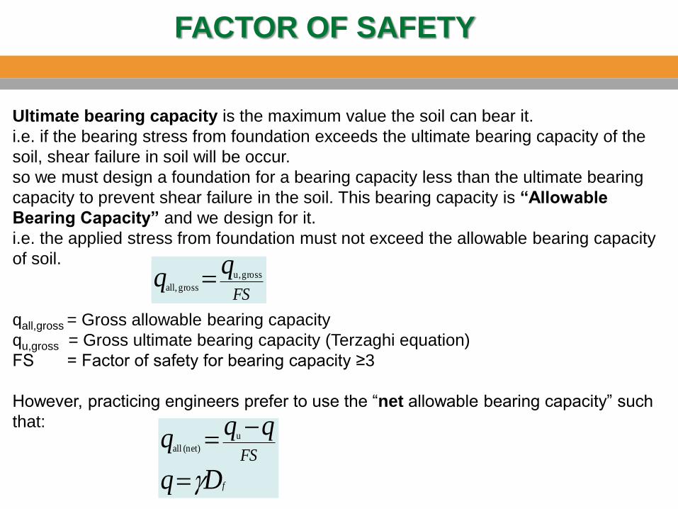
Ultimate bearing capacity is the maximum value the soil can bear it.
i.e. if the bearing stress from foundation exceeds the ultimate bearing capacity of the
soil, shear failure in soil will be occur.
so we must design a foundation for a bearing capacity less than the ultimate bearing
capacity to prevent shear failure in the soil. This bearing capacity is “Allowable
Bearing Capacity” and we design for it.
i.e. the applied stress from foundation must not exceed the allowable bearing capacity
of soil.
qall,gross = Gross allowable bearing capacity
qu,gross = Gross ultimate bearing capacity (Terzaghi equation)
FS = Factor of safety for bearing capacity ≥3
However, practicing engineers prefer to use the “net allowable bearing capacity” such
that:
FS
qq gross u,
gross all,
fDq
qqqFS
g
u
(net) all

Example 6.1

Example 6.2

Modification of Bearing Capacity Equations for Water Table
Terzaghi equation gives the ultimate bearing capacity based on the assumption
that the water table is located well below the foundation.
However, if the water table is close to the foundation, the bearing capacity will
decrease due to the effect of water table, so, some modification of the bearing
capacity equation will be necessary.
The values which will be modified are:
1. q (for soil above the foundation) in the second term of equation.
2. g (for the underlying soil) in the third term of equation .
There are three cases according to location of water table:
Case I. The water table is located so that 0≤D1≤Df
q = D1g+ D2(gsat− gw)
g → g ′= gsat− gw

Modification of Bearing Capacity Equations for Water Table
Case II. The water table is located so that 0≤d≤B :
Case III. The water table is located so that d≥B
in this case the water table is assumed have no effect on the ultimate
bearing capacity.

The General Bearing Capacity Equation
Terzagi’s equations shortcomings:
They don’t deal with rectangular foundations (0<B/L<1).
The equations do not take into account the shearing resistance along the
failure surface in soil above the bottom of the foundation.
The inclination of the load on the foundation is not considered (if exist).
To account for all these shortcomings, Meyerhof suggested the following
form of the general bearing capacity equation:
qu = c’ NcFcsFcdFci+ q NqFqsFqdFqi+ 0.5 B g NgFgs FgdFgiWhere
C’=Cohesion of the underlying soil
q = Effective stress at the level of the bottom of the foundation.
g = Unit weight of the underlying soil
B = Width of footing (=diameter for a circular foundation).
Nc, Nq, Ng = Bearing capacity factors (Table 4.2)
Fcs, Fqs, Fgs= Shape factors.
Fcd, Fqd, Fgd = Depth factors.
Fci, Fqi, Fgi = Inclination factors.
In the case of inclined loading on a foundation, the general equation provides
the vertical component.

Notes:
1. This equation is valid for both general and local shear failure.
2. This equation is similar to original equation for ultimate bearing capacity
(Terzaghi’s equation) which was derived for continuous foundation, but the
shape, depth, and load inclination factors are added to Terzaghi’s equation to
be suitable for any case may exist.
The General Bearing Capacity Equation
Bearing Capacity Factors: Nc, Nq, Ng
The angle α=ϕ’ (according Terzaghi theory) was replaced by α=45+ϕ’/2.
So, the bearing capacity factor will be changed.
The variations of bearing capacity factors (Nc, Nq, Ng ) and underlying soil
friction angle (ϕ’) are given in Table 4.2.

The General Bearing Capacity Equation
Table 6.2

The General Bearing Capacity Equation
Shape factors:
Notes:
1. If the foundation is continuous or strip →B/L=0.0
2. If the foundation is circular→B=L=diameter→B/L=1

The General Bearing Capacity Equation
Depth Factors:
Important Notes:
1. If the value of (B) or (Df)is required, you
should do the following:
Assume (Df/B≤1) and calculate depth factors in
term of (B) or (Df).
Substitute in the general equation, then
calculate (B) or (Df).
After calculating the required value, you must
check your assumption→(Df/B≤1).
If the assumption is true, the calculated value
is the final required value.
If the assumption is wrong, you must calculate
depth factors in case of (Df/B>1) and then
calculate (B) or (Df) to get the true value.
2. For both cases (Df/B≤1)and(Df/B>1)
if ϕ>0→ calculate Fqd firstly, because Fcd
depends on Fqd.

The General Bearing Capacity Equation
Inclination Factors:
Note:
If β°=ϕ→ Fgi =0.0, so you 𝐝𝐨𝐧′𝐭 𝐧𝐞𝐞𝐝 to calculate Fgs and Fgd, because
the last term in Meyerhof equation will be zero.

Example 6.3
575 kN/m

Read Examples 6.4 & 6.5

Ng Relationships
Table 6.5


EFFECT OF SOIL COMPRESSIBILITY
The change of failure mode is due to soil compressibility.
Vesic (1973) proposed the following modification to the
general bearing capacity equation:
qu = c’ NcFcsFcdFcc+ q NqFqsFqdFqc+ 0.5 B g NgFgs FgdFgc
where Fcc, Fqc, and Fgc are soil compressibility
factors.
Steps for calculating the soil compressibility
factors.
Page 232

EFFECT OF SOIL COMPRESSIBILITY
Table 6.8
Figure 6.17

EXAMPLE 6.6
Example 6.6

ECCENTRICALLY LOADED FOUNDATION
If the load applied on the foundation is in the center of the foundation
without eccentricity, the bearing capacity of the soil will be uniform at any
point under the foundation (as shown in figure) because there is no any
moments on the foundation, and the general equation for stress under the
foundation is:
In this case, the load is in the center of the foundation and there are no
moments so,
(uniform at any point below the foundation)A
Qq Stress
y
y
x
x StressI
xMI
yMQqA

ECCENTRICALLY LOADED FOUNDATION
However, in several cases, as with the base of a retaining wall or neighbor
footing, the loads does not exist in the center, so foundations are subjected to
moments in addition to the vertical load (as shown in the figure).
In such cases, the distribution of pressure by the foundation on the soil is not
uniform because there is a moment applied on the foundation and the stress
under the foundation will be calculated from:
ty)eccentrici way (two Stressy
y
x
x
IxM
IyM
AQq
tyeccentrici way one StressI
McAQq

ONE WAY ECCENTRICITY
tyeccentrici way one
StressI
McAQq
Since the pressure under the foundation is not
uniform, there are maximum and minimum pressures
(under the two edges of the foundation) and we
concerned about calculating these two pressures.
Assume the eccentricity is in direction of (B)
A=B×L
M=Q×e
c=B/2 (maximum distance from the center)
(I is about the axis that resists the moment)12
3
LB
I

ONE WAY ECCENTRICITY
There are three cases for calculating maximum and minimum pressures
according to the values of (e and B/6 )
Case I. (For 𝐞<𝐁/𝟔):
)61(*
*26**
*
12*32
***
Be
LBQq
LB
eQLB
Q
LB
BeQLB
)61(*
)61(*
min
max
Be
LBQq
Be
LBQq
If eccentricity in (L) direction (For e<L/6):
)61(*
)61(*
min
max
Le
LBQq
Le
LBQq
In this case, qmin is positive

ONE WAY ECCENTRICITY
Case II. (For 𝐞=𝐁/𝟔):
0 )11(*
)61(*
min
max
LBQq
Be
LBQq
If eccentricity in (L) direction (For e= L/6):
0 )11(*
)61(*
min
max
LBQq
Le
LBQq

ONE WAY ECCENTRICITY
Case III. (For 𝐞>𝐁/𝟔):
As shown in the figure, the value of (qmin)
is negative (i.e. tension in soil), but we
know that soil can’t resist any tension,
thus, negative pressure must be
prevented by making (qmin=0) at distance
(x) from point (A) as shown in the figure,
and determine the new value of (qmax) by
static equilibrium as following:
R=area of triangle*L
=0.5*qmax,new*X*L (1)
ΣFy=0.0 →R=Q (2)
ΣM@A=0.0 →Q*(B/2−e)=R*X/3
(but from Eq.2→R=Q)→X=3(B/2−e)
Substitute by X in Eq. (1) →
R=Q=0.5*qmax,new*3(B/2−e)*L
→qmax,new=4Q/[3L(B−2e)]

ONE WAY ECCENTRICITY
Case III. (For 𝐞>𝐁/𝟔):
If eccentricity in (L) direction
(For e> L/6):
qmax,new=4Q/[3B(L−2e)]
Note:
If the foundation is circular
Calculate qmax and qmin 64
4I
2c
4
2A
D
D
D
IMc
AQq

Ultimate Bearing Capacity under Eccentric
Loading One-Way Eccentricity
Effective Area Method:
If the load does not exist in the center of the foundation, or if the
foundation located to moment in addition to the vertical loads, the
stress distribution under the foundation is not uniform. So, to
calculate the ultimate (uniform) bearing capacity under the foundation,
new area should be determined to make the applied load in the center
of this area and to develop uniform pressure under this new area. This
new area is called Effective area.

Ultimate Bearing Capacity under Eccentric
Loading One-Way Eccentricity

Ultimate Bearing Capacity under Eccentric
Loading One-Way Eccentricity

EXAMPLE 6.7

Ultimate Bearing Capacity under Eccentric
Loading Two-Way Eccentricity
Figure 6.25
Figure 6.25

Ultimate Bearing Capacity under Eccentric
Loading Two-Way Eccentricity
Figure 6.26
Figure 6.26

Ultimate Bearing Capacity under Eccentric
Loading Two-Way Eccentricity
Figure 6.27
Figure 6.27

Ultimate Bearing Capacity under Eccentric
Loading Two-Way Eccentricity
Figure 6.28
Figure 6.28
Figure 6.28

Ultimate Bearing Capacity under Eccentric
Loading Two-Way Eccentricity
Figure 6.29
Figure 6.29

Ultimate Bearing Capacity under Eccentric
Loading Two-Way Eccentricity
Figure 6.30
Figure 6.30
6.10
Table 6.10

EXAMPLE 6.10

EXAMPLE 6.10

Read Examples 6.11 & 6.12

Bearing Capacity of a Continuous Foundation
Subjected to Eccentrically Inclined Loading
Partially Compensated Case
Meyerhof’s effective area method can be used to determine the ultimate load Qu(ei).
the vertical component of the soil reaction.

Bearing Capacity of a Continuous Foundation
Subjected to Eccentrically Inclined Loading
Patra et al. (2012a) proposed a reduction factor to estimate Qu(ei) for a foundation
on granular soil:
Reinforced Case (Granular Soil)
Patra et al. (2012b) conducted several model tests on continuous foundations on granular soil and
gave the following correlation to estimate Qu(ei)

EXAMPLE 6.13

Read Example 6.14

IMPORTANT NOTES
1. The soil above the bottom of the foundation are used only to calculate the
term (q) in the second term of bearing capacity equations (Terzaghi and
Meyerhof) and all other factors are calculated for the underlying soil.
2. Always the value of (q) is the effective stress at the level of the bottom of
the foundation.
3. For the underlying soil, if the value of (c=cohesion=0.0) you don’t have to
calculate factors in the first term in equations (Nc in Terzaghi’s equations)
and (Nc, Fcs, Fcd, Fci in Meyerhof equation).
4. For the underlying soil, if the value of (ϕ=0.0) you don’t have to calculate
factors in the last term in equations (Ng in Terzaghi’s equations) and
(Ng, Fgs,Fgd,Fgi in Meyerhof equation).
5. If the load applied on the foundation is inclined with an angle (β=ϕ). The
value of (Fgi) will be zero, so you don’t have to calculate factors in the last
term of Meyerhof equation (Ng, Fgs,Fgd).

IMPORTANT NOTES
6. Always if we want to calculate the eccentricity, it’s calculated as following:
7. If the foundation is square, strip or circular, you may calculate (qu) from
Terzaghi or Meyerhof equations (should be specified in the problem).
8. But, if the foundation is rectangular, you must calculate (qu) from Meyerhof
general equation.
9. If the foundation width (B) is required, and there exist water table below
the foundation at distance (d), you should assume d≤B, and calculate B, then
make a check for your assumption.
Loads Vertical
Moment Overalle
Related Documents