6.1 Chapter 6: Structural Analysis Chapter Objectives • To show how to determine the forces in the members of a truss using the method of joints and the method of sections. • To analyze the forces acting on the members of frames and machines composed of pin-connected members. In this chapter, we shall consider problems dealing with the equilibrium of structures made of several connected parts. • These problems call for the determination of the following forces. 1. External forces acting on the structure (reactions). 2. “Internal forces” – forces that hold together the various parts of the structure. Newton’s Third Law states, “The forces of action and reaction between bodies in contact have the same magnitude, same line of action, and opposite sense.” In this chapter, we shall consider three broad categories of engineering structures. 1. Trusses. • Trusses consist of straight members connected at joints located at the ends of the members. • Members of a truss are “two-force” members. 2. Frames. • Frames always contain at least one “multi-force member.” 3. Machines. • Machines are designed to transmit and modify forces, and are structures containing moving parts. • Machines, like frames, always contain at least one “multi-force member.” 6.1 Simple Truss A truss is one major type of engineering structures and is used in bridges and buildings. • A truss consists of straight members connected at joints. • Truss members are connected at their ends only. • No member is continuous through a joint.

Welcome message from author
This document is posted to help you gain knowledge. Please leave a comment to let me know what you think about it! Share it to your friends and learn new things together.
Transcript

6.1
Chapter 6: Structural Analysis
Chapter Objectives
• To show how to determine the forces in the members of a truss using the method
of joints and the method of sections.
• To analyze the forces acting on the members of frames and machines composed of
pin-connected members.
In this chapter, we shall consider problems dealing with the equilibrium of structures
made of several connected parts.
• These problems call for the determination of the following forces.
1. External forces acting on the structure (reactions).
2. “Internal forces” – forces that hold together the various parts of the
structure.
Newton’s Third Law states, “The forces of action and reaction between bodies in
contact have the same magnitude, same line of action, and opposite sense.”
In this chapter, we shall consider three broad categories of engineering structures.
1. Trusses.
• Trusses consist of straight members connected at joints located at the ends of
the members.
• Members of a truss are “two-force” members.
2. Frames.
• Frames always contain at least one “multi-force member.”
3. Machines.
• Machines are designed to transmit and modify forces, and are structures
containing moving parts.
• Machines, like frames, always contain at least one “multi-force member.”
6.1 Simple Truss
A truss is one major type of engineering structures and is used in bridges and
buildings.
• A truss consists of straight members connected at joints.
• Truss members are connected at their ends only.
• No member is continuous through a joint.

6.2
Truss Frame
The members of a truss are slender and can support little lateral load.
• All loads must be applied at the joints and not along the members themselves.
• In the case of bridge trusses, the dead
loads and traffic loads from the deck are
first carried by “stringers” which in turn
transmit the loads to “floor beams”, and
then the loads are finally transmitted to
the joints of the supporting side trusses
(ref. Fig. 6-2 in textbook).
Assumptions for Design
1. All loadings are applied at the joints.
2. The members are joined together by smooth pins.
Because of these two assumptions, each truss member acts as a two-force
member.
• The member is either in tension or compression.
Although the members are actually joined together by means of riveted, bolted, or
welded connections, the members are considered to be pinned together.
• The forces acting at each end of the member reduce to a single force and no
couple.
• Each member is treated as a two-force member.
Actual connection (Gusset Plate)
The moments that are created at
the ends of the members are small
and considered insignificant.

6.3
Simple Truss
The triangle ABC is considered the “basic truss.”
• The truss is said to be a “rigid truss” meaning
that the truss is stable and will not collapse.
• The only possible deformation involves small
changes in the length of its members.
A large truss may be obtained by successively adding two members, attaching them
to separate existing joints, and connecting them at a new joint.
• A truss constructed in this manner is called a “simple truss.”
• In a simple truss, the total number of members is related to the total number
of joints by the following equation.
m = 2 n – 3
where
n = the total number of joints
m = the total number of members
6.2 The Method of Joints
A truss may be considered as a group of pins and two-force members.
• We can dismember a truss and draw a free-body diagram for each pin.
• Since the entire truss is in equilibrium, each pin must be in equilibrium.
Consider the truss shown below.

6.4
Each pin represents a concurrent force system.
• At each pin we can write only two equations of equilibrium (a.k.a. equations of
statics).
∑ Fx = 0 and ∑ Fy = 0
In the case of a simple truss, the number of members and the number of pins
(joints) are related by the following equation.
m = 2 n – 3
where
n = the number of pins (joints)
m = number of members
and the number of unknowns that can be determined by the pins is
m + 3 (i.e. 2 n = m + 3).
• Thus, the forces in all the members plus the two components of the reaction at
A (i.e. Ax and Ay) and the vertical reaction at C (i.e. Cy) may be found using the
free-body diagrams of the pins.
• Typically, the entire truss is treated as a rigid body to determine the reactions
at the supports.
The “Method of Joints” solution is good if the entire truss is to be analyzed (i.e. all
the forces in each member is required).
• The solution must begin where there are only two unknown forces, usually at one
of the supports.
6.5
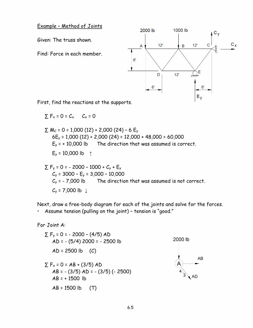
Example – Method of Joints
Given: The truss shown.
Find: Force in each member.
First, find the reactions at the supports.
∑ Fx = 0 = Cx Cx = 0
∑ MC = 0 = 1,000 (12) + 2,000 (24) – 6 Ey
6Ey = 1,000 (12) + 2,000 (24) = 12,000 + 48,000 = 60,000
Ey = + 10,000 lb The direction that was assumed is correct.
Ey = 10,000 lb ↑
∑ Fy = 0 = - 2000 – 1000 + Cy + Ey
Cy = 3000 – Ey = 3,000 – 10,000
Cy = - 7,000 lb The direction that was assumed is not correct.
Cy = 7,000 lb ↓
Next, draw a free-body diagram for each of the joints and solve for the forces.
• Assume tension (pulling on the joint) – tension is “good.”
For Joint A:
∑ Fy = 0 = - 2000 – (4/5) AD
AD = - (5/4) 2000 = - 2500 lb
AD = 2500 lb (C)
∑ Fx = 0 = AB + (3/5) AD
AB = - (3/5) AD = - (3/5) (- 2500)
AB = + 1500 lb
AB = 1500 lb (T)
6.6
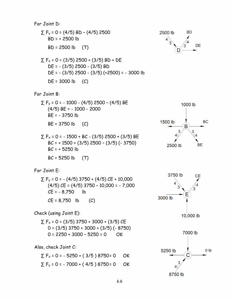
For Joint D:
∑ Fy = 0 = (4/5) BD – (4/5) 2500
BD = + 2500 lb
BD = 2500 lb (T)
∑ Fx = 0 = (3/5) 2500 + (3/5) BD + DE
DE = - (3/5) 2500 - (3/5) BD
DE = - (3/5) 2500 - (3/5) (+2500) = - 3000 lb
DE = 3000 lb (C)
For Joint B:
∑ Fy = 0 = - 1000 - (4/5) 2500 – (4/5) BE
(4/5) BE = - 1000 - 2000
BE = - 3750 lb
BE = 3750 lb (C)
∑ Fx = 0 = - 1500 + BC - (3/5) 2500 + (3/5) BE
BC = + 1500 + (3/5) 2500 – (3/5) (- 3750)
BC = + 5250 lb
BC = 5250 lb (T)
For Joint E:
∑ Fy = 0 = - (4/5) 3750 + (4/5) CE + 10,000
(4/5) CE = (4/5) 3750 – 10,000 = - 7,000
CE = - 8,750 lb
CE = 8,750 lb (C)
Check (using Joint E):
∑ Fx = 0 = (3/5) 3750 + 3000 + (3/5) CE
0 = (3/5) 3750 + 3000 + (3/5) (- 8750)
0 = 2250 + 3000 – 5250 = 0 OK
Also, check Joint C:
∑ Fx = 0 = - 5250 + ( 3/5 ) 8750 = 0 OK
∑ Fy = 0 = - 7000 + ( 4/5 ) 8750 = 0 OK
6.7
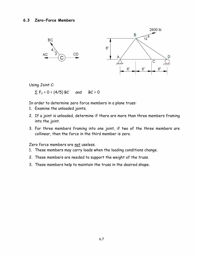
6.3 Zero-Force Members
Using Joint C:
∑ Fy = 0 = (4/5) BC and BC = 0
In order to determine zero force members in a plane truss:
1. Examine the unloaded joints.
2. If a joint is unloaded, determine if there are more than three members framing
into the joint.
3. For three members framing into one joint, if two of the three members are
collinear, then the force in the third member is zero.
Zero force members are not useless.
1. These members may carry loads when the loading conditions change.
2. These members are needed to support the weight of the truss.
3. These members help to maintain the truss in the desired shape.

6.8
6.4 The Method of Sections
If the force in only one member or if the forces in only a few members are
desired, the “Method of Sections” is a more efficient method of solution.
• In practice, the portion of the truss to be analyzed is obtained by “passing a
section” through three members of the truss, at least one of which is the
desired member.
• The “section” is a line that is drawn which divides the truss into two completely
separate parts, but does not intersect more than three members if possible.
• Then, if the entire truss is in equilibrium, then any portion of the truss is in
equilibrium also.
Consider the truss shown at the right.
• To find the internal forces in
members BD, BE, and CE, make a cut
through these members.
Assuming tension in these members:
Use ∑ ME = 0 to find BD.
Use ∑ Fy = 0 to find BE.
Use ∑ MB = 0 to find CE.
6.9
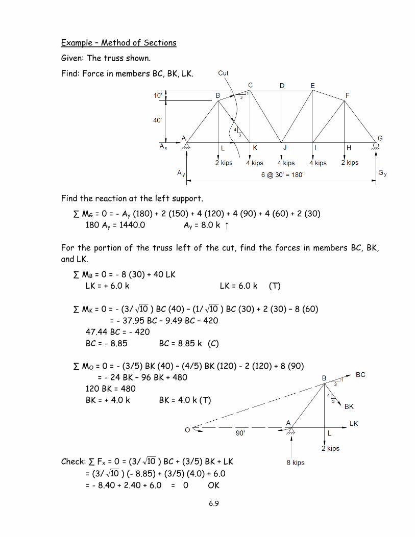
Example – Method of Sections
Given: The truss shown.
Find: Force in members BC, BK, LK.
Find the reaction at the left support.
∑ MG = 0 = - Ay (180) + 2 (150) + 4 (120) + 4 (90) + 4 (60) + 2 (30)
180 Ay = 1440.0 Ay = 8.0 k ↑
For the portion of the truss left of the cut, find the forces in members BC, BK,
and LK.
∑ MB = 0 = - 8 (30) + 40 LK
LK = + 6.0 k LK = 6.0 k (T)
∑ MK = 0 = - (3/ 10 ) BC (40) – (1/ 10 ) BC (30) + 2 (30) – 8 (60)
= - 37.95 BC – 9.49 BC – 420
47.44 BC = - 420
BC = - 8.85 BC = 8.85 k (C)
∑ MO = 0 = - (3/5) BK (40) – (4/5) BK (120) - 2 (120) + 8 (90)
= - 24 BK – 96 BK + 480
120 BK = 480
BK = + 4.0 k BK = 4.0 k (T)
Check: ∑ Fx = 0 = (3/ 10 ) BC + (3/5) BK + LK
= (3/ 10 ) (- 8.85) + (3/5) (4.0) + 6.0
= - 8.40 + 2.40 + 6.0 = 0 OK

6.10
Example – Method of Sections (K truss)
Given: The truss shown.
Find: Force in upper chord EJ, lower chord GH, and diagonals FJ & FH.
Find the reactions at the supports.
∑ MV = 0 = - 80 Ay + 8 (60) + 8 (50)
Ay = + 11.0 k
Ay = 11.0 k ↑ (as assumed)
Certain trusses will require more than a single cut.
• For the K-truss, a vertical cut crosses four members; thus, there are four
unknowns.
• But using a different cut, forces in a couple of the required members may be
found.
For Cut 1:
∑ MG = 0 = - 11 (20) – EJ (20)
EJ = - 11.0 k
EJ = 11.0 k (C)
∑ ME = 0 = GH (20) - 11 (20)
GH = + 11.0 k
GH = 11.0 k (T)
6.11
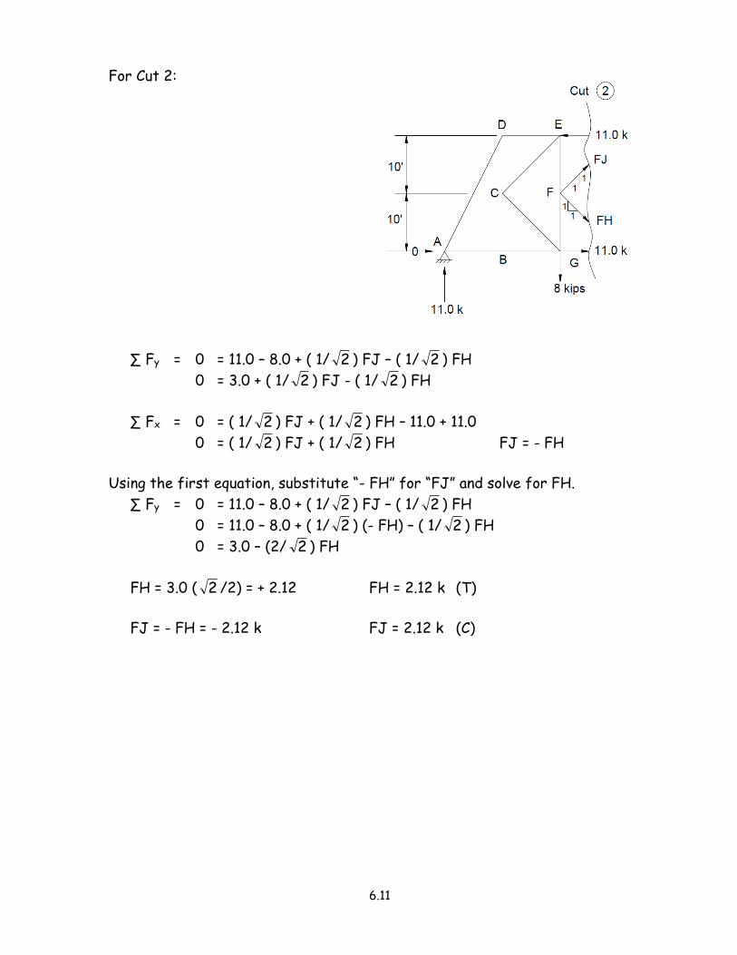
For Cut 2:
∑ Fy = 0 = 11.0 – 8.0 + ( 1/ 2 ) FJ – ( 1/ 2 ) FH
0 = 3.0 + ( 1/ 2 ) FJ - ( 1/ 2 ) FH
∑ Fx = 0 = ( 1/ 2 ) FJ + ( 1/ 2 ) FH – 11.0 + 11.0
0 = ( 1/ 2 ) FJ + ( 1/ 2 ) FH FJ = - FH
Using the first equation, substitute “- FH” for “FJ” and solve for FH.
∑ Fy = 0 = 11.0 – 8.0 + ( 1/ 2 ) FJ – ( 1/ 2 ) FH
0 = 11.0 – 8.0 + ( 1/ 2 ) (- FH) – ( 1/ 2 ) FH
0 = 3.0 – (2/ 2 ) FH
FH = 3.0 ( 2 /2) = + 2.12 FH = 2.12 k (T)
FJ = - FH = - 2.12 k FJ = 2.12 k (C)
6.12
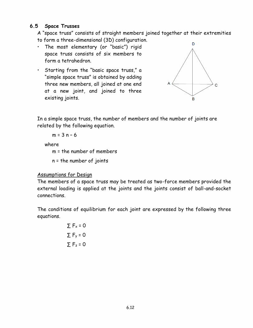
6.5 Space Trusses
A “space truss” consists of straight members joined together at their extremities
to form a three-dimensional (3D) configuration.
• The most elementary (or “basic”) rigid
space truss consists of six members to
form a tetrahedron.
• Starting from the “basic space truss,” a
“simple space truss” is obtained by adding
three new members, all joined at one end
at a new joint, and joined to three
existing joints.
In a simple space truss, the number of members and the number of joints are
related by the following equation.
m = 3 n – 6
where
m = the number of members
n = the number of joints
Assumptions for Design
The members of a space truss may be treated as two-force members provided the
external loading is applied at the joints and the joints consist of ball-and-socket
connections.
The conditions of equilibrium for each joint are expressed by the following three
equations.
∑ Fx = 0
∑ Fy = 0
∑ Fz = 0

6.13
6.6 Frames and Machines
A frame is a structure that contains at least one multi-force member; that is, a
member acted upon by three or more forces.
• Note the contrast to truss members that consist of all two-force members.
Analyzing a Frame
Consider the crane shown.
Using the three equations of equilibrium,
we can determine the tension T in the
cable, and the components of the
reaction at A.
∑ MA = 0 yields T
∑ Fx = 0 yields Ax
∑ Fy = 0 yields Ay
Free-Body Diagrams
In order to determine the internal forces holding the various parts of the frame
together, we must “dismember” the frame and draw a free-body diagram for each
part.
Points B, C, and E are pin connections and, therefore, are replaced by horizontal
and vertical restraining forces.
• As we assign directions to the components of the reactions, Newton’s third law
(equal and opposite forces) must be satisfied.

6.14
Check for determinacy.
• There are 3 equations for each free-body diagram.
• There are 4 free-body diagrams; thus, we can solve for as many as 12 unknowns.
In this problem there are only 9 unknowns.
• The two components for each of the forces at pins B, C, and E.
• The two components of the reaction at A.
• The tension in the cable.
Equations of Equilibrium
Using the equations of equilibrium, the solution follows as outlined below.
• Using the entire structure as a free-body diagram, solve for the components of
the reaction at A (that is, Ax and Ay) and the tension T in the cable.
• Then using a free-body diagram of member ABCD:
∑ MB = 0 yields Cx
∑ MC = 0 yields Bx
• Using a free-body diagram of member CEF:
∑ MC = 0 yields Ey
∑ ME = 0 yields Cy
• Using a free-body diagram of member BE:
∑ Fx = 0 yields Ex
∑ Fy = 0 yields By
Frames Which Cease to be Rigid When Detached from Their Supports
The reactions cannot be completely determined from the free-body diagram of the
entire frame.
• Thus, we must dismember the frame even to find the external forces.
• Equilibrium equations are said to be “necessary, but not sufficient” for a non-
rigid structure.

6.15
Example – Frame Analysis
Given: Frame shown.
Find: Components of the forces acting
on each member of the frame.
Find the reactions at the supports.
∑ MA = 0 = - 360 (15) – 240 (33) + 12 Ex
12 Ex = 5400 + 7920 = 13,320 Ex = 1110 lb →
∑ Fx = 0 = Ax + Ex
Ax = - Ex = - 1110 lb Ax = 1110 lb ←
∑ Fy = 0 = Ay – 360 - 240
Ay = + 600 Ay = 600 lb ↑
Find the components of the forces acting on each member.
FBD 1
∑ MB = 0 = - 600 (6) + 18 Dy
18 Dy = + 3600
Dy = + 200
Dy = 200 lb ↑ on ABD
∑ MD = 0 = - 600 (24) - 18 By
18 By = - 14,400
By = - 800
By = 800 lb ↓ on ABD

6.16
FBD 2
∑ MC = 0 = - 12 Bx + 18 By + 360 (9) – 240 (9)
12 Bx = 18 (- 800) + 360 (9) – 240 (9)
= - 14,400 + 3240 – 2160 = - 13,320
Bx = - 1110 Bx = 1110 lb ← on ABD
∑ Fx = 0 = - Bx + Cx
Cx = Bx = - 1110 Cx = 1110 lb ← on BC
∑ Fy = 0 = - By – 360 + Cy - 240
Cy = By + 360 + 240
= - 800 + 360 + 240 = - 200 Cy = 200 lb ↓ on BC
FBD 3
∑ MC = 0 = 1110 (24) – 12 Dx Dx = 2220 lb ← on CDE

6.17
Machines
Machines are structures designed to transmit or modify forces.
• The solution involving forces on a machine is similar to that for a frame.
• The solution will generally involve the use of one or more free-body diagrams.
• The free-body diagrams should be chosen to include the input forces and the
reactions to the input forces.
Related Documents