Chapter 6 State Estimation Part 3 6.3 Inertial Navigation Systems Mobile Robotics - Prof Alonzo Kelly, CMU RI 1

Welcome message from author
This document is posted to help you gain knowledge. Please leave a comment to let me know what you think about it! Share it to your friends and learn new things together.
Transcript

Chapter 6 State Estimation
Part 3 6.3 Inertial Navigation Systems
Mobile Robotics - Prof Alonzo Kelly, CMU RI 1

Outline • 6.3 Sensors for State Estimation
– 6.3.1 Introduction – 6.3.2 Mathematics of Inertial Navigation – 6.3.3 Errors and Aiding in Inertial Navigation – 6.3.4 Example: Simple Odometry Aided AHRS – Summary
Mobile Robotics - Prof Alonzo Kelly, CMU RI 2

Outline • 6.3 Sensors for State Estimation
– 6.3.1 Introduction – 6.3.2 Mathematics of Inertial Navigation – 6.3.3 Errors and Aiding in Inertial Navigation – 6.3.4 Example: Simple Odometry Aided AHRS – Summary
Mobile Robotics - Prof Alonzo Kelly, CMU RI 3

History • Historical roots in German
Peenemunde Group. • Modern form credited to Charles
Draper et al. @MIT. • 1940s Germany:
– V2 program, gyroscopic guidance • 1950s Draper Labs, MIT:
– Shuler tuned INS – Floated rate integrating gyros (0.01
deg/hr) • 1960s DTGs
– not floated or temp compensated • 1970s RLGs, USA • 1980s Strapdown INS • 1990s GPS
Mobile Robotics - Prof Alonzo Kelly, CMU RI 4
V2
RLG Experiment

Introduction • Advantages
– Most accurate dead reckoning available. – Useful in wide excursion (outdoor) missions. – Work anywhere where gravity is known. – Are jamproof - require no external information. – Radiate nothing - exhibit perfect stealth.
• Disadvantages – Cannot sense accelerations of unpowered space flight. – Most errors exhibit Schuler oscillation (advantage?). – Most errors are time dependent. – Requires input of initial conditions.
Mobile Robotics - Prof Alonzo Kelly, CMU RI 5

Outline • 6.3 Sensors for State Estimation
– 6.3.1 Introduction – 6.3.2 Mathematics of Inertial Navigation – 6.3.3 Errors and Aiding in Inertial Navigation – 6.3.4 Example: Simple Odometry Aided AHRS – Summary
Mobile Robotics - Prof Alonzo Kelly, CMU RI 6

6.3.2 Mathematics of Inertial Navigation (Concept)
• Use Inertial Properties of Matter – Accelerometers – Gyros
• Do “Dead Reckoning” – Integrate acceleration twice
Mobile Robotics - Prof Alonzo Kelly, CMU RI 7
IMU
Computation

6.3.2 Mathematics of Inertial Navigation (Naïve Concept)
• Just integrating 3 accels will not work for a lot of reasons: – Accelerometers measure wrong
quantity. – They measure it in wrong
reference frame. – They represent it in wrong
coordinate system.
• The quest for ever better engineering solutions to these problems is the primary reason for the complexity of the modern INS.
Mobile Robotics - Prof Alonzo Kelly, CMU RI 8
accelerometers

6.3.2 Problem 1: Equivalence • Accelerometers don’t measure acceleration. • Specific force is: • Fix: must know gravity, then:
Mobile Robotics - Prof Alonzo Kelly, CMU RI 9
a = 9.8 m/s2
Weight on Earth
Freefall (Space)
At Rest (Earth)
Both Accelerating
T T

Problem 2: Inertial Frame of Reference • Now have inertial
acceleration. – Want earth-referenced
acceleration.
• Fix: account for earth angular velocity: – “Apparent forces”. – “gravity”, not gravitation
Mobile Robotics - Prof Alonzo Kelly, CMU RI 10
North Pole
1700 km/hr
centripetal
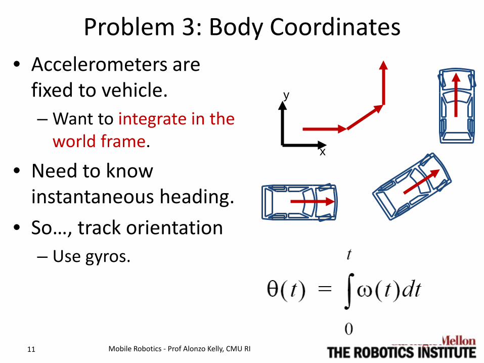
Problem 3: Body Coordinates • Accelerometers are
fixed to vehicle. – Want to integrate in the
world frame.
• Need to know instantaneous heading.
• So…, track orientation – Use gyros.
Mobile Robotics - Prof Alonzo Kelly, CMU RI 11
x
y
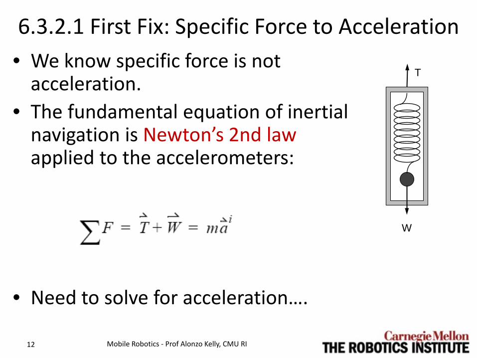
6.3.2.1 First Fix: Specific Force to Acceleration • We know specific force is not
acceleration. • The fundamental equation of inertial
navigation is Newton’s 2nd law applied to the accelerometers:
• Need to solve for acceleration….
Mobile Robotics - Prof Alonzo Kelly, CMU RI 12
T
W
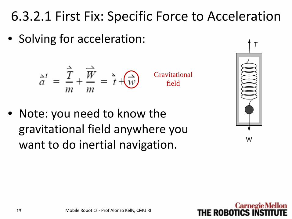
6.3.2.1 First Fix: Specific Force to Acceleration • Solving for acceleration:
• Note: you need to know the gravitational field anywhere you want to do inertial navigation.
Mobile Robotics - Prof Alonzo Kelly, CMU RI 13
Gravitational field
T
W

6.3.2.2 Second Fix: Remove Apparent Forces • Moving vehicle is a
moving reference frame. – Hence, sensors on-
board will sense apparent forces.
– Remove them with Coriolis law.
Mobile Robotics - Prof Alonzo Kelly, CMU RI 14
North Pole
1700 km/hr

6.3.2.2 Second Fix: Remove Apparent Forces
• Define Frames: – i: “inertial”, geocentric
nonrotating. – e: “earth”, geocentric, rotating. – v: “vehicle”, fixed to accels.
Also known as body frame.
Mobile Robotics - Prof Alonzo Kelly, CMU RI 15
zi
xi
yi
xe ye
ze
xv
yv
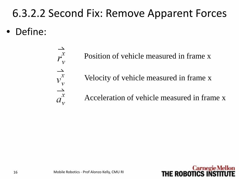
6.3.2.2 Second Fix: Remove Apparent Forces • Define:
Mobile Robotics - Prof Alonzo Kelly, CMU RI 16
Position of vehicle measured in frame x
Velocity of vehicle measured in frame x
Acceleration of vehicle measured in frame x

6.3.2.2 Second Fix: Remove Apparent Forces • Basic acceleration transformation under negligible
angular acceleration: • Let “o” = v, “m” = e, and “f” = i:
• The i and e origins are coincident. Hence:
Mobile Robotics - Prof Alonzo Kelly, CMU RI 17
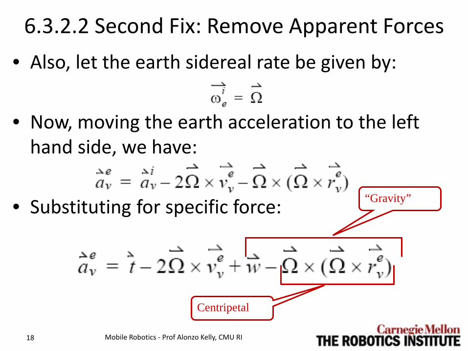
6.3.2.2 Second Fix: Remove Apparent Forces • Also, let the earth sidereal rate be given by:
• Now, moving the earth acceleration to the left
hand side, we have:
• Substituting for specific force:
Mobile Robotics - Prof Alonzo Kelly, CMU RI 18
“Gravity”
Centripetal

• The quantity: • Is known as “gravity” and denoted • Finally, we have “the” equation of inertial
navigation.
6.3.2.2 Second Fix: Remove Apparent Forces
Mobile Robotics - Prof Alonzo Kelly, CMU RI 19
This is the derivative of the velocity relative to e as computed by an earth-fixed observer.
Specific Force
Coriolis Gravity

6.3.2.2 Second Fix: Remove Apparent Forces • The computed solution in coordinate system
independent form is:
• These are only valid if you integrate in the earth frame (i.e. in earth-fixed coordinates).
Mobile Robotics - Prof Alonzo Kelly, CMU RI 20
You need to know: • a model of gravity • earth sidereal rate • specific forces • initial position • initial velocity • (gyros don’t appear in vector form)

6.3.2.2.1 Vector Formulation
Mobile Robotics - Prof Alonzo Kelly, CMU RI 22
+ +
from accels
+
-
+ -
_×Ω×Ω
_2 ×Ω
evv)( 0tv e
v )( 0tr e
v e
vr
3(_))(
eGM−
t
centrifugal Coriolis gravitation
∫tdt
0 ∫tdt
0

6.3.2.2 Gravity and Gravitation • Gravity is the force per unit mass
required to fix an object wrt the Earth. It includes centrifugal force.
• Gravitation is the force described in Newton’s law of gravitation.
• Only at the equator and at the poles does gravity point toward the center of the earth.
Mobile Robotics - Prof Alonzo Kelly, CMU RI 23
equator
circle of constant latitude
Ω
evr
×Ω×Ω−
G
g

6.3.2.3 Third Fix: Adopt a Coordinate System • The heart of the INS is the inertial measurement
unit (IMU) containing 3 accelerometers and 3 gyros.
• The gyros are used to track the orientation of the vehicle wrt the earth.
• You need orientation because: – and are known in earth coordinates, whereas…. – and are measured in body coordinates in a
modern strapdown system. • Can’t add em up unless they are in the same
coordinate system.
Mobile Robotics - Prof Alonzo Kelly, CMU RI 24
gt
Ωω
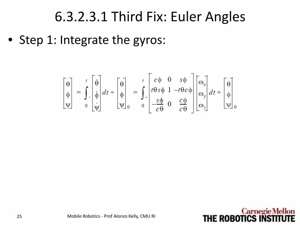
6.3.2.3.1 Third Fix: Euler Angles • Step 1: Integrate the gyros:
Mobile Robotics - Prof Alonzo Kelly, CMU RI 25

6.3.2.3.2 Third Fix: Direction Cosines • Step 1: Or, use direction cosine form (better):
Mobile Robotics - Prof Alonzo Kelly, CMU RI 26

6.3.2.3.3 Third Fix: Quaternions • Step 1: Or, use the quaternion form (best):
Mobile Robotics - Prof Alonzo Kelly, CMU RI 27

6.3.2.3.4 Third Fix: Earth Rate Compensation • When orientation aiding is
rare (yaw aiding is typically rare), it may be useful to remove earth rate from the gyros:
• .. Or its projection onto the yaw axis will be integrated. – Where is this projection
greatest?
Mobile Robotics - Prof Alonzo Kelly, CMU RI 28
equator
circle of constant latitude
Ω λsinΩ
λ
Ω
λλcosΩ
Note: n = e here

6.3.2.3 Third Fix: Adopt a Coordinate System • Step 2: Integrate the accels:
• Step 3: Integrate the velocity:
Mobile Robotics - Prof Alonzo Kelly, CMU RI 29
Outline • 6.3 Sensors for State Estimation
– 6.3.1 Introduction – 6.3.2 Mathematics of Inertial Navigation – 6.3.3 Errors and Aiding in Inertial Navigation – 6.3.4 Example: Simple Odometry Aided AHRS – Summary
Mobile Robotics - Prof Alonzo Kelly, CMU RI 30

6.3.3.1 Sensitivity
• Acceleration is multiplied by the square of time. – 1 hour2 = 13 million secs2.
• After 1 hour, the Coriolis (smallest) term accounts for over 9.5 Km of error.
Mobile Robotics - Prof Alonzo Kelly, CMU RI 31
For a vehicle at the equator, moving eastward at a velocity of 10 meters per second, and accelerating at 0.1 g

Error Explosion • For a 10 m/s vehicle at
the equator, the Coriolis term is tiny: – 1.5x10⁻⁴ g
• Consider an error of this magnitude…
• In one hour: – t2 = (3600)2 = 13 million
!! • Position Error:
– 9.5 Kilometers!!!
Mobile Robotics - Prof Alonzo Kelly, CMU RI 32

Error Dynamics: Gravity Feedback
• Consider predictions of gravity direction based on position. • This is called a Shuler loop.
Mobile Robotics - Prof Alonzo Kelly, CMU RI 33
Step 2: Spring is Deflected this way.
Step 1: Orientation error, (system thinks it is level).
Step 3: Interpret as Motion this way.
Step 4: Which rotates gravity prediction until more motion is unnecessary

Here
Mobile Robotics - Prof Alonzo Kelly, CMU RI 34
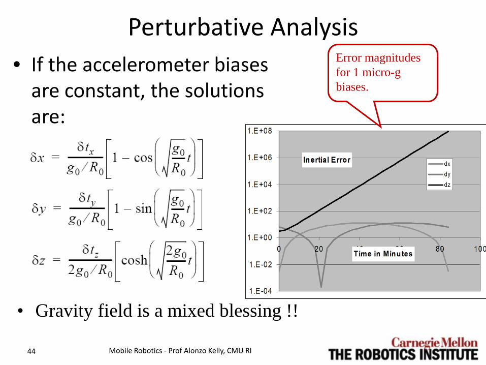
Perturbative Analysis • If the accelerometer biases
are constant, the solutions are:
Mobile Robotics - Prof Alonzo Kelly, CMU RI 44
Error magnitudes for 1 micro-g biases.
• Gravity field is a mixed blessing !!

6.3.3.2 Aided Inertial Mode
• Used on mobile robots: – Zero velocity update – Odometry – GPS – Landmarks / Map
matching – Magnetic heading
• Used more generally: – Barometric altitude – Radar altimeters – Doppler radar velocity
Mobile Robotics - Prof Alonzo Kelly, CMU RI 45
Note: Net effect of velocity aiding is to convert error dynamics from that of free Inertial to that of odometry.

6.3.3.3 Initialization • In self alignment, the INS is left stationary and:
– Accels determine direction of gravity in process called levelling.
– Gyros determine direction of earth’s spin vector in a process called gyrocompassing.
• Latitude can also be estimated in this way but not longitude.
• Modern GPS aided systems do “moving base alignment” where the difference in GPS readings over time can be used to determine vehicle heading.
Mobile Robotics - Prof Alonzo Kelly, CMU RI 46

Initialization • Need to measure two
non-collinear vectors. • Earth conveniently has
two: – Gravity - easy – Earth spin – takes time,
several minutes – Angle between them
gives latitude. • Gives orientation wrt
earth and latitude.
Mobile Robotics - Prof Alonzo Kelly, CMU RI 47
North Pole

Smiths Industries INS • Without GPS
– Static Heading: <0.1 deg. rms – Position: <0.35% DT
Horizontal – Altitude: <0.25% DT Vertical
• With GPS – Dynamic Heading: <0.1 deg.
rms – Position: <10 meters CEP – Altitude Accuracy: <10
meters VEP • Pitch and Roll Outputs: <0.05
deg. rms
Mobile Robotics - Prof Alonzo Kelly, CMU RI 49
• Initialization Time – Static: 3-5 minutes (gyrocompassing)
• Initialization Time – On-the-Move: 1-3 minutes

Watson Industries AHRS E304 • Attitude:
– 0.25% static, 2% dynamic • Heading:
– 1% static, 2% dynamic • Angular Rate:
– Scale factor 1% – Bias 0.02 deg/sec. – Bandwidth 25 Hz
• Acceleration: – Scale factor 1% – Bias 5 mg – Bandwidth 20 Hz
Mobile Robotics - Prof Alonzo Kelly, CMU RI 50

Accuracy • Commercial cruise systems
– Position: 0.2 nautical miles of error per hour of operation.
• In some cases, position accuracy along the trajectory (alongtrack) and both normal directions (crosstrack and vertical) are distinguished.
– Attitude (pitch and roll) : often accurate to 0.05°. – Heading: often accurate to 0.5°.
• Land vehicle navigation systems: – Position: 0.2% to 2% of distance traveled. – Attitude: 0.1° – Heading to 0.5°.
Mobile Robotics - Prof Alonzo Kelly, CMU RI 51
1 nm = 1852 meters = 6078 ft = 1 arc minute on earths surface

Outline • 6.3 Sensors for State Estimation
– 6.3.1 Introduction – 6.3.2 Mathematics of Inertial Navigation – 6.3.3 Errors and Aiding in Inertial Navigation – 6.3.4 Example: Simple Odometry Aided AHRS – Summary
Mobile Robotics - Prof Alonzo Kelly, CMU RI 52

6.3.4 Simple Odometry Aided AHRS • The AHRS is a degenerate form of inertial
navigation system, using much of the same components: – indicates orientation only.
• Device uses a strapped down IMU today. – Accels indicate gravity and acceleration – Gyros indicate angular velocity
• Distinguishing acceleration from gravity is still an issue - but less so.
Mobile Robotics - Prof Alonzo Kelly, CMU RI 53
Means not stabilized

6.4.3.1 Nav Eqns in Body Frame • Recall the inertial nav equation (Eq 6.46): • Lets express this in the body frame so that it
becomes unnecessary to known orientation. • Use the Coriolis theorem:
Mobile Robotics - Prof Alonzo Kelly, CMU RI 54
This adds another Apparent Coriolis Force.
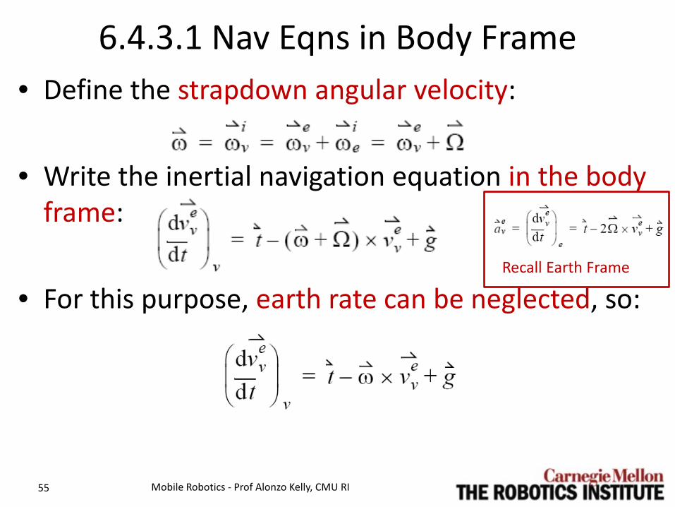
6.4.3.1 Nav Eqns in Body Frame • Define the strapdown angular velocity:
• Write the inertial navigation equation in the body
frame:
• For this purpose, earth rate can be neglected, so:
Mobile Robotics - Prof Alonzo Kelly, CMU RI 55
Recall Earth Frame

6.4.3.1 Nav Eqns in Body Frame • Solve for gravity:
• Everything on right is known from measurements. g on left is known in world coordinates.
Mobile Robotics - Prof Alonzo Kelly, CMU RI 56
This vanishes on an Ackerman vehicle during periods of constant speed. Otherwise, differentiate numerically.
Simply remove Coriolis term from the accel readings.

6.4.3.1 Nav Eqns in Body Frame • Write this in body coordinates:
• Can solve this for attitude (not yaw) in the rotation matrix using inverse kinematics. – Rotation around g is not observable.
Mobile Robotics - Prof Alonzo Kelly, CMU RI 57

6.4.3.2 Solving for Attitude • To get the attitude, express in body frame:
• Where:
• The transpose converts from world to body, thus:
Mobile Robotics - Prof Alonzo Kelly, CMU RI 58
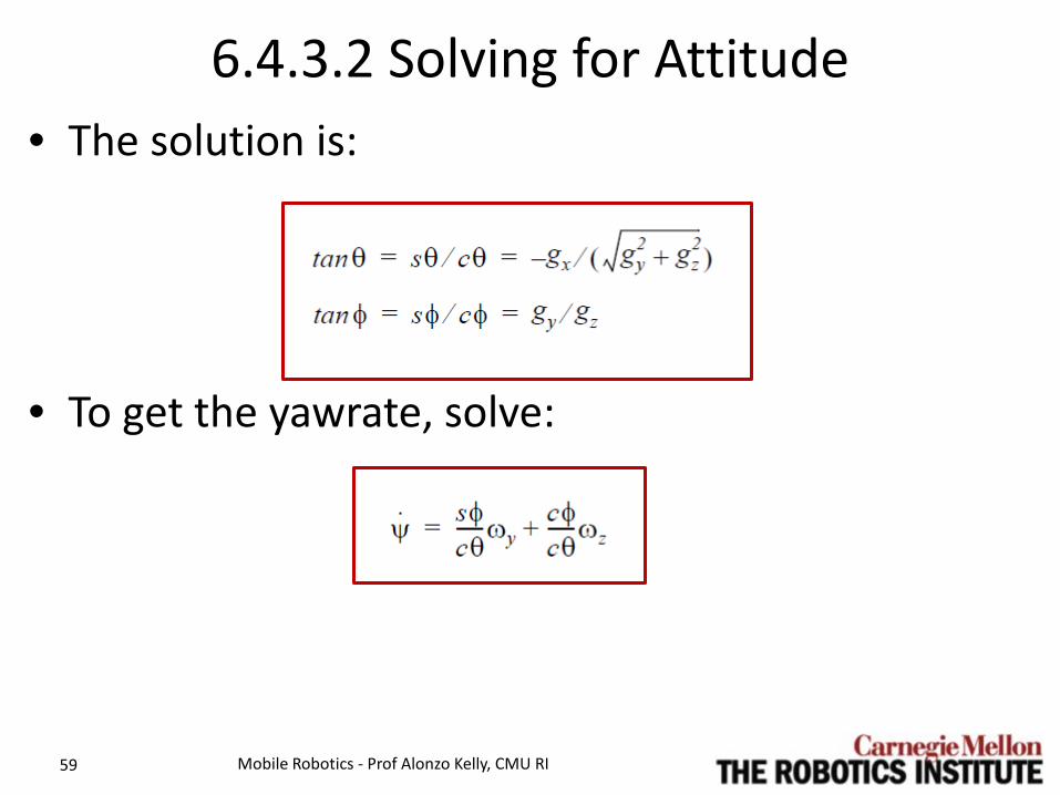
6.4.3.2 Solving for Attitude • The solution is:
• To get the yawrate, solve:
Mobile Robotics - Prof Alonzo Kelly, CMU RI 59

Outline • 6.3 Sensors for State Estimation
– 6.3.1 Introduction – 6.3.2 Mathematics of Inertial Navigation – 6.3.3 Errors and Aiding in Inertial Navigation – 6.3.4 Example: Simple Odometry Aided AHRS – Summary
Mobile Robotics - Prof Alonzo Kelly, CMU RI 60
Summary • Black magic ? • Hard to do well.
– Costs big bucks.
• Most accurate dead reckoning available. – Cruise: 0.2 nautical miles of error per hour of
operation.
• Indispensable on outdoor mobile robots. • Complementary technology to GPS.
Mobile Robotics - Prof Alonzo Kelly, CMU RI 61

Summary • Inertial navigation is based on Newton’s laws
– Works everywhere that gravity is known. – It is stealthy and jamproof.
• Modern “strapdown” systems – “computationally stabilized”. – no stabilized platform
• Naive approaches are seriously flawed. Must compensate for – Gravity – inertial forces – body fixed coordinates.
Mobile Robotics - Prof Alonzo Kelly, CMU RI 62
Summary • Free inertial performs miserably…
– 1 part in 10,000 acceleration error causes kilometers of position error after 1 hour of operation.
• Interesting Error Dynamics – Horizontal errors bounded, oscillate every 84 minutes – Vertical position is unstable without damping devices
• An AHRS unit can find attitude from accelerometers and gyros and odometry.
Mobile Robotics - Prof Alonzo Kelly, CMU RI 63
Related Documents