Chapter 6 Microlevel of H1 and V1

Chapter 6 Microlevel of H1 and V1. We start with some concepts from Chapter 5 that are essential for this chapter.
Dec 19, 2015
Welcome message from author
This document is posted to help you gain knowledge. Please leave a comment to let me know what you think about it! Share it to your friends and learn new things together.
Transcript

Chapter 6
Microlevel of H1 and V1

We start with some concepts from Chapter 5 that are essential
for this chapter.


ALU functions


Data In is not edge triggered by LD
Incrementation is edge triggered by INC

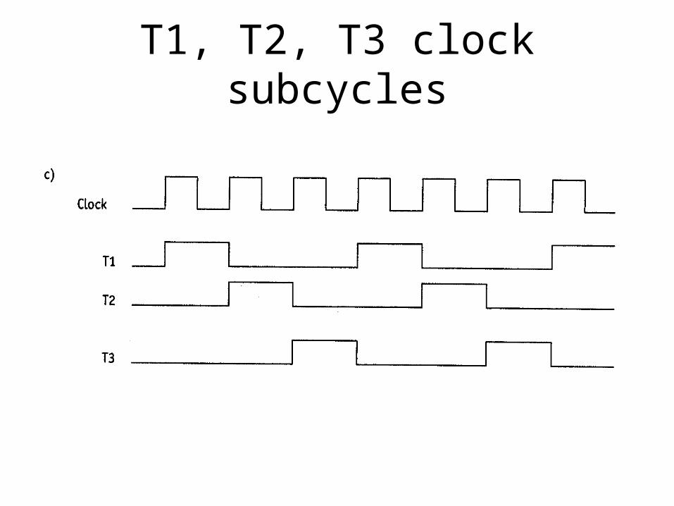
T1, T2, T3 clock subcycles

Components of H1
• Central Processing Unit (CPU)
• Clock/sequencer
• Main memory
• Keyboard
• Monitor

Two sections in the CPU
• Computational section: adds, subtracts, etc.
• Control section: generates signals that control the various circuits in the computer.

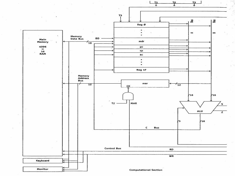
Computational section
• Consists of register bank, ALU, and interconnecting buses.
• Forms a circle: registers drive A and B buses; A and B buses drive ALU; ALU output drives registers.
• This circle is called the data path.


To increment the pc register
• Route the number 1 and the contents of the pc register to the ALU.
• Instruct the ALU to add.
• Route the output of the ALU back into the pc register.

The computer has many control inputs. For example, the ALU has three control inputs that determine its operation.

Executing a microinstruction
• Load the mir with a microinstruction from microstore.
• The outputs of the mir then drive the various control inputs in the computer.
• One or more micro-operations occur.

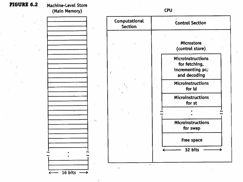
Main memory is external to the CPUMicrostore is internal to the CPU

Buses
• Memory data bus: bidirectional bus between CPU and main memory. RD determines its direction.
• Memory address bus: unidirectional bus from CPU to main memory.
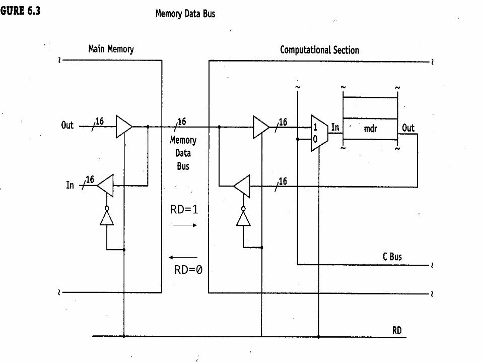
RD=0
RD=1

The mar is loaded from the B bus.
The mar holds an address so it is only 12 bits wide.

Output enabled
Control input
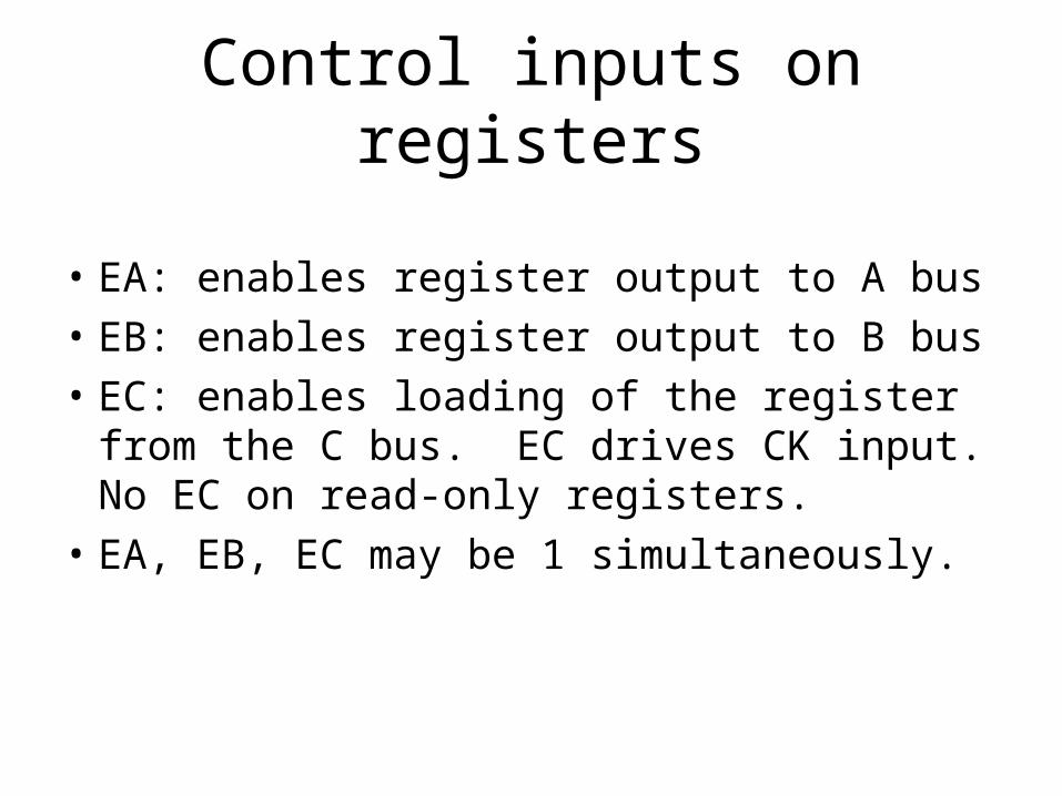
Control inputs on registers
• EA: enables register output to A bus
• EB: enables register output to B bus
• EC: enables loading of the register from the C bus. EC drives CK input. No EC on read-only registers.
• EA, EB, EC may be 1 simultaneously.

EA, EB, EC for register 6 are called EA6, EB6, and EC6
Naming control inputs on registers
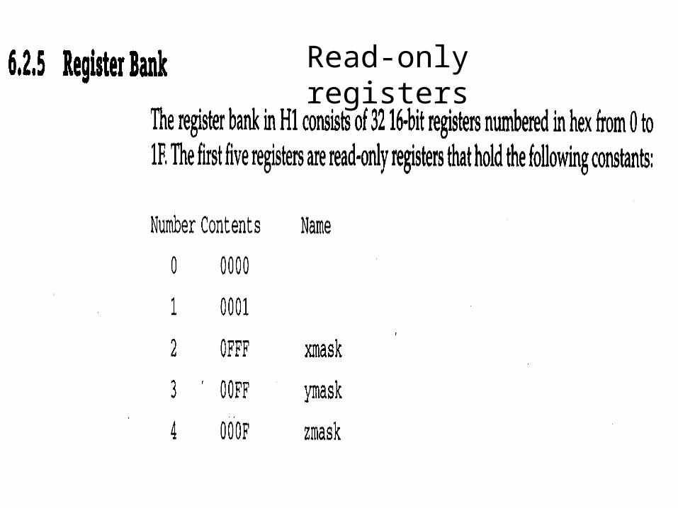
Read-only registers

Read-only register

Read/write registers

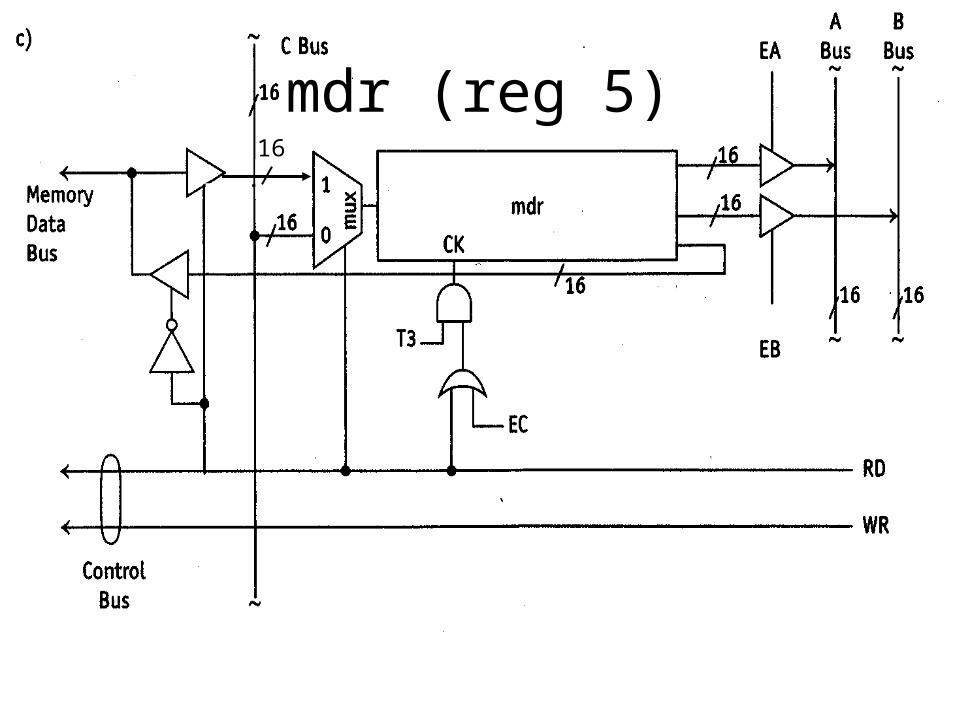
memory data register (mdr) (register 5)
• More complicated than other read/write registers.
• Can be loaded from either the C bus (if RD = 0 and EC = 1) or the memory data bus (if RD = 1).
• the mdr drives the memory data bus on a memory write operation.
mdr (reg 5)16

Control inputs needed to add 1 to the pc register (reg 6)
00110 00001 00110 100 0 0 0 000 xxxxxxxx
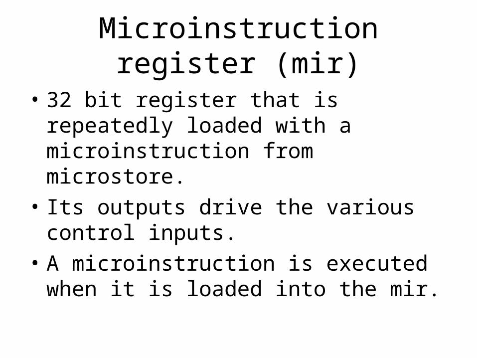
Microinstruction register (mir)
• 32 bit register that is repeatedly loaded with a microinstruction from microstore.
• Its outputs drive the various control inputs.
• A microinstruction is executed when it is loaded into the mir.

Reducing the size of a microinstruction and the mir
• We havea total of 97 control lines
• Use decoders to reduce number of inputs.
• A five-input decoder has 32 output lines– saves 32-5 = 27 bits in the microinstruction. See next slide.


Microinstruction program counter (mpc)
• At T1, the microinstruction whose address is in the mpc is loaded into the mir. This microinstruction is then “executed” at T2 and T3.
• At T2, the mpc is incremented. Thus, on the next T1, the next microinstruction is loaded into the mir and executed.


Transferring control
• We call a transfer of control at the machine level a jump.
• We call a transfer of control at the microlevel a branch.
• A jump is caused by loading a new address into the pc register.
• A branch is caused by loading a new address into the mpc register.

Branching
• Every microinstruction has an ADDR field—a field that can contain a branch-to address.
• To branch, the address in ADDR of the microinstruction in the mir is loaded into the mpc at T3.
• The mpc is loaded only if the branch multiplexer outputs a 1.


Reading/writing to main memory
• Reading and writing both require a two-microinstruction sequence.
• The first microinstruction loads the mar, and in the case of a write, the mdr.
• The second microinstruction triggers the read or write main memory operation by asserting RD or WR.
• The address on the memory address bus must be stable before RD or WR is asserted (which is why a two-microinstruction sequence is needed).
• The data on the memory data bus must be valid before WR is asserted.
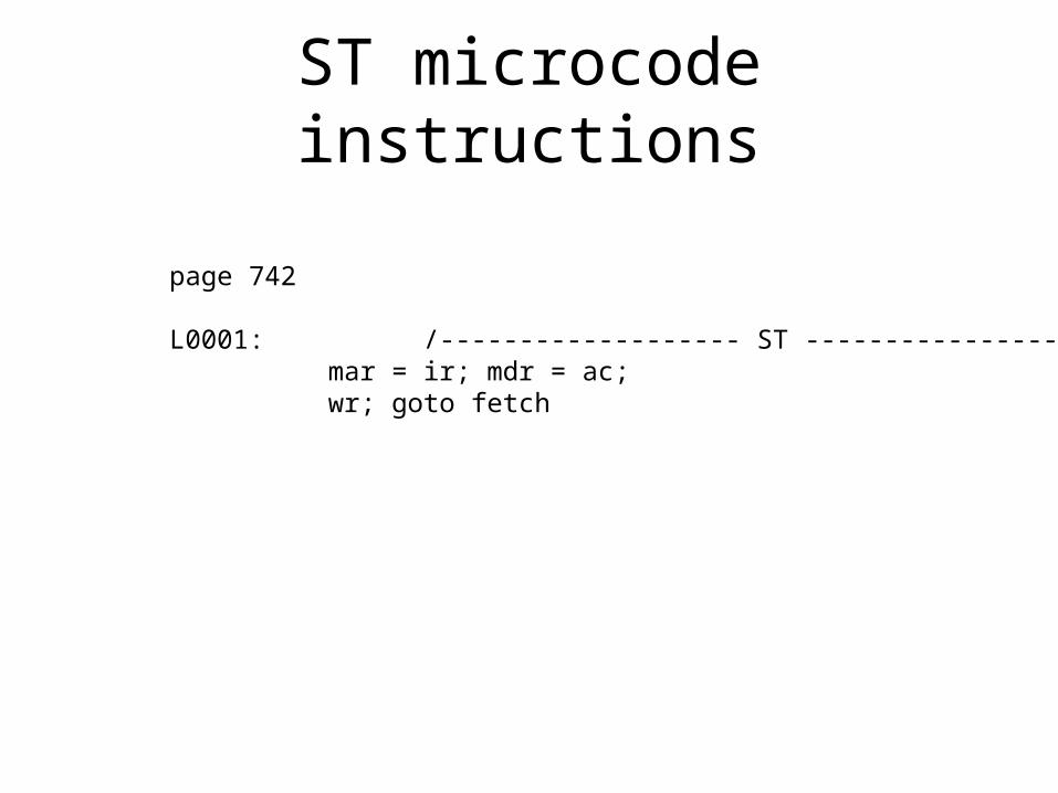
ST microcode instructions
page 742
L0001: /------------------- ST ----------------------------mar = ir; mdr = ac;wr; goto fetch

Timing—main memory write

Timing—main memory read


Basic instruction set
• A very simple instruction set (only 8 instructions)
• Its implementation in microcode is easy to understand.
• You will learn how to write microcode by studying the microcode for the basic instruction set. You will then be able to create new instruction sets by writing the microcode that implements them.

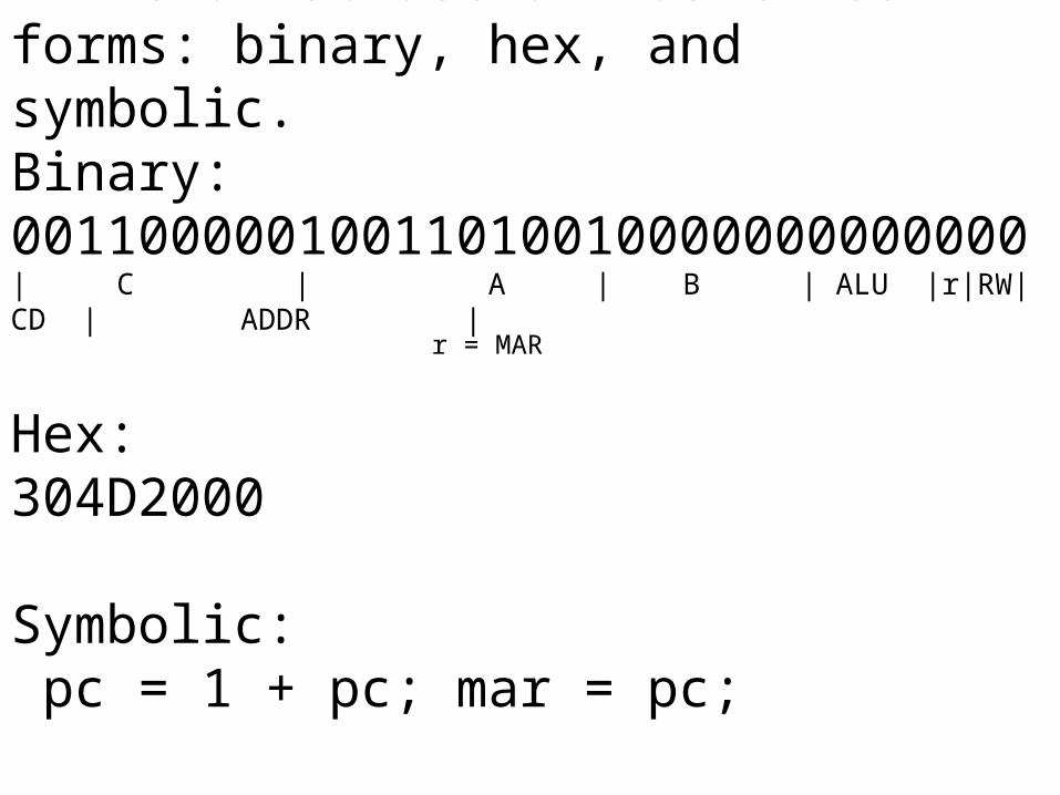
A microinstruction has three forms: binary, hex, and symbolic. Binary:00110000010011010010000000000000| C | A | B | ALU |r|RW|CD | ADDR |
Hex:304D2000
Symbolic: pc = 1 + pc; mar = pc;
r = MAR

What microcode that implements an instruction set must do

Instruction register (ir)
When the CPU fetches a machine instruction it places it in the ir.

Decoding register (dc)
The CPU also places a copy of the machine instruction in the dc register. The dc register is used
during instruction decoding.

The dc register holds the machine instruction as the instruction is shifted left in the decoding process. This shifting process corrupts the machine instruction in the dc register. However, the uncorrupted original is available in the ir.

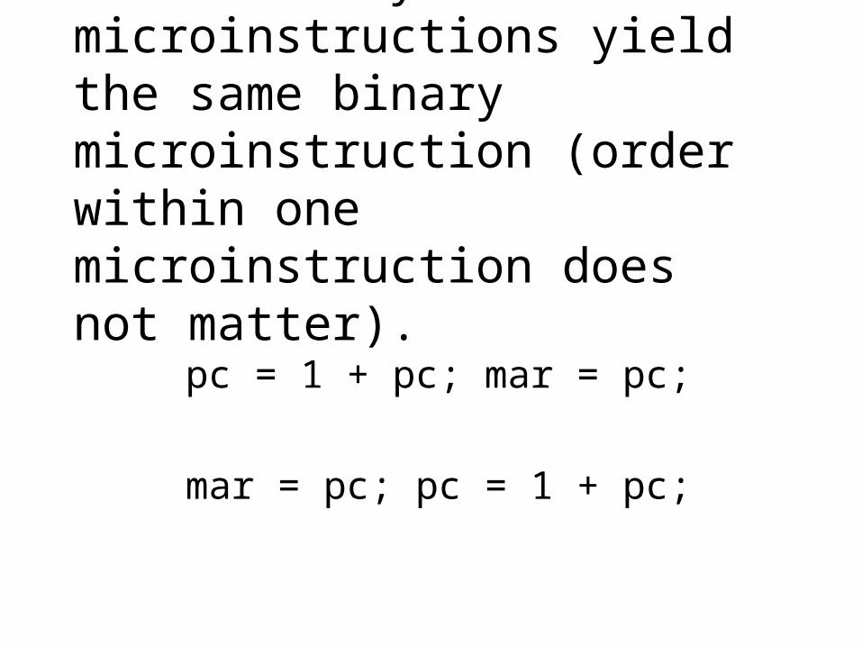
These two symbolic microinstructions yield the same binary microinstruction (order within one microinstruction does not matter).
pc = 1 + pc; mar = pc;
mar = pc; pc = 1 + pc;

When is the pc register incremented?
The mar is loaded at T2. The pc is loaded at T3. Thus, the mar is loaded from the pc before the pc is incremented.
pc = 1 + pc; mar = pc;

Writing microcode
• We write microcode in symbolic form.
• But H1 needs the binary form.
• So we translate the symbolic form to binary using the microassembler has.
• “.has” extension is for symbolic microcode
• “.hor” extension is for binary microcode
• Hex form is a shorthand representation of the binary form.


Problem 6.22 Microcode Decode Section

Multiple shifts are inefficient with the simple one-position shifter. Better: use a barrel shifter.
H1 has a barrel shifter but it is not the default shifter.
Configuration file
To use new microcode, you must provide a configuration file that describes the microcode. The configuration file is used by mas, has (the microassembler), and sim.


!-directive
• Placed at the beginning of a machine-level assembly language program.
• Indicates the microcode/configuration file to use.
• For example, !b indicates that b.hor (microcode file) and b.cfg (configuration file) should be used.

bprog.mas—a test program for the basic instruction set microcode.

Using new microcode b.has with configuration file b.cfg
• Assemble microcode: has b (translates b.has to b.hor). has responds with Reading configuration file b.cfg
• Assemble test program: mas bprog (translates bprog.mas to bprog.mac). mas responds with Reading configuration file b.cfg
• Run bprog on sim: sim bprog sim responds with Reading configuration file b.cfg Reading microcode file b.hor

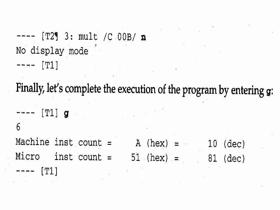
Running bprog.mac on sim.
We will examine its execution at both the machine and microlevels.

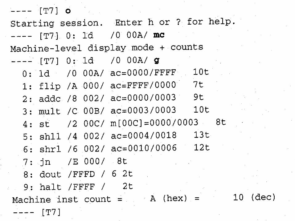

To trace microcode, H1 must be enabled. Debugger commands then become case sensitive: uppercase for the machine-level;lower case for the microlevel.

T2 executes 2 machine instructions

Lower case m changes display mode to microlevel
Upper case T1 executes 1 machine instruction. When in micro display mode, all the microlevel activity during the execution of this machine instruction is traced.
The default command when in micro display mode is T1.

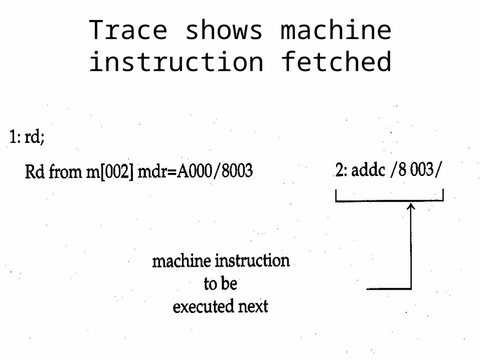
Trace shows machine instruction fetched
Lower case t3 executes 3 microinstructions
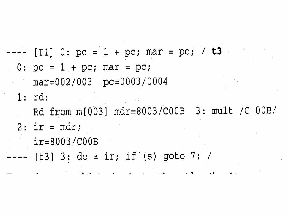

Lower case u0 unassembles microcode in microstore starting from location 0.

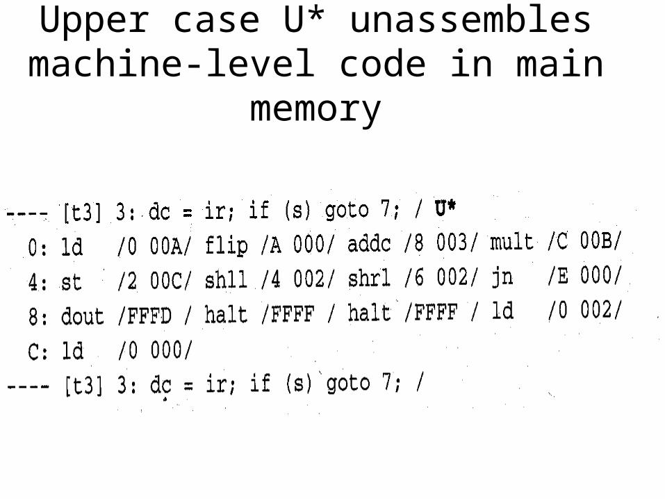
Upper case U* unassembles machine-level code in main memory

Lower case d* displays all of microstore in use.
Upper case D* displays all of main memory in use.


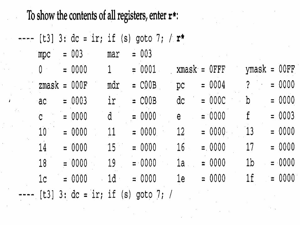
Lower case r* displays all registers.

Upper case R* shows machine-level registers
Upper case M returns to machine-level display

Now back to machine-level display
N turns off trace (N is always case insensitive).
To write more efficient microcode, interleave instruction execution with decoding
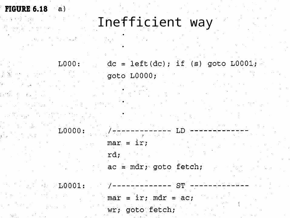
Inefficient way

More efficient way

Using a barrel shifter
• Specify two register operands for the left or right operations.
• Simple shifter: ac = left(ac);
• Barrel shifter: ac = left(ac, ir); Then the rightmost 4 bits of ir provide shift count.

Hardwired control
• Less flexible than microcoded control.
• Generally faster than microcoded control because does not involve the fetching of microinstructions.
• Can be very costly for a complex instruction set.
• Hardwired control typical of RISC.

Hardwired control

Horizontal versus vertical microcode
Horizontal Microinstruction: 32 bits
Vertical microinstruction: 19 bits
sim supports both horizontal and vertical microcode. H1 is the horizontally microcode machine; V1 is the vertically microcoded machine.

To run sim with the built-in vertical microcode use the /ver command line argument.
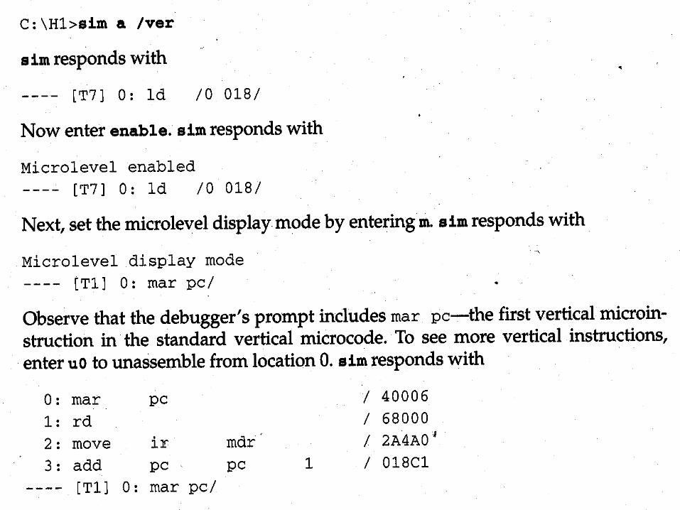

In V1, ADDR and the A/B fields overlap—this reduces the size of a microinstruction.


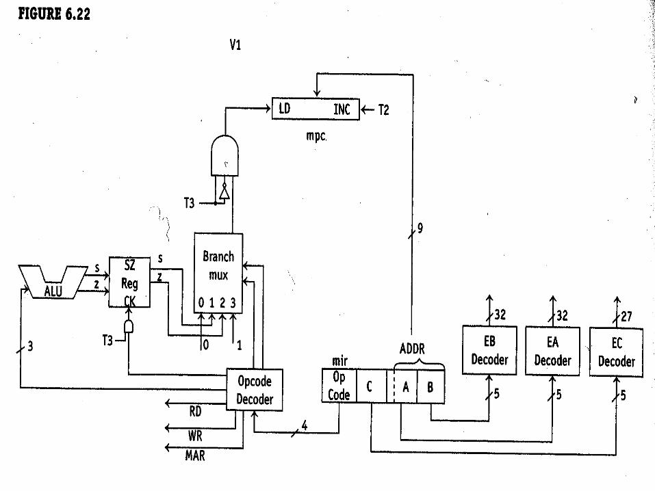
V1 uses additional decoding to reduce the size of microinstructions—an opcode decoder.


Opcode decoder
• 4-bit input
• 7 bits out: MAR, WR, RD, ALU function, SZ enable
• Reduces microinstruction size by 3 bits.

V1 cannot perform a computation and branch in one microinstruction. So the ALU output during a computation must be saved (in the SZ register) for a subsequent branch instruction.
See the next slide.

The basic instruction set requires more microinstructions in vertical microcode than in horizontal microcode (because one vertical instruction, in general, does less than one horizontal microinstruction.


Using new vertical microcode b.vas with configuration file b.cfg
• Assemble microcode: vas b (translates b.vas to b.ver). vas responds with Reading configuration file b.cfg
• Assemble test program: mas bprog (translates bprog.mas to bprog.mac). mas responds with Reading configuration file b.cfg
• Run bprog on sim: sim bprog /mb.ver sim responds with Reading configuration file b.cfg Reading microcode file b.ver

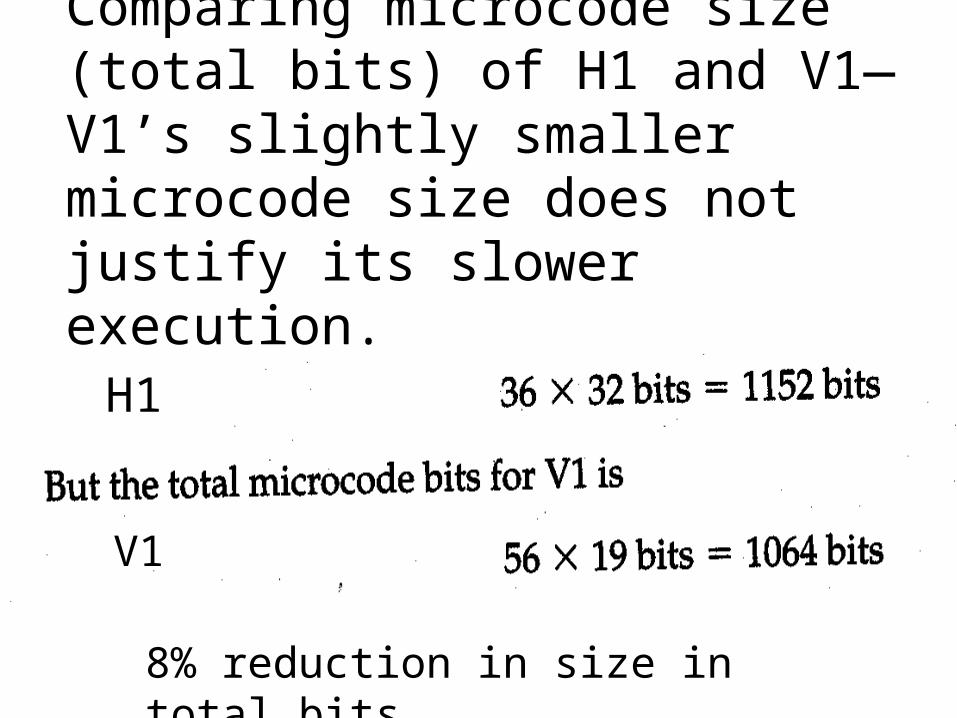
Comparing microcode size (total bits) of H1 and V1—V1’s slightly smaller microcode size does not justify its slower execution.
H1
V1
8% reduction in size in total bits
Related Documents


![CSC 110 Decision structures [Reading: chapter 7] CSC 110 H1.](https://static.cupdf.com/doc/110x72/56649c765503460f9492a2cb/csc-110-decision-structures-reading-chapter-7-csc-110-h1.jpg)