Chapter 6 Implement Threat Control Measures

Chapter 6
Dec 30, 2015
Chapter 6. Implement Threat Control Measures. After identifying vulnerabilities and threats Implement threat control measures. Identify level of protection. Initial risk exposure – Factor 1 Vulnerability and threat analyses (chapter 5) produced the initial risk exposure, - PowerPoint PPT Presentation
Welcome message from author
This document is posted to help you gain knowledge. Please leave a comment to let me know what you think about it! Share it to your friends and learn new things together.
Transcript

Chapter 6
Implement Threat Control Measures

• After identifying vulnerabilities and threats• Implement threat control measures

Identify level of protection• Initial risk exposure – Factor 1• Vulnerability and threat analyses (chapter
5) produced the initial risk exposure, • Identify the severity and likelihood of each
vulnerability/threat pair with critical threat zones
• Threat control measures implemented to reduce the initial risk exposure to the desired target.

Identify level of protection
• Identify the IA-critical IA-related system entities and functions – Factor 2
• IA-critical – performance is essential to the safe, reliable, and secure operation and support of a system.
• IA-related - a system or entity that performs or controls functions which prevent or minimize the effect of failure of an IA-critical system or entity.
• See Exhibit 4 Page 132• Correlate to the initial risk exposure
– What is risk to IA critical and IA related functions

Identify level of protection
• Factor 3 – Specify Must Work Functions (MWF) and Must Not Work Functions (MNWF)
• MWF - software that if not performed or performed incorrectly inadvertently, or out of sequence could result in a hazard or allow a hazardous condition to exist.
• MNWF is a sequence of events or commands that is prohibited because it would result in a system hazard.

Identify level of protection
• Hazard and operability (HAZOP) study identifies MNWF’s
• Neglecting to specify MNWF’s creates an opportunity for serious vulnerabilities.
• See Exhibit 5. Page 134

• Factor 4 – Entity control analysis (exhibit 6 page 79)
• Carefully review entity-control analysis to eliminate any point of failure
• Review control of entities over MWFs and MNWFs

Level of protection
• Factor 5 - Time Element• Time element should not be ignored • Two aspects of the time element to
evaluate1) the time window during which the protection
is needed,
2) the time interval during which the proposed threat control measures will be effective.

Level of protection
• Factor 6 – Privacy• Re-examine privacy issues in light of
systems design, operation and operational environment
• Ensure that corporate or organizational assets, intellectual property and information is protected

Level of protection
• Analysis and synthesis of six factors– Risk exposure reduction needed is identified– Estimated level of protection is identified
• IA integrity level defined for the system

Level of protection
• IA integrity level represents the level of IA integrity that must be achieved or demonstrated to maintain the IA risk exposure at or below its acceptable level.
• There are five levels of IA integrity4 – Very High3 – High2 - Medium1 – Low0 – None

IA integrity levels• used to:
1) prioritize the distribution of IA resources2) to select appropriate threat control measures based
on the type, level, and extent of protection needed.• IA integrity levels reflect confidence that a
system will achieve and maintain required– safety, – Security– reliability under all stated conditions so that the risk exposure is
maintained at or below the target • a measure of the robustness of a system’s IA
features and the process(es)

Evaluate Controllability
• Any aspect that enhances safety, security and reliability must be considered for threat control
• Examine people• People have the potential to influence system integrity in
a positive manner.• Controllability is measure of the ability of human
action to control the situation following a failure.• Controllability
– human-assisted form of fault tolerance or failing safe/secure. – Design provisions such as manual override, emergency
shutdown, critical bypass, etc.• See Exhibit 6 page 138

Evaluate Operation Procedures
• Procedures are developed for each operational mode/state– normal operations, – abnormal operations, – and recovery,
• If developed and followed correctly operation procedures contribute to systems integrity.
• Opposite is also true

Contingency Planning and Disaster Recovery
• Integral part of risk management and implementing threat control measures
• Contingency plans identify – alternative strategies to be followed or actions to be
taken to ensure ongoing mission success – should unknown, uncertain, or unforeseen events
occur.
• Contingency planning assumes worst-case scenarios.

Contingency Planning
• Steps in Contingency Planning– Identify all internal and external system entities and the
degree of control: system definition and entity control analysis (Chapter4)
– Identify what would go wrong with a system and its entities: the failure points/ modes and loss/ compromise scenarios.
– Vulnerability/threat characterizations, transaction paths, and critical threat zones (chapter 5) are analyzed during the process.
• See exhibit 7 page 141 and Exhibit 8 page 142

Contingency Planning
• Appropriate response for each contingency is defined, consistent with the IA goals and IA integrity level.
• Alternative courses of actions and identifying alternative system resources.
• Priorities are established for restoring and maintaining critical functionality
• The availability alternatives sources, services, and resources are specified
• See exhibit 9 page 144

Contingency Planning
• Assign responsibility for deploying the alternative course of action and resources.
• Next, the maximum time interval during which the responsive action can be invoked is defined.
• Identify secondary courses of action/resources to invoke, if the maximum time interval for the primary response is exceeded.

Contingency Planning
• Plans must be communicated and staff must be trained.
• Practice drills should be conducted regularly to– familiarize staff with the plan’s provisions– uncover any defects in the plan.
• Contingency plans should be revived, updated,
and revalidated at fixed intervals.

Perception Management
• Systems owners want users to perceive that the system is safe, secure and reliable
• Obvious benefits to the organization• Also serves as a deterrent to potential attackers• System is perceived to be difficult to attack• Do not go overboard and make it challenging to
the attacker

Perception Management
• Deploy Decoys that look authentic– decoy servers– decoy screens– decoy files/data– decoy passwords
• Security trap to lure would be attackers• Lure attackers away from critical data• Effective method of blocking a DoS attack
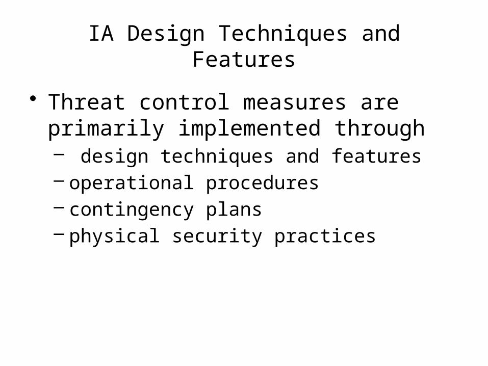
IA Design Techniques and Features
• Threat control measures are primarily implemented through – design techniques and features – operational procedures – contingency plans– physical security practices

IA Design Techniques and Features• Threat control measures chosen in response to
specific vulnerabilities, hazards, and threats.
• Goal of threat control measures - reduce the initial risk exposure to at or below the target.
• Design techniques and features are a collection of methods by which a system (or component) is – designed – and capabilities are added to a system to enhance IA
integrity.• See Exhibit 10 – page 146

Access control• Access control
– a design feature that prevents unauthorized and unwarranted access to • Systems • applications • data • resources
• Access controls should be operative at all layers of the OSI and networking protocols.
• Access control mechanisms are activated immediately after authentication.

IA Design Technique - Access control
• An initiator (person or process) request to perform an operation on a target resource.
• Access control mechanisms mediate requests based on predefined access control rules.
• Access control rights – initiator/ resource combination
• access privileges– initiator/operation combination

Access controlAccess control can be defined in 3 ways• Access control lists
– specify the approved initiator(s) for each (group of) target(s)
• Access capability lists – specify the target(s) accessible to a (group of)
initiator(s)
• Security labels, – each initiator and target is assigned to one or more
security label (confidential, secret, top secret, etc.) Labels define access control rights and privileges

Access control
• Develop Access control rules– First start with a general list of all Initiators, their
operations and the resources each uses– Develop a matrix of initiators and resources
indicating operations performed on a particular resource – Control List
– Rotate the matrix to develop Access Capability list – Operations and initiators
– Security Labels – group initiators with certain security clearance have same access control rights/privileges
See Exhibit 14 – page 157

Access control
• Invoke default “access denied” if the system encounters an unknown or undefined state.
• Access control rules should be regularly reviewed, updated and revalidated.
• Protect files defining access control rules from unauthorized access and modification.
• Define who has the right to update/modify the access control rules, in both normal and abnormal situations.

Access control
• Access control rights - time of access:– User/process may be allowed to access certain
system resources only at certain times during the day.– User/process may only be allowed to access system
resources during a specified time interval after their identity has been authenticated.
– Time-sensitive information may only be accessed “not before” or “not after” specific dates and times.
– E-mail, public keys, and other security tokens may have built-in (hidden) self-destruct dates and macros.

Access control
• Access control - physical access control– control of and accountability for portable systems and
media– physical access to
• desktop PC’s • Servers• cable • Plants• shared printers• Archives• hardcopy outputs

IA Design Technique - Account for all possible logic states
• Method to prevent a system from entering unknown or undefined states – potentially unstable, – compromise IA integrity
• All logical states are defined for each critical decision point or command
• Once the logic states have been identified, an appropriate response is defined for each of the following states– continue normal operations– trigger alarm– request further input/clarification– emergency shutdown

Account for all possible logic states
• Implementing an OTHERWISE or default clause to trap exceptions or transient faults
• This technique should be applied to all types of software: System software, application software, firmware, etc.
• Useful for uncovering missing and incomplete requirements
• See Exhibit 15 Page 160

IA Design Technique - Audit trail
• Provides several IA integrity functions– Capturing information about
• which people/processes accessed • what system resources• when.
– Capturing information about system states and transitions and triggering alarms if necessary.
– Developing normal system and user profiles for intrusion detection systems.
– Providing information with which to reconstruct events during accidents/ incident investigation.

Audit trail• Audit trail provides real-time and historical logs
of – system states– Transitions– resource usage.
• When a system compromise is expected, a security alarm is triggered.
• Alarm contents and primary and secondary recipients are defined during implementation.

Audit trail
• Components of a security alarm– Identity of the resource experiencing the security event– Date/ timestamp of the security event– Security event type (integrity violation, operational violation,
physical violation, security features violations, etc.)– Parameters triggering the alarm– Security alarm severity (indeterminate, critical, major, minor,
warning)– Source that detected the event– Service user who requested the service that led to the
generation of the alarm– Service provider that provided the service that led to the
generation of the alarm

Audit trail
• An audit trail consumes system resources; thus, carefully determine what events to record and how frequently they should be recorded.
• Determination also has to be made about the interval at which audit trail should be archived and overwritten.
• Protect Audit trails from unauthorized access.

IA Design Feature - Authentication
• Accurate authentication is an essential first layer of protection.
• Access control, audit trail, and intrusion detection functions depend on authentication.
• Authentication methods: – Unilateral– Mutual– digital certificates– Kerberos – Data origin– Peer entity– Smartcards– Biometrics.

Authentication
• Unilateral Authentication– When a user logs onto a system, the user is
authenticated to the system but the system is not authenticated to the user.
• Mutual authentication– mutual authenticated in which both parties (users,
processes, or systems) are authenticated to each other before any transactions take place. E.g. E-Commerce
• A challenge-response protocol is commonly used to perform mutual authentication.

Authentication
• Data origin authentication ensures that messages received are indeed from the claimed senders and not an intruder who hijacked the session.
• Data origin authentication is initiated after an association setup is established and may be applied to all or selective messages.
• Smartcards are a physical security token that a user presents during the authentication process.
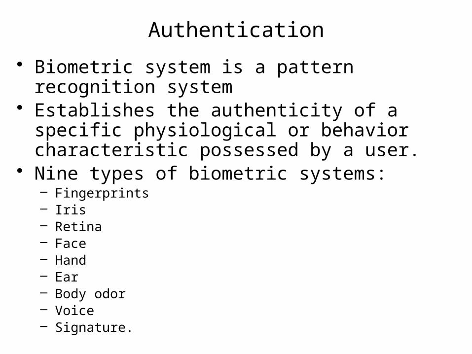
Authentication
• Biometric system is a pattern recognition system • Establishes the authenticity of a specific
physiological or behavior characteristic possessed by a user.
• Nine types of biometric systems: – Fingerprints– Iris– Retina– Face– Hand– Ear– Body odor– Voice– Signature.

IA Design Technique - Block Recovery
• Provides correct functional operation in the presence of one or more errors.
• Implemented to increase the integrity of modules that perform critical functions.
• Each critical module has a primary and secondary module
• See Exhibit 17 Page 168
• After the system has been reset, normal operation continues.
• Forward block recovery for anticipated errors• Backward block recovery for unanticipated errors.
IA Design Feature - Confinement• Restricts an un-trusted program from accessing
systems resources and executing systems processes
• Goal – Non-interference between independent functions that utilize shared resources and unintended inter-component communication
• Interference:– Data Corruption – overwriting vital data stored in
common memory and used by trusted components– Denial of service to critical resources – Untrusted
components prevent or delay execution of critical shared resources, take too much CPU processing time

Confinement• Implement confinement by
– Restrict a process from reading data it has written
– Limit executable privileges to the minimum need to perform functions. Example: child processes do not inherit privileges of the parent
– Mandatory Access Control (MAC)
– Domain and type enforcement (DTE)• Domain associated with each subject (user or process)• Type is associated with each object (systems resource)• Matrix is defined
– Wrappers • encapsulates data from view to anyone other than the intended
recipient.

IA Design - Defense in Depth
• Providing several overlapping subsequent limiting barriers
• Threshold can only be passed if all barriers fail
• Reflects common sense• Everything is done to prepare for known
potential hazards and vulnerabilities• See Exhibit 18. Page 171

IA Design – Defensive programming
• Prevents systems failures or compromises by detecting errors in control flow, data flow and data during execution
• Reaction in a predetermined and acceptable manner
• Applied to all IA-critical and IA-related functions

Defensive programming
• Approached from 2 directions• Potential software design errors are
compensated– Range, plausibility and dimension checks are
performed at procedure entry and before executing critical commands
– Separate read-only and read-write parameters to prevent overwriting

Defensive programming
• Anticipate failures in the operating environment– perform control flow sequence checks to detect
anomalous behavior : state transitions– regular verification of hardware and software
procedures– conduct plausibility checks on critical input,
intermediate and output variables before acting upon them
• All actions and transitions are verified beforehand are a preventive strategy

Plausibility Checks
• Enhances IA integrity by verifying the validity and legitimacy of critical parameters before acting upon them
• Detects faults in the execution cycle and prevents them from progressing into failures
• Value of parameters that affect IA critical and IA related functions are checked.
• See examples on page 191

IA Design Technique Degraded-mode Operations
• Purpose to ensure functionality of critical functions is maintained in the presence of one or more failures
• In the event of anomalous behavior, suspected attacks or compromise IA-critical and IA-related functions can rarely cease to operate
• Priorities are established for maintaining critical functions and dropping less critical ones
• Total system (hardware, software and communication equipment) is considered for planning degraded-mode operations

Degraded-mode Operations
• Tied directly to operational procedures of contingency plan
• Specify IA-critical and related functions during requirements and design phase
• Criteria for transitioning in degraded-mode• Define maximum time period system is
allowed in degraded mode

Degraded-mode Operations
• Intermediate state between full operation and total system shutdown
• Another preventive strategy to plan response for potential crisis situations

Digital Signatures
• Provide nonrepudiation of origin• Created using public key encryption• Involves a signature generation and
signature verification algorithm

Digital Signatures
• Consists of a fixed length string of bits that is derived from the original message
• Message is encrypted, signature attached and message is transmitted
• Recipient decrypts the string to verify the string reflects the original message
• Recipient signs the message and returns it to the sender – roundtrip confirmation
• Used in e-commerce

Diversity
• Enhances IA integrity by detecting and preventing systematic failures
• Implemented in hardware and software• Software diversity – n-version
programming– More than one algorithm is developed to
solve the same problem– Same input and outputs are compared– Agreement can be 100% or majority –
depends on the criticality of application

Diversity
• Software diversity (continued)– Error detection and recovery algorithms – if
results don’t agree– Diverse software can execute in parallel on
different processors or sequentially on the same processor

Diversity
• Hardware diversity– Multiple, different components and modules
to perform the same function– Not hardware redundancy – multiple units of
the same hardware are employed– Components and modules are chosen that
have different rates and types of failures

Encryption
• Provides confidentiality of data while stored and transmitted
• Manipulating string of data (clear text) according to a specific algorithm to produce cipher text
• What data needs encryption – derived from IA goals
• Identify data that does not need encryption – only certain fields in a database may be encrypted

Encryption
• Where is the Data stored, created and transmitted?– for efficient and effective encryption strategy
• Encryption strength needed?– low to medium for random office e-mails– high to very high for defense or intelligence
applications

Encryption
• At what level of the OSI or TCP/IP reference model should encryption take place?– Encryption can be implemented at the
physical, data link, network, transport and application layers
– See Exhibit 20 page 176

Encryption
• Hardware or software encryption?• Hardware encryption for critical
applications• Hardware encryption
– designed to be tamperproof– erase keys if tampering is detected– eliminate examinations through shielding– faster than software encryptions: offloads
intensive calculation from the CPU

Encryption
• Software encryption– easy to use and upgrade– Vulnerability – can be preempted by a high-
priority task. Data and key exposed– Key management is an issue

Encryption
• Block or stream ciphers?• Block ciphers
– operate on a fixed number of bits or bytes– cipher text and clear text have the same block size– can be implemented in hardware or software
• Stream Ciphers– operate on asynchronous bit streams– Transform a single bit or byte of data at a time– Implemented in hardware at the data link level
Encryption
• Mode of block or stream cipher operation?• Five most common modes
– Electronic code book (ECB)– Cipher Block chaining (CBC)– Output feedback (OFB)– Cipher feedback (CFB)

Encryption• Choice of encryption key type – symmetric or
asymmetric?• Symmetric or secret key – same key used for
encryption and decryption– Sender and receiver known to each other– Sender and receiver remain constant for a fixed
period of time– Sender and receiver nodes remain constant– Long-term relationship anticipated – regular need for
exchange of sensitive information– sender and receiver have the ability to co-operate on
key management and encryption issues.

Encryption
• Asymmetric keys uses a pair of public and private keys.
• Public key used for encryption is shared• Private key used for decryption is not
shared• Both keys are mathematically related but
not feasible to uncover private key from public key

Encryption
• Asymmetric keys – A wants to send B a sensitive message– A encrypts the message with B’s public key– B decrypts the message with their private
keys• Most organizations employ a combination
of symmetric and asymmetric keys

Encryption
• Key Management ?• Most encryption algorithms are publicly
available• Keys must be protected• Protection proportional to the sensitivity of
information

Encryption• Key management procedures for
– Key generation– Key distribution– Key verification– Controlling the use of keys– responding to key compromise– Changing keys – Storing keys – Key recovery, backup– Destroying old keys
• Policies must be established with involvement of all stakeholders
• Adequate training• Periodic audits and review of established procedures
and policies
Encryption
• Encryption algorithms?• Strength of encryption depends on the
strength and sophistication of encryption algorithm and length of key

Error detection/Correction
• Algorithms used to – increase data integrity during transmission– Increase systems integrity during execution of
application software
• At network level error detection/correction algorithms examine data – for accidentally lost or corrupted data– for intentional unauthorized changes to data
• Self correcting codes or requests for retransmission are initiated if errors are detected

Error detection/Correction
• At application software level error detection/correction algorithms – detect anomalous or illegal modes/states,
parameters– initiate appropriate error handling routines

Fail safe/secure
• Ensures that a system remains in a known safe/secure state following an irrecoverable failure
• A component automatically places itself in a known secure state in the event of a failure
• Safe default values are assumed• System is brought in a safe/secure state
by shutting it down

Fail operational
• System or components continue to provide limited critical functionalities in even of failure – e.g. aircraft flight control system
• Fail safe/secure and fail operational are proactive features to respond to predictable failures
• See fail operations – Page 182

Fault tolerance
• Increases IA integrity by providing continuous correct execution in the presence of a limited number of hardware and software faults
• Focuses on containing the mitigating consequences of faults – not preventing them
• Error (correct value or condition) or mistake (error in human action) leads to a fault which leads to a failure

Fault tolerance
• Fault tolerance attempts to prevent faults from progressing to a failure
• Three types of fault tolerance– Hardware: generated by design errors,
environmental factors, physical degradation– Software: design errors and runtime errors– Systems: combination of hardware and
software

Firewalls, Filters
• Firewalls control access between one network and another
• Firewalls monitor both incoming and outgoing traffic
• Three types of firewalls– Packet filters– Application level gateway– Circuit level gateway

Firewalls, Filters
• Packet filters– determine is a packet should be allowed to
enter the network depending on the destination address, source
– Enabled by filtering rules• Application Gateways
– Protect specific applications – e.g. e-mail servers
– All traffic logged

Firewalls, Filters
• Circuit level gateways– also called proxy firewalls– mediate between two devices trying to communicate
between firewalls– A caller connects to a port on the outside gateway. If
session approved, gateway forwards information to the destination that is connected to the internal gateway port.
– Logs the number of bytes sent by the TCP address– Not effective against insider attacks

Formal specifications, Animated specifications
• Mathematical techniques in specification, design and verification of hardware and software
• Formal notations based on discrete mathematics to specify and verify systems requirements and design
• Subject to rigorous mathematical analysis to detect inconsistencies, incorrectness and incompleteness
• Similar to a compiler for checking syntax errors, analysis performed with toolsets

Formal specifications, Animated specifications
• Can be animated to illustrate specified systems behavior, validate requirements or need for clarifications and correctness
• Compensate the weakness inherent in natural language specifications – ambiguity, misunderstanding due to multiple interpretations
• Primary use – to verify the security kernel correctly implements a specified policy and model
• Advantages– Incorrect specifications lead to vulnerabilities– Serious errors corrected in the design phase– Formal specifications for access control and operational states
of IA critical and IA related functions

Information hiding
• A software development technique in which– each modules interface reveal a little as possible about
the module’s innerworkings– other modules are prevented from using information about
the module that is not in the module’s interface specifications
• Can be applied to data and programming logic• Data structures are localized and as self-contained
as possible• Data and programming logic can be changed without
affecting other modules

Intrusion Detection, Response
• Recognize and respond to security breach– as it is happening – immediately after it has happened
• Operate behind a firewall• Part of defense in depth• Detect insider and outside attacks

Intrusion Detection, Response
• Three types of ID/R systems– Statistical anomaly detection
• Analyzes audit trail data for abnormal user or system behavior
• Compares current audit trail data against historic data
• Disadvantages – historical data contains undetected intrusion, anomaly
treated as normal.– Attacker knows the normal behavior and fools the
system– Normal profiles are defined too loose or tight, false
positives or false negatives may be triggered

Intrusion Detection, Response
• Types of ID/R– rule based detection
• Monitors audit trail data for patterns of activity that match known attack profiles
• Weakness– only know attacks are identified– Library of know attacks must be frequently updated
– Hybrid• Combination of statistical anomaly and rule based

Intrusion Detection, Response
• How to respond in an attack– Option 1: system could automatically respond
with no human intervention– Option 2: Like audit trail, security alarm that
requires human intervention. Primary and secondary receipts must be defined and the time interval for action to be taken
– Option 3: System automatically responds if no human action occurs within a specified time interval.

Partitioning• Prevents
– non IA-critical functions/entities from accidentally corrupting or interfering IA critical and IA related functions
– non IA-critical functions/entities from being used a vehicle for intentionally corrupting IA critical and IA related functions
• Advantages– reduces efforts required to verify IA critical and
related functions– resources can be focused on the most critical
elements– Minimizes potential faults from affecting the system
Redundancy
• Fault tolerance technique to increase hardware reliability and system availability
• Identical components are used to perform identical functions
• Hardware redundancy implemented in three ways– Active
• multiple identical secondary units operating simultaneously
• If fault detected in primary, operations switched to “hot” secondary

Redundancy
• Hardware Redundancy– Standby
• Redundant “cold” secondary is operational only after fault has been detected in the primary
– Monitored redundancy • A variation of active redundancy• monitors the output from all parallel components• if discrepancies are found, voting logic is activated
to determine which output is correct and what action should be taken (switching)

Reliability allocation• Distributes reliability and maintainability
requirements among systems entities• First Step
– Assign a numerical reliability requirement to systems entities and components
– Consider sub-systems, components and sub-components
– factors to be considered• operational mode (continuous or demand)• Duty cycle• Criticality in relation to stated IA integrity level• Complexity• Uncertainty of operating environment• historical experience

Reliability allocation
• Step 2– Determine the maintainability requirements needed
to support the reliability requirements– consider same factors
• Step 3– Calculate systems reliability and maintainability from
individual components– Reverse of first step (only systems reliability was
calculated)– Combine the values of each component and
compare with the value of the system reliability

Reliability allocation
• Step 4– Component reliability and maintainability
requirements are refined by an iterative process of reallocation and recalculation until the IA goals are met
– Reliability prediction models, block diagrams and BBN’s are used

Secure protocols
• Enhance confidentiality of distributed data communications
• Provide security services not available through basic communication protocols such as TCP, IP etc
• Address interoperability issues related to implementing security features such as digital signatures, algorithms to sign and encrypt messages, key sharing and authentication
• Current secure protocols – IPSec, NLS, TLS1, SSL3, SET, PEM, PGP etc.

Virus Scanners
• Automatically detect and remove viruses• Virus classifications
– Boot virus: attack the boot sector of the hard disk or floppy disk when powered on
– Macro virus: embedded in word processing documents or spreadsheets as macros. Activated when macros are executed
– Program viruses: viruses that attach to and attack *.exe, *.com, *.sys, and *.dll files when executed
– Transient viruses: viruses that are active only when the infected program is executing
– Resident viruses: viruses that remain in memory and link themselves to the execution of other programs

Virus Scanners
• Types of Virus Scanners– Activity monitors
• similar to intrusion detection systems they look for suspicious activity patterns that could indicate the presence of virus activity
– Change Detection or integrity monitors• flag systems and user files that have been
changed• Generate a lot of positive flags unless provided a
legitimate method for flagging changes

Virus Scanners
– Pure scanners • scan systems and user files, boot sectors and
memory for evidence of known infections
– Hybrid scanners • A hybrid of all three types• Most virus scanners are hybrid
Related Documents