Chapter 5 The Cytoskeleton and Cellular Architecture George Plopper

Chapter 5 The Cytoskeleton and Cellular Architecture George Plopper.
Dec 17, 2015
Welcome message from author
This document is posted to help you gain knowledge. Please leave a comment to let me know what you think about it! Share it to your friends and learn new things together.
Transcript

Chapter 5
The Cytoskeleton and Cellular Architecture
George Plopper

iClicker TimeWhich statement best defines a fusion protein?
A) One that contains the amino acid sequences of two different polypeptides in one polypeptide.B) One that contains both alpha helices and beta sheets.C) One that can be visualized by both a phase contrast microscope and a fluorescence microscope.D) One that can bind to more than one different target molecule.E) One that can be recognized by antibodies from more than one species of animal.
iClicker TimeIf we immunoprecipitate a kinase protein to study its function, and use a primary antibody to capture it, what is the best way to release the kinase protein from the heavy/magnetic bead?A) Add a different kinase protein to the beads, so it can replace the captured kinase proteins.B) Boil the beads in physiological saline, so the increased heat will dislodge the kinase proteins.C) Add more magnetic beads to the solution to bind any excess antibodies.D) Add a secondary antibody to bind the beads.E) Replace the initial buffer solution used to suspend the kinases with a buffer containing a slightly different pH.

Figure 05.01: The cytoskeleton forms an interconnected network of filaments in the cytosol of animal cells.
Reprinted from J. Struct. Biol., vol. 115, M. T. Svitkina, A. B. Verkhovsky, and G. G. Borisy, Improved Procedures for Electron Microsopic Visualization..., pp. 290-303, Copyright (1995) with permission from Elsevier [http://www.sciencedirect.com/science/journal/10478477]. Photos courtesy of Tatyana Svitkina, University of Pennsylvania.

Figure 05.02: Two types of intermediate filaments.
Photos courtesy of John Common and Birgit Lane, Institute of Medical Biology, Singapore.

Figure 05.03: Intermediate
filaments have the most mechanical strength of the
cytoskeletal proteins.

Figure 05.04: The central rod domain of intermediate
filament proteins forms an alpha helix. The head (and tail) regions form globular shapes.

Figure 05.05A: A model for intermediate filament assembly. The coiled coil formed by the dimer formed the structural basis for the strength of intermediate filaments.

Figure 05.06: Keratin expression patterns vary in different epithelial tissues.

Figure 05.07: Costameres link the contractile apparatus of muscle cells to the plasma
membrane and extracellular matrix.

Figure 05.08: The distribution of microtubules in a human epithelial cell. The microtubules are stained green and the DNA is stained red.
Photo courtesy of Holger Lorenz, Zentrum für Molekulare Biologie der Universität Heidelberg, Germany.

Figure 05.09_TOP: The structure and location of the centrosome.

Figure 05.09_BTM: The structure and location of the centrosome.

Figure 05.10: A three dimensional model of the dimer formed by α- and β-
tubulin.

Figure 05.11: In vitro assembly of microtubules is spontaneous and GTP-dependent. The graph represents the turbidity of a solution of α-β tubulin dimers over time.
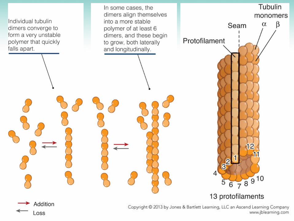

Figure 05.13: Growth and shrinkage of microtubules in a living cell. The microtubules have been tagged with a fluorescent molecule, and recorded by video over time.
Photos courtesy of Lynne Cassimeris, Lehigh University.

Figure 05.14A_TOP: The growth of microtubules begins at the gamma tubulin ring and continues as long as the plus end contains GTP-bound tubulin dimers.

Figure 05.14B: The growth of microtubules begins at the gamma tubulin ring and continues as long as the plus end contains GTP-bound tubulin dimers.

Figure 05.15: Two fates of the plus ends of microtubules.

Figure 05.16: Treadmilling in microtubules.

Figure 05.17: Microtubules exert enough force to move cargo by dynamic instability.
Photos courtesy of Lynne Cassimeris, Lehigh University.

Figure 05.18: Longitudinal and lateral bonds make microtubules strong.

Figure 05.19_BTM: The structure of dynein and kinesis, the two most common motor proteins that bind to microtubules.

Figure 05.19_TOP: The structure of dynein and kinesis, the two most common motor proteins that bind to microtubules.
Photos courtesy of John Heuser, Washington University School of Medicine

Figure 05.20A: How a microtubule motor protein moves along a microtubule.

Figure 05.20B: How a microtubule motor protein moves along a microtubule.

Figure 05.21_BTM: Microtubule motor proteins transport pigment granules in a pigment cell.
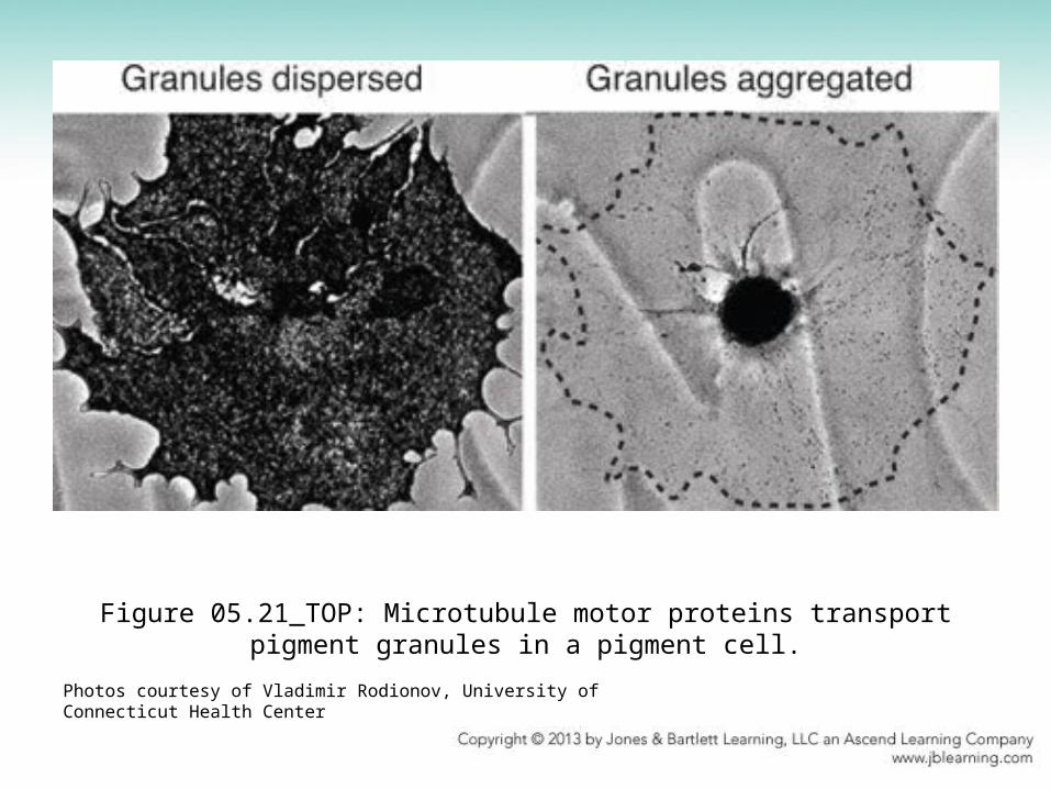
Figure 05.21_TOP: Microtubule motor proteins transport pigment granules in a pigment cell.
Photos courtesy of Vladimir Rodionov, University of Connecticut Health Center

Figure 05.22: A model for bidirectional movement on a microtubule.

Figure 05.25: The general structure of an actin filament. The lateral and longitudinal bonds holding actin monomers together are indicated at right.

Figure 05.25_INS: The general structure of an actin filament. The lateral and longitudinal bonds holding actin monomers together are indicated at right.
Photos courtesy of Ueli Aebi, University of Basel.

Figure 05.26: An electron micrograph of an actin filament partially coated with mysoin proteins.
Photo courtesy of Marschall Runge, John Hopkins School of Medicine and Thomas Pollard, Yale University.

Figure 05.27: A number of different actin filament-based structures in cells. A number of different actin filament–based structures in cells. Neuronal growth cone photos © Schaefer, Kabir, and Forscher, 2002. Originally published in The Journal of Cell Biology, 158: 139–152. Used with permission of Rockefller University Press. Photos courtesy of Paul Forscher, Yale University. Neuronal growth cone photos © Schaefer, Kabir, and Forscher, 2002. Originally published in The Journal of Cell Biology, 158: 139–152. Used with permission of Rockefller University Press. Photos courtesy of Paul Forscher, Yale University.Photo of cell with stress fibers courtesy of Michael W. Davidson and Florida State University Research Foundation. Lamellipodium photo courtesy of Tatyana M. Svitkina, University of Pennsylvania. Filopodia photos reprinted from Cell, vol. 118, M. R. Mejiliano, et al., Lamellipodial versus filopodial mode of the actin . . . , pp. 363–373, Copyright (2004) with permission from Elsevier [http://www.sciencedirect.com/science/journal/00928674]. Photo courtesy of Tatyana M. Svitkina, University of Pennsylvania. Filopodia photos reprinted from Cell, vol. 118, M. R. Mejiliano, et al., Lamellipodial versus filopodial mode of the actin . . . , pp. 363–373, Copyright (2004) with permission from Elsevier [http://www.sciencedirect.com/science/journal/00928674]. Photo courtesy of Tatyana M. Svitkina, University of Pennsylvania./science/journal/00928674]. Photo courtesy of Tatyana M. Svitkina, University of Pennsylvania. Electron micrograph of microvilli © Hirokawa, et al., 1982. Originally published in The Journal of Cell Biology, 94: 425–443. Used with permission of Rockefeller University Press. Photos courtesy of John E. Heuser, Washington University in St. Louis. Scanning micrograph of stereocilia reproduced from A. J. Hudspeth and R. Jacobs, Proc. Natl. Acad. Sci. USA 76 (1979): 1506–1509. Photo courtesy of A. J. Hudspeth and R. A. Jacobs. Electron micrographs of stereocilia © Tilney, DeRosier, and Mulroy, 1980. Originally published in The Journal of Cell Biology, 86: 244–259. Used with permission of Rockefeller University Press. Photos courtesy of Michael J. Mulroy, Medical College of Georgia.

Figure 05.28: The structure of an actin monomer. A ribbon model, derived from a crystalized form of the protein.
Structures from Protein Data Bank 1ATN. W. Kabsch, et al., Nature 347 (1990): 21-22.

Figure 05.29: The three stages of actin filament assembly in vitro.
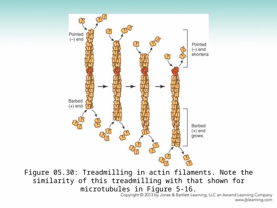
Figure 05.30: Treadmilling in actin filaments. Note the similarity of this treadmilling with that shown for microtubules in Figure 5-16.

Figure 05.31: The structure and function of profilin, an actin monomer-binding protein.
Structure from Protein Data Bank 2ITF. J. C. Grigg, et al., Mol. Microbiol. 63 (2007): 139-149.

Figure 05.32: ARP2/3 nucleates the formation of a new actin filament off the side of an existing filament.

Figure 05.33: Actin crosslinking proteins are organized into three groups, based on the way they bind actin filaments

Figure 05.34: Three forms of crosslinked actin filaments created by different crosslinking proteins

Figure 05.35: Different forms of actin in stationary and migrating cells. Reproduced from A. Hall, Science 279 (1998): 509-514 [http://www.sciencemag.org]. Reprinted with permission from AAAS. Photos courtesy of Alan Hall, Memorial Sloan Kettering Cancer Center, New York.
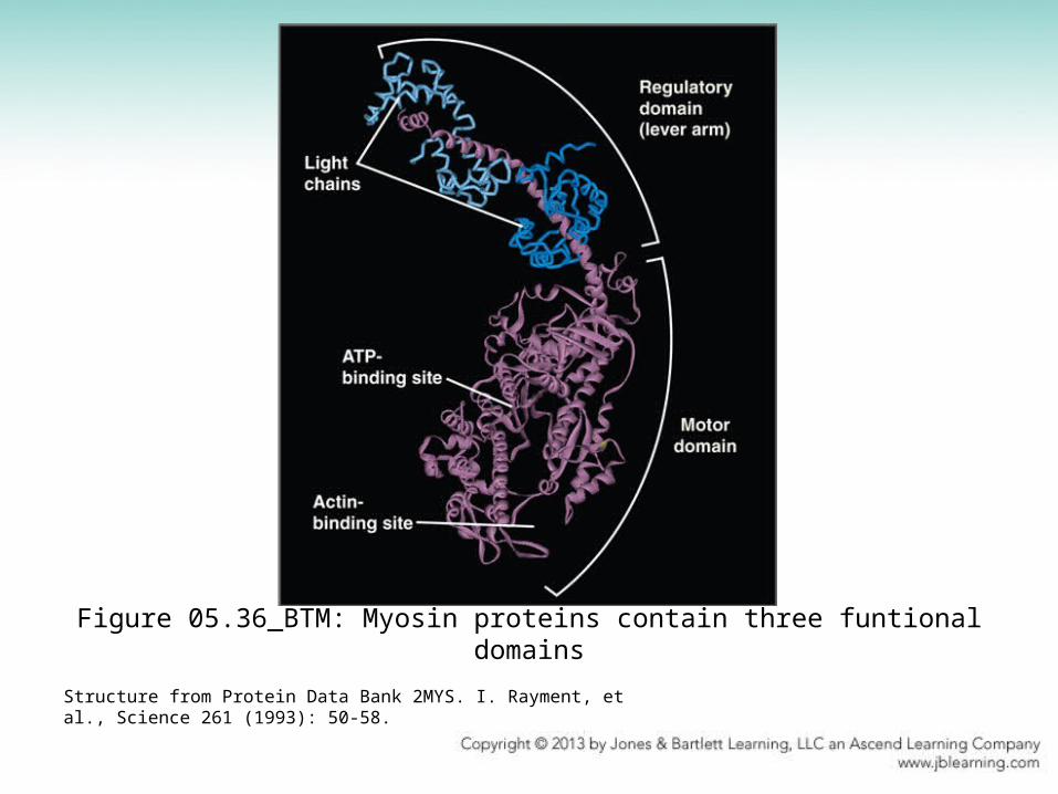
Figure 05.36_BTM: Myosin proteins contain three funtional domains
Structure from Protein Data Bank 2MYS. I. Rayment, et al., Science 261 (1993): 50-58.
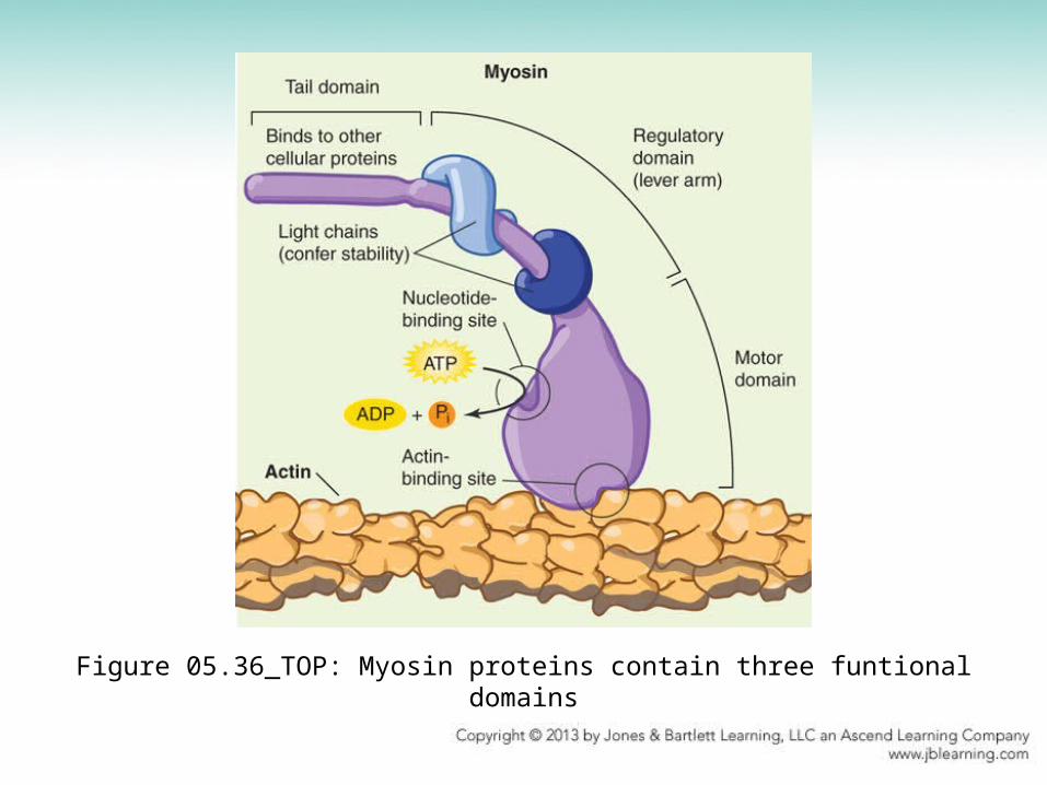
Figure 05.36_TOP: Myosin proteins contain three funtional domains

Figure 05.37: The contractile cycle of myosin.

Figure 05.38_BTM: The anatomy of a skeletal muscle.The sarcomere contains actin and myosin arranged in parallel bundles.
Photo courtesy of Clara Franzini-Armstrong, University of Pennsylvania, School of Medicine.
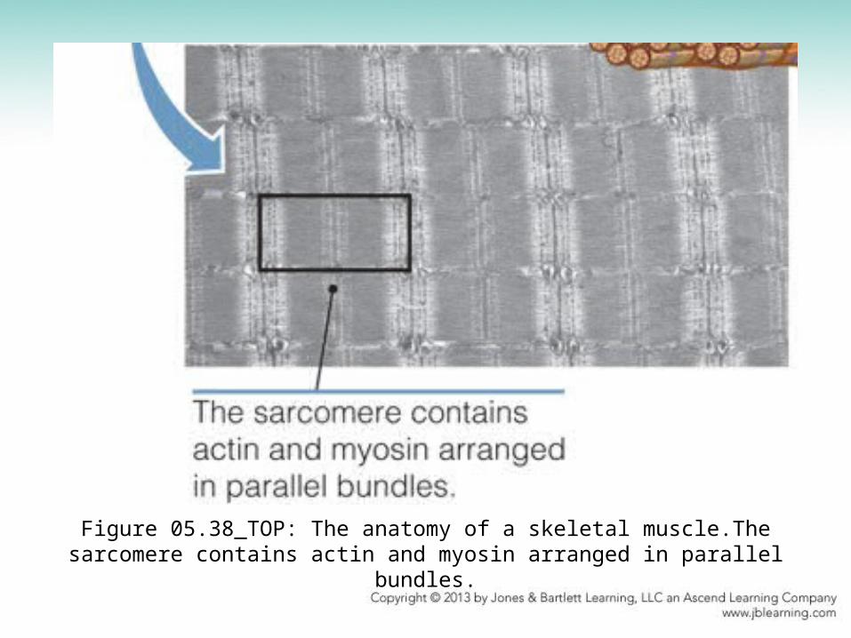
Figure 05.38_TOP: The anatomy of a skeletal muscle.The sarcomere contains actin and myosin arranged in parallel bundles.
Related Documents