Chapter 5 Link Layer Link Layer 5-1 Computer Networking: A Top Down Approach 6 th edition Jim Kurose, Keith Ross Addison-Wesley Chapter5_1

Chapter 5 Link Layer Link Layer5-1 Computer Networking: A Top Down Approach 6 th edition Jim Kurose, Keith Ross Addison-Wesley Chapter5_1.
Dec 25, 2015
Welcome message from author
This document is posted to help you gain knowledge. Please leave a comment to let me know what you think about it! Share it to your friends and learn new things together.
Transcript

Chapter 5Link Layer
Link Layer 5-1
Computer Networking A Top Down Approach
6th edition Jim Kurose Keith RossAddison-Wesley
Chapter5_1
Link Layer 5-2
Chapter 5 Link layerGoals Understand principles behind link layer
services Error detection correction Sharing a broadcast channel multiple access Link layer addressing Local area networks Ethernet VLANs
Instantiation implementation of various link layer technologies
Transport Layer Logical process to process communication
Network Layer Host to Host communication though intermediate routers
Link Layer Node to Node communication over a single path
Link Layer 5-3
Link layer LANs outline
51 introduction services
52 error detection correction
53 multiple access protocols
54 LANs addressing ARP Ethernet switches VLANS
55 link virtualization MPLS
56 data center networking
57 a day in the life of a web request
Link Layer 5-4
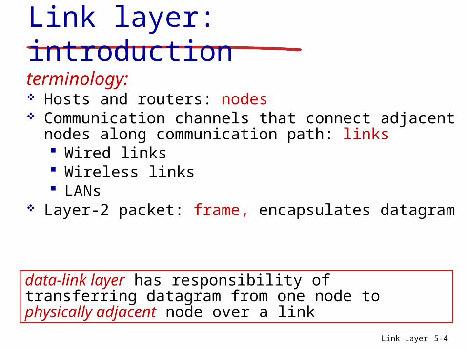
Link layer introductionterminology Hosts and routers nodes Communication channels that connect adjacent
nodes along communication path links Wired links Wireless links LANs
Layer-2 packet frame encapsulates datagram
data-link layer has responsibility of transferring datagram from one node to physically adjacent node over a link
Link Layer 5-5
Link layer introduction
global ISP
Link Layer 5-6
Link layer context
Datagrams transferred by different link protocols over different links Ex
Ethernet on first link Frame relay on intermediate links 80211 on last link
Each link protocol provides different services May or may not provide rdt over link
Ex 80211 Wi-Fi ndash very noisy provides forward error correction (FEC)
Link Layer 5-7
Link layer context
Transportation analogy Trip from Bowling Green to San Francisco
Limo Bowling Green to Nashville Airport Plane Nashville Airport to Las Vegas Bicycle Las Vegas to San Francisco
Tourist = datagram Transport segment = communication link Transportation mode = link layer protocol Travel agent = routing algorithm
Link Layer 5-8
Link layer services Framing
Encapsulate datagram into frame adding header trailer
Frame structure is specified by the link layer protocol Different frame structures protocols between
sourcedestination Link access
Channel access if shared medium ldquoMACrdquo addresses used in frame headers to identify
source dest bull Different from IP address
Reliable delivery between adjacent nodes We learned how to do this already (chapter 3) Seldom used on low bit-error link (fiber some twisted
pair) Wireless links high error rates
bull Q Why both link-level and end-end reliability
Link Layer 5-9
Flow control Pacing between adjacent sending and receiving nodes Reduces buffer overflow between nodes Similar to TCPrsquos flow control
Error detection Errors caused by signal attenuation noise Receiver detects presence of errors
bull Signals sender (previous node) for retransmission or drops frame
Error correction Receiver identifies and corrects bit error(s) without resorting to
retransmission Forward Error Correction
Half-duplex and full-duplex Half duplex Both nodes can transmit but not at the same time Full duplex Both nodes can transmit at the same time
Link layer services (more)
Link Layer 5-10
Many services provided by the link layer have strong parallels with services provided by the transport layer Both can provide reliable delivery
bull Transport layer reliable delivery between two end-to-end processes
bull Link layer reliable delivery between two nodes connected by a single link
Both can provide flow control and error detectionbull Transport layer flow controlerror detection between
processesbull Link layer flow controlerror detection between two nodes
Link layer services (more)
Link Layer 5-11
Where is the link layer implemented
In each and every host Link layer implemented in ldquoadaptorrdquo (aka network
interface card NIC) or on a chip Ethernet card 80211 card Ethernet chipset
bull Mostly embedded now Implements link physical layer
Attaches into hostrsquos system buses Combination of hardware software firmware
Link Layer 5-12
Where is the link layer implemented
controller
physicaltransmission
cpu memory
host bus (eg PCI)
network adaptercard
applicationtransportnetwork
link
linkphysical
Link Layer 5-13
Adaptors communicating
Sending side Encapsulates
datagram in frame Adds error checking
bits rdt flow control etc
Receiving side Looks for errors rdt
flow control etc Extracts datagram
passes to upper layer at receiving side
controller controller
sending host receiving host
datagram datagram
datagram
frame
Link Layer 5-14
Link layer LANs outline
51 introduction services
52 error detection correction
53 multiple access protocols
54 LANs addressing ARP Ethernet switches VLANS
55 link virtualization MPLS
56 data center networking
57 a day in the life of a web request
Link Layer 5-15
Error detection Bit-level error detection and correction
Between nodes connected by single link Frames with errors handled two ways
bull Receiving node (tries) to correct the errorbull Receiving node drops the frame
Link Layer 5-16
Error detectionbull EDC
bull Error Detection and Correction bitsbull D
bull Data protected by error checking may include header fieldsbull Error detection not 100 reliablebull Protocol may miss some errors but rarelybull Larger EDC field yields better detection and correction
bull Also reduces link throughput
otherwise
Error Detection and Correction
Bits are occasionally flipped in transmission For example 1101001 is sent but 0101011 is received
Adding redundancy can allow for detection and possibly correction of some errors
Simple approach Repeat each bit Repeat each bit twice For bit y transmit yy If the receiver
gets two different bits it requests a retransmissionbull This is an error detecting code
ndash Allows for one error to be detected but is not error correcting since retransmission is necessary
Repeat each bit three times For each bit y transmit yyybull Now the receiver can (most likely) correct a single error
ndash Why
Problem with the simple approach
The receiver can detect and correct bit errors if each bit is transmitted three times How does this affect performance
Better approach Parity check codes
bull Has the ability to detect odd number of bit flips using a single parity bit
Calculating bit string parity A bit string has odd parity if the
number of 1s in the string is odd 100011 1 000010 have odd parity
A bit string has even parity if the number if 1s in the string is even 01100 000 11001001 have even parity
Assume 0 is an even number
Parity check code Assume we are transmitting blocks of k bits
A block (w) of length (k) is encoded as (wa) where the value of the parity bit (a) is chosen so that (wa) has even parity
Example If w = 10110 we send wa = 101101 which has even parity
With no bit flips in the transmission the receiver gets the bit string exactly as it was sent by the sender Bit string has even parity
If there are an odd number of bit flips in the transmission the receiver gets a bit string with odd parity Retransmission is requested
If there are an even number of bit flips in the transmission the receiver gets a bit string with even parity The error(s) go undetected
Another solution
2D parity check code Blocks of bits are organized in rows and
columns m x n matrix The parity bit of each row is calculated and
appended to the row before it is transmitted The parity of each column is calculated and the
parity bit of the entire matrix is computedbull These are also transmitted to the receiver
m + n + 1 parity bits are computed mn + m + n + 1 bits are sent to the receiver
bull Efficiency becomes greater as block size increases
2D parity check
Example Original data 1100 1011 0111 0101
Row Parity
Column Parity Matrix Parity bit
MN + M + N + 1 bits transferred 55 + 5 + 5 + 1 = 36 bits
1 1 0 0 0
1 0 1 1 1
0 1 1 1 1
0 1 0 1 0
0 1 0 1 0
2D parity check
Another Example Original data 1101 1001 1111 0001 Calculate the Row Column and Matrix parity
Row Parity
Column Parity Matrix Parity bit
1 1 0 1
1 0 0 1
1 1 1 1
0 0 0 1
2D parity check
Another Example Received data 1101 1001 1111 0001 Calculate the Row Column and Matrix parity
Row Parity
Column Parity Matrix Parity bit
Possible to fix the problem without retransmitting the data
1 1 0 1 1
1 0 1 1 0
1 1 1 1 0
0 0 0 1 1
1 0 1 0 0
2D parity check
Another Example Received data 1101 1001 1111 0001 Calculate the Row Column and Matrix parity
Row Parity
Column Parity Matrix Parity bit
1 1 0 1 1
1 0 1 1 0
1 1 1 1 0
0 0 0 1 1
1 0 1 0 0
2D parity check
Another Example Received data 1101 1001 1111 0001 Calculate the Row Column and Matrix parity
Row Parity
Column Parity Matrix Parity bit
1 1 0 1 1
1 0 0 1 0
1 1 1 1 0
0 0 0 1 1
1 0 1 0 0
2D parity check
2D parity check can detect and correct all 1 bit errors
Error bit
0 1 1 0 1 0 0 1
1 0 1 1 0 1 0 0
0 0 0 0 1 1 0 1
1 1 1 0 1 0 1 1
1 0 0 1 0 1 1 0
1 0 0 0 1 1 0 1
2D parity check
2D parity check can detect all 2 bit errors Canrsquot correct all 2 bit errors Data must be
resent
Error bits
0 1 1 0 1 0 0 1
1 0 1 1 0 1 0 0
0 0 0 0 1 1 1 1
1 1 1 0 1 0 1 1
1 0 0 1 0 1 1 0
1 0 0 0 1 1 0 1
2D parity check
2D parity check can detect all 3 bit errors Canrsquot correct all 3 bit errors Data must be
resent
Error bits
0 1 1 0 1 0 0 1
1 0 1 1 0 1 0 0
0 0 0 0 1 1 1 1
1 1 0 0 1 0 1 1
1 0 0 1 0 1 1 0
1 0 0 0 1 1 0 1
2D parity check
2D parity check can detect most 4 bit errors Canrsquot correct all 4 bit errors Data must be
resent Example of a 4 bit error that is NOT
detected
Error bits
0 1 1 0 1 0 0 1
1 0 1 1 0 1 0 0
0 0 0 0 1 1 1 1
1 1 0 0 1 0 0 1
1 0 0 1 0 1 1 0
1 0 0 0 1 1 0 1
Link Layer 5-31
Internet checksum (review)
sender treat segment
contents as sequence of 16-bit integers
checksum addition (1rsquos complement sum) of segment contents
sender puts checksum value into UDP checksum field
receiver compute checksum of
received segment check if computed
checksum equals checksum field value NO - error detected YES - no error
detected But maybe errors nonetheless
goal detect ldquoerrorsrdquo (eg flipped bits) in transmitted packet (note used at transport layer only)
Link Layer 5-32
Cyclic redundancy check more powerful error-detection coding view data bits D as a binary number choose r+1 bit pattern (generator) G goal choose r CRC bits R such that
ltDRgt exactly divisible by G (modulo 2) receiver knows G divides ltDRgt by G If non-zero
remainder error detected can detect all burst errors less than r+1 bits
widely used in practice (Ethernet 80211 WiFi ATM)
Link Layer 5-33
Link layer LANs outline
51 introduction services
52 error detection correction
53 multiple access protocols
54 LANs addressing ARP Ethernet switches VLANS
55 link virtualization MPLS
56 data center networking
57 a day in the life of a web request
Link Layer 5-34
Multiple access links protocols
Two types of ldquolinksrdquo Point-to-point
PPP for dial-up access Point-to-point link between Ethernet switch host
Broadcast (shared wire or medium) Old-fashioned Ethernet Upstream HFC 80211 wireless LAN
shared wire (eg cabled Ethernet)
shared RF (eg 80211 WiFi)
shared RF(satellite)
humans at acocktail party
(shared air acoustical)
Link Layer 5-35
Multiple access protocols Single shared broadcast channel Two or more simultaneous transmissions by nodes
interference Collision if node receives two or more signals at the
same time
Multiple access protocol Distributed algorithm that determines how nodes share
channel ie determine when node can transmit Communication about channel sharing must use
channel itself No out-of-band channel for coordination
Link Layer 5-36
An ideal multiple access protocol
Given broadcast channel of rate R bps Desirable characteristics
1 When one node wants to transmit it can send at rate R2 When M nodes want to transmit each can send at average rate RM3 Fully decentralizedbull No special node to coordinate transmissionsbull No synchronization of clocks slots
4 Simple
Link Layer 5-37
MAC protocols taxonomy
Three broad classes Channel partitioning
Divide channel into smaller ldquopiecesrdquo (time slots frequency code)
Allocate piece to node for exclusive use FDMA TDMA CDMA
Random access Channel not divided allow collisions ldquoRecoverrdquo from collisions Ethernet
ldquoTaking turnsrdquo Nodes take turns but nodes with more to send can take longer
turns Token ring
Link Layer 5-38
Channel partitioning MAC protocols TDMA
TDMA time division multiple access Access to channel in rounds Each station gets fixed length slot (length = pkt
trans time) in each round Unused slots go idle Example
6-station LAN 134 have pkt slots 256 idle
1 3 4 1 3 4
6-slotframe
6-slotframe
Link Layer 5-39
FDMA frequency division multiple access Channel spectrum divided into frequency bands Each station assigned fixed frequency band Unused transmission time in frequency bands
go idle Example
6-station LAN 134 have pkt frequency bands 256 idle
freq
uenc
y ba
nds
time
FDM cable
Channel partitioning MAC protocols FDMA
Link Layer 5-40
Random access protocols When node has packet to send
Transmit at full channel data rate R No coordination among nodes
Two or more transmitting nodes ldquocollisionrdquo Random access MAC protocol specifies
How to detect collisions How to recover from collisions (eg via delayed
retransmissions) Examples of random access MAC protocols
ALOHA Slotted ALOHA CSMA CSMACD CSMACA
Link Layer 5-41
ALOHA
Aloha Norm Abramson (1969-1970) First radio packet network connecting the
Hawaiian Islands Two channels (different frequencies)
bull Downlink transmission from central host to secondary hosts
bull Uplink transmission from secondary host to central host
Important communication protocolbull First radio packet network decades before Wi-Fi
WiMAX Cellularbull Inspired CSMACD protocol used extensively by
8023 Ethernet
Link Layer 5-42
ALOHA Aloha simple no synchronization When frame first arrives
Transmit immediately High collision probability with multiple nodes
transmitting frame sent at t0 collides with other frames sent
in [t0-1t0+1]
Link Layer 5-43
ALOHA efficiencyP(success by given node) = P(node transmits)
P(no other node transmits in [t0-1t0]
P(no other node transmits in [t0-1t0]
= p (1-p)N-1 (1-p)N-1
= p (1-p)2(N-1)
hellip choosing optimum p and then letting n
= 1(2e) = 18
ALOHA bandwidth efficiency only 18Ex 18 Mbps max throughput over 100 Mbps link with multiple nodes
Link Layer 5-44
Slotted ALOHA
Assumptions all frames same size Time divided into equal size slots (time to transmit 1
frame) Nodes transmit only at the beginning of each slot Nodes are synchronized for slot timing not frame
transmission If 2 or more nodes transmit in slot all nodes detect
collision
Link Layer 5-45
Slotted ALOHA
Operation When node obtains fresh frame transmits in next slot
If no collision node can send new frame in next slot If collision node retransmits frame in each
subsequent slot with probability p until success
Link Layer 5-46
Pros single active node can
continuously transmit at full rate of channel
highly decentralized only slots in nodes need to be in sync
simple
Cons collisions wasting slots idle slots nodes may be able to
detect collision in less than time to transmit packet
clock synchronization
Slotted ALOHA1 1 1 1
2
3
2 2
3 3
node 1
node 2
node 3
C C CS S SE E E
Link Layer 5-47
Suppose N nodes with many frames to send each transmits in slot with probability p
Prob that given node has success in a slot = p(1-p)N-1
Prob that any node has a success = Np(1-p)N-1
Max efficiency find p that maximizes Np(1-p)N-1
For many nodes take limit of Np(1-p)N-1 as N goes to infinity gives
Max efficiency = 1e = 37
Efficiency long-run fraction of successful slots (many nodes all with many frames to send)
Best channel used for useful transmissions 37 of time
Better than unslotted ALOHA
Slotted ALOHA efficiency
Link Layer 5-48
CSMA (carrier sense multiple access)
CSMA listen before transmit If channel sensed is idle
Transmit entire frame If channel sensed is busy
Defer transmission
Human analogy donrsquot interrupt others
Link Layer 5-49
CSMA collisions Collisions can still occur
Propagation delay means two nodes may not hear each otherrsquos transmission
Collision Entire packet
transmission time wasted Distance amp propagation
delay play role in in determining collision probability
spatial layout of nodes
Link Layer 5-50
CSMACD (collision detection)
CSMACD Carrier Sense Multiple AccessCollision Detection Collisions detected within short time Colliding transmissions aborted reducing channel
wastage
Collision detection Easy in wired LANs measure signal strengths
compare transmitted received signals Difficult in wireless LANs received signal strength
overwhelmed by local transmission strength
Link Layer 5-51
CSMACD (collision detection)
spatial layout of nodes
Link Layer 5-52
Ethernet CSMACD algorithm1 NIC receives datagram from network layer creates
frame
2 If NIC senses channel idle starts frame transmission If NIC senses channel busy waits until channel idle then transmits
3 If NIC transmits entire frame without detecting another transmission NIC is done with frame
4 If NIC detects another transmission while transmitting aborts and sends jam signal
5 After aborting NIC enters binary (exponential) backoff state After mth collision NIC chooses K at random from 012 hellip
2m-1 NIC waits K512 bit times returns to Step 2 longer backoff intervals with more collisions
Link Layer 5-53
CSMACD efficiency
Tprop = max prop delay between 2 nodes in LAN ttrans = time to transmit max-size frame
Efficiency goes to 1 as tprop goes to 0 as ttrans goes to infinity
Better performance than ALOHA Also simple cheap and decentralized
transprop ttefficiency
51
1
Link Layer 5-54
ldquoTaking turnsrdquo MAC protocols
Channel partitioning MAC protocols Share channel efficiently and fairly at high
load Inefficient at low load delay in channel
access 1N bandwidth allocated even if only 1 active node
Random access MAC protocols Efficient at low load single node can fully
utilize channel High load collision overhead
ldquoTaking turnsrdquo protocols Look for best of both worlds
Link Layer 5-55
Polling Master node ldquoinvitesrdquo slave
nodes to transmit in turn Typically used with ldquodumbrdquo
slave devices Concerns
bull Polling overhead bull Latencybull Single point of failure
(master)
master
slaves
poll
data
data
ldquoTaking turnsrdquo MAC protocols
Link Layer 5-56
Token passing Control token passed from
one node to next sequentially Token message Concerns
Token overhead Latency Single point of failure
(token)
T
data
(nothingto send)
T
ldquoTaking turnsrdquo MAC protocols
cable headend
CMTS
ISP
cable modemtermination system
Multiple downstream (broadcast) channels Multiple upstream channels Multiple access all users contend for certain upstream
channel time slots (others assigned)
Cable access network
cablemodem
splitter
hellip
hellip
Internet framesTV channels control transmitted downstream at different frequencies
upstream Internet frames TV control transmitted upstream at different frequencies in time slots
Link Layer 5-58
Summary of MAC protocols
Channel partitioning By time frequency or code Time Division Frequency Division
Random access (dynamic) ALOHA S-ALOHA CSMA CSMACD Carrier sensing
Easy in some technologies (wire) hard in others (wireless) CSMACD used in Ethernet CSMACA used in 80211
Taking turns Polling from central site token passing Bluetooth FDDI token ring
- Slide 1
- Chapter 5 Link layer
- Link layer LANs outline
- Link layer introduction
- Link layer introduction (2)
- Link layer context
- Link layer context (2)
- Link layer services
- Link layer services (more)
- Link layer services (more) (2)
- Where is the link layer implemented
- Where is the link layer implemented (2)
- Adaptors communicating
- Link layer LANs outline (2)
- Error detection
- Error detection (2)
- Error Detection and Correction
- Problem with the simple approach
- Calculating bit string parity
- Parity check code
- 2D parity check code
- 2D parity check
- 2D parity check (2)
- 2D parity check (3)
- 2D parity check (4)
- 2D parity check (5)
- 2D parity check (6)
- 2D parity check (7)
- 2D parity check (8)
- 2D parity check (9)
- Internet checksum (review)
- Cyclic redundancy check
- Link layer LANs outline (3)
- Multiple access links protocols
- Multiple access protocols
- An ideal multiple access protocol
- MAC protocols taxonomy
- Channel partitioning MAC protocols TDMA
- Channel partitioning MAC protocols FDMA
- Random access protocols
- ALOHA
- ALOHA (2)
- ALOHA efficiency
- Slotted ALOHA
- Slotted ALOHA (2)
- Slotted ALOHA (3)
- Slotted ALOHA efficiency
- CSMA (carrier sense multiple access)
- CSMA collisions
- CSMACD (collision detection)
- CSMACD (collision detection) (2)
- Ethernet CSMACD algorithm
- CSMACD efficiency
- ldquoTaking turnsrdquo MAC protocols
- ldquoTaking turnsrdquo MAC protocols (2)
- ldquoTaking turnsrdquo MAC protocols (3)
- Slide 57
- Summary of MAC protocols
-

Link Layer 5-2
Chapter 5 Link layerGoals Understand principles behind link layer
services Error detection correction Sharing a broadcast channel multiple access Link layer addressing Local area networks Ethernet VLANs
Instantiation implementation of various link layer technologies
Transport Layer Logical process to process communication
Network Layer Host to Host communication though intermediate routers
Link Layer Node to Node communication over a single path
Link Layer 5-3
Link layer LANs outline
51 introduction services
52 error detection correction
53 multiple access protocols
54 LANs addressing ARP Ethernet switches VLANS
55 link virtualization MPLS
56 data center networking
57 a day in the life of a web request
Link Layer 5-4
Link layer introductionterminology Hosts and routers nodes Communication channels that connect adjacent
nodes along communication path links Wired links Wireless links LANs
Layer-2 packet frame encapsulates datagram
data-link layer has responsibility of transferring datagram from one node to physically adjacent node over a link
Link Layer 5-5
Link layer introduction
global ISP
Link Layer 5-6
Link layer context
Datagrams transferred by different link protocols over different links Ex
Ethernet on first link Frame relay on intermediate links 80211 on last link
Each link protocol provides different services May or may not provide rdt over link
Ex 80211 Wi-Fi ndash very noisy provides forward error correction (FEC)
Link Layer 5-7
Link layer context
Transportation analogy Trip from Bowling Green to San Francisco
Limo Bowling Green to Nashville Airport Plane Nashville Airport to Las Vegas Bicycle Las Vegas to San Francisco
Tourist = datagram Transport segment = communication link Transportation mode = link layer protocol Travel agent = routing algorithm
Link Layer 5-8
Link layer services Framing
Encapsulate datagram into frame adding header trailer
Frame structure is specified by the link layer protocol Different frame structures protocols between
sourcedestination Link access
Channel access if shared medium ldquoMACrdquo addresses used in frame headers to identify
source dest bull Different from IP address
Reliable delivery between adjacent nodes We learned how to do this already (chapter 3) Seldom used on low bit-error link (fiber some twisted
pair) Wireless links high error rates
bull Q Why both link-level and end-end reliability
Link Layer 5-9
Flow control Pacing between adjacent sending and receiving nodes Reduces buffer overflow between nodes Similar to TCPrsquos flow control
Error detection Errors caused by signal attenuation noise Receiver detects presence of errors
bull Signals sender (previous node) for retransmission or drops frame
Error correction Receiver identifies and corrects bit error(s) without resorting to
retransmission Forward Error Correction
Half-duplex and full-duplex Half duplex Both nodes can transmit but not at the same time Full duplex Both nodes can transmit at the same time
Link layer services (more)
Link Layer 5-10
Many services provided by the link layer have strong parallels with services provided by the transport layer Both can provide reliable delivery
bull Transport layer reliable delivery between two end-to-end processes
bull Link layer reliable delivery between two nodes connected by a single link
Both can provide flow control and error detectionbull Transport layer flow controlerror detection between
processesbull Link layer flow controlerror detection between two nodes
Link layer services (more)
Link Layer 5-11
Where is the link layer implemented
In each and every host Link layer implemented in ldquoadaptorrdquo (aka network
interface card NIC) or on a chip Ethernet card 80211 card Ethernet chipset
bull Mostly embedded now Implements link physical layer
Attaches into hostrsquos system buses Combination of hardware software firmware
Link Layer 5-12
Where is the link layer implemented
controller
physicaltransmission
cpu memory
host bus (eg PCI)
network adaptercard
applicationtransportnetwork
link
linkphysical
Link Layer 5-13
Adaptors communicating
Sending side Encapsulates
datagram in frame Adds error checking
bits rdt flow control etc
Receiving side Looks for errors rdt
flow control etc Extracts datagram
passes to upper layer at receiving side
controller controller
sending host receiving host
datagram datagram
datagram
frame
Link Layer 5-14
Link layer LANs outline
51 introduction services
52 error detection correction
53 multiple access protocols
54 LANs addressing ARP Ethernet switches VLANS
55 link virtualization MPLS
56 data center networking
57 a day in the life of a web request
Link Layer 5-15
Error detection Bit-level error detection and correction
Between nodes connected by single link Frames with errors handled two ways
bull Receiving node (tries) to correct the errorbull Receiving node drops the frame
Link Layer 5-16
Error detectionbull EDC
bull Error Detection and Correction bitsbull D
bull Data protected by error checking may include header fieldsbull Error detection not 100 reliablebull Protocol may miss some errors but rarelybull Larger EDC field yields better detection and correction
bull Also reduces link throughput
otherwise
Error Detection and Correction
Bits are occasionally flipped in transmission For example 1101001 is sent but 0101011 is received
Adding redundancy can allow for detection and possibly correction of some errors
Simple approach Repeat each bit Repeat each bit twice For bit y transmit yy If the receiver
gets two different bits it requests a retransmissionbull This is an error detecting code
ndash Allows for one error to be detected but is not error correcting since retransmission is necessary
Repeat each bit three times For each bit y transmit yyybull Now the receiver can (most likely) correct a single error
ndash Why
Problem with the simple approach
The receiver can detect and correct bit errors if each bit is transmitted three times How does this affect performance
Better approach Parity check codes
bull Has the ability to detect odd number of bit flips using a single parity bit
Calculating bit string parity A bit string has odd parity if the
number of 1s in the string is odd 100011 1 000010 have odd parity
A bit string has even parity if the number if 1s in the string is even 01100 000 11001001 have even parity
Assume 0 is an even number
Parity check code Assume we are transmitting blocks of k bits
A block (w) of length (k) is encoded as (wa) where the value of the parity bit (a) is chosen so that (wa) has even parity
Example If w = 10110 we send wa = 101101 which has even parity
With no bit flips in the transmission the receiver gets the bit string exactly as it was sent by the sender Bit string has even parity
If there are an odd number of bit flips in the transmission the receiver gets a bit string with odd parity Retransmission is requested
If there are an even number of bit flips in the transmission the receiver gets a bit string with even parity The error(s) go undetected
Another solution
2D parity check code Blocks of bits are organized in rows and
columns m x n matrix The parity bit of each row is calculated and
appended to the row before it is transmitted The parity of each column is calculated and the
parity bit of the entire matrix is computedbull These are also transmitted to the receiver
m + n + 1 parity bits are computed mn + m + n + 1 bits are sent to the receiver
bull Efficiency becomes greater as block size increases
2D parity check
Example Original data 1100 1011 0111 0101
Row Parity
Column Parity Matrix Parity bit
MN + M + N + 1 bits transferred 55 + 5 + 5 + 1 = 36 bits
1 1 0 0 0
1 0 1 1 1
0 1 1 1 1
0 1 0 1 0
0 1 0 1 0
2D parity check
Another Example Original data 1101 1001 1111 0001 Calculate the Row Column and Matrix parity
Row Parity
Column Parity Matrix Parity bit
1 1 0 1
1 0 0 1
1 1 1 1
0 0 0 1
2D parity check
Another Example Received data 1101 1001 1111 0001 Calculate the Row Column and Matrix parity
Row Parity
Column Parity Matrix Parity bit
Possible to fix the problem without retransmitting the data
1 1 0 1 1
1 0 1 1 0
1 1 1 1 0
0 0 0 1 1
1 0 1 0 0
2D parity check
Another Example Received data 1101 1001 1111 0001 Calculate the Row Column and Matrix parity
Row Parity
Column Parity Matrix Parity bit
1 1 0 1 1
1 0 1 1 0
1 1 1 1 0
0 0 0 1 1
1 0 1 0 0
2D parity check
Another Example Received data 1101 1001 1111 0001 Calculate the Row Column and Matrix parity
Row Parity
Column Parity Matrix Parity bit
1 1 0 1 1
1 0 0 1 0
1 1 1 1 0
0 0 0 1 1
1 0 1 0 0
2D parity check
2D parity check can detect and correct all 1 bit errors
Error bit
0 1 1 0 1 0 0 1
1 0 1 1 0 1 0 0
0 0 0 0 1 1 0 1
1 1 1 0 1 0 1 1
1 0 0 1 0 1 1 0
1 0 0 0 1 1 0 1
2D parity check
2D parity check can detect all 2 bit errors Canrsquot correct all 2 bit errors Data must be
resent
Error bits
0 1 1 0 1 0 0 1
1 0 1 1 0 1 0 0
0 0 0 0 1 1 1 1
1 1 1 0 1 0 1 1
1 0 0 1 0 1 1 0
1 0 0 0 1 1 0 1
2D parity check
2D parity check can detect all 3 bit errors Canrsquot correct all 3 bit errors Data must be
resent
Error bits
0 1 1 0 1 0 0 1
1 0 1 1 0 1 0 0
0 0 0 0 1 1 1 1
1 1 0 0 1 0 1 1
1 0 0 1 0 1 1 0
1 0 0 0 1 1 0 1
2D parity check
2D parity check can detect most 4 bit errors Canrsquot correct all 4 bit errors Data must be
resent Example of a 4 bit error that is NOT
detected
Error bits
0 1 1 0 1 0 0 1
1 0 1 1 0 1 0 0
0 0 0 0 1 1 1 1
1 1 0 0 1 0 0 1
1 0 0 1 0 1 1 0
1 0 0 0 1 1 0 1
Link Layer 5-31
Internet checksum (review)
sender treat segment
contents as sequence of 16-bit integers
checksum addition (1rsquos complement sum) of segment contents
sender puts checksum value into UDP checksum field
receiver compute checksum of
received segment check if computed
checksum equals checksum field value NO - error detected YES - no error
detected But maybe errors nonetheless
goal detect ldquoerrorsrdquo (eg flipped bits) in transmitted packet (note used at transport layer only)
Link Layer 5-32
Cyclic redundancy check more powerful error-detection coding view data bits D as a binary number choose r+1 bit pattern (generator) G goal choose r CRC bits R such that
ltDRgt exactly divisible by G (modulo 2) receiver knows G divides ltDRgt by G If non-zero
remainder error detected can detect all burst errors less than r+1 bits
widely used in practice (Ethernet 80211 WiFi ATM)
Link Layer 5-33
Link layer LANs outline
51 introduction services
52 error detection correction
53 multiple access protocols
54 LANs addressing ARP Ethernet switches VLANS
55 link virtualization MPLS
56 data center networking
57 a day in the life of a web request
Link Layer 5-34
Multiple access links protocols
Two types of ldquolinksrdquo Point-to-point
PPP for dial-up access Point-to-point link between Ethernet switch host
Broadcast (shared wire or medium) Old-fashioned Ethernet Upstream HFC 80211 wireless LAN
shared wire (eg cabled Ethernet)
shared RF (eg 80211 WiFi)
shared RF(satellite)
humans at acocktail party
(shared air acoustical)
Link Layer 5-35
Multiple access protocols Single shared broadcast channel Two or more simultaneous transmissions by nodes
interference Collision if node receives two or more signals at the
same time
Multiple access protocol Distributed algorithm that determines how nodes share
channel ie determine when node can transmit Communication about channel sharing must use
channel itself No out-of-band channel for coordination
Link Layer 5-36
An ideal multiple access protocol
Given broadcast channel of rate R bps Desirable characteristics
1 When one node wants to transmit it can send at rate R2 When M nodes want to transmit each can send at average rate RM3 Fully decentralizedbull No special node to coordinate transmissionsbull No synchronization of clocks slots
4 Simple
Link Layer 5-37
MAC protocols taxonomy
Three broad classes Channel partitioning
Divide channel into smaller ldquopiecesrdquo (time slots frequency code)
Allocate piece to node for exclusive use FDMA TDMA CDMA
Random access Channel not divided allow collisions ldquoRecoverrdquo from collisions Ethernet
ldquoTaking turnsrdquo Nodes take turns but nodes with more to send can take longer
turns Token ring
Link Layer 5-38
Channel partitioning MAC protocols TDMA
TDMA time division multiple access Access to channel in rounds Each station gets fixed length slot (length = pkt
trans time) in each round Unused slots go idle Example
6-station LAN 134 have pkt slots 256 idle
1 3 4 1 3 4
6-slotframe
6-slotframe
Link Layer 5-39
FDMA frequency division multiple access Channel spectrum divided into frequency bands Each station assigned fixed frequency band Unused transmission time in frequency bands
go idle Example
6-station LAN 134 have pkt frequency bands 256 idle
freq
uenc
y ba
nds
time
FDM cable
Channel partitioning MAC protocols FDMA
Link Layer 5-40
Random access protocols When node has packet to send
Transmit at full channel data rate R No coordination among nodes
Two or more transmitting nodes ldquocollisionrdquo Random access MAC protocol specifies
How to detect collisions How to recover from collisions (eg via delayed
retransmissions) Examples of random access MAC protocols
ALOHA Slotted ALOHA CSMA CSMACD CSMACA
Link Layer 5-41
ALOHA
Aloha Norm Abramson (1969-1970) First radio packet network connecting the
Hawaiian Islands Two channels (different frequencies)
bull Downlink transmission from central host to secondary hosts
bull Uplink transmission from secondary host to central host
Important communication protocolbull First radio packet network decades before Wi-Fi
WiMAX Cellularbull Inspired CSMACD protocol used extensively by
8023 Ethernet
Link Layer 5-42
ALOHA Aloha simple no synchronization When frame first arrives
Transmit immediately High collision probability with multiple nodes
transmitting frame sent at t0 collides with other frames sent
in [t0-1t0+1]
Link Layer 5-43
ALOHA efficiencyP(success by given node) = P(node transmits)
P(no other node transmits in [t0-1t0]
P(no other node transmits in [t0-1t0]
= p (1-p)N-1 (1-p)N-1
= p (1-p)2(N-1)
hellip choosing optimum p and then letting n
= 1(2e) = 18
ALOHA bandwidth efficiency only 18Ex 18 Mbps max throughput over 100 Mbps link with multiple nodes
Link Layer 5-44
Slotted ALOHA
Assumptions all frames same size Time divided into equal size slots (time to transmit 1
frame) Nodes transmit only at the beginning of each slot Nodes are synchronized for slot timing not frame
transmission If 2 or more nodes transmit in slot all nodes detect
collision
Link Layer 5-45
Slotted ALOHA
Operation When node obtains fresh frame transmits in next slot
If no collision node can send new frame in next slot If collision node retransmits frame in each
subsequent slot with probability p until success
Link Layer 5-46
Pros single active node can
continuously transmit at full rate of channel
highly decentralized only slots in nodes need to be in sync
simple
Cons collisions wasting slots idle slots nodes may be able to
detect collision in less than time to transmit packet
clock synchronization
Slotted ALOHA1 1 1 1
2
3
2 2
3 3
node 1
node 2
node 3
C C CS S SE E E
Link Layer 5-47
Suppose N nodes with many frames to send each transmits in slot with probability p
Prob that given node has success in a slot = p(1-p)N-1
Prob that any node has a success = Np(1-p)N-1
Max efficiency find p that maximizes Np(1-p)N-1
For many nodes take limit of Np(1-p)N-1 as N goes to infinity gives
Max efficiency = 1e = 37
Efficiency long-run fraction of successful slots (many nodes all with many frames to send)
Best channel used for useful transmissions 37 of time
Better than unslotted ALOHA
Slotted ALOHA efficiency
Link Layer 5-48
CSMA (carrier sense multiple access)
CSMA listen before transmit If channel sensed is idle
Transmit entire frame If channel sensed is busy
Defer transmission
Human analogy donrsquot interrupt others
Link Layer 5-49
CSMA collisions Collisions can still occur
Propagation delay means two nodes may not hear each otherrsquos transmission
Collision Entire packet
transmission time wasted Distance amp propagation
delay play role in in determining collision probability
spatial layout of nodes
Link Layer 5-50
CSMACD (collision detection)
CSMACD Carrier Sense Multiple AccessCollision Detection Collisions detected within short time Colliding transmissions aborted reducing channel
wastage
Collision detection Easy in wired LANs measure signal strengths
compare transmitted received signals Difficult in wireless LANs received signal strength
overwhelmed by local transmission strength
Link Layer 5-51
CSMACD (collision detection)
spatial layout of nodes
Link Layer 5-52
Ethernet CSMACD algorithm1 NIC receives datagram from network layer creates
frame
2 If NIC senses channel idle starts frame transmission If NIC senses channel busy waits until channel idle then transmits
3 If NIC transmits entire frame without detecting another transmission NIC is done with frame
4 If NIC detects another transmission while transmitting aborts and sends jam signal
5 After aborting NIC enters binary (exponential) backoff state After mth collision NIC chooses K at random from 012 hellip
2m-1 NIC waits K512 bit times returns to Step 2 longer backoff intervals with more collisions
Link Layer 5-53
CSMACD efficiency
Tprop = max prop delay between 2 nodes in LAN ttrans = time to transmit max-size frame
Efficiency goes to 1 as tprop goes to 0 as ttrans goes to infinity
Better performance than ALOHA Also simple cheap and decentralized
transprop ttefficiency
51
1
Link Layer 5-54
ldquoTaking turnsrdquo MAC protocols
Channel partitioning MAC protocols Share channel efficiently and fairly at high
load Inefficient at low load delay in channel
access 1N bandwidth allocated even if only 1 active node
Random access MAC protocols Efficient at low load single node can fully
utilize channel High load collision overhead
ldquoTaking turnsrdquo protocols Look for best of both worlds
Link Layer 5-55
Polling Master node ldquoinvitesrdquo slave
nodes to transmit in turn Typically used with ldquodumbrdquo
slave devices Concerns
bull Polling overhead bull Latencybull Single point of failure
(master)
master
slaves
poll
data
data
ldquoTaking turnsrdquo MAC protocols
Link Layer 5-56
Token passing Control token passed from
one node to next sequentially Token message Concerns
Token overhead Latency Single point of failure
(token)
T
data
(nothingto send)
T
ldquoTaking turnsrdquo MAC protocols
cable headend
CMTS
ISP
cable modemtermination system
Multiple downstream (broadcast) channels Multiple upstream channels Multiple access all users contend for certain upstream
channel time slots (others assigned)
Cable access network
cablemodem
splitter
hellip
hellip
Internet framesTV channels control transmitted downstream at different frequencies
upstream Internet frames TV control transmitted upstream at different frequencies in time slots
Link Layer 5-58
Summary of MAC protocols
Channel partitioning By time frequency or code Time Division Frequency Division
Random access (dynamic) ALOHA S-ALOHA CSMA CSMACD Carrier sensing
Easy in some technologies (wire) hard in others (wireless) CSMACD used in Ethernet CSMACA used in 80211
Taking turns Polling from central site token passing Bluetooth FDDI token ring
- Slide 1
- Chapter 5 Link layer
- Link layer LANs outline
- Link layer introduction
- Link layer introduction (2)
- Link layer context
- Link layer context (2)
- Link layer services
- Link layer services (more)
- Link layer services (more) (2)
- Where is the link layer implemented
- Where is the link layer implemented (2)
- Adaptors communicating
- Link layer LANs outline (2)
- Error detection
- Error detection (2)
- Error Detection and Correction
- Problem with the simple approach
- Calculating bit string parity
- Parity check code
- 2D parity check code
- 2D parity check
- 2D parity check (2)
- 2D parity check (3)
- 2D parity check (4)
- 2D parity check (5)
- 2D parity check (6)
- 2D parity check (7)
- 2D parity check (8)
- 2D parity check (9)
- Internet checksum (review)
- Cyclic redundancy check
- Link layer LANs outline (3)
- Multiple access links protocols
- Multiple access protocols
- An ideal multiple access protocol
- MAC protocols taxonomy
- Channel partitioning MAC protocols TDMA
- Channel partitioning MAC protocols FDMA
- Random access protocols
- ALOHA
- ALOHA (2)
- ALOHA efficiency
- Slotted ALOHA
- Slotted ALOHA (2)
- Slotted ALOHA (3)
- Slotted ALOHA efficiency
- CSMA (carrier sense multiple access)
- CSMA collisions
- CSMACD (collision detection)
- CSMACD (collision detection) (2)
- Ethernet CSMACD algorithm
- CSMACD efficiency
- ldquoTaking turnsrdquo MAC protocols
- ldquoTaking turnsrdquo MAC protocols (2)
- ldquoTaking turnsrdquo MAC protocols (3)
- Slide 57
- Summary of MAC protocols
-
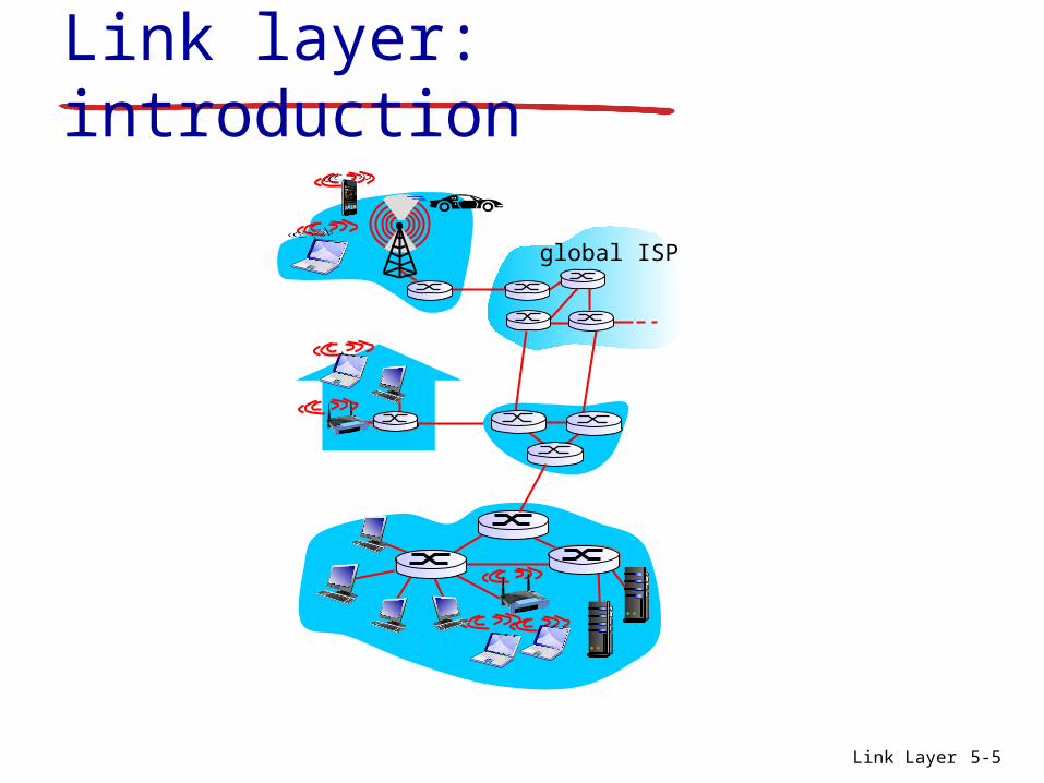
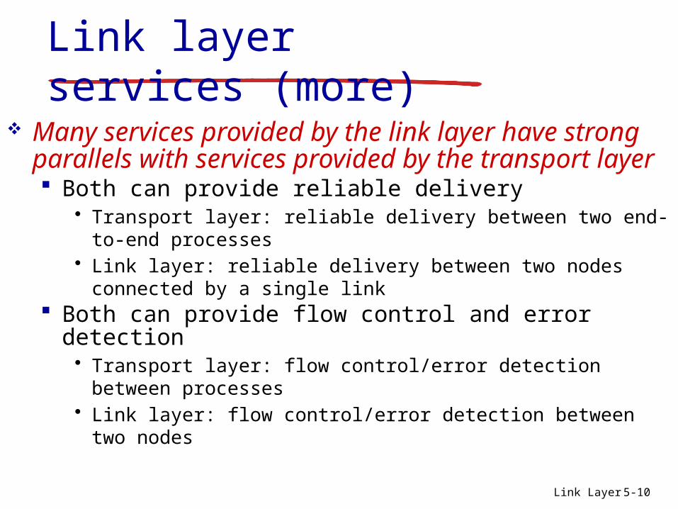
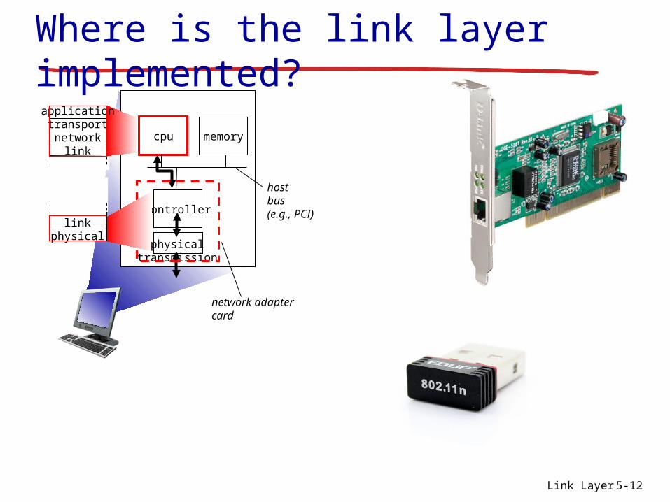
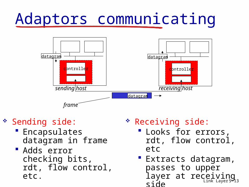
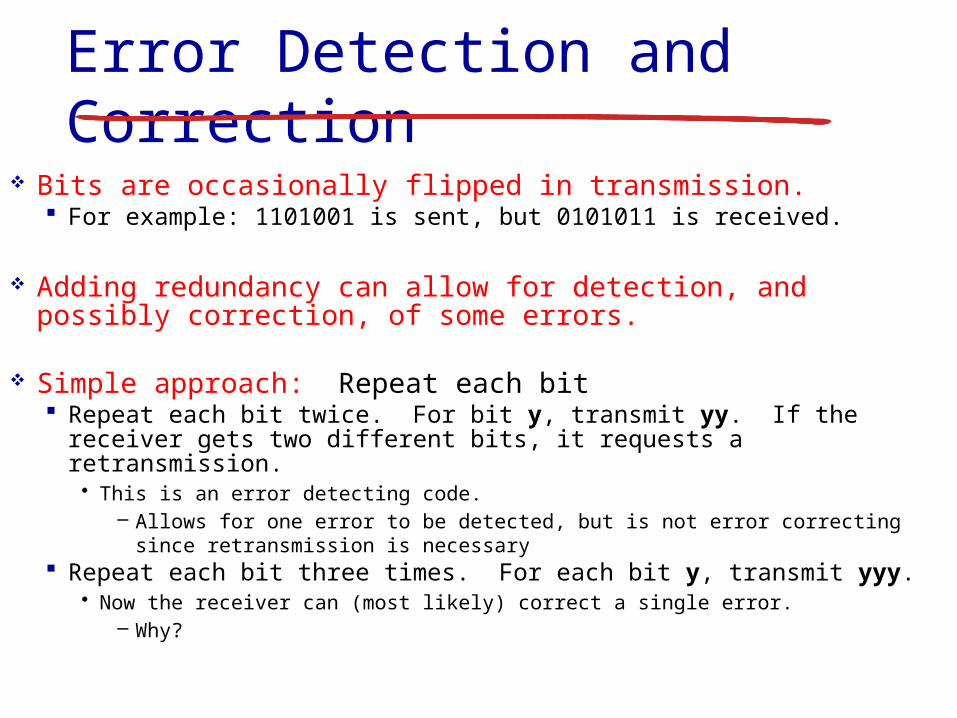
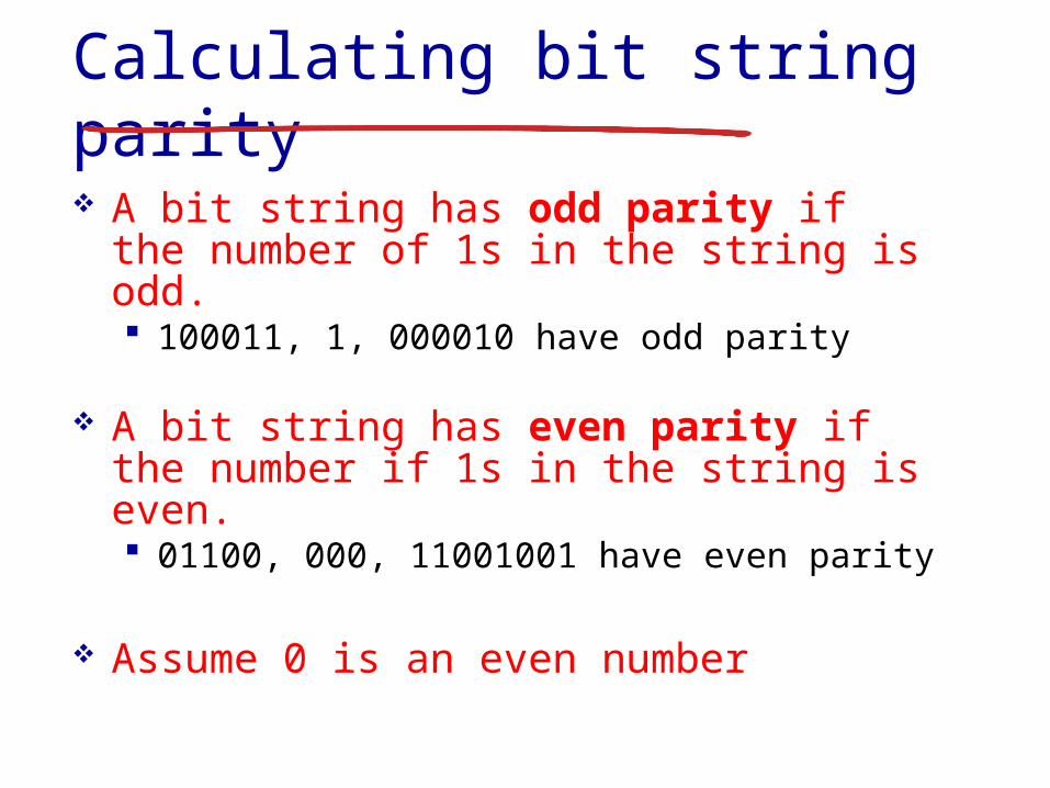
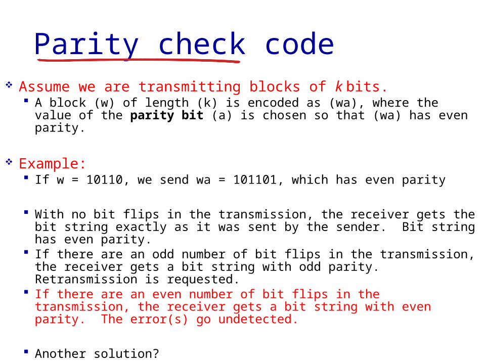
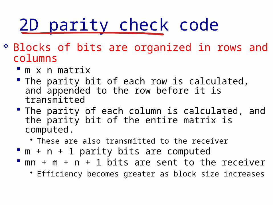

2D parity check
Example Original data 1100 1011 0111 0101
Row Parity
Column Parity Matrix Parity bit
MN + M + N + 1 bits transferred 55 + 5 + 5 + 1 = 36 bits
1 1 0 0 0
1 0 1 1 1
0 1 1 1 1
0 1 0 1 0
0 1 0 1 0
2D parity check
Another Example Original data 1101 1001 1111 0001 Calculate the Row Column and Matrix parity
Row Parity
Column Parity Matrix Parity bit
1 1 0 1
1 0 0 1
1 1 1 1
0 0 0 1
2D parity check
Another Example Received data 1101 1001 1111 0001 Calculate the Row Column and Matrix parity
Row Parity
Column Parity Matrix Parity bit
Possible to fix the problem without retransmitting the data
1 1 0 1 1
1 0 1 1 0
1 1 1 1 0
0 0 0 1 1
1 0 1 0 0
2D parity check
Another Example Received data 1101 1001 1111 0001 Calculate the Row Column and Matrix parity
Row Parity
Column Parity Matrix Parity bit
1 1 0 1 1
1 0 1 1 0
1 1 1 1 0
0 0 0 1 1
1 0 1 0 0
2D parity check
Another Example Received data 1101 1001 1111 0001 Calculate the Row Column and Matrix parity
Row Parity
Column Parity Matrix Parity bit
1 1 0 1 1
1 0 0 1 0
1 1 1 1 0
0 0 0 1 1
1 0 1 0 0
2D parity check
2D parity check can detect and correct all 1 bit errors
Error bit
0 1 1 0 1 0 0 1
1 0 1 1 0 1 0 0
0 0 0 0 1 1 0 1
1 1 1 0 1 0 1 1
1 0 0 1 0 1 1 0
1 0 0 0 1 1 0 1
2D parity check
2D parity check can detect all 2 bit errors Canrsquot correct all 2 bit errors Data must be
resent
Error bits
0 1 1 0 1 0 0 1
1 0 1 1 0 1 0 0
0 0 0 0 1 1 1 1
1 1 1 0 1 0 1 1
1 0 0 1 0 1 1 0
1 0 0 0 1 1 0 1
2D parity check
2D parity check can detect all 3 bit errors Canrsquot correct all 3 bit errors Data must be
resent
Error bits
0 1 1 0 1 0 0 1
1 0 1 1 0 1 0 0
0 0 0 0 1 1 1 1
1 1 0 0 1 0 1 1
1 0 0 1 0 1 1 0
1 0 0 0 1 1 0 1
2D parity check
2D parity check can detect most 4 bit errors Canrsquot correct all 4 bit errors Data must be
resent Example of a 4 bit error that is NOT
detected
Error bits
0 1 1 0 1 0 0 1
1 0 1 1 0 1 0 0
0 0 0 0 1 1 1 1
1 1 0 0 1 0 0 1
1 0 0 1 0 1 1 0
1 0 0 0 1 1 0 1
Link Layer 5-31
Internet checksum (review)
sender treat segment
contents as sequence of 16-bit integers
checksum addition (1rsquos complement sum) of segment contents
sender puts checksum value into UDP checksum field
receiver compute checksum of
received segment check if computed
checksum equals checksum field value NO - error detected YES - no error
detected But maybe errors nonetheless
goal detect ldquoerrorsrdquo (eg flipped bits) in transmitted packet (note used at transport layer only)
Link Layer 5-32
Cyclic redundancy check more powerful error-detection coding view data bits D as a binary number choose r+1 bit pattern (generator) G goal choose r CRC bits R such that
ltDRgt exactly divisible by G (modulo 2) receiver knows G divides ltDRgt by G If non-zero
remainder error detected can detect all burst errors less than r+1 bits
widely used in practice (Ethernet 80211 WiFi ATM)
Link Layer 5-33
Link layer LANs outline
51 introduction services
52 error detection correction
53 multiple access protocols
54 LANs addressing ARP Ethernet switches VLANS
55 link virtualization MPLS
56 data center networking
57 a day in the life of a web request
Link Layer 5-34
Multiple access links protocols
Two types of ldquolinksrdquo Point-to-point
PPP for dial-up access Point-to-point link between Ethernet switch host
Broadcast (shared wire or medium) Old-fashioned Ethernet Upstream HFC 80211 wireless LAN
shared wire (eg cabled Ethernet)
shared RF (eg 80211 WiFi)
shared RF(satellite)
humans at acocktail party
(shared air acoustical)
Link Layer 5-35
Multiple access protocols Single shared broadcast channel Two or more simultaneous transmissions by nodes
interference Collision if node receives two or more signals at the
same time
Multiple access protocol Distributed algorithm that determines how nodes share
channel ie determine when node can transmit Communication about channel sharing must use
channel itself No out-of-band channel for coordination
Link Layer 5-36
An ideal multiple access protocol
Given broadcast channel of rate R bps Desirable characteristics
1 When one node wants to transmit it can send at rate R2 When M nodes want to transmit each can send at average rate RM3 Fully decentralizedbull No special node to coordinate transmissionsbull No synchronization of clocks slots
4 Simple
Link Layer 5-37
MAC protocols taxonomy
Three broad classes Channel partitioning
Divide channel into smaller ldquopiecesrdquo (time slots frequency code)
Allocate piece to node for exclusive use FDMA TDMA CDMA
Random access Channel not divided allow collisions ldquoRecoverrdquo from collisions Ethernet
ldquoTaking turnsrdquo Nodes take turns but nodes with more to send can take longer
turns Token ring
Link Layer 5-38
Channel partitioning MAC protocols TDMA
TDMA time division multiple access Access to channel in rounds Each station gets fixed length slot (length = pkt
trans time) in each round Unused slots go idle Example
6-station LAN 134 have pkt slots 256 idle
1 3 4 1 3 4
6-slotframe
6-slotframe
Link Layer 5-39
FDMA frequency division multiple access Channel spectrum divided into frequency bands Each station assigned fixed frequency band Unused transmission time in frequency bands
go idle Example
6-station LAN 134 have pkt frequency bands 256 idle
freq
uenc
y ba
nds
time
FDM cable
Channel partitioning MAC protocols FDMA
Link Layer 5-40
Random access protocols When node has packet to send
Transmit at full channel data rate R No coordination among nodes
Two or more transmitting nodes ldquocollisionrdquo Random access MAC protocol specifies
How to detect collisions How to recover from collisions (eg via delayed
retransmissions) Examples of random access MAC protocols
ALOHA Slotted ALOHA CSMA CSMACD CSMACA
Link Layer 5-41
ALOHA
Aloha Norm Abramson (1969-1970) First radio packet network connecting the
Hawaiian Islands Two channels (different frequencies)
bull Downlink transmission from central host to secondary hosts
bull Uplink transmission from secondary host to central host
Important communication protocolbull First radio packet network decades before Wi-Fi
WiMAX Cellularbull Inspired CSMACD protocol used extensively by
8023 Ethernet
Link Layer 5-42
ALOHA Aloha simple no synchronization When frame first arrives
Transmit immediately High collision probability with multiple nodes
transmitting frame sent at t0 collides with other frames sent
in [t0-1t0+1]
Link Layer 5-43
ALOHA efficiencyP(success by given node) = P(node transmits)
P(no other node transmits in [t0-1t0]
P(no other node transmits in [t0-1t0]
= p (1-p)N-1 (1-p)N-1
= p (1-p)2(N-1)
hellip choosing optimum p and then letting n
= 1(2e) = 18
ALOHA bandwidth efficiency only 18Ex 18 Mbps max throughput over 100 Mbps link with multiple nodes
Link Layer 5-44
Slotted ALOHA
Assumptions all frames same size Time divided into equal size slots (time to transmit 1
frame) Nodes transmit only at the beginning of each slot Nodes are synchronized for slot timing not frame
transmission If 2 or more nodes transmit in slot all nodes detect
collision
Link Layer 5-45
Slotted ALOHA
Operation When node obtains fresh frame transmits in next slot
If no collision node can send new frame in next slot If collision node retransmits frame in each
subsequent slot with probability p until success
Link Layer 5-46
Pros single active node can
continuously transmit at full rate of channel
highly decentralized only slots in nodes need to be in sync
simple
Cons collisions wasting slots idle slots nodes may be able to
detect collision in less than time to transmit packet
clock synchronization
Slotted ALOHA1 1 1 1
2
3
2 2
3 3
node 1
node 2
node 3
C C CS S SE E E
Link Layer 5-47
Suppose N nodes with many frames to send each transmits in slot with probability p
Prob that given node has success in a slot = p(1-p)N-1
Prob that any node has a success = Np(1-p)N-1
Max efficiency find p that maximizes Np(1-p)N-1
For many nodes take limit of Np(1-p)N-1 as N goes to infinity gives
Max efficiency = 1e = 37
Efficiency long-run fraction of successful slots (many nodes all with many frames to send)
Best channel used for useful transmissions 37 of time
Better than unslotted ALOHA
Slotted ALOHA efficiency
Link Layer 5-48
CSMA (carrier sense multiple access)
CSMA listen before transmit If channel sensed is idle
Transmit entire frame If channel sensed is busy
Defer transmission
Human analogy donrsquot interrupt others
Link Layer 5-49
CSMA collisions Collisions can still occur
Propagation delay means two nodes may not hear each otherrsquos transmission
Collision Entire packet
transmission time wasted Distance amp propagation
delay play role in in determining collision probability
spatial layout of nodes
Link Layer 5-50
CSMACD (collision detection)
CSMACD Carrier Sense Multiple AccessCollision Detection Collisions detected within short time Colliding transmissions aborted reducing channel
wastage
Collision detection Easy in wired LANs measure signal strengths
compare transmitted received signals Difficult in wireless LANs received signal strength
overwhelmed by local transmission strength
Link Layer 5-51
CSMACD (collision detection)
spatial layout of nodes
Link Layer 5-52
Ethernet CSMACD algorithm1 NIC receives datagram from network layer creates
frame
2 If NIC senses channel idle starts frame transmission If NIC senses channel busy waits until channel idle then transmits
3 If NIC transmits entire frame without detecting another transmission NIC is done with frame
4 If NIC detects another transmission while transmitting aborts and sends jam signal
5 After aborting NIC enters binary (exponential) backoff state After mth collision NIC chooses K at random from 012 hellip
2m-1 NIC waits K512 bit times returns to Step 2 longer backoff intervals with more collisions
Link Layer 5-53
CSMACD efficiency
Tprop = max prop delay between 2 nodes in LAN ttrans = time to transmit max-size frame
Efficiency goes to 1 as tprop goes to 0 as ttrans goes to infinity
Better performance than ALOHA Also simple cheap and decentralized
transprop ttefficiency
51
1
Link Layer 5-54
ldquoTaking turnsrdquo MAC protocols
Channel partitioning MAC protocols Share channel efficiently and fairly at high
load Inefficient at low load delay in channel
access 1N bandwidth allocated even if only 1 active node
Random access MAC protocols Efficient at low load single node can fully
utilize channel High load collision overhead
ldquoTaking turnsrdquo protocols Look for best of both worlds
Link Layer 5-55
Polling Master node ldquoinvitesrdquo slave
nodes to transmit in turn Typically used with ldquodumbrdquo
slave devices Concerns
bull Polling overhead bull Latencybull Single point of failure
(master)
master
slaves
poll
data
data
ldquoTaking turnsrdquo MAC protocols
Link Layer 5-56
Token passing Control token passed from
one node to next sequentially Token message Concerns
Token overhead Latency Single point of failure
(token)
T
data
(nothingto send)
T
ldquoTaking turnsrdquo MAC protocols
cable headend
CMTS
ISP
cable modemtermination system
Multiple downstream (broadcast) channels Multiple upstream channels Multiple access all users contend for certain upstream
channel time slots (others assigned)
Cable access network
cablemodem
splitter
hellip
hellip
Internet framesTV channels control transmitted downstream at different frequencies
upstream Internet frames TV control transmitted upstream at different frequencies in time slots
Link Layer 5-58
Summary of MAC protocols
Channel partitioning By time frequency or code Time Division Frequency Division
Random access (dynamic) ALOHA S-ALOHA CSMA CSMACD Carrier sensing
Easy in some technologies (wire) hard in others (wireless) CSMACD used in Ethernet CSMACA used in 80211
Taking turns Polling from central site token passing Bluetooth FDDI token ring
- Slide 1
- Chapter 5 Link layer
- Link layer LANs outline
- Link layer introduction
- Link layer introduction (2)
- Link layer context
- Link layer context (2)
- Link layer services
- Link layer services (more)
- Link layer services (more) (2)
- Where is the link layer implemented
- Where is the link layer implemented (2)
- Adaptors communicating
- Link layer LANs outline (2)
- Error detection
- Error detection (2)
- Error Detection and Correction
- Problem with the simple approach
- Calculating bit string parity
- Parity check code
- 2D parity check code
- 2D parity check
- 2D parity check (2)
- 2D parity check (3)
- 2D parity check (4)
- 2D parity check (5)
- 2D parity check (6)
- 2D parity check (7)
- 2D parity check (8)
- 2D parity check (9)
- Internet checksum (review)
- Cyclic redundancy check
- Link layer LANs outline (3)
- Multiple access links protocols
- Multiple access protocols
- An ideal multiple access protocol
- MAC protocols taxonomy
- Channel partitioning MAC protocols TDMA
- Channel partitioning MAC protocols FDMA
- Random access protocols
- ALOHA
- ALOHA (2)
- ALOHA efficiency
- Slotted ALOHA
- Slotted ALOHA (2)
- Slotted ALOHA (3)
- Slotted ALOHA efficiency
- CSMA (carrier sense multiple access)
- CSMA collisions
- CSMACD (collision detection)
- CSMACD (collision detection) (2)
- Ethernet CSMACD algorithm
- CSMACD efficiency
- ldquoTaking turnsrdquo MAC protocols
- ldquoTaking turnsrdquo MAC protocols (2)
- ldquoTaking turnsrdquo MAC protocols (3)
- Slide 57
- Summary of MAC protocols
-
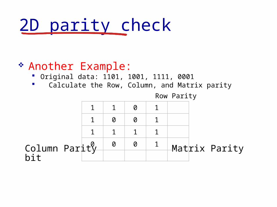
2D parity check
Another Example Original data 1101 1001 1111 0001 Calculate the Row Column and Matrix parity
Row Parity
Column Parity Matrix Parity bit
1 1 0 1
1 0 0 1
1 1 1 1
0 0 0 1
2D parity check
Another Example Received data 1101 1001 1111 0001 Calculate the Row Column and Matrix parity
Row Parity
Column Parity Matrix Parity bit
Possible to fix the problem without retransmitting the data
1 1 0 1 1
1 0 1 1 0
1 1 1 1 0
0 0 0 1 1
1 0 1 0 0
2D parity check
Another Example Received data 1101 1001 1111 0001 Calculate the Row Column and Matrix parity
Row Parity
Column Parity Matrix Parity bit
1 1 0 1 1
1 0 1 1 0
1 1 1 1 0
0 0 0 1 1
1 0 1 0 0
2D parity check
Another Example Received data 1101 1001 1111 0001 Calculate the Row Column and Matrix parity
Row Parity
Column Parity Matrix Parity bit
1 1 0 1 1
1 0 0 1 0
1 1 1 1 0
0 0 0 1 1
1 0 1 0 0
2D parity check
2D parity check can detect and correct all 1 bit errors
Error bit
0 1 1 0 1 0 0 1
1 0 1 1 0 1 0 0
0 0 0 0 1 1 0 1
1 1 1 0 1 0 1 1
1 0 0 1 0 1 1 0
1 0 0 0 1 1 0 1
2D parity check
2D parity check can detect all 2 bit errors Canrsquot correct all 2 bit errors Data must be
resent
Error bits
0 1 1 0 1 0 0 1
1 0 1 1 0 1 0 0
0 0 0 0 1 1 1 1
1 1 1 0 1 0 1 1
1 0 0 1 0 1 1 0
1 0 0 0 1 1 0 1
2D parity check
2D parity check can detect all 3 bit errors Canrsquot correct all 3 bit errors Data must be
resent
Error bits
0 1 1 0 1 0 0 1
1 0 1 1 0 1 0 0
0 0 0 0 1 1 1 1
1 1 0 0 1 0 1 1
1 0 0 1 0 1 1 0
1 0 0 0 1 1 0 1
2D parity check
2D parity check can detect most 4 bit errors Canrsquot correct all 4 bit errors Data must be
resent Example of a 4 bit error that is NOT
detected
Error bits
0 1 1 0 1 0 0 1
1 0 1 1 0 1 0 0
0 0 0 0 1 1 1 1
1 1 0 0 1 0 0 1
1 0 0 1 0 1 1 0
1 0 0 0 1 1 0 1
Link Layer 5-31
Internet checksum (review)
sender treat segment
contents as sequence of 16-bit integers
checksum addition (1rsquos complement sum) of segment contents
sender puts checksum value into UDP checksum field
receiver compute checksum of
received segment check if computed
checksum equals checksum field value NO - error detected YES - no error
detected But maybe errors nonetheless
goal detect ldquoerrorsrdquo (eg flipped bits) in transmitted packet (note used at transport layer only)
Link Layer 5-32
Cyclic redundancy check more powerful error-detection coding view data bits D as a binary number choose r+1 bit pattern (generator) G goal choose r CRC bits R such that
ltDRgt exactly divisible by G (modulo 2) receiver knows G divides ltDRgt by G If non-zero
remainder error detected can detect all burst errors less than r+1 bits
widely used in practice (Ethernet 80211 WiFi ATM)
Link Layer 5-33
Link layer LANs outline
51 introduction services
52 error detection correction
53 multiple access protocols
54 LANs addressing ARP Ethernet switches VLANS
55 link virtualization MPLS
56 data center networking
57 a day in the life of a web request
Link Layer 5-34
Multiple access links protocols
Two types of ldquolinksrdquo Point-to-point
PPP for dial-up access Point-to-point link between Ethernet switch host
Broadcast (shared wire or medium) Old-fashioned Ethernet Upstream HFC 80211 wireless LAN
shared wire (eg cabled Ethernet)
shared RF (eg 80211 WiFi)
shared RF(satellite)
humans at acocktail party
(shared air acoustical)
Link Layer 5-35
Multiple access protocols Single shared broadcast channel Two or more simultaneous transmissions by nodes
interference Collision if node receives two or more signals at the
same time
Multiple access protocol Distributed algorithm that determines how nodes share
channel ie determine when node can transmit Communication about channel sharing must use
channel itself No out-of-band channel for coordination
Link Layer 5-36
An ideal multiple access protocol
Given broadcast channel of rate R bps Desirable characteristics
1 When one node wants to transmit it can send at rate R2 When M nodes want to transmit each can send at average rate RM3 Fully decentralizedbull No special node to coordinate transmissionsbull No synchronization of clocks slots
4 Simple
Link Layer 5-37
MAC protocols taxonomy
Three broad classes Channel partitioning
Divide channel into smaller ldquopiecesrdquo (time slots frequency code)
Allocate piece to node for exclusive use FDMA TDMA CDMA
Random access Channel not divided allow collisions ldquoRecoverrdquo from collisions Ethernet
ldquoTaking turnsrdquo Nodes take turns but nodes with more to send can take longer
turns Token ring
Link Layer 5-38
Channel partitioning MAC protocols TDMA
TDMA time division multiple access Access to channel in rounds Each station gets fixed length slot (length = pkt
trans time) in each round Unused slots go idle Example
6-station LAN 134 have pkt slots 256 idle
1 3 4 1 3 4
6-slotframe
6-slotframe
Link Layer 5-39
FDMA frequency division multiple access Channel spectrum divided into frequency bands Each station assigned fixed frequency band Unused transmission time in frequency bands
go idle Example
6-station LAN 134 have pkt frequency bands 256 idle
freq
uenc
y ba
nds
time
FDM cable
Channel partitioning MAC protocols FDMA
Link Layer 5-40
Random access protocols When node has packet to send
Transmit at full channel data rate R No coordination among nodes
Two or more transmitting nodes ldquocollisionrdquo Random access MAC protocol specifies
How to detect collisions How to recover from collisions (eg via delayed
retransmissions) Examples of random access MAC protocols
ALOHA Slotted ALOHA CSMA CSMACD CSMACA
Link Layer 5-41
ALOHA
Aloha Norm Abramson (1969-1970) First radio packet network connecting the
Hawaiian Islands Two channels (different frequencies)
bull Downlink transmission from central host to secondary hosts
bull Uplink transmission from secondary host to central host
Important communication protocolbull First radio packet network decades before Wi-Fi
WiMAX Cellularbull Inspired CSMACD protocol used extensively by
8023 Ethernet
Link Layer 5-42
ALOHA Aloha simple no synchronization When frame first arrives
Transmit immediately High collision probability with multiple nodes
transmitting frame sent at t0 collides with other frames sent
in [t0-1t0+1]
Link Layer 5-43
ALOHA efficiencyP(success by given node) = P(node transmits)
P(no other node transmits in [t0-1t0]
P(no other node transmits in [t0-1t0]
= p (1-p)N-1 (1-p)N-1
= p (1-p)2(N-1)
hellip choosing optimum p and then letting n
= 1(2e) = 18
ALOHA bandwidth efficiency only 18Ex 18 Mbps max throughput over 100 Mbps link with multiple nodes
Link Layer 5-44
Slotted ALOHA
Assumptions all frames same size Time divided into equal size slots (time to transmit 1
frame) Nodes transmit only at the beginning of each slot Nodes are synchronized for slot timing not frame
transmission If 2 or more nodes transmit in slot all nodes detect
collision
Link Layer 5-45
Slotted ALOHA
Operation When node obtains fresh frame transmits in next slot
If no collision node can send new frame in next slot If collision node retransmits frame in each
subsequent slot with probability p until success
Link Layer 5-46
Pros single active node can
continuously transmit at full rate of channel
highly decentralized only slots in nodes need to be in sync
simple
Cons collisions wasting slots idle slots nodes may be able to
detect collision in less than time to transmit packet
clock synchronization
Slotted ALOHA1 1 1 1
2
3
2 2
3 3
node 1
node 2
node 3
C C CS S SE E E
Link Layer 5-47
Suppose N nodes with many frames to send each transmits in slot with probability p
Prob that given node has success in a slot = p(1-p)N-1
Prob that any node has a success = Np(1-p)N-1
Max efficiency find p that maximizes Np(1-p)N-1
For many nodes take limit of Np(1-p)N-1 as N goes to infinity gives
Max efficiency = 1e = 37
Efficiency long-run fraction of successful slots (many nodes all with many frames to send)
Best channel used for useful transmissions 37 of time
Better than unslotted ALOHA
Slotted ALOHA efficiency
Link Layer 5-48
CSMA (carrier sense multiple access)
CSMA listen before transmit If channel sensed is idle
Transmit entire frame If channel sensed is busy
Defer transmission
Human analogy donrsquot interrupt others
Link Layer 5-49
CSMA collisions Collisions can still occur
Propagation delay means two nodes may not hear each otherrsquos transmission
Collision Entire packet
transmission time wasted Distance amp propagation
delay play role in in determining collision probability
spatial layout of nodes
Link Layer 5-50
CSMACD (collision detection)
CSMACD Carrier Sense Multiple AccessCollision Detection Collisions detected within short time Colliding transmissions aborted reducing channel
wastage
Collision detection Easy in wired LANs measure signal strengths
compare transmitted received signals Difficult in wireless LANs received signal strength
overwhelmed by local transmission strength
Link Layer 5-51
CSMACD (collision detection)
spatial layout of nodes
Link Layer 5-52
Ethernet CSMACD algorithm1 NIC receives datagram from network layer creates
frame
2 If NIC senses channel idle starts frame transmission If NIC senses channel busy waits until channel idle then transmits
3 If NIC transmits entire frame without detecting another transmission NIC is done with frame
4 If NIC detects another transmission while transmitting aborts and sends jam signal
5 After aborting NIC enters binary (exponential) backoff state After mth collision NIC chooses K at random from 012 hellip
2m-1 NIC waits K512 bit times returns to Step 2 longer backoff intervals with more collisions
Link Layer 5-53
CSMACD efficiency
Tprop = max prop delay between 2 nodes in LAN ttrans = time to transmit max-size frame
Efficiency goes to 1 as tprop goes to 0 as ttrans goes to infinity
Better performance than ALOHA Also simple cheap and decentralized
transprop ttefficiency
51
1
Link Layer 5-54
ldquoTaking turnsrdquo MAC protocols
Channel partitioning MAC protocols Share channel efficiently and fairly at high
load Inefficient at low load delay in channel
access 1N bandwidth allocated even if only 1 active node
Random access MAC protocols Efficient at low load single node can fully
utilize channel High load collision overhead
ldquoTaking turnsrdquo protocols Look for best of both worlds
Link Layer 5-55
Polling Master node ldquoinvitesrdquo slave
nodes to transmit in turn Typically used with ldquodumbrdquo
slave devices Concerns
bull Polling overhead bull Latencybull Single point of failure
(master)
master
slaves
poll
data
data
ldquoTaking turnsrdquo MAC protocols
Link Layer 5-56
Token passing Control token passed from
one node to next sequentially Token message Concerns
Token overhead Latency Single point of failure
(token)
T
data
(nothingto send)
T
ldquoTaking turnsrdquo MAC protocols
cable headend
CMTS
ISP
cable modemtermination system
Multiple downstream (broadcast) channels Multiple upstream channels Multiple access all users contend for certain upstream
channel time slots (others assigned)
Cable access network
cablemodem
splitter
hellip
hellip
Internet framesTV channels control transmitted downstream at different frequencies
upstream Internet frames TV control transmitted upstream at different frequencies in time slots
Link Layer 5-58
Summary of MAC protocols
Channel partitioning By time frequency or code Time Division Frequency Division
Random access (dynamic) ALOHA S-ALOHA CSMA CSMACD Carrier sensing
Easy in some technologies (wire) hard in others (wireless) CSMACD used in Ethernet CSMACA used in 80211
Taking turns Polling from central site token passing Bluetooth FDDI token ring
- Slide 1
- Chapter 5 Link layer
- Link layer LANs outline
- Link layer introduction
- Link layer introduction (2)
- Link layer context
- Link layer context (2)
- Link layer services
- Link layer services (more)
- Link layer services (more) (2)
- Where is the link layer implemented
- Where is the link layer implemented (2)
- Adaptors communicating
- Link layer LANs outline (2)
- Error detection
- Error detection (2)
- Error Detection and Correction
- Problem with the simple approach
- Calculating bit string parity
- Parity check code
- 2D parity check code
- 2D parity check
- 2D parity check (2)
- 2D parity check (3)
- 2D parity check (4)
- 2D parity check (5)
- 2D parity check (6)
- 2D parity check (7)
- 2D parity check (8)
- 2D parity check (9)
- Internet checksum (review)
- Cyclic redundancy check
- Link layer LANs outline (3)
- Multiple access links protocols
- Multiple access protocols
- An ideal multiple access protocol
- MAC protocols taxonomy
- Channel partitioning MAC protocols TDMA
- Channel partitioning MAC protocols FDMA
- Random access protocols
- ALOHA
- ALOHA (2)
- ALOHA efficiency
- Slotted ALOHA
- Slotted ALOHA (2)
- Slotted ALOHA (3)
- Slotted ALOHA efficiency
- CSMA (carrier sense multiple access)
- CSMA collisions
- CSMACD (collision detection)
- CSMACD (collision detection) (2)
- Ethernet CSMACD algorithm
- CSMACD efficiency
- ldquoTaking turnsrdquo MAC protocols
- ldquoTaking turnsrdquo MAC protocols (2)
- ldquoTaking turnsrdquo MAC protocols (3)
- Slide 57
- Summary of MAC protocols
-
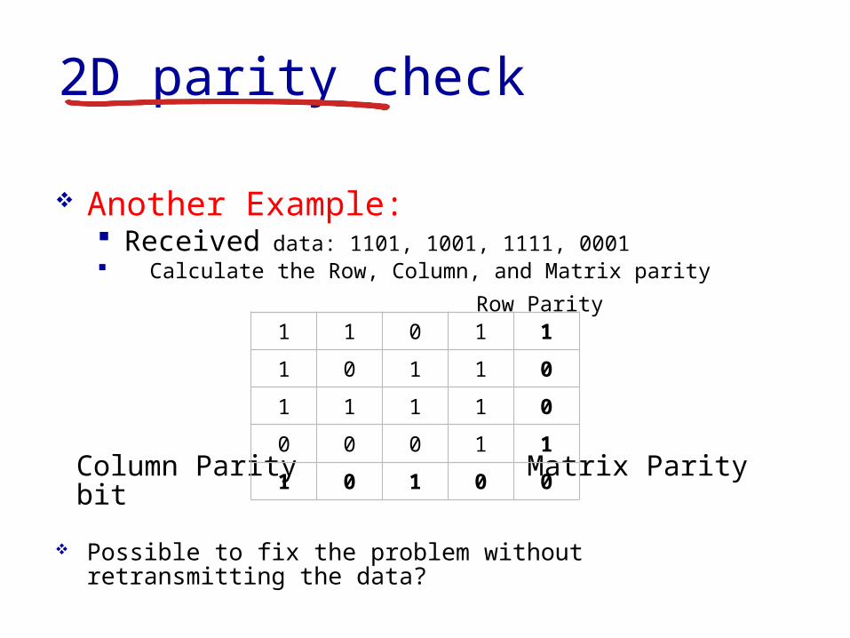
2D parity check
Another Example Received data 1101 1001 1111 0001 Calculate the Row Column and Matrix parity
Row Parity
Column Parity Matrix Parity bit
Possible to fix the problem without retransmitting the data
1 1 0 1 1
1 0 1 1 0
1 1 1 1 0
0 0 0 1 1
1 0 1 0 0
2D parity check
Another Example Received data 1101 1001 1111 0001 Calculate the Row Column and Matrix parity
Row Parity
Column Parity Matrix Parity bit
1 1 0 1 1
1 0 1 1 0
1 1 1 1 0
0 0 0 1 1
1 0 1 0 0
2D parity check
Another Example Received data 1101 1001 1111 0001 Calculate the Row Column and Matrix parity
Row Parity
Column Parity Matrix Parity bit
1 1 0 1 1
1 0 0 1 0
1 1 1 1 0
0 0 0 1 1
1 0 1 0 0
2D parity check
2D parity check can detect and correct all 1 bit errors
Error bit
0 1 1 0 1 0 0 1
1 0 1 1 0 1 0 0
0 0 0 0 1 1 0 1
1 1 1 0 1 0 1 1
1 0 0 1 0 1 1 0
1 0 0 0 1 1 0 1
2D parity check
2D parity check can detect all 2 bit errors Canrsquot correct all 2 bit errors Data must be
resent
Error bits
0 1 1 0 1 0 0 1
1 0 1 1 0 1 0 0
0 0 0 0 1 1 1 1
1 1 1 0 1 0 1 1
1 0 0 1 0 1 1 0
1 0 0 0 1 1 0 1
2D parity check
2D parity check can detect all 3 bit errors Canrsquot correct all 3 bit errors Data must be
resent
Error bits
0 1 1 0 1 0 0 1
1 0 1 1 0 1 0 0
0 0 0 0 1 1 1 1
1 1 0 0 1 0 1 1
1 0 0 1 0 1 1 0
1 0 0 0 1 1 0 1
2D parity check
2D parity check can detect most 4 bit errors Canrsquot correct all 4 bit errors Data must be
resent Example of a 4 bit error that is NOT
detected
Error bits
0 1 1 0 1 0 0 1
1 0 1 1 0 1 0 0
0 0 0 0 1 1 1 1
1 1 0 0 1 0 0 1
1 0 0 1 0 1 1 0
1 0 0 0 1 1 0 1
Link Layer 5-31
Internet checksum (review)
sender treat segment
contents as sequence of 16-bit integers
checksum addition (1rsquos complement sum) of segment contents
sender puts checksum value into UDP checksum field
receiver compute checksum of
received segment check if computed
checksum equals checksum field value NO - error detected YES - no error
detected But maybe errors nonetheless
goal detect ldquoerrorsrdquo (eg flipped bits) in transmitted packet (note used at transport layer only)
Link Layer 5-32
Cyclic redundancy check more powerful error-detection coding view data bits D as a binary number choose r+1 bit pattern (generator) G goal choose r CRC bits R such that
ltDRgt exactly divisible by G (modulo 2) receiver knows G divides ltDRgt by G If non-zero
remainder error detected can detect all burst errors less than r+1 bits
widely used in practice (Ethernet 80211 WiFi ATM)
Link Layer 5-33
Link layer LANs outline
51 introduction services
52 error detection correction
53 multiple access protocols
54 LANs addressing ARP Ethernet switches VLANS
55 link virtualization MPLS
56 data center networking
57 a day in the life of a web request
Link Layer 5-34
Multiple access links protocols
Two types of ldquolinksrdquo Point-to-point
PPP for dial-up access Point-to-point link between Ethernet switch host
Broadcast (shared wire or medium) Old-fashioned Ethernet Upstream HFC 80211 wireless LAN
shared wire (eg cabled Ethernet)
shared RF (eg 80211 WiFi)
shared RF(satellite)
humans at acocktail party
(shared air acoustical)
Link Layer 5-35
Multiple access protocols Single shared broadcast channel Two or more simultaneous transmissions by nodes
interference Collision if node receives two or more signals at the
same time
Multiple access protocol Distributed algorithm that determines how nodes share
channel ie determine when node can transmit Communication about channel sharing must use
channel itself No out-of-band channel for coordination
Link Layer 5-36
An ideal multiple access protocol
Given broadcast channel of rate R bps Desirable characteristics
1 When one node wants to transmit it can send at rate R2 When M nodes want to transmit each can send at average rate RM3 Fully decentralizedbull No special node to coordinate transmissionsbull No synchronization of clocks slots
4 Simple
Link Layer 5-37
MAC protocols taxonomy
Three broad classes Channel partitioning
Divide channel into smaller ldquopiecesrdquo (time slots frequency code)
Allocate piece to node for exclusive use FDMA TDMA CDMA
Random access Channel not divided allow collisions ldquoRecoverrdquo from collisions Ethernet
ldquoTaking turnsrdquo Nodes take turns but nodes with more to send can take longer
turns Token ring
Link Layer 5-38
Channel partitioning MAC protocols TDMA
TDMA time division multiple access Access to channel in rounds Each station gets fixed length slot (length = pkt
trans time) in each round Unused slots go idle Example
6-station LAN 134 have pkt slots 256 idle
1 3 4 1 3 4
6-slotframe
6-slotframe
Link Layer 5-39
FDMA frequency division multiple access Channel spectrum divided into frequency bands Each station assigned fixed frequency band Unused transmission time in frequency bands
go idle Example
6-station LAN 134 have pkt frequency bands 256 idle
freq
uenc
y ba
nds
time
FDM cable
Channel partitioning MAC protocols FDMA
Link Layer 5-40
Random access protocols When node has packet to send
Transmit at full channel data rate R No coordination among nodes
Two or more transmitting nodes ldquocollisionrdquo Random access MAC protocol specifies
How to detect collisions How to recover from collisions (eg via delayed
retransmissions) Examples of random access MAC protocols
ALOHA Slotted ALOHA CSMA CSMACD CSMACA
Link Layer 5-41
ALOHA
Aloha Norm Abramson (1969-1970) First radio packet network connecting the
Hawaiian Islands Two channels (different frequencies)
bull Downlink transmission from central host to secondary hosts
bull Uplink transmission from secondary host to central host
Important communication protocolbull First radio packet network decades before Wi-Fi
WiMAX Cellularbull Inspired CSMACD protocol used extensively by
8023 Ethernet
Link Layer 5-42
ALOHA Aloha simple no synchronization When frame first arrives
Transmit immediately High collision probability with multiple nodes
transmitting frame sent at t0 collides with other frames sent
in [t0-1t0+1]
Link Layer 5-43
ALOHA efficiencyP(success by given node) = P(node transmits)
P(no other node transmits in [t0-1t0]
P(no other node transmits in [t0-1t0]
= p (1-p)N-1 (1-p)N-1
= p (1-p)2(N-1)
hellip choosing optimum p and then letting n
= 1(2e) = 18
ALOHA bandwidth efficiency only 18Ex 18 Mbps max throughput over 100 Mbps link with multiple nodes
Link Layer 5-44
Slotted ALOHA
Assumptions all frames same size Time divided into equal size slots (time to transmit 1
frame) Nodes transmit only at the beginning of each slot Nodes are synchronized for slot timing not frame
transmission If 2 or more nodes transmit in slot all nodes detect
collision
Link Layer 5-45
Slotted ALOHA
Operation When node obtains fresh frame transmits in next slot
If no collision node can send new frame in next slot If collision node retransmits frame in each
subsequent slot with probability p until success
Link Layer 5-46
Pros single active node can
continuously transmit at full rate of channel
highly decentralized only slots in nodes need to be in sync
simple
Cons collisions wasting slots idle slots nodes may be able to
detect collision in less than time to transmit packet
clock synchronization
Slotted ALOHA1 1 1 1
2
3
2 2
3 3
node 1
node 2
node 3
C C CS S SE E E
Link Layer 5-47
Suppose N nodes with many frames to send each transmits in slot with probability p
Prob that given node has success in a slot = p(1-p)N-1
Prob that any node has a success = Np(1-p)N-1
Max efficiency find p that maximizes Np(1-p)N-1
For many nodes take limit of Np(1-p)N-1 as N goes to infinity gives
Max efficiency = 1e = 37
Efficiency long-run fraction of successful slots (many nodes all with many frames to send)
Best channel used for useful transmissions 37 of time
Better than unslotted ALOHA
Slotted ALOHA efficiency
Link Layer 5-48
CSMA (carrier sense multiple access)
CSMA listen before transmit If channel sensed is idle
Transmit entire frame If channel sensed is busy
Defer transmission
Human analogy donrsquot interrupt others
Link Layer 5-49
CSMA collisions Collisions can still occur
Propagation delay means two nodes may not hear each otherrsquos transmission
Collision Entire packet
transmission time wasted Distance amp propagation
delay play role in in determining collision probability
spatial layout of nodes
Link Layer 5-50
CSMACD (collision detection)
CSMACD Carrier Sense Multiple AccessCollision Detection Collisions detected within short time Colliding transmissions aborted reducing channel
wastage
Collision detection Easy in wired LANs measure signal strengths
compare transmitted received signals Difficult in wireless LANs received signal strength
overwhelmed by local transmission strength
Link Layer 5-51
CSMACD (collision detection)
spatial layout of nodes
Link Layer 5-52
Ethernet CSMACD algorithm1 NIC receives datagram from network layer creates
frame
2 If NIC senses channel idle starts frame transmission If NIC senses channel busy waits until channel idle then transmits
3 If NIC transmits entire frame without detecting another transmission NIC is done with frame
4 If NIC detects another transmission while transmitting aborts and sends jam signal
5 After aborting NIC enters binary (exponential) backoff state After mth collision NIC chooses K at random from 012 hellip
2m-1 NIC waits K512 bit times returns to Step 2 longer backoff intervals with more collisions
Link Layer 5-53
CSMACD efficiency
Tprop = max prop delay between 2 nodes in LAN ttrans = time to transmit max-size frame
Efficiency goes to 1 as tprop goes to 0 as ttrans goes to infinity
Better performance than ALOHA Also simple cheap and decentralized
transprop ttefficiency
51
1
Link Layer 5-54
ldquoTaking turnsrdquo MAC protocols
Channel partitioning MAC protocols Share channel efficiently and fairly at high
load Inefficient at low load delay in channel
access 1N bandwidth allocated even if only 1 active node
Random access MAC protocols Efficient at low load single node can fully
utilize channel High load collision overhead
ldquoTaking turnsrdquo protocols Look for best of both worlds
Link Layer 5-55
Polling Master node ldquoinvitesrdquo slave
nodes to transmit in turn Typically used with ldquodumbrdquo
slave devices Concerns
bull Polling overhead bull Latencybull Single point of failure
(master)
master
slaves
poll
data
data
ldquoTaking turnsrdquo MAC protocols
Link Layer 5-56
Token passing Control token passed from
one node to next sequentially Token message Concerns
Token overhead Latency Single point of failure
(token)
T
data
(nothingto send)
T
ldquoTaking turnsrdquo MAC protocols
cable headend
CMTS
ISP
cable modemtermination system
Multiple downstream (broadcast) channels Multiple upstream channels Multiple access all users contend for certain upstream
channel time slots (others assigned)
Cable access network
cablemodem
splitter
hellip
hellip
Internet framesTV channels control transmitted downstream at different frequencies
upstream Internet frames TV control transmitted upstream at different frequencies in time slots
Link Layer 5-58
Summary of MAC protocols
Channel partitioning By time frequency or code Time Division Frequency Division
Random access (dynamic) ALOHA S-ALOHA CSMA CSMACD Carrier sensing
Easy in some technologies (wire) hard in others (wireless) CSMACD used in Ethernet CSMACA used in 80211
Taking turns Polling from central site token passing Bluetooth FDDI token ring
- Slide 1
- Chapter 5 Link layer
- Link layer LANs outline
- Link layer introduction
- Link layer introduction (2)
- Link layer context
- Link layer context (2)
- Link layer services
- Link layer services (more)
- Link layer services (more) (2)
- Where is the link layer implemented
- Where is the link layer implemented (2)
- Adaptors communicating
- Link layer LANs outline (2)
- Error detection
- Error detection (2)
- Error Detection and Correction
- Problem with the simple approach
- Calculating bit string parity
- Parity check code
- 2D parity check code
- 2D parity check
- 2D parity check (2)
- 2D parity check (3)
- 2D parity check (4)
- 2D parity check (5)
- 2D parity check (6)
- 2D parity check (7)
- 2D parity check (8)
- 2D parity check (9)
- Internet checksum (review)
- Cyclic redundancy check
- Link layer LANs outline (3)
- Multiple access links protocols
- Multiple access protocols
- An ideal multiple access protocol
- MAC protocols taxonomy
- Channel partitioning MAC protocols TDMA
- Channel partitioning MAC protocols FDMA
- Random access protocols
- ALOHA
- ALOHA (2)
- ALOHA efficiency
- Slotted ALOHA
- Slotted ALOHA (2)
- Slotted ALOHA (3)
- Slotted ALOHA efficiency
- CSMA (carrier sense multiple access)
- CSMA collisions
- CSMACD (collision detection)
- CSMACD (collision detection) (2)
- Ethernet CSMACD algorithm
- CSMACD efficiency
- ldquoTaking turnsrdquo MAC protocols
- ldquoTaking turnsrdquo MAC protocols (2)
- ldquoTaking turnsrdquo MAC protocols (3)
- Slide 57
- Summary of MAC protocols
-
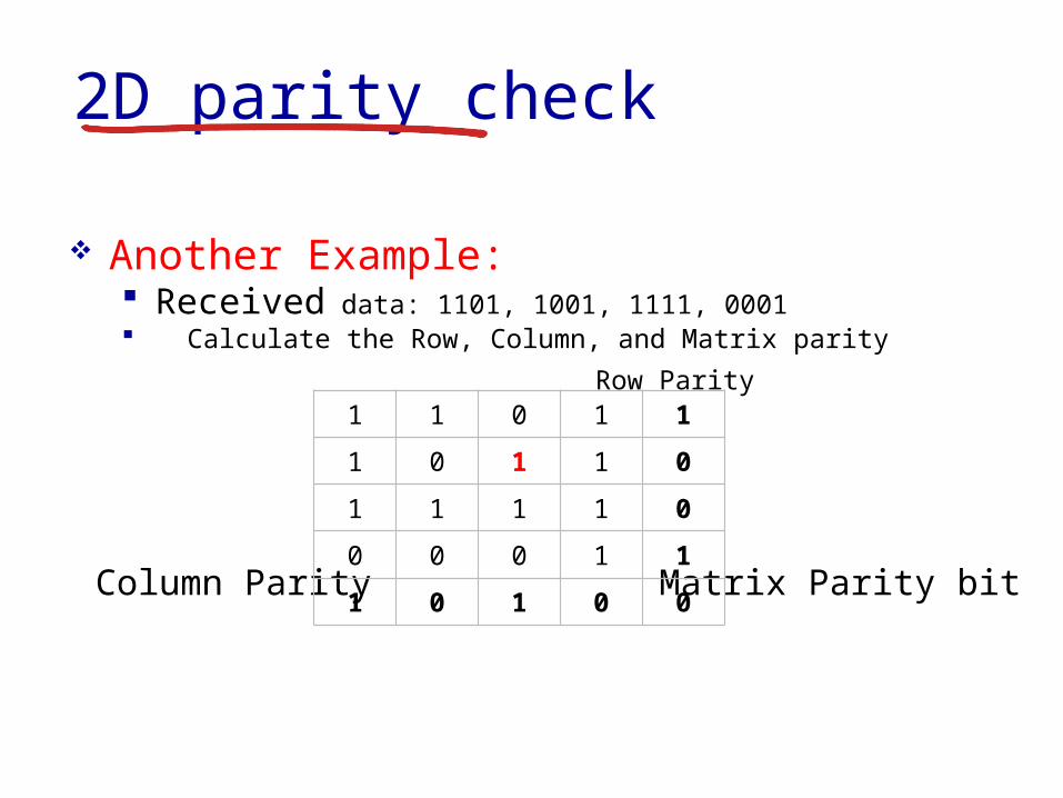
2D parity check
Another Example Received data 1101 1001 1111 0001 Calculate the Row Column and Matrix parity
Row Parity
Column Parity Matrix Parity bit
1 1 0 1 1
1 0 1 1 0
1 1 1 1 0
0 0 0 1 1
1 0 1 0 0
2D parity check
Another Example Received data 1101 1001 1111 0001 Calculate the Row Column and Matrix parity
Row Parity
Column Parity Matrix Parity bit
1 1 0 1 1
1 0 0 1 0
1 1 1 1 0
0 0 0 1 1
1 0 1 0 0
2D parity check
2D parity check can detect and correct all 1 bit errors
Error bit
0 1 1 0 1 0 0 1
1 0 1 1 0 1 0 0
0 0 0 0 1 1 0 1
1 1 1 0 1 0 1 1
1 0 0 1 0 1 1 0
1 0 0 0 1 1 0 1
2D parity check
2D parity check can detect all 2 bit errors Canrsquot correct all 2 bit errors Data must be
resent
Error bits
0 1 1 0 1 0 0 1
1 0 1 1 0 1 0 0
0 0 0 0 1 1 1 1
1 1 1 0 1 0 1 1
1 0 0 1 0 1 1 0
1 0 0 0 1 1 0 1
2D parity check
2D parity check can detect all 3 bit errors Canrsquot correct all 3 bit errors Data must be
resent
Error bits
0 1 1 0 1 0 0 1
1 0 1 1 0 1 0 0
0 0 0 0 1 1 1 1
1 1 0 0 1 0 1 1
1 0 0 1 0 1 1 0
1 0 0 0 1 1 0 1
2D parity check
2D parity check can detect most 4 bit errors Canrsquot correct all 4 bit errors Data must be
resent Example of a 4 bit error that is NOT
detected
Error bits
0 1 1 0 1 0 0 1
1 0 1 1 0 1 0 0
0 0 0 0 1 1 1 1
1 1 0 0 1 0 0 1
1 0 0 1 0 1 1 0
1 0 0 0 1 1 0 1
Link Layer 5-31
Internet checksum (review)
sender treat segment
contents as sequence of 16-bit integers
checksum addition (1rsquos complement sum) of segment contents
sender puts checksum value into UDP checksum field
receiver compute checksum of
received segment check if computed
checksum equals checksum field value NO - error detected YES - no error
detected But maybe errors nonetheless
goal detect ldquoerrorsrdquo (eg flipped bits) in transmitted packet (note used at transport layer only)
Link Layer 5-32
Cyclic redundancy check more powerful error-detection coding view data bits D as a binary number choose r+1 bit pattern (generator) G goal choose r CRC bits R such that
ltDRgt exactly divisible by G (modulo 2) receiver knows G divides ltDRgt by G If non-zero
remainder error detected can detect all burst errors less than r+1 bits
widely used in practice (Ethernet 80211 WiFi ATM)
Link Layer 5-33
Link layer LANs outline
51 introduction services
52 error detection correction
53 multiple access protocols
54 LANs addressing ARP Ethernet switches VLANS
55 link virtualization MPLS
56 data center networking
57 a day in the life of a web request
Link Layer 5-34
Multiple access links protocols
Two types of ldquolinksrdquo Point-to-point
PPP for dial-up access Point-to-point link between Ethernet switch host
Broadcast (shared wire or medium) Old-fashioned Ethernet Upstream HFC 80211 wireless LAN
shared wire (eg cabled Ethernet)
shared RF (eg 80211 WiFi)
shared RF(satellite)
humans at acocktail party
(shared air acoustical)
Link Layer 5-35
Multiple access protocols Single shared broadcast channel Two or more simultaneous transmissions by nodes
interference Collision if node receives two or more signals at the
same time
Multiple access protocol Distributed algorithm that determines how nodes share
channel ie determine when node can transmit Communication about channel sharing must use
channel itself No out-of-band channel for coordination
Link Layer 5-36
An ideal multiple access protocol
Given broadcast channel of rate R bps Desirable characteristics
1 When one node wants to transmit it can send at rate R2 When M nodes want to transmit each can send at average rate RM3 Fully decentralizedbull No special node to coordinate transmissionsbull No synchronization of clocks slots
4 Simple
Link Layer 5-37
MAC protocols taxonomy
Three broad classes Channel partitioning
Divide channel into smaller ldquopiecesrdquo (time slots frequency code)
Allocate piece to node for exclusive use FDMA TDMA CDMA
Random access Channel not divided allow collisions ldquoRecoverrdquo from collisions Ethernet
ldquoTaking turnsrdquo Nodes take turns but nodes with more to send can take longer
turns Token ring
Link Layer 5-38
Channel partitioning MAC protocols TDMA
TDMA time division multiple access Access to channel in rounds Each station gets fixed length slot (length = pkt
trans time) in each round Unused slots go idle Example
6-station LAN 134 have pkt slots 256 idle
1 3 4 1 3 4
6-slotframe
6-slotframe
Link Layer 5-39
FDMA frequency division multiple access Channel spectrum divided into frequency bands Each station assigned fixed frequency band Unused transmission time in frequency bands
go idle Example
6-station LAN 134 have pkt frequency bands 256 idle
freq
uenc
y ba
nds
time
FDM cable
Channel partitioning MAC protocols FDMA
Link Layer 5-40
Random access protocols When node has packet to send
Transmit at full channel data rate R No coordination among nodes
Two or more transmitting nodes ldquocollisionrdquo Random access MAC protocol specifies
How to detect collisions How to recover from collisions (eg via delayed
retransmissions) Examples of random access MAC protocols
ALOHA Slotted ALOHA CSMA CSMACD CSMACA
Link Layer 5-41
ALOHA
Aloha Norm Abramson (1969-1970) First radio packet network connecting the
Hawaiian Islands Two channels (different frequencies)
bull Downlink transmission from central host to secondary hosts
bull Uplink transmission from secondary host to central host
Important communication protocolbull First radio packet network decades before Wi-Fi
WiMAX Cellularbull Inspired CSMACD protocol used extensively by
8023 Ethernet
Link Layer 5-42
ALOHA Aloha simple no synchronization When frame first arrives
Transmit immediately High collision probability with multiple nodes
transmitting frame sent at t0 collides with other frames sent
in [t0-1t0+1]
Link Layer 5-43
ALOHA efficiencyP(success by given node) = P(node transmits)
P(no other node transmits in [t0-1t0]
P(no other node transmits in [t0-1t0]
= p (1-p)N-1 (1-p)N-1
= p (1-p)2(N-1)
hellip choosing optimum p and then letting n
= 1(2e) = 18
ALOHA bandwidth efficiency only 18Ex 18 Mbps max throughput over 100 Mbps link with multiple nodes
Link Layer 5-44
Slotted ALOHA
Assumptions all frames same size Time divided into equal size slots (time to transmit 1
frame) Nodes transmit only at the beginning of each slot Nodes are synchronized for slot timing not frame
transmission If 2 or more nodes transmit in slot all nodes detect
collision
Link Layer 5-45
Slotted ALOHA
Operation When node obtains fresh frame transmits in next slot
If no collision node can send new frame in next slot If collision node retransmits frame in each
subsequent slot with probability p until success
Link Layer 5-46
Pros single active node can
continuously transmit at full rate of channel
highly decentralized only slots in nodes need to be in sync
simple
Cons collisions wasting slots idle slots nodes may be able to
detect collision in less than time to transmit packet
clock synchronization
Slotted ALOHA1 1 1 1
2
3
2 2
3 3
node 1
node 2
node 3
C C CS S SE E E
Link Layer 5-47
Suppose N nodes with many frames to send each transmits in slot with probability p
Prob that given node has success in a slot = p(1-p)N-1
Prob that any node has a success = Np(1-p)N-1
Max efficiency find p that maximizes Np(1-p)N-1
For many nodes take limit of Np(1-p)N-1 as N goes to infinity gives
Max efficiency = 1e = 37
Efficiency long-run fraction of successful slots (many nodes all with many frames to send)
Best channel used for useful transmissions 37 of time
Better than unslotted ALOHA
Slotted ALOHA efficiency
Link Layer 5-48
CSMA (carrier sense multiple access)
CSMA listen before transmit If channel sensed is idle
Transmit entire frame If channel sensed is busy
Defer transmission
Human analogy donrsquot interrupt others
Link Layer 5-49
CSMA collisions Collisions can still occur
Propagation delay means two nodes may not hear each otherrsquos transmission
Collision Entire packet
transmission time wasted Distance amp propagation
delay play role in in determining collision probability
spatial layout of nodes
Link Layer 5-50
CSMACD (collision detection)
CSMACD Carrier Sense Multiple AccessCollision Detection Collisions detected within short time Colliding transmissions aborted reducing channel
wastage
Collision detection Easy in wired LANs measure signal strengths
compare transmitted received signals Difficult in wireless LANs received signal strength
overwhelmed by local transmission strength
Link Layer 5-51
CSMACD (collision detection)
spatial layout of nodes
Link Layer 5-52
Ethernet CSMACD algorithm1 NIC receives datagram from network layer creates
frame
2 If NIC senses channel idle starts frame transmission If NIC senses channel busy waits until channel idle then transmits
3 If NIC transmits entire frame without detecting another transmission NIC is done with frame
4 If NIC detects another transmission while transmitting aborts and sends jam signal
5 After aborting NIC enters binary (exponential) backoff state After mth collision NIC chooses K at random from 012 hellip
2m-1 NIC waits K512 bit times returns to Step 2 longer backoff intervals with more collisions
Link Layer 5-53
CSMACD efficiency
Tprop = max prop delay between 2 nodes in LAN ttrans = time to transmit max-size frame
Efficiency goes to 1 as tprop goes to 0 as ttrans goes to infinity
Better performance than ALOHA Also simple cheap and decentralized
transprop ttefficiency
51
1
Link Layer 5-54
ldquoTaking turnsrdquo MAC protocols
Channel partitioning MAC protocols Share channel efficiently and fairly at high
load Inefficient at low load delay in channel
access 1N bandwidth allocated even if only 1 active node
Random access MAC protocols Efficient at low load single node can fully
utilize channel High load collision overhead
ldquoTaking turnsrdquo protocols Look for best of both worlds
Link Layer 5-55
Polling Master node ldquoinvitesrdquo slave
nodes to transmit in turn Typically used with ldquodumbrdquo
slave devices Concerns
bull Polling overhead bull Latencybull Single point of failure
(master)
master
slaves
poll
data
data
ldquoTaking turnsrdquo MAC protocols
Link Layer 5-56
Token passing Control token passed from
one node to next sequentially Token message Concerns
Token overhead Latency Single point of failure
(token)
T
data
(nothingto send)
T
ldquoTaking turnsrdquo MAC protocols
cable headend
CMTS
ISP
cable modemtermination system
Multiple downstream (broadcast) channels Multiple upstream channels Multiple access all users contend for certain upstream
channel time slots (others assigned)
Cable access network
cablemodem
splitter
hellip
hellip
Internet framesTV channels control transmitted downstream at different frequencies
upstream Internet frames TV control transmitted upstream at different frequencies in time slots
Link Layer 5-58
Summary of MAC protocols
Channel partitioning By time frequency or code Time Division Frequency Division
Random access (dynamic) ALOHA S-ALOHA CSMA CSMACD Carrier sensing
Easy in some technologies (wire) hard in others (wireless) CSMACD used in Ethernet CSMACA used in 80211
Taking turns Polling from central site token passing Bluetooth FDDI token ring
- Slide 1
- Chapter 5 Link layer
- Link layer LANs outline
- Link layer introduction
- Link layer introduction (2)
- Link layer context
- Link layer context (2)
- Link layer services
- Link layer services (more)
- Link layer services (more) (2)
- Where is the link layer implemented
- Where is the link layer implemented (2)
- Adaptors communicating
- Link layer LANs outline (2)
- Error detection
- Error detection (2)
- Error Detection and Correction
- Problem with the simple approach
- Calculating bit string parity
- Parity check code
- 2D parity check code
- 2D parity check
- 2D parity check (2)
- 2D parity check (3)
- 2D parity check (4)
- 2D parity check (5)
- 2D parity check (6)
- 2D parity check (7)
- 2D parity check (8)
- 2D parity check (9)
- Internet checksum (review)
- Cyclic redundancy check
- Link layer LANs outline (3)
- Multiple access links protocols
- Multiple access protocols
- An ideal multiple access protocol
- MAC protocols taxonomy
- Channel partitioning MAC protocols TDMA
- Channel partitioning MAC protocols FDMA
- Random access protocols
- ALOHA
- ALOHA (2)
- ALOHA efficiency
- Slotted ALOHA
- Slotted ALOHA (2)
- Slotted ALOHA (3)
- Slotted ALOHA efficiency
- CSMA (carrier sense multiple access)
- CSMA collisions
- CSMACD (collision detection)
- CSMACD (collision detection) (2)
- Ethernet CSMACD algorithm
- CSMACD efficiency
- ldquoTaking turnsrdquo MAC protocols
- ldquoTaking turnsrdquo MAC protocols (2)
- ldquoTaking turnsrdquo MAC protocols (3)
- Slide 57
- Summary of MAC protocols
-
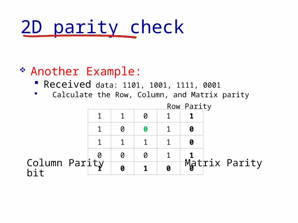
2D parity check
Another Example Received data 1101 1001 1111 0001 Calculate the Row Column and Matrix parity
Row Parity
Column Parity Matrix Parity bit
1 1 0 1 1
1 0 0 1 0
1 1 1 1 0
0 0 0 1 1
1 0 1 0 0
2D parity check
2D parity check can detect and correct all 1 bit errors
Error bit
0 1 1 0 1 0 0 1
1 0 1 1 0 1 0 0
0 0 0 0 1 1 0 1
1 1 1 0 1 0 1 1
1 0 0 1 0 1 1 0
1 0 0 0 1 1 0 1
2D parity check
2D parity check can detect all 2 bit errors Canrsquot correct all 2 bit errors Data must be
resent
Error bits
0 1 1 0 1 0 0 1
1 0 1 1 0 1 0 0
0 0 0 0 1 1 1 1
1 1 1 0 1 0 1 1
1 0 0 1 0 1 1 0
1 0 0 0 1 1 0 1
2D parity check
2D parity check can detect all 3 bit errors Canrsquot correct all 3 bit errors Data must be
resent
Error bits
0 1 1 0 1 0 0 1
1 0 1 1 0 1 0 0
0 0 0 0 1 1 1 1
1 1 0 0 1 0 1 1
1 0 0 1 0 1 1 0
1 0 0 0 1 1 0 1
2D parity check
2D parity check can detect most 4 bit errors Canrsquot correct all 4 bit errors Data must be
resent Example of a 4 bit error that is NOT
detected
Error bits
0 1 1 0 1 0 0 1
1 0 1 1 0 1 0 0
0 0 0 0 1 1 1 1
1 1 0 0 1 0 0 1
1 0 0 1 0 1 1 0
1 0 0 0 1 1 0 1
Link Layer 5-31
Internet checksum (review)
sender treat segment
contents as sequence of 16-bit integers
checksum addition (1rsquos complement sum) of segment contents
sender puts checksum value into UDP checksum field
receiver compute checksum of
received segment check if computed
checksum equals checksum field value NO - error detected YES - no error
detected But maybe errors nonetheless
goal detect ldquoerrorsrdquo (eg flipped bits) in transmitted packet (note used at transport layer only)
Link Layer 5-32
Cyclic redundancy check more powerful error-detection coding view data bits D as a binary number choose r+1 bit pattern (generator) G goal choose r CRC bits R such that
ltDRgt exactly divisible by G (modulo 2) receiver knows G divides ltDRgt by G If non-zero
remainder error detected can detect all burst errors less than r+1 bits
widely used in practice (Ethernet 80211 WiFi ATM)
Link Layer 5-33
Link layer LANs outline
51 introduction services
52 error detection correction
53 multiple access protocols
54 LANs addressing ARP Ethernet switches VLANS
55 link virtualization MPLS
56 data center networking
57 a day in the life of a web request
Link Layer 5-34
Multiple access links protocols
Two types of ldquolinksrdquo Point-to-point
PPP for dial-up access Point-to-point link between Ethernet switch host
Broadcast (shared wire or medium) Old-fashioned Ethernet Upstream HFC 80211 wireless LAN
shared wire (eg cabled Ethernet)
shared RF (eg 80211 WiFi)
shared RF(satellite)
humans at acocktail party
(shared air acoustical)
Link Layer 5-35
Multiple access protocols Single shared broadcast channel Two or more simultaneous transmissions by nodes
interference Collision if node receives two or more signals at the
same time
Multiple access protocol Distributed algorithm that determines how nodes share
channel ie determine when node can transmit Communication about channel sharing must use
channel itself No out-of-band channel for coordination
Link Layer 5-36
An ideal multiple access protocol
Given broadcast channel of rate R bps Desirable characteristics
1 When one node wants to transmit it can send at rate R2 When M nodes want to transmit each can send at average rate RM3 Fully decentralizedbull No special node to coordinate transmissionsbull No synchronization of clocks slots
4 Simple
Link Layer 5-37
MAC protocols taxonomy
Three broad classes Channel partitioning
Divide channel into smaller ldquopiecesrdquo (time slots frequency code)
Allocate piece to node for exclusive use FDMA TDMA CDMA
Random access Channel not divided allow collisions ldquoRecoverrdquo from collisions Ethernet
ldquoTaking turnsrdquo Nodes take turns but nodes with more to send can take longer
turns Token ring
Link Layer 5-38
Channel partitioning MAC protocols TDMA
TDMA time division multiple access Access to channel in rounds Each station gets fixed length slot (length = pkt
trans time) in each round Unused slots go idle Example
6-station LAN 134 have pkt slots 256 idle
1 3 4 1 3 4
6-slotframe
6-slotframe
Link Layer 5-39
FDMA frequency division multiple access Channel spectrum divided into frequency bands Each station assigned fixed frequency band Unused transmission time in frequency bands
go idle Example
6-station LAN 134 have pkt frequency bands 256 idle
freq
uenc
y ba
nds
time
FDM cable
Channel partitioning MAC protocols FDMA
Link Layer 5-40
Random access protocols When node has packet to send
Transmit at full channel data rate R No coordination among nodes
Two or more transmitting nodes ldquocollisionrdquo Random access MAC protocol specifies
How to detect collisions How to recover from collisions (eg via delayed
retransmissions) Examples of random access MAC protocols
ALOHA Slotted ALOHA CSMA CSMACD CSMACA
Link Layer 5-41
ALOHA
Aloha Norm Abramson (1969-1970) First radio packet network connecting the
Hawaiian Islands Two channels (different frequencies)
bull Downlink transmission from central host to secondary hosts
bull Uplink transmission from secondary host to central host
Important communication protocolbull First radio packet network decades before Wi-Fi
WiMAX Cellularbull Inspired CSMACD protocol used extensively by
8023 Ethernet
Link Layer 5-42
ALOHA Aloha simple no synchronization When frame first arrives
Transmit immediately High collision probability with multiple nodes
transmitting frame sent at t0 collides with other frames sent
in [t0-1t0+1]
Link Layer 5-43
ALOHA efficiencyP(success by given node) = P(node transmits)
P(no other node transmits in [t0-1t0]
P(no other node transmits in [t0-1t0]
= p (1-p)N-1 (1-p)N-1
= p (1-p)2(N-1)
hellip choosing optimum p and then letting n
= 1(2e) = 18
ALOHA bandwidth efficiency only 18Ex 18 Mbps max throughput over 100 Mbps link with multiple nodes
Link Layer 5-44
Slotted ALOHA
Assumptions all frames same size Time divided into equal size slots (time to transmit 1
frame) Nodes transmit only at the beginning of each slot Nodes are synchronized for slot timing not frame
transmission If 2 or more nodes transmit in slot all nodes detect
collision
Link Layer 5-45
Slotted ALOHA
Operation When node obtains fresh frame transmits in next slot
If no collision node can send new frame in next slot If collision node retransmits frame in each
subsequent slot with probability p until success
Link Layer 5-46
Pros single active node can
continuously transmit at full rate of channel
highly decentralized only slots in nodes need to be in sync
simple
Cons collisions wasting slots idle slots nodes may be able to
detect collision in less than time to transmit packet
clock synchronization
Slotted ALOHA1 1 1 1
2
3
2 2
3 3
node 1
node 2
node 3
C C CS S SE E E
Link Layer 5-47
Suppose N nodes with many frames to send each transmits in slot with probability p
Prob that given node has success in a slot = p(1-p)N-1
Prob that any node has a success = Np(1-p)N-1
Max efficiency find p that maximizes Np(1-p)N-1
For many nodes take limit of Np(1-p)N-1 as N goes to infinity gives
Max efficiency = 1e = 37
Efficiency long-run fraction of successful slots (many nodes all with many frames to send)
Best channel used for useful transmissions 37 of time
Better than unslotted ALOHA
Slotted ALOHA efficiency
Link Layer 5-48
CSMA (carrier sense multiple access)
CSMA listen before transmit If channel sensed is idle
Transmit entire frame If channel sensed is busy
Defer transmission
Human analogy donrsquot interrupt others
Link Layer 5-49
CSMA collisions Collisions can still occur
Propagation delay means two nodes may not hear each otherrsquos transmission
Collision Entire packet
transmission time wasted Distance amp propagation
delay play role in in determining collision probability
spatial layout of nodes
Link Layer 5-50
CSMACD (collision detection)
CSMACD Carrier Sense Multiple AccessCollision Detection Collisions detected within short time Colliding transmissions aborted reducing channel
wastage
Collision detection Easy in wired LANs measure signal strengths
compare transmitted received signals Difficult in wireless LANs received signal strength
overwhelmed by local transmission strength
Link Layer 5-51
CSMACD (collision detection)
spatial layout of nodes
Link Layer 5-52
Ethernet CSMACD algorithm1 NIC receives datagram from network layer creates
frame
2 If NIC senses channel idle starts frame transmission If NIC senses channel busy waits until channel idle then transmits
3 If NIC transmits entire frame without detecting another transmission NIC is done with frame
4 If NIC detects another transmission while transmitting aborts and sends jam signal
5 After aborting NIC enters binary (exponential) backoff state After mth collision NIC chooses K at random from 012 hellip
2m-1 NIC waits K512 bit times returns to Step 2 longer backoff intervals with more collisions
Link Layer 5-53
CSMACD efficiency
Tprop = max prop delay between 2 nodes in LAN ttrans = time to transmit max-size frame
Efficiency goes to 1 as tprop goes to 0 as ttrans goes to infinity
Better performance than ALOHA Also simple cheap and decentralized
transprop ttefficiency
51
1
Link Layer 5-54
ldquoTaking turnsrdquo MAC protocols
Channel partitioning MAC protocols Share channel efficiently and fairly at high
load Inefficient at low load delay in channel
access 1N bandwidth allocated even if only 1 active node
Random access MAC protocols Efficient at low load single node can fully
utilize channel High load collision overhead
ldquoTaking turnsrdquo protocols Look for best of both worlds
Link Layer 5-55
Polling Master node ldquoinvitesrdquo slave
nodes to transmit in turn Typically used with ldquodumbrdquo
slave devices Concerns
bull Polling overhead bull Latencybull Single point of failure
(master)
master
slaves
poll
data
data
ldquoTaking turnsrdquo MAC protocols
Link Layer 5-56
Token passing Control token passed from
one node to next sequentially Token message Concerns
Token overhead Latency Single point of failure
(token)
T
data
(nothingto send)
T
ldquoTaking turnsrdquo MAC protocols
cable headend
CMTS
ISP
cable modemtermination system
Multiple downstream (broadcast) channels Multiple upstream channels Multiple access all users contend for certain upstream
channel time slots (others assigned)
Cable access network
cablemodem
splitter
hellip
hellip
Internet framesTV channels control transmitted downstream at different frequencies
upstream Internet frames TV control transmitted upstream at different frequencies in time slots
Link Layer 5-58
Summary of MAC protocols
Channel partitioning By time frequency or code Time Division Frequency Division
Random access (dynamic) ALOHA S-ALOHA CSMA CSMACD Carrier sensing
Easy in some technologies (wire) hard in others (wireless) CSMACD used in Ethernet CSMACA used in 80211
Taking turns Polling from central site token passing Bluetooth FDDI token ring
- Slide 1
- Chapter 5 Link layer
- Link layer LANs outline
- Link layer introduction
- Link layer introduction (2)
- Link layer context
- Link layer context (2)
- Link layer services
- Link layer services (more)
- Link layer services (more) (2)
- Where is the link layer implemented
- Where is the link layer implemented (2)
- Adaptors communicating
- Link layer LANs outline (2)
- Error detection
- Error detection (2)
- Error Detection and Correction
- Problem with the simple approach
- Calculating bit string parity
- Parity check code
- 2D parity check code
- 2D parity check
- 2D parity check (2)
- 2D parity check (3)
- 2D parity check (4)
- 2D parity check (5)
- 2D parity check (6)
- 2D parity check (7)
- 2D parity check (8)
- 2D parity check (9)
- Internet checksum (review)
- Cyclic redundancy check
- Link layer LANs outline (3)
- Multiple access links protocols
- Multiple access protocols
- An ideal multiple access protocol
- MAC protocols taxonomy
- Channel partitioning MAC protocols TDMA
- Channel partitioning MAC protocols FDMA
- Random access protocols
- ALOHA
- ALOHA (2)
- ALOHA efficiency
- Slotted ALOHA
- Slotted ALOHA (2)
- Slotted ALOHA (3)
- Slotted ALOHA efficiency
- CSMA (carrier sense multiple access)
- CSMA collisions
- CSMACD (collision detection)
- CSMACD (collision detection) (2)
- Ethernet CSMACD algorithm
- CSMACD efficiency
- ldquoTaking turnsrdquo MAC protocols
- ldquoTaking turnsrdquo MAC protocols (2)
- ldquoTaking turnsrdquo MAC protocols (3)
- Slide 57
- Summary of MAC protocols
-

2D parity check
2D parity check can detect and correct all 1 bit errors
Error bit
0 1 1 0 1 0 0 1
1 0 1 1 0 1 0 0
0 0 0 0 1 1 0 1
1 1 1 0 1 0 1 1
1 0 0 1 0 1 1 0
1 0 0 0 1 1 0 1
2D parity check
2D parity check can detect all 2 bit errors Canrsquot correct all 2 bit errors Data must be
resent
Error bits
0 1 1 0 1 0 0 1
1 0 1 1 0 1 0 0
0 0 0 0 1 1 1 1
1 1 1 0 1 0 1 1
1 0 0 1 0 1 1 0
1 0 0 0 1 1 0 1
2D parity check
2D parity check can detect all 3 bit errors Canrsquot correct all 3 bit errors Data must be
resent
Error bits
0 1 1 0 1 0 0 1
1 0 1 1 0 1 0 0
0 0 0 0 1 1 1 1
1 1 0 0 1 0 1 1
1 0 0 1 0 1 1 0
1 0 0 0 1 1 0 1
2D parity check
2D parity check can detect most 4 bit errors Canrsquot correct all 4 bit errors Data must be
resent Example of a 4 bit error that is NOT
detected
Error bits
0 1 1 0 1 0 0 1
1 0 1 1 0 1 0 0
0 0 0 0 1 1 1 1
1 1 0 0 1 0 0 1
1 0 0 1 0 1 1 0
1 0 0 0 1 1 0 1
Link Layer 5-31
Internet checksum (review)
sender treat segment
contents as sequence of 16-bit integers
checksum addition (1rsquos complement sum) of segment contents
sender puts checksum value into UDP checksum field
receiver compute checksum of
received segment check if computed
checksum equals checksum field value NO - error detected YES - no error
detected But maybe errors nonetheless
goal detect ldquoerrorsrdquo (eg flipped bits) in transmitted packet (note used at transport layer only)
Link Layer 5-32
Cyclic redundancy check more powerful error-detection coding view data bits D as a binary number choose r+1 bit pattern (generator) G goal choose r CRC bits R such that
ltDRgt exactly divisible by G (modulo 2) receiver knows G divides ltDRgt by G If non-zero
remainder error detected can detect all burst errors less than r+1 bits
widely used in practice (Ethernet 80211 WiFi ATM)
Link Layer 5-33
Link layer LANs outline
51 introduction services
52 error detection correction
53 multiple access protocols
54 LANs addressing ARP Ethernet switches VLANS
55 link virtualization MPLS
56 data center networking
57 a day in the life of a web request
Link Layer 5-34
Multiple access links protocols
Two types of ldquolinksrdquo Point-to-point
PPP for dial-up access Point-to-point link between Ethernet switch host
Broadcast (shared wire or medium) Old-fashioned Ethernet Upstream HFC 80211 wireless LAN
shared wire (eg cabled Ethernet)
shared RF (eg 80211 WiFi)
shared RF(satellite)
humans at acocktail party
(shared air acoustical)
Link Layer 5-35
Multiple access protocols Single shared broadcast channel Two or more simultaneous transmissions by nodes
interference Collision if node receives two or more signals at the
same time
Multiple access protocol Distributed algorithm that determines how nodes share
channel ie determine when node can transmit Communication about channel sharing must use
channel itself No out-of-band channel for coordination
Link Layer 5-36
An ideal multiple access protocol
Given broadcast channel of rate R bps Desirable characteristics
1 When one node wants to transmit it can send at rate R2 When M nodes want to transmit each can send at average rate RM3 Fully decentralizedbull No special node to coordinate transmissionsbull No synchronization of clocks slots
4 Simple
Link Layer 5-37
MAC protocols taxonomy
Three broad classes Channel partitioning
Divide channel into smaller ldquopiecesrdquo (time slots frequency code)
Allocate piece to node for exclusive use FDMA TDMA CDMA
Random access Channel not divided allow collisions ldquoRecoverrdquo from collisions Ethernet
ldquoTaking turnsrdquo Nodes take turns but nodes with more to send can take longer
turns Token ring
Link Layer 5-38
Channel partitioning MAC protocols TDMA
TDMA time division multiple access Access to channel in rounds Each station gets fixed length slot (length = pkt
trans time) in each round Unused slots go idle Example
6-station LAN 134 have pkt slots 256 idle
1 3 4 1 3 4
6-slotframe
6-slotframe
Link Layer 5-39
FDMA frequency division multiple access Channel spectrum divided into frequency bands Each station assigned fixed frequency band Unused transmission time in frequency bands
go idle Example
6-station LAN 134 have pkt frequency bands 256 idle
freq
uenc
y ba
nds
time
FDM cable
Channel partitioning MAC protocols FDMA
Link Layer 5-40
Random access protocols When node has packet to send
Transmit at full channel data rate R No coordination among nodes
Two or more transmitting nodes ldquocollisionrdquo Random access MAC protocol specifies
How to detect collisions How to recover from collisions (eg via delayed
retransmissions) Examples of random access MAC protocols
ALOHA Slotted ALOHA CSMA CSMACD CSMACA
Link Layer 5-41
ALOHA
Aloha Norm Abramson (1969-1970) First radio packet network connecting the
Hawaiian Islands Two channels (different frequencies)
bull Downlink transmission from central host to secondary hosts
bull Uplink transmission from secondary host to central host
Important communication protocolbull First radio packet network decades before Wi-Fi
WiMAX Cellularbull Inspired CSMACD protocol used extensively by
8023 Ethernet
Link Layer 5-42
ALOHA Aloha simple no synchronization When frame first arrives
Transmit immediately High collision probability with multiple nodes
transmitting frame sent at t0 collides with other frames sent
in [t0-1t0+1]
Link Layer 5-43
ALOHA efficiencyP(success by given node) = P(node transmits)
P(no other node transmits in [t0-1t0]
P(no other node transmits in [t0-1t0]
= p (1-p)N-1 (1-p)N-1
= p (1-p)2(N-1)
hellip choosing optimum p and then letting n
= 1(2e) = 18
ALOHA bandwidth efficiency only 18Ex 18 Mbps max throughput over 100 Mbps link with multiple nodes
Link Layer 5-44
Slotted ALOHA
Assumptions all frames same size Time divided into equal size slots (time to transmit 1
frame) Nodes transmit only at the beginning of each slot Nodes are synchronized for slot timing not frame
transmission If 2 or more nodes transmit in slot all nodes detect
collision
Link Layer 5-45
Slotted ALOHA
Operation When node obtains fresh frame transmits in next slot
If no collision node can send new frame in next slot If collision node retransmits frame in each
subsequent slot with probability p until success
Link Layer 5-46
Pros single active node can
continuously transmit at full rate of channel
highly decentralized only slots in nodes need to be in sync
simple
Cons collisions wasting slots idle slots nodes may be able to
detect collision in less than time to transmit packet
clock synchronization
Slotted ALOHA1 1 1 1
2
3
2 2
3 3
node 1
node 2
node 3
C C CS S SE E E
Link Layer 5-47
Suppose N nodes with many frames to send each transmits in slot with probability p
Prob that given node has success in a slot = p(1-p)N-1
Prob that any node has a success = Np(1-p)N-1
Max efficiency find p that maximizes Np(1-p)N-1
For many nodes take limit of Np(1-p)N-1 as N goes to infinity gives
Max efficiency = 1e = 37
Efficiency long-run fraction of successful slots (many nodes all with many frames to send)
Best channel used for useful transmissions 37 of time
Better than unslotted ALOHA
Slotted ALOHA efficiency
Link Layer 5-48
CSMA (carrier sense multiple access)
CSMA listen before transmit If channel sensed is idle
Transmit entire frame If channel sensed is busy
Defer transmission
Human analogy donrsquot interrupt others
Link Layer 5-49
CSMA collisions Collisions can still occur
Propagation delay means two nodes may not hear each otherrsquos transmission
Collision Entire packet
transmission time wasted Distance amp propagation
delay play role in in determining collision probability
spatial layout of nodes
Link Layer 5-50
CSMACD (collision detection)
CSMACD Carrier Sense Multiple AccessCollision Detection Collisions detected within short time Colliding transmissions aborted reducing channel
wastage
Collision detection Easy in wired LANs measure signal strengths
compare transmitted received signals Difficult in wireless LANs received signal strength
overwhelmed by local transmission strength
Link Layer 5-51
CSMACD (collision detection)
spatial layout of nodes
Link Layer 5-52
Ethernet CSMACD algorithm1 NIC receives datagram from network layer creates
frame
2 If NIC senses channel idle starts frame transmission If NIC senses channel busy waits until channel idle then transmits
3 If NIC transmits entire frame without detecting another transmission NIC is done with frame
4 If NIC detects another transmission while transmitting aborts and sends jam signal
5 After aborting NIC enters binary (exponential) backoff state After mth collision NIC chooses K at random from 012 hellip
2m-1 NIC waits K512 bit times returns to Step 2 longer backoff intervals with more collisions
Link Layer 5-53
CSMACD efficiency
Tprop = max prop delay between 2 nodes in LAN ttrans = time to transmit max-size frame
Efficiency goes to 1 as tprop goes to 0 as ttrans goes to infinity
Better performance than ALOHA Also simple cheap and decentralized
transprop ttefficiency
51
1
Link Layer 5-54
ldquoTaking turnsrdquo MAC protocols
Channel partitioning MAC protocols Share channel efficiently and fairly at high
load Inefficient at low load delay in channel
access 1N bandwidth allocated even if only 1 active node
Random access MAC protocols Efficient at low load single node can fully
utilize channel High load collision overhead
ldquoTaking turnsrdquo protocols Look for best of both worlds
Link Layer 5-55
Polling Master node ldquoinvitesrdquo slave
nodes to transmit in turn Typically used with ldquodumbrdquo
slave devices Concerns
bull Polling overhead bull Latencybull Single point of failure
(master)
master
slaves
poll
data
data
ldquoTaking turnsrdquo MAC protocols
Link Layer 5-56
Token passing Control token passed from
one node to next sequentially Token message Concerns
Token overhead Latency Single point of failure
(token)
T
data
(nothingto send)
T
ldquoTaking turnsrdquo MAC protocols
cable headend
CMTS
ISP
cable modemtermination system
Multiple downstream (broadcast) channels Multiple upstream channels Multiple access all users contend for certain upstream
channel time slots (others assigned)
Cable access network
cablemodem
splitter
hellip
hellip
Internet framesTV channels control transmitted downstream at different frequencies
upstream Internet frames TV control transmitted upstream at different frequencies in time slots
Link Layer 5-58
Summary of MAC protocols
Channel partitioning By time frequency or code Time Division Frequency Division
Random access (dynamic) ALOHA S-ALOHA CSMA CSMACD Carrier sensing
Easy in some technologies (wire) hard in others (wireless) CSMACD used in Ethernet CSMACA used in 80211
Taking turns Polling from central site token passing Bluetooth FDDI token ring
- Slide 1
- Chapter 5 Link layer
- Link layer LANs outline
- Link layer introduction
- Link layer introduction (2)
- Link layer context
- Link layer context (2)
- Link layer services
- Link layer services (more)
- Link layer services (more) (2)
- Where is the link layer implemented
- Where is the link layer implemented (2)
- Adaptors communicating
- Link layer LANs outline (2)
- Error detection
- Error detection (2)
- Error Detection and Correction
- Problem with the simple approach
- Calculating bit string parity
- Parity check code
- 2D parity check code
- 2D parity check
- 2D parity check (2)
- 2D parity check (3)
- 2D parity check (4)
- 2D parity check (5)
- 2D parity check (6)
- 2D parity check (7)
- 2D parity check (8)
- 2D parity check (9)
- Internet checksum (review)
- Cyclic redundancy check
- Link layer LANs outline (3)
- Multiple access links protocols
- Multiple access protocols
- An ideal multiple access protocol
- MAC protocols taxonomy
- Channel partitioning MAC protocols TDMA
- Channel partitioning MAC protocols FDMA
- Random access protocols
- ALOHA
- ALOHA (2)
- ALOHA efficiency
- Slotted ALOHA
- Slotted ALOHA (2)
- Slotted ALOHA (3)
- Slotted ALOHA efficiency
- CSMA (carrier sense multiple access)
- CSMA collisions
- CSMACD (collision detection)
- CSMACD (collision detection) (2)
- Ethernet CSMACD algorithm
- CSMACD efficiency
- ldquoTaking turnsrdquo MAC protocols
- ldquoTaking turnsrdquo MAC protocols (2)
- ldquoTaking turnsrdquo MAC protocols (3)
- Slide 57
- Summary of MAC protocols
-
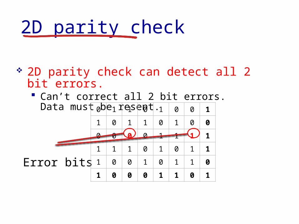
2D parity check
2D parity check can detect all 3 bit errors Canrsquot correct all 3 bit errors Data must be
resent
Error bits
0 1 1 0 1 0 0 1
1 0 1 1 0 1 0 0
0 0 0 0 1 1 1 1
1 1 0 0 1 0 1 1
1 0 0 1 0 1 1 0
1 0 0 0 1 1 0 1
2D parity check
2D parity check can detect most 4 bit errors Canrsquot correct all 4 bit errors Data must be
resent Example of a 4 bit error that is NOT
detected
Error bits
0 1 1 0 1 0 0 1
1 0 1 1 0 1 0 0
0 0 0 0 1 1 1 1
1 1 0 0 1 0 0 1
1 0 0 1 0 1 1 0
1 0 0 0 1 1 0 1
Link Layer 5-31
Internet checksum (review)
sender treat segment
contents as sequence of 16-bit integers
checksum addition (1rsquos complement sum) of segment contents
sender puts checksum value into UDP checksum field
receiver compute checksum of
received segment check if computed
checksum equals checksum field value NO - error detected YES - no error
detected But maybe errors nonetheless
goal detect ldquoerrorsrdquo (eg flipped bits) in transmitted packet (note used at transport layer only)
Link Layer 5-32
Cyclic redundancy check more powerful error-detection coding view data bits D as a binary number choose r+1 bit pattern (generator) G goal choose r CRC bits R such that
ltDRgt exactly divisible by G (modulo 2) receiver knows G divides ltDRgt by G If non-zero
remainder error detected can detect all burst errors less than r+1 bits
widely used in practice (Ethernet 80211 WiFi ATM)
Link Layer 5-33
Link layer LANs outline
51 introduction services
52 error detection correction
53 multiple access protocols
54 LANs addressing ARP Ethernet switches VLANS
55 link virtualization MPLS
56 data center networking
57 a day in the life of a web request
Link Layer 5-34
Multiple access links protocols
Two types of ldquolinksrdquo Point-to-point
PPP for dial-up access Point-to-point link between Ethernet switch host
Broadcast (shared wire or medium) Old-fashioned Ethernet Upstream HFC 80211 wireless LAN
shared wire (eg cabled Ethernet)
shared RF (eg 80211 WiFi)
shared RF(satellite)
humans at acocktail party
(shared air acoustical)
Link Layer 5-35
Multiple access protocols Single shared broadcast channel Two or more simultaneous transmissions by nodes
interference Collision if node receives two or more signals at the
same time
Multiple access protocol Distributed algorithm that determines how nodes share
channel ie determine when node can transmit Communication about channel sharing must use
channel itself No out-of-band channel for coordination
Link Layer 5-36
An ideal multiple access protocol
Given broadcast channel of rate R bps Desirable characteristics
1 When one node wants to transmit it can send at rate R2 When M nodes want to transmit each can send at average rate RM3 Fully decentralizedbull No special node to coordinate transmissionsbull No synchronization of clocks slots
4 Simple
Link Layer 5-37
MAC protocols taxonomy
Three broad classes Channel partitioning
Divide channel into smaller ldquopiecesrdquo (time slots frequency code)
Allocate piece to node for exclusive use FDMA TDMA CDMA
Random access Channel not divided allow collisions ldquoRecoverrdquo from collisions Ethernet
ldquoTaking turnsrdquo Nodes take turns but nodes with more to send can take longer
turns Token ring
Link Layer 5-38
Channel partitioning MAC protocols TDMA
TDMA time division multiple access Access to channel in rounds Each station gets fixed length slot (length = pkt
trans time) in each round Unused slots go idle Example
6-station LAN 134 have pkt slots 256 idle
1 3 4 1 3 4
6-slotframe
6-slotframe
Link Layer 5-39
FDMA frequency division multiple access Channel spectrum divided into frequency bands Each station assigned fixed frequency band Unused transmission time in frequency bands
go idle Example
6-station LAN 134 have pkt frequency bands 256 idle
freq
uenc
y ba
nds
time
FDM cable
Channel partitioning MAC protocols FDMA
Link Layer 5-40
Random access protocols When node has packet to send
Transmit at full channel data rate R No coordination among nodes
Two or more transmitting nodes ldquocollisionrdquo Random access MAC protocol specifies
How to detect collisions How to recover from collisions (eg via delayed
retransmissions) Examples of random access MAC protocols
ALOHA Slotted ALOHA CSMA CSMACD CSMACA
Link Layer 5-41
ALOHA
Aloha Norm Abramson (1969-1970) First radio packet network connecting the
Hawaiian Islands Two channels (different frequencies)
bull Downlink transmission from central host to secondary hosts
bull Uplink transmission from secondary host to central host
Important communication protocolbull First radio packet network decades before Wi-Fi
WiMAX Cellularbull Inspired CSMACD protocol used extensively by
8023 Ethernet
Link Layer 5-42
ALOHA Aloha simple no synchronization When frame first arrives
Transmit immediately High collision probability with multiple nodes
transmitting frame sent at t0 collides with other frames sent
in [t0-1t0+1]
Link Layer 5-43
ALOHA efficiencyP(success by given node) = P(node transmits)
P(no other node transmits in [t0-1t0]
P(no other node transmits in [t0-1t0]
= p (1-p)N-1 (1-p)N-1
= p (1-p)2(N-1)
hellip choosing optimum p and then letting n
= 1(2e) = 18
ALOHA bandwidth efficiency only 18Ex 18 Mbps max throughput over 100 Mbps link with multiple nodes
Link Layer 5-44
Slotted ALOHA
Assumptions all frames same size Time divided into equal size slots (time to transmit 1
frame) Nodes transmit only at the beginning of each slot Nodes are synchronized for slot timing not frame
transmission If 2 or more nodes transmit in slot all nodes detect
collision
Link Layer 5-45
Slotted ALOHA
Operation When node obtains fresh frame transmits in next slot
If no collision node can send new frame in next slot If collision node retransmits frame in each
subsequent slot with probability p until success
Link Layer 5-46
Pros single active node can
continuously transmit at full rate of channel
highly decentralized only slots in nodes need to be in sync
simple
Cons collisions wasting slots idle slots nodes may be able to
detect collision in less than time to transmit packet
clock synchronization
Slotted ALOHA1 1 1 1
2
3
2 2
3 3
node 1
node 2
node 3
C C CS S SE E E
Link Layer 5-47
Suppose N nodes with many frames to send each transmits in slot with probability p
Prob that given node has success in a slot = p(1-p)N-1
Prob that any node has a success = Np(1-p)N-1
Max efficiency find p that maximizes Np(1-p)N-1
For many nodes take limit of Np(1-p)N-1 as N goes to infinity gives
Max efficiency = 1e = 37
Efficiency long-run fraction of successful slots (many nodes all with many frames to send)
Best channel used for useful transmissions 37 of time
Better than unslotted ALOHA
Slotted ALOHA efficiency
Link Layer 5-48
CSMA (carrier sense multiple access)
CSMA listen before transmit If channel sensed is idle
Transmit entire frame If channel sensed is busy
Defer transmission
Human analogy donrsquot interrupt others
Link Layer 5-49
CSMA collisions Collisions can still occur
Propagation delay means two nodes may not hear each otherrsquos transmission
Collision Entire packet
transmission time wasted Distance amp propagation
delay play role in in determining collision probability
spatial layout of nodes
Link Layer 5-50
CSMACD (collision detection)
CSMACD Carrier Sense Multiple AccessCollision Detection Collisions detected within short time Colliding transmissions aborted reducing channel
wastage
Collision detection Easy in wired LANs measure signal strengths
compare transmitted received signals Difficult in wireless LANs received signal strength
overwhelmed by local transmission strength
Link Layer 5-51
CSMACD (collision detection)
spatial layout of nodes
Link Layer 5-52
Ethernet CSMACD algorithm1 NIC receives datagram from network layer creates
frame
2 If NIC senses channel idle starts frame transmission If NIC senses channel busy waits until channel idle then transmits
3 If NIC transmits entire frame without detecting another transmission NIC is done with frame
4 If NIC detects another transmission while transmitting aborts and sends jam signal
5 After aborting NIC enters binary (exponential) backoff state After mth collision NIC chooses K at random from 012 hellip
2m-1 NIC waits K512 bit times returns to Step 2 longer backoff intervals with more collisions
Link Layer 5-53
CSMACD efficiency
Tprop = max prop delay between 2 nodes in LAN ttrans = time to transmit max-size frame
Efficiency goes to 1 as tprop goes to 0 as ttrans goes to infinity
Better performance than ALOHA Also simple cheap and decentralized
transprop ttefficiency
51
1
Link Layer 5-54
ldquoTaking turnsrdquo MAC protocols
Channel partitioning MAC protocols Share channel efficiently and fairly at high
load Inefficient at low load delay in channel
access 1N bandwidth allocated even if only 1 active node
Random access MAC protocols Efficient at low load single node can fully
utilize channel High load collision overhead
ldquoTaking turnsrdquo protocols Look for best of both worlds
Link Layer 5-55
Polling Master node ldquoinvitesrdquo slave
nodes to transmit in turn Typically used with ldquodumbrdquo
slave devices Concerns
bull Polling overhead bull Latencybull Single point of failure
(master)
master
slaves
poll
data
data
ldquoTaking turnsrdquo MAC protocols
Link Layer 5-56
Token passing Control token passed from
one node to next sequentially Token message Concerns
Token overhead Latency Single point of failure
(token)
T
data
(nothingto send)
T
ldquoTaking turnsrdquo MAC protocols
cable headend
CMTS
ISP
cable modemtermination system
Multiple downstream (broadcast) channels Multiple upstream channels Multiple access all users contend for certain upstream
channel time slots (others assigned)
Cable access network
cablemodem
splitter
hellip
hellip
Internet framesTV channels control transmitted downstream at different frequencies
upstream Internet frames TV control transmitted upstream at different frequencies in time slots
Link Layer 5-58
Summary of MAC protocols
Channel partitioning By time frequency or code Time Division Frequency Division
Random access (dynamic) ALOHA S-ALOHA CSMA CSMACD Carrier sensing
Easy in some technologies (wire) hard in others (wireless) CSMACD used in Ethernet CSMACA used in 80211
Taking turns Polling from central site token passing Bluetooth FDDI token ring
- Slide 1
- Chapter 5 Link layer
- Link layer LANs outline
- Link layer introduction
- Link layer introduction (2)
- Link layer context
- Link layer context (2)
- Link layer services
- Link layer services (more)
- Link layer services (more) (2)
- Where is the link layer implemented
- Where is the link layer implemented (2)
- Adaptors communicating
- Link layer LANs outline (2)
- Error detection
- Error detection (2)
- Error Detection and Correction
- Problem with the simple approach
- Calculating bit string parity
- Parity check code
- 2D parity check code
- 2D parity check
- 2D parity check (2)
- 2D parity check (3)
- 2D parity check (4)
- 2D parity check (5)
- 2D parity check (6)
- 2D parity check (7)
- 2D parity check (8)
- 2D parity check (9)
- Internet checksum (review)
- Cyclic redundancy check
- Link layer LANs outline (3)
- Multiple access links protocols
- Multiple access protocols
- An ideal multiple access protocol
- MAC protocols taxonomy
- Channel partitioning MAC protocols TDMA
- Channel partitioning MAC protocols FDMA
- Random access protocols
- ALOHA
- ALOHA (2)
- ALOHA efficiency
- Slotted ALOHA
- Slotted ALOHA (2)
- Slotted ALOHA (3)
- Slotted ALOHA efficiency
- CSMA (carrier sense multiple access)
- CSMA collisions
- CSMACD (collision detection)
- CSMACD (collision detection) (2)
- Ethernet CSMACD algorithm
- CSMACD efficiency
- ldquoTaking turnsrdquo MAC protocols
- ldquoTaking turnsrdquo MAC protocols (2)
- ldquoTaking turnsrdquo MAC protocols (3)
- Slide 57
- Summary of MAC protocols
-
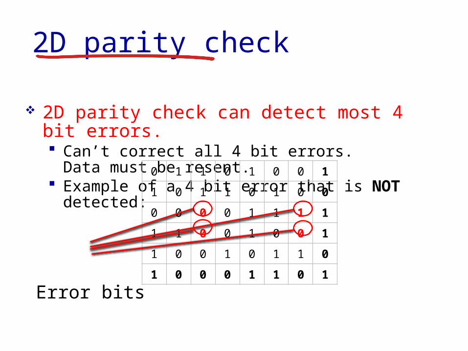
2D parity check
2D parity check can detect most 4 bit errors Canrsquot correct all 4 bit errors Data must be
resent Example of a 4 bit error that is NOT
detected
Error bits
0 1 1 0 1 0 0 1
1 0 1 1 0 1 0 0
0 0 0 0 1 1 1 1
1 1 0 0 1 0 0 1
1 0 0 1 0 1 1 0
1 0 0 0 1 1 0 1
Link Layer 5-31
Internet checksum (review)
sender treat segment
contents as sequence of 16-bit integers
checksum addition (1rsquos complement sum) of segment contents
sender puts checksum value into UDP checksum field
receiver compute checksum of
received segment check if computed
checksum equals checksum field value NO - error detected YES - no error
detected But maybe errors nonetheless
goal detect ldquoerrorsrdquo (eg flipped bits) in transmitted packet (note used at transport layer only)
Link Layer 5-32
Cyclic redundancy check more powerful error-detection coding view data bits D as a binary number choose r+1 bit pattern (generator) G goal choose r CRC bits R such that
ltDRgt exactly divisible by G (modulo 2) receiver knows G divides ltDRgt by G If non-zero
remainder error detected can detect all burst errors less than r+1 bits
widely used in practice (Ethernet 80211 WiFi ATM)
Link Layer 5-33
Link layer LANs outline
51 introduction services
52 error detection correction
53 multiple access protocols
54 LANs addressing ARP Ethernet switches VLANS
55 link virtualization MPLS
56 data center networking
57 a day in the life of a web request
Link Layer 5-34
Multiple access links protocols
Two types of ldquolinksrdquo Point-to-point
PPP for dial-up access Point-to-point link between Ethernet switch host
Broadcast (shared wire or medium) Old-fashioned Ethernet Upstream HFC 80211 wireless LAN
shared wire (eg cabled Ethernet)
shared RF (eg 80211 WiFi)
shared RF(satellite)
humans at acocktail party
(shared air acoustical)
Link Layer 5-35
Multiple access protocols Single shared broadcast channel Two or more simultaneous transmissions by nodes
interference Collision if node receives two or more signals at the
same time
Multiple access protocol Distributed algorithm that determines how nodes share
channel ie determine when node can transmit Communication about channel sharing must use
channel itself No out-of-band channel for coordination
Link Layer 5-36
An ideal multiple access protocol
Given broadcast channel of rate R bps Desirable characteristics
1 When one node wants to transmit it can send at rate R2 When M nodes want to transmit each can send at average rate RM3 Fully decentralizedbull No special node to coordinate transmissionsbull No synchronization of clocks slots
4 Simple
Link Layer 5-37
MAC protocols taxonomy
Three broad classes Channel partitioning
Divide channel into smaller ldquopiecesrdquo (time slots frequency code)
Allocate piece to node for exclusive use FDMA TDMA CDMA
Random access Channel not divided allow collisions ldquoRecoverrdquo from collisions Ethernet
ldquoTaking turnsrdquo Nodes take turns but nodes with more to send can take longer
turns Token ring
Link Layer 5-38
Channel partitioning MAC protocols TDMA
TDMA time division multiple access Access to channel in rounds Each station gets fixed length slot (length = pkt
trans time) in each round Unused slots go idle Example
6-station LAN 134 have pkt slots 256 idle
1 3 4 1 3 4
6-slotframe
6-slotframe
Link Layer 5-39
FDMA frequency division multiple access Channel spectrum divided into frequency bands Each station assigned fixed frequency band Unused transmission time in frequency bands
go idle Example
6-station LAN 134 have pkt frequency bands 256 idle
freq
uenc
y ba
nds
time
FDM cable
Channel partitioning MAC protocols FDMA
Link Layer 5-40
Random access protocols When node has packet to send
Transmit at full channel data rate R No coordination among nodes
Two or more transmitting nodes ldquocollisionrdquo Random access MAC protocol specifies
How to detect collisions How to recover from collisions (eg via delayed
retransmissions) Examples of random access MAC protocols
ALOHA Slotted ALOHA CSMA CSMACD CSMACA
Link Layer 5-41
ALOHA
Aloha Norm Abramson (1969-1970) First radio packet network connecting the
Hawaiian Islands Two channels (different frequencies)
bull Downlink transmission from central host to secondary hosts
bull Uplink transmission from secondary host to central host
Important communication protocolbull First radio packet network decades before Wi-Fi
WiMAX Cellularbull Inspired CSMACD protocol used extensively by
8023 Ethernet
Link Layer 5-42
ALOHA Aloha simple no synchronization When frame first arrives
Transmit immediately High collision probability with multiple nodes
transmitting frame sent at t0 collides with other frames sent
in [t0-1t0+1]
Link Layer 5-43
ALOHA efficiencyP(success by given node) = P(node transmits)
P(no other node transmits in [t0-1t0]
P(no other node transmits in [t0-1t0]
= p (1-p)N-1 (1-p)N-1
= p (1-p)2(N-1)
hellip choosing optimum p and then letting n
= 1(2e) = 18
ALOHA bandwidth efficiency only 18Ex 18 Mbps max throughput over 100 Mbps link with multiple nodes
Link Layer 5-44
Slotted ALOHA
Assumptions all frames same size Time divided into equal size slots (time to transmit 1
frame) Nodes transmit only at the beginning of each slot Nodes are synchronized for slot timing not frame
transmission If 2 or more nodes transmit in slot all nodes detect
collision
Link Layer 5-45
Slotted ALOHA
Operation When node obtains fresh frame transmits in next slot
If no collision node can send new frame in next slot If collision node retransmits frame in each
subsequent slot with probability p until success
Link Layer 5-46
Pros single active node can
continuously transmit at full rate of channel
highly decentralized only slots in nodes need to be in sync
simple
Cons collisions wasting slots idle slots nodes may be able to
detect collision in less than time to transmit packet
clock synchronization
Slotted ALOHA1 1 1 1
2
3
2 2
3 3
node 1
node 2
node 3
C C CS S SE E E
Link Layer 5-47
Suppose N nodes with many frames to send each transmits in slot with probability p
Prob that given node has success in a slot = p(1-p)N-1
Prob that any node has a success = Np(1-p)N-1
Max efficiency find p that maximizes Np(1-p)N-1
For many nodes take limit of Np(1-p)N-1 as N goes to infinity gives
Max efficiency = 1e = 37
Efficiency long-run fraction of successful slots (many nodes all with many frames to send)
Best channel used for useful transmissions 37 of time
Better than unslotted ALOHA
Slotted ALOHA efficiency
Link Layer 5-48
CSMA (carrier sense multiple access)
CSMA listen before transmit If channel sensed is idle
Transmit entire frame If channel sensed is busy
Defer transmission
Human analogy donrsquot interrupt others
Link Layer 5-49
CSMA collisions Collisions can still occur
Propagation delay means two nodes may not hear each otherrsquos transmission
Collision Entire packet
transmission time wasted Distance amp propagation
delay play role in in determining collision probability
spatial layout of nodes
Link Layer 5-50
CSMACD (collision detection)
CSMACD Carrier Sense Multiple AccessCollision Detection Collisions detected within short time Colliding transmissions aborted reducing channel
wastage
Collision detection Easy in wired LANs measure signal strengths
compare transmitted received signals Difficult in wireless LANs received signal strength
overwhelmed by local transmission strength
Link Layer 5-51
CSMACD (collision detection)
spatial layout of nodes
Link Layer 5-52
Ethernet CSMACD algorithm1 NIC receives datagram from network layer creates
frame
2 If NIC senses channel idle starts frame transmission If NIC senses channel busy waits until channel idle then transmits
3 If NIC transmits entire frame without detecting another transmission NIC is done with frame
4 If NIC detects another transmission while transmitting aborts and sends jam signal
5 After aborting NIC enters binary (exponential) backoff state After mth collision NIC chooses K at random from 012 hellip
2m-1 NIC waits K512 bit times returns to Step 2 longer backoff intervals with more collisions
Link Layer 5-53
CSMACD efficiency
Tprop = max prop delay between 2 nodes in LAN ttrans = time to transmit max-size frame
Efficiency goes to 1 as tprop goes to 0 as ttrans goes to infinity
Better performance than ALOHA Also simple cheap and decentralized
transprop ttefficiency
51
1
Link Layer 5-54
ldquoTaking turnsrdquo MAC protocols
Channel partitioning MAC protocols Share channel efficiently and fairly at high
load Inefficient at low load delay in channel
access 1N bandwidth allocated even if only 1 active node
Random access MAC protocols Efficient at low load single node can fully
utilize channel High load collision overhead
ldquoTaking turnsrdquo protocols Look for best of both worlds
Link Layer 5-55
Polling Master node ldquoinvitesrdquo slave
nodes to transmit in turn Typically used with ldquodumbrdquo
slave devices Concerns
bull Polling overhead bull Latencybull Single point of failure
(master)
master
slaves
poll
data
data
ldquoTaking turnsrdquo MAC protocols
Link Layer 5-56
Token passing Control token passed from
one node to next sequentially Token message Concerns
Token overhead Latency Single point of failure
(token)
T
data
(nothingto send)
T
ldquoTaking turnsrdquo MAC protocols
cable headend
CMTS
ISP
cable modemtermination system
Multiple downstream (broadcast) channels Multiple upstream channels Multiple access all users contend for certain upstream
channel time slots (others assigned)
Cable access network
cablemodem
splitter
hellip
hellip
Internet framesTV channels control transmitted downstream at different frequencies
upstream Internet frames TV control transmitted upstream at different frequencies in time slots
Link Layer 5-58
Summary of MAC protocols
Channel partitioning By time frequency or code Time Division Frequency Division
Random access (dynamic) ALOHA S-ALOHA CSMA CSMACD Carrier sensing
Easy in some technologies (wire) hard in others (wireless) CSMACD used in Ethernet CSMACA used in 80211
Taking turns Polling from central site token passing Bluetooth FDDI token ring
- Slide 1
- Chapter 5 Link layer
- Link layer LANs outline
- Link layer introduction
- Link layer introduction (2)
- Link layer context
- Link layer context (2)
- Link layer services
- Link layer services (more)
- Link layer services (more) (2)
- Where is the link layer implemented
- Where is the link layer implemented (2)
- Adaptors communicating
- Link layer LANs outline (2)
- Error detection
- Error detection (2)
- Error Detection and Correction
- Problem with the simple approach
- Calculating bit string parity
- Parity check code
- 2D parity check code
- 2D parity check
- 2D parity check (2)
- 2D parity check (3)
- 2D parity check (4)
- 2D parity check (5)
- 2D parity check (6)
- 2D parity check (7)
- 2D parity check (8)
- 2D parity check (9)
- Internet checksum (review)
- Cyclic redundancy check
- Link layer LANs outline (3)
- Multiple access links protocols
- Multiple access protocols
- An ideal multiple access protocol
- MAC protocols taxonomy
- Channel partitioning MAC protocols TDMA
- Channel partitioning MAC protocols FDMA
- Random access protocols
- ALOHA
- ALOHA (2)
- ALOHA efficiency
- Slotted ALOHA
- Slotted ALOHA (2)
- Slotted ALOHA (3)
- Slotted ALOHA efficiency
- CSMA (carrier sense multiple access)
- CSMA collisions
- CSMACD (collision detection)
- CSMACD (collision detection) (2)
- Ethernet CSMACD algorithm
- CSMACD efficiency
- ldquoTaking turnsrdquo MAC protocols
- ldquoTaking turnsrdquo MAC protocols (2)
- ldquoTaking turnsrdquo MAC protocols (3)
- Slide 57
- Summary of MAC protocols
-
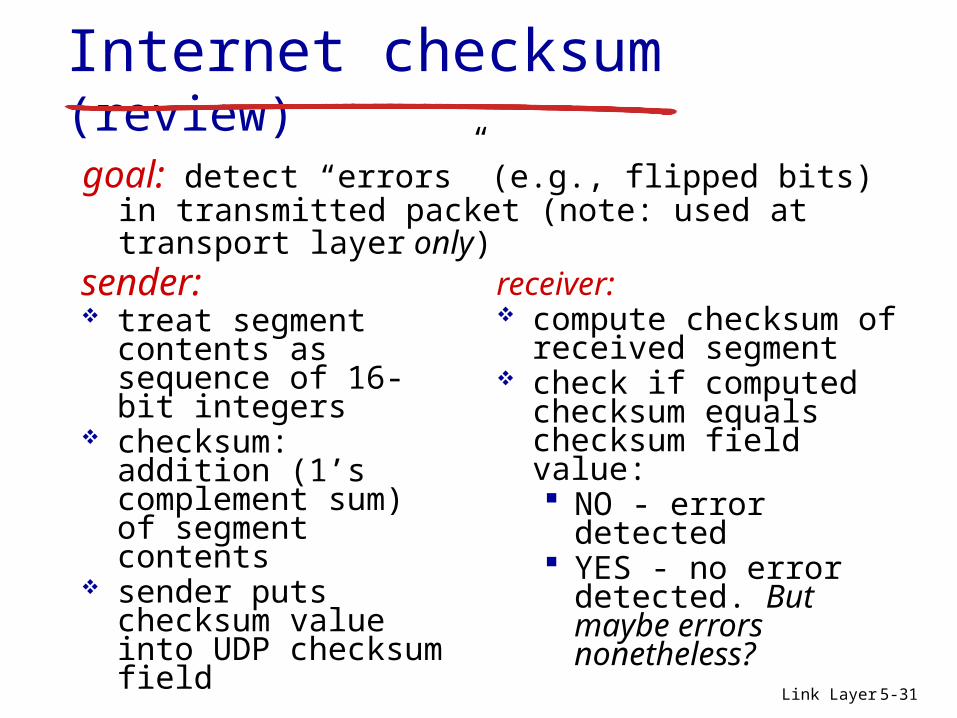
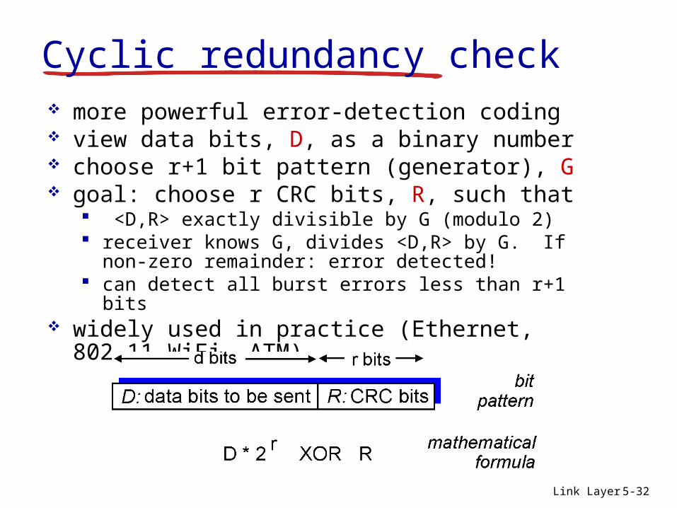
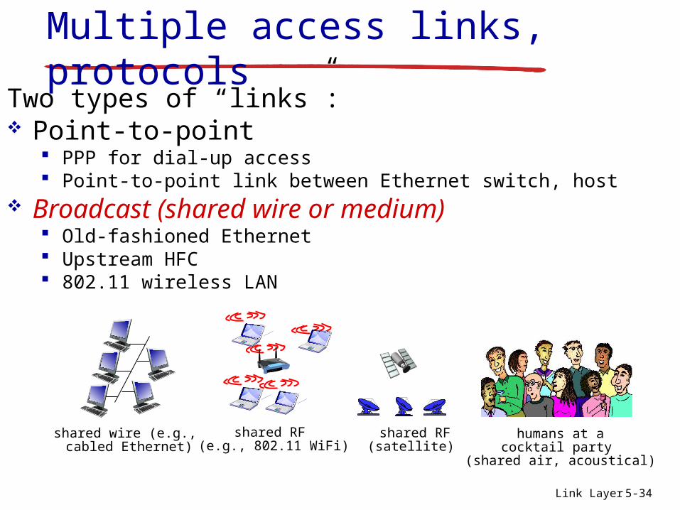
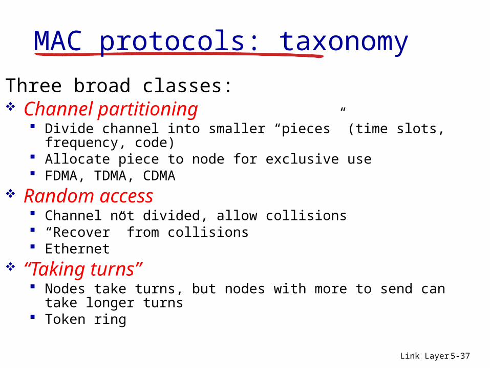
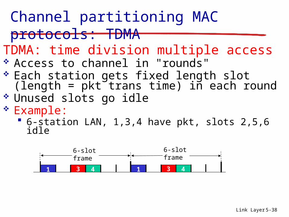
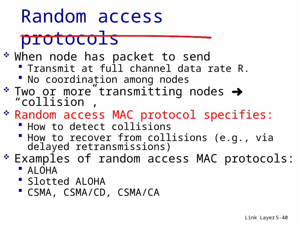
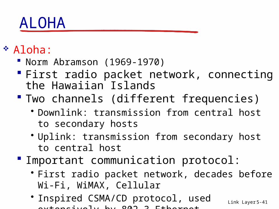
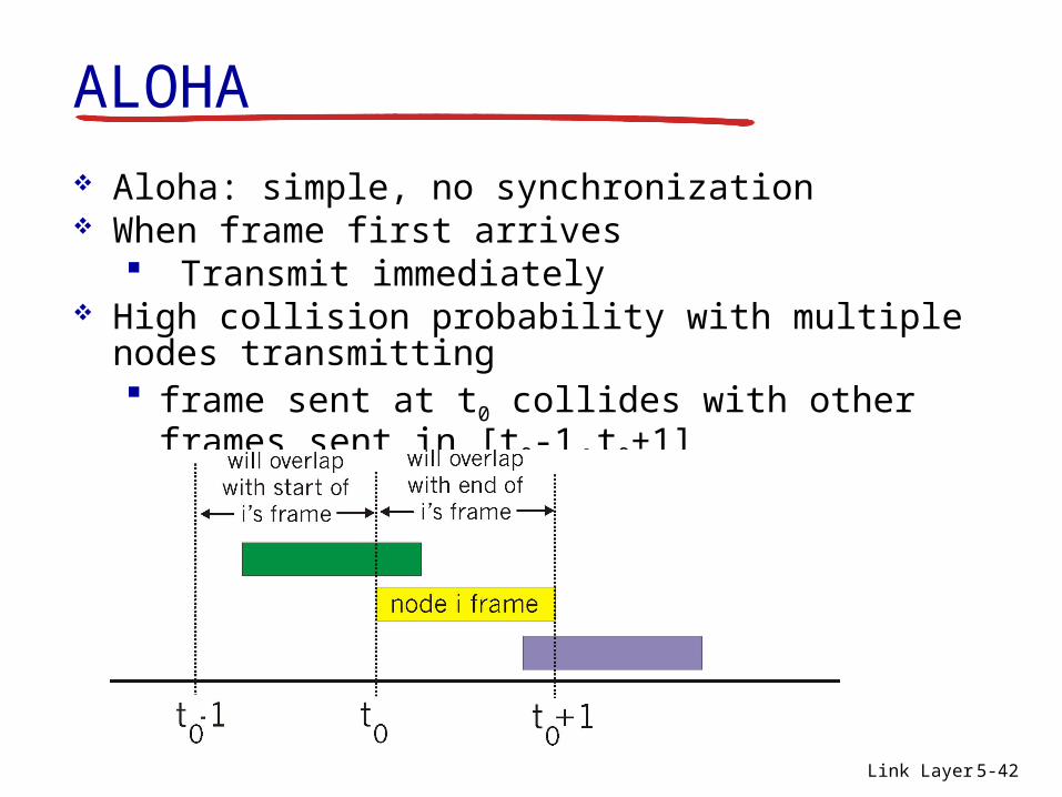
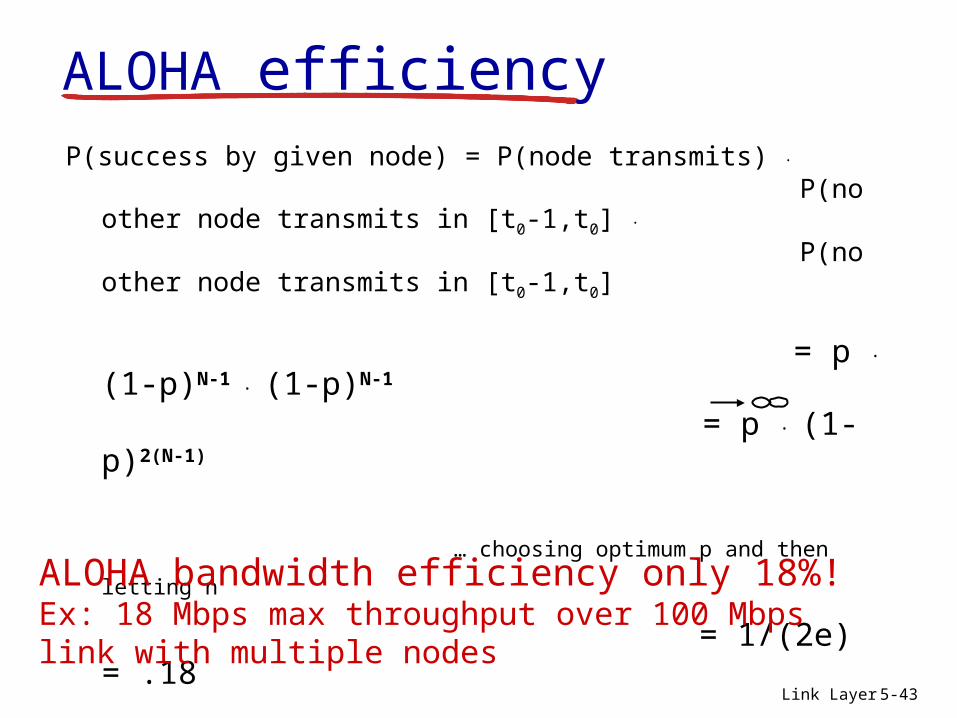
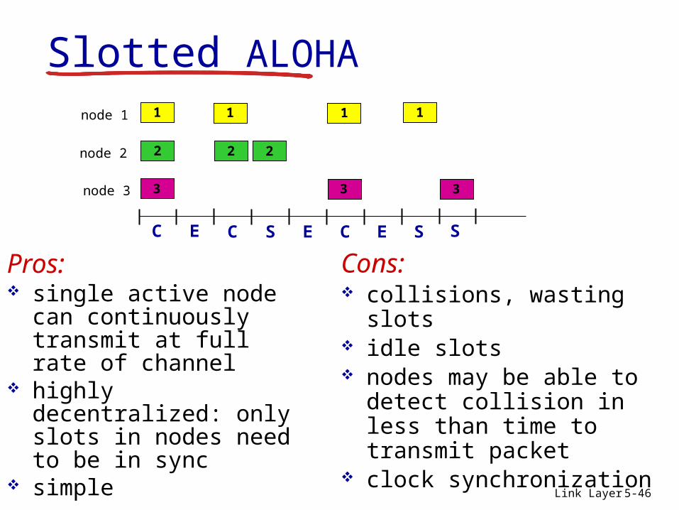
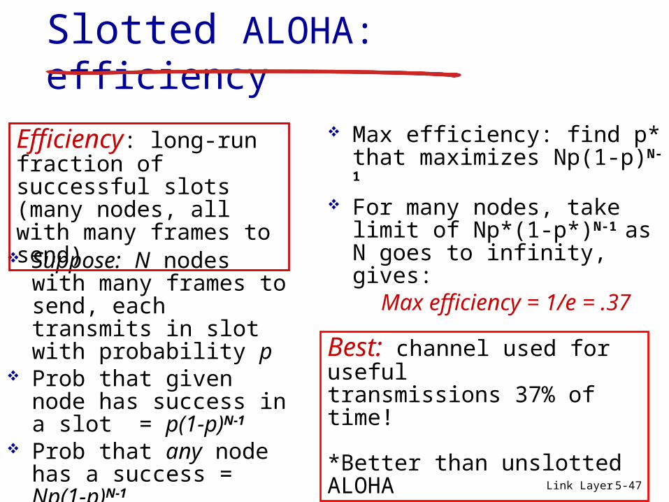
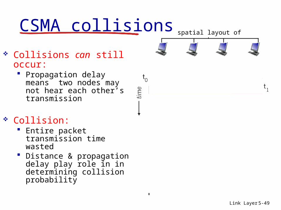
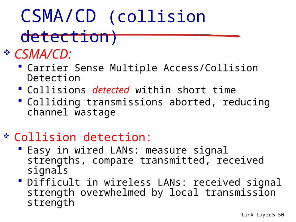
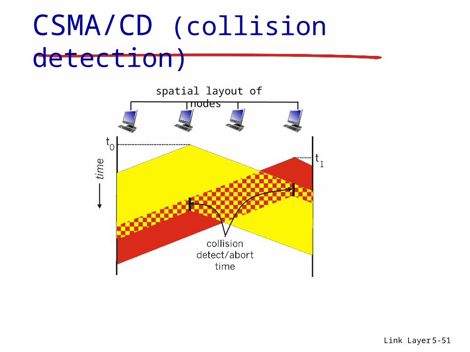
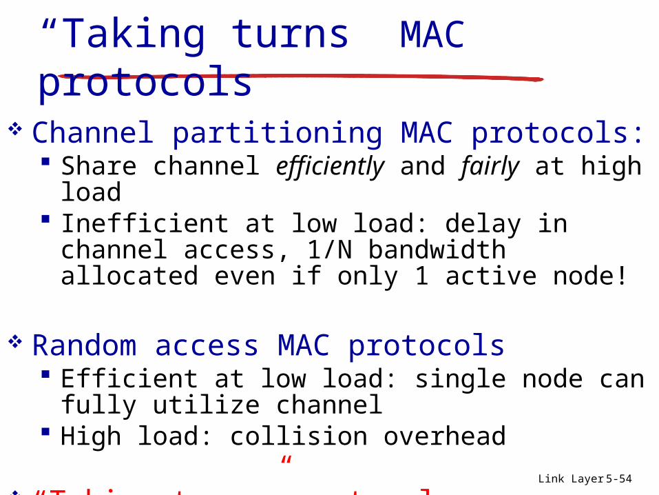
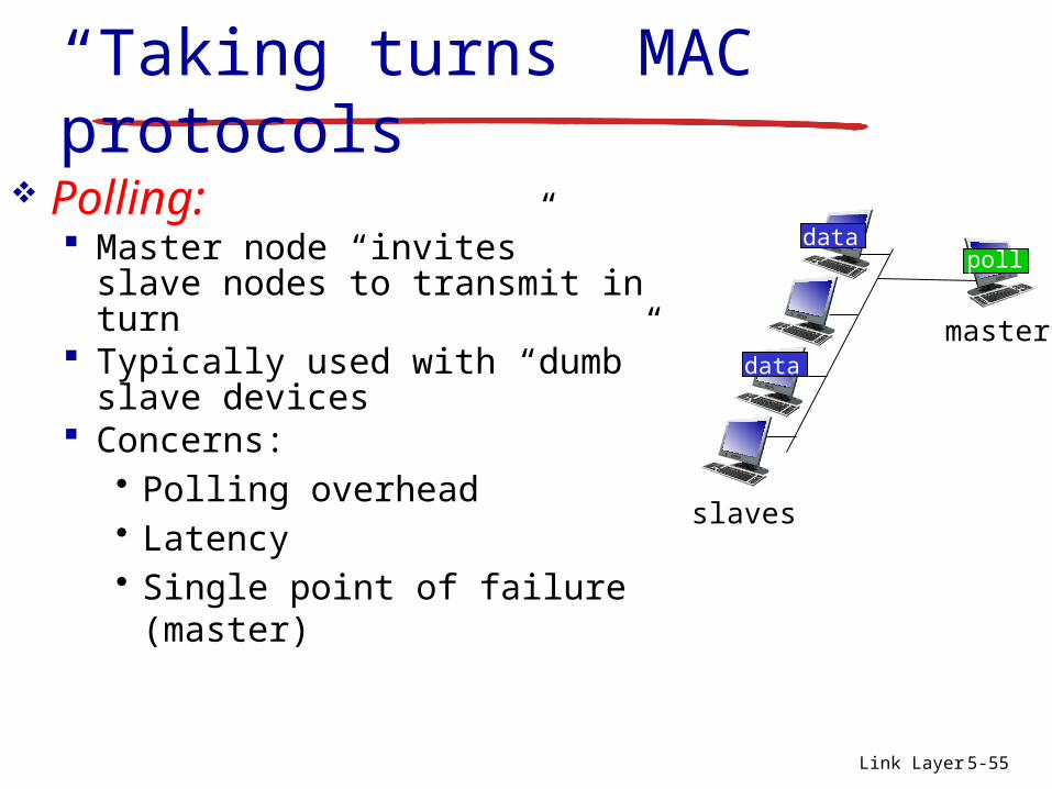
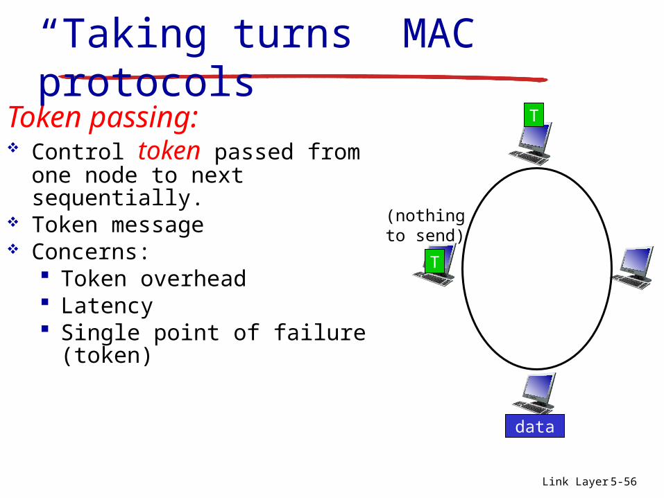
Related Documents


