4-1 CHAPTER 4 SLOW RATE PROCESS DESIGN 4.1 Introduction The key elements in the design of slow rate (SR) systems are indicated in Figure 4-1. Important features are: (1) the iterative nature of the procedure, and (2) the input information that must be obtained for detailed design. Determining the design hydraulic loading rate is the most important step in process design because this parameter is used to determine the land area required for the SR system. The design hydraulic loading rate is controlled by either soil permeability or nitrogen limits for typical municipal wastewater. Crop selection is usually the first design step because preapplication treatment, hydraulic and nitrogen loading rates, and storage depend to some extent on the crop. Preapplication treatment selection usually precedes determination of hydraulic loading rate because it can affect the wastewater nitrogen concentration and, therefore, the nitrogen loading. 4.2 Process Performance The mechanisms responsible for treatment and removal of wastewater constituents such as BOD, suspended solids (SS), nitrogen, phosphorus, trace elements, microorganisms, and trace organics are discussed briefly. Levels of removal achieved at various SR sites are included to show how removals are affected by loading rates, crop, and soil characteristics. Chapter 9 contains discussion on the health and environmental effects of these constituents. 4.2.1 BOD and Suspended Solids Removal BOD and SS are removed by filtration and bacterial action as the applied wastewater percolates through the soil. BOD and SS are normally reduced to concentrations of less than 2 mg/L and less than 1 mg/L, respectively, following 1.5 m (5 ft) of percolation. Typical loading rates of BOD and SS for municipal wastewater SR systems, regardless of the degree of preapplication treatment, are far below the loading rates at which performance is affected (see Section 2.2.1.1). Thus, loading rates for BOD and SS are normally not a concern in the design of SR systems . Removals of BOD achieved at five selected sites are presented in Table 4-1.

Welcome message from author
This document is posted to help you gain knowledge. Please leave a comment to let me know what you think about it! Share it to your friends and learn new things together.
Transcript

4-1
CHAPTER 4
SLOW RATE PROCESS DESIGN
4.1 Introduction
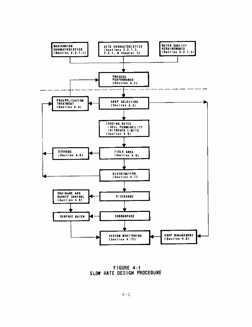
The key elements in the design of slow rate (SR) systems areindicated in Figure 4-1. Important features are: (1) theiterative nature of the procedure, and (2) the inputinformation that must be obtained for detailed design.
Determining the design hydraulic loading rate is the mostimportant step in process design because this parameter isused to determine the land area required for the SR system.The design hydraulic loading rate is controlled by eithersoil permeability or nitrogen limits for typical municipalwastewater. Crop selection is usually the first design stepbecause preapplication treatment, hydraulic and nitrogenloading rates, and storage depend to some extent on the crop.Preapplication treatment selection usually precedesdetermination of hydraulic loading rate because it can affectthe wastewater nitrogen concentration and, therefore, thenitrogen loading.
4.2 Process Performance
The mechanisms responsible for treatment and removal ofwastewater constituents such as BOD, suspended solids (SS),nitrogen, phosphorus, trace elements, microorganisms, andtrace organics are discussed briefly. Levels of removalachieved at various SR sites are included to show howremovals are affected by loading rates, crop, and soilcharacteristics. Chapter 9 contains discussion on the healthand environmental effects of these constituents.
4.2.1 BOD and Suspended Solids Removal
BOD and SS are removed by filtration and bacterial action asthe applied wastewater percolates through the soil. BOD andSS are normally reduced to concentrations of less than 2 mg/Land less than 1 mg/L, respectively, following 1.5 m (5 ft) ofpercolation. Typical loading rates of BOD and SS formunicipal wastewater SR systems, regardless of the degree ofpreapplication treatment, are far below the loading rates atwhich performance is affected (see Section 2.2.1.1). Thus,loading rates for BOD and SS are normally not a concernin the design of SR systems. Removals of BOD achievedat five selected sites are presented in Table 4-1.
4-2

4-3
TABLE 4-1BOD REMOVAL DATA
FOR SELECTED SR SYSTEMS [1-5]
4.2.2 Nitrogen
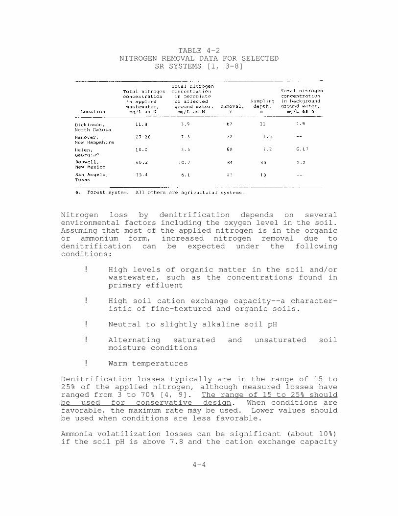
For SR systems located above potable aquifers, nitrogenconcentration in percolate must be low enough that groundwater quality at the project boundary can meet drinking waternitrate standards. Nitrogen removal mechanisms at SR systemsinclude crop uptake, nitrification-denitrification, ammoniavolatilization, and storage in the soil. Percolate nitrogenconcentrations less than 10 mg/L can be achieved with SRsystems if the nitrogen loading rate is maintained within thecombined removal rates of these mechanisms. The nitrogenremoval rates and loading rate are, therefore, importantdesign parameters. Percolate nitrogen levels achieved atselected SR sites are given in Table 4-2.
Crop uptake is normally the primary nitrogen removalmechanism operating in SR systems. The amount of nitrogenremoved by crop harvest depends on the nitrogen content ofthe crop and the crop yield. Annual nitrogen uptake ratesfor specific crops are given in Section 4.3.2.1. Maximumnitrogen removal can be achieved by selecting crops or cropcombinations with the highest nitrogen uptake potential.
4-4
TABLE 4-2NITROGEN REMOVAL DATA FOR SELECTED
SR SYSTEMS [1, 3-8]
Nitrogen loss by denitrification depends on severalenvironmental factors including the oxygen level in the soil.Assuming that most of the applied nitrogen is in the organicor ammonium form, increased nitrogen removal due todenitrification can be expected under the followingconditions:
! High levels of organic matter in the soil and/orwastewater, such as the concentrations found inprimary effluent
! High soil cation exchange capacity--a character-istic of fine-textured and organic soils.
! Neutral to slightly alkaline soil pH
! Alternating saturated and unsaturated soilmoisture conditions
! Warm temperatures
Denitrification losses typically are in the range of 15 to25% of the applied nitrogen, although measured losses haveranged from 3 to 70% [4, 9]. The range of 15 to 25% shouldbe used for conservative design. When conditions arefavorable, the maximum rate may be used. Lower values shouldbe used when conditions are less favorable.
Ammonia volatilization losses can be significant (about 10%)if the soil pH is above 7.8 and the cation exchange capacity
4-5
is low (sandy, low organic soils). For design,volatilization losses may be considered included in the 15 to25% used for denitrification.
Storage of nitrogen in the soil through plant uptake andsubsequent conversion of roots and unharvested residues intosoil humus can account for nitrogen retention rates up to 225kg/ha•yr (200 lb/acre•yr) in soils of arid regions initiallylow in organic matter (less than 2%). In contrast, nitrogenstorage will be near zero for soils rich in organic matter.In either case, if nitrogen input remains constant, the rateof nitrogen storage will decrease with time because the rateof decay and release of nitrogen increases with theconcentration of soil organic nitrogen. Eventually, anequilibrium level of organic nitrogen may be obtained and netstorage then ceases. Therefore, for design purposes, themost conservative approach is to assume net storage will bezero.
4.2.3 Phosphorus
Phosphorus is removed primarily by adsorption and pre-cipitation (together referred to as sorption) reactions inthe soil. Crop uptake can account for phosphorus removals inthe range of 20 to 60 kg/ha-yr (18 to 53 lb/acre yr),depending on the crop and yield (Section 4.3.2.1). Percolatephosphorus concentrations at several SR sites are presentedin Table 4—3.
The phosphorus sorption capacity of a soil profile depends onthe amounts of clay, aluminum, iron, and calcium compoundspresent and the soil pH. In general, fine textured mineralsoils have the highest phosphorus sorption capacities andcoarse textured acidic or organic soils have the lowest.
For systems with coarse textured soils and limits on theconcentration of percolate phosphorus, a phosphorusadsorption test should be conducted using soil from theselected site. This test, described in Section 3.7.2,determines the amount of phosphorus that the soil can removeduring short application periods. Actual phosphorusretention at an operating system will be at least 2 to 5times the value obtained during a 5 day adsorptiontest [13].

4-6

4-7
For purposes of design and operation, the soil profile can beconsidered to have a finite phosphorus sorption capacityassociated with each layer. Eventually, the sorptioncapacity of the entire soil profile may reach saturation andsoluble phosphorus will appear in the percolate. In caseswhere effluent quality requirements limit the concentrationof phosphorus in the percolate, the useful life of the SRsystem may be limited by the phosphorus sorption capacity ofthe soil profile. An empirical model to predict the usefullife of an SR system has been developed [9].
4.2.4 Trace Elements
Trace element removal in the soil is a complex processinvolving the mechanisms of adsorption, precipitation, ionexchange, and complexation. Because adsorption of most traceelements occurs on the surfaces of clay minerals, metaloxides, and organic matter, fine textured and organic soilshave a greater adsorption capacity for trace elements thansandy soils.
Removal of trace elements from solution is nearly complete insoils suitable for SR systems. Consequently, trace elementremoval is not a concern in the design procedure.Performance data from selected SR systems are presented inTable 4-4.
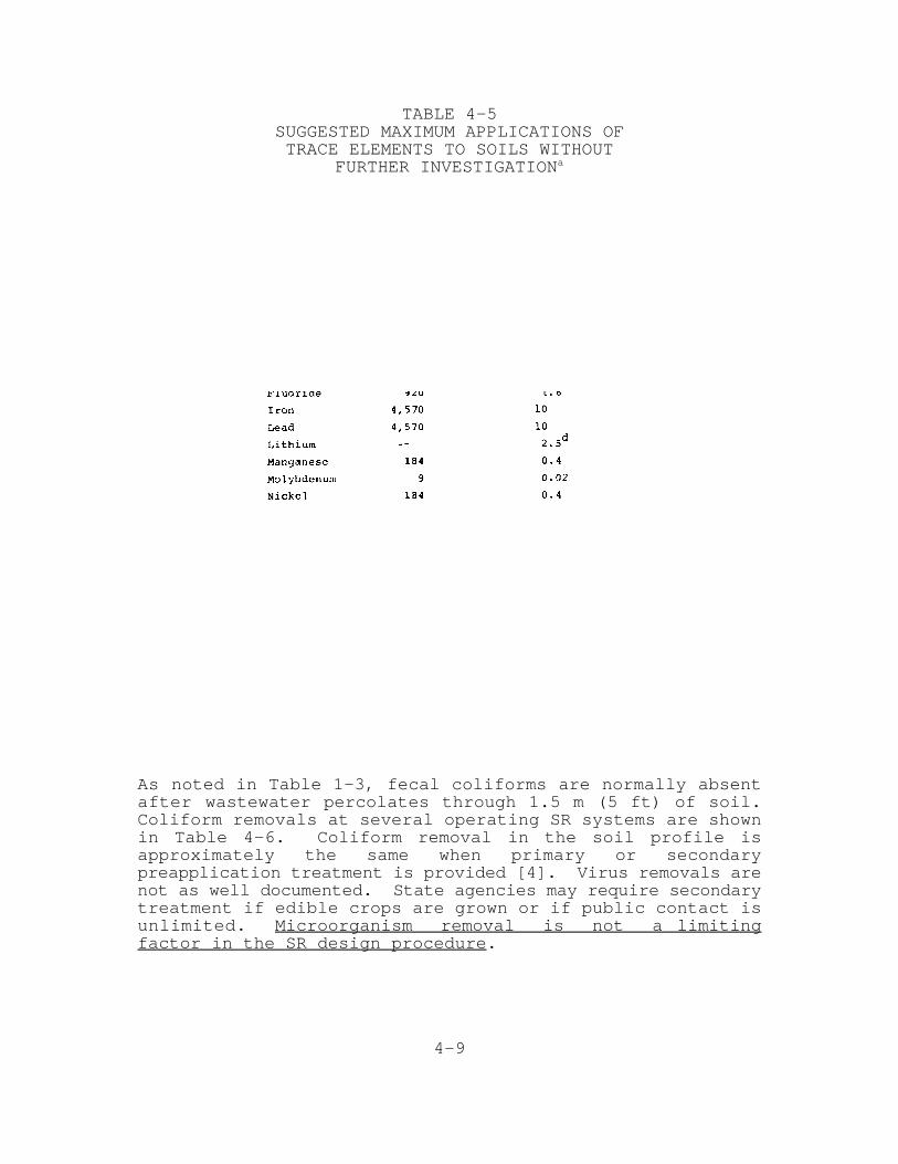
Although some trace elements can be toxic to plants andconsumers of plants, no universally accepted toxic thresholdvalues for trace element concentrations in the soil or formass additions to the soil have been established. Maximumloadings over the life of a system for several trace elementshave been suggested for soils having low trace elementretention capacities and are presented in Table 4-5.
Toxicity hazards can be minimized by maintaining the soil pHabove 6.5. Most trace elements are retained as unavailableinsoluble compounds above pH 6.5. Methods for adjusting soilpH are discussed in Section 4.9.1.3.
4.2.5 Microorganisms
Removal of microorganisms, including bacteria, viruses, andparasitic protozoa and helminths (worms), is accomplished byfiltration, adsorption, desiccation, radiation, predation,and exposure to other adverse conditions. Because of theirlarge size, protozoa and helminths are removed primarily byfiltration at the soil surface. Bacteria also are removed byfiltration at the soil surface, although adsorption may beimportant. Viruses are removed almost entirely byadsorption.

4-8
4-9
TABLE 4-5SUGGESTED MAXIMUM APPLICATIONS OFTRACE ELEMENTS TO SOILS WITHOUT
FURTHER INVESTIGATIONa
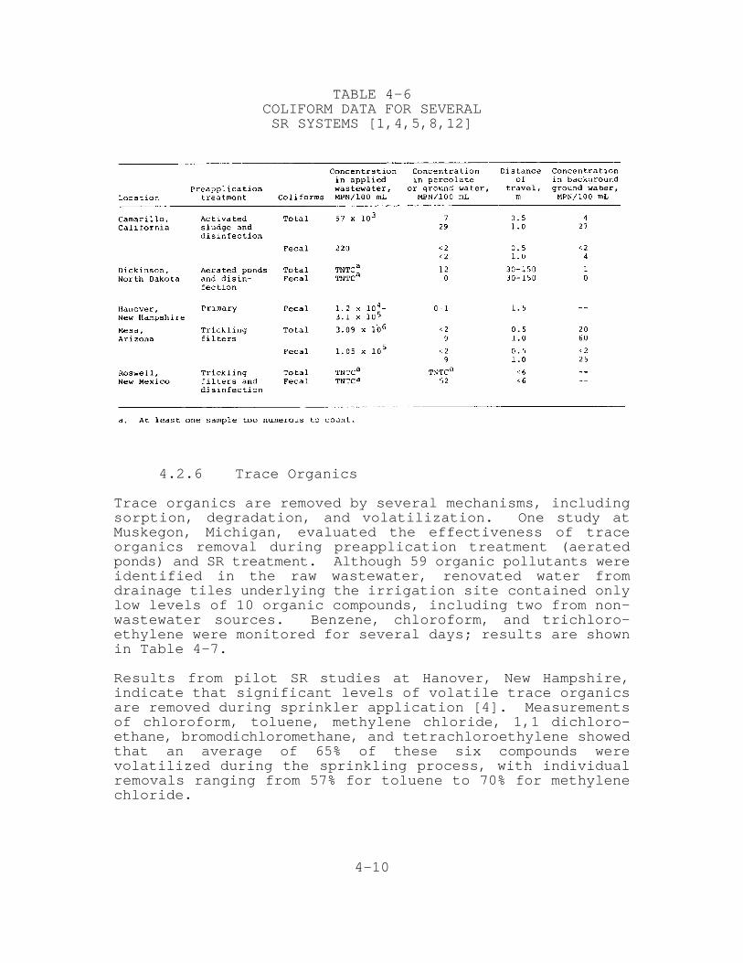
As noted in Table 1-3, fecal coliforms are normally absentafter wastewater percolates through 1.5 m (5 ft) of soil.Coliform removals at several operating SR systems are shownin Table 4-6. Coliform removal in the soil profile isapproximately the same when primary or secondarypreapplication treatment is provided [4]. Virus removals arenot as well documented. State agencies may require secondarytreatment if edible crops are grown or if public contact isunlimited. Microorganism removal is not a limitingfactor in the SR design procedure.
4-10
TABLE 4-6COLIFORM DATA FOR SEVERALSR SYSTEMS [1,4,5,8,12]
4.2.6 Trace Organics
Trace organics are removed by several mechanisms, includingsorption, degradation, and volatilization. One study atMuskegon, Michigan, evaluated the effectiveness of traceorganics removal during preapplication treatment (aeratedponds) and SR treatment. Although 59 organic pollutants wereidentified in the raw wastewater, renovated water fromdrainage tiles underlying the irrigation site contained onlylow levels of 10 organic compounds, including two from non-wastewater sources. Benzene, chloroform, and trichloro-ethylene were monitored for several days; results are shownin Table 4-7.
Results from pilot SR studies at Hanover, New Hampshire,indicate that significant levels of volatile trace organicsare removed during sprinkler application [4]. Measurementsof chloroform, toluene, methylene chloride, 1,1 dichloro-ethane, bromodichloromethane, and tetrachloroethylene showedthat an average of 65% of these six compounds werevolatilized during the sprinkling process, with individualremovals ranging from 57% for toluene to 70% for methylenechloride.

4-11
TABLE 4-7BENZENE, CHLOROFORM, AND TRICHLOROETHYLENEIN MUSKEGON WASTEWATER TREATMENT SYSTEM [17]
Based on these results, it appears that a typical SR systemis quite effective in removing trace organics. However, ifa community*s wastewater contains large concentrations oftrace organics from industrial contributions, industrialpretreatment should be considered. If hazardous chlorinatedtrace organics result from wastewater chlorination, theengineer must decide in consultation with regulatoryauthorities whether it is more important to remove pathogensor to reduce trace organic levels. This decision should takeinto consideration the type of crop and the method ofdistribution.
4.3 Crop Selection
The crop is a critical component in the SR process. Itremoves nutrients, reduces erosion, maintains or increasesinfiltration rates, and can produce revenue where marketsexist.
4.3.1 Guidelines for Crop Selection
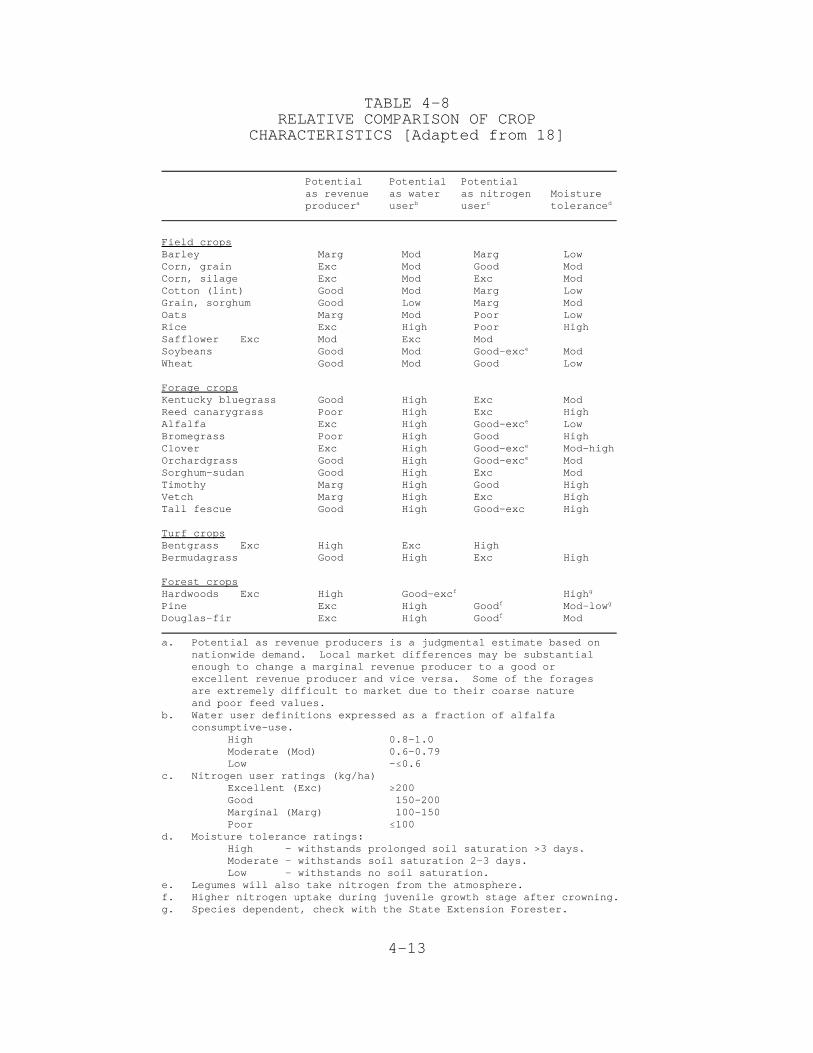
Important characteristics or properties of crops that shouldbe considered when selecting a crop for SR systems include:(1) nutrient uptake capacity, (2) tolerance to high soilmoisture conditions, (3) consumptive use of water andirrigation requirements, and (4) revenue potential. Arelative comparison of these characteristics for severaltypes of crops is presented in Table 4-8 as a general guide

4-12
to selection. Characteristics of secondary importanceinclude (1) effect on soil infiltration rate, (2) crop waterquality requirements and toxicity concerns, and (3)management requirements.
Most SR systems are designed to minimize land area by usingmaximum hydraulic loading rates. Crops that are compatiblewith high hydraulic loading rates are those having highnitrogen uptake capacity, high consumptive water use, andhigh tolerance to moist soil conditions. Other desirablecrop characteristics for this situation are low sensitivityto wastewater constituents, and minimum managementrequirements. Crops grown for revenue must have a readylocal market and be compatible with wastewater treatmentobjectives.
4.3.1.1 Agricultural Crops
Agricultural crops most compatible with the objective ofmaximum hydraulic loading are the forage and turf grasses.Forage crops that have been used successfully include: Reedcanarygrass, tall fescue, perennial ryegrass, Italianryegrass, orchardgrass, and bermudagrass. If forageutilization and value are not a consideration, Reedcanarygrass is often a first choice in its area of adaptationbecause of high nitrogen uptake rate, winter hardiness, andpersistence. However, Reed canarygrass is slow to establishand should be planted initially with a companion grass(ryegrass, orchardgrass, or tall fescue) to provide goodinitial cover.
Of the perennial grasses grown for forage utilization andrevenue under high wastewater loading rates, orchardgrass isgenerally considered to be more acceptable as animal feedthan tall fescue or Reed canarygrass. However, orchardgrassis prone to leaf diseases in the southern and eastern states.Tall fescue is generally preferred as a feed over Reedcanarygrass but is not suitable for use in the northern tierof states due to lack of winter—hardiness. Again, othercrops may be more suitable for local conditions and advice oflocal farm advisers or extension specialists will be helpfulin making the crop selection.
Corn will grow satisfactorily where the water table depth isabout 1.5 to 2 m, (5 to 7 ft) but alfalfa requires naturallywell-drained soils and water table depths of at least 3 m (10ft) for persistence. The alfalfa cultivar selected should behigh yielding with resistance to root rot and bacterial wiltin the growing region, especially when high hydraulic loadingrates (>7.5 cm/wk or 3 in./wk) are used.
4-13
TABLE 4-8RELATIVE COMPARISON OF CROP
CHARACTERISTICS [Adapted from 18]
Potential Potential Potentialas revenue as water as nitrogen Moistureproducer user user tolerancea b c d
Field cropsBarley Marg Mod Marg LowCorn, grain Exc Mod Good ModCorn, silage Exc Mod Exc ModCotton (lint) Good Mod Marg LowGrain, sorghum Good Low Marg ModOats Marg Mod Poor LowRice Exc High Poor HighSafflower Exc Mod Exc ModSoybeans Good Mod Good-exc Mode
Wheat Good Mod Good Low
Forage cropsKentucky bluegrass Good High Exc ModReed canarygrass Poor High Exc HighAlfalfa Exc High Good-exc Lowe
Bromegrass Poor High Good HighClover Exc High Good-exc Mod-highe
Orchardgrass Good High Good-exc Mode
Sorghum—sudan Good High Exc ModTimothy Marg High Good HighVetch Marg High Exc HighTall fescue Good High Good-exc High
Turf cropsBentgrass Exc High Exc HighBermudagrass Good High Exc High
Forest cropsHardwoods Exc High Good-exc Highf g
Pine Exc High Good Mod-lowf g
Douglas-fir Exc High Good Modf
a. Potential as revenue producers is a judgmental estimate based onnationwide demand. Local market differences may be substantialenough to change a marginal revenue producer to a good orexcellent revenue producer and vice versa. Some of the foragesare extremely difficult to market due to their coarse natureand poor feed values.
b. Water user definitions expressed as a fraction of alfalfa consumptive-use.
High 0.8-1.0Moderate (Mod) 0.6-0.79Low -#0.6
c. Nitrogen user ratings (kg/ha)Excellent (Exc) $200Good 150-200Marginal (Marg) 100-150Poor #100
d. Moisture tolerance ratings:High - withstands prolonged soil saturation >3 days.Moderate - withstands soil saturation 2-3 days.Low - withstands no soil saturation.
e. Legumes will also take nitrogen from the atmosphere.f. Higher nitrogen uptake during juvenile growth stage after crowning.g. Species dependent, check with the State Extension Forester.
4-14
A mixture of alfalfa and a persistent forage grass, such asorchardgrass, can be used on soils that are not naturallywell drained. At high hydraulic loading rates, the alfalfamay not persist over 2 years, but the forage grass will fillin the areas in the thinned alfalfa stand.
The most common agricultural crops grown for revenue usingwastewater are corn (silage), alfalfa (silage, hay, orpasture), forage grass (silage, hay, or pasture), grainsorghum, cotton, and grains [18]. However, any crop,including food crops, may be grown with reclaimed wastewaterafter suitable preapplication treatment.
In areas with a long growing season, such as California,selection of a double crop is an excellent means ofincreasing the revenue potential as well as the annualconsumptive water use and nitrogen uptake of the crop system.Double crop combinations that are commonly used include (1)short season varieties of soybeans, silage corn, or sorghumas a summer crop; and (2) barley, oats, wheat, vetch, orannual forage grass as a winter crop.
A growing practice in the East and Midwest is to provide acontinuous vegetative cover with grass and corn. This “no-till” corn management consists of planting grass in the falland then applying a herbicide in the spring before plantingthe corn. When the corn completes its growth cycle, grass isreseeded. Thus, cultivation is reduced; water use ismaximized; nutrient uptake is enhanced; and revenue potentialis increased.
4.3.1.2 Forest Crops
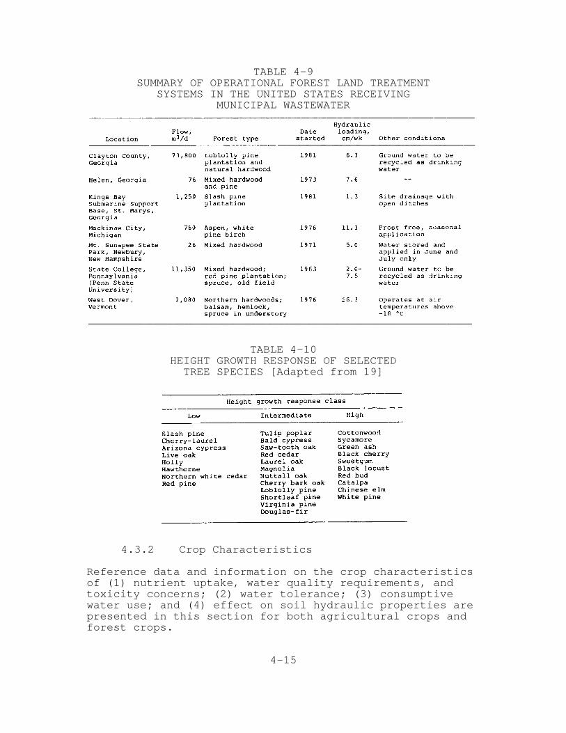
The most common forest crops used in SR systems have beenmixed hardwoods and pines. A summary of representativeoperational systems and types of forest crops used ispresented in Table 4-9.
The growth responses of a number of tree species to a rangeof wastewater loadings are identified in Table 4-10. Thehigh growth response column is most suitable for wastewaterapplication because of nitrogen uptake and productivity. Thegrowth response will vary in accordance with a number offactors; one of the most important is the adaptability of theselected species to the local climate. Local forestersshould be consulted for specific judgments on the likelyresponse of selected species.
4-15
TABLE 4-9SUMMARY OF OPERATIONAL FOREST LAND TREATMENT
SYSTEMS IN THE UNITED STATES RECEIVINGMUNICIPAL WASTEWATER
TABLE 4-10HEIGHT GROWTH RESPONSE OF SELECTEDTREE SPECIES [Adapted from 19]
4.3.2 Crop Characteristics
Reference data and information on the crop characteristicsof (1) nutrient uptake, water quality requirements, andtoxicity concerns; (2) water tolerance; (3) consumptivewater use; and (4) effect on soil hydraulic properties arepresented in this section for both agricultural crops andforest crops.

4-16
4.3.2.1 Nutrient Uptake
Agricultural Crops
In general, the largest nutrient removals can be achievedwith perennial grasses and legumes that are cut frequently atearly stages of growth. It should be recognized that legumescan fix nitrogen from the air, but they are active scavengersfor nitrate if it is present. The potential for harvestingnutrients with annual crops is generally less than withperennials because annuals use only part of the availablegrowing season for growth and active uptake. Typical annualuptake rates of the major plant nutrients--nitrogen,phosphorus, and potassium--are listed in Table 4—11 forseveral commonly selected crops.
The nutrient removal capacity of a crop is not a fixedcharacteristic but depends on the crop yield and the nutrientcontent of the plant at the time of harvest. Designestimates of harvest removals should be based on yield goalsand nutrient compositions that local experience indicates canbe achieved with good management on similar soils.
TABLE 4-11NUTRIENT UPTAKE RATES FOR
SELECTED CROPSkg/ha•yr
4-17
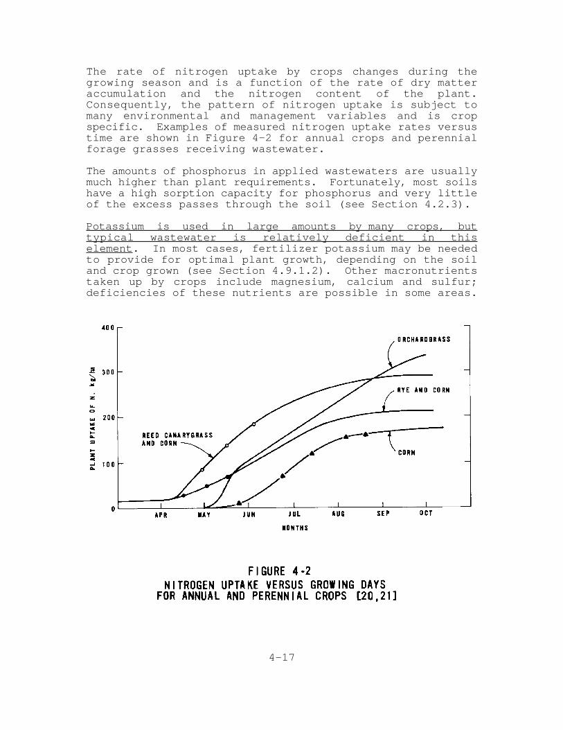
The rate of nitrogen uptake by crops changes during thegrowing season and is a function of the rate of dry matteraccumulation and the nitrogen content of the plant.Consequently, the pattern of nitrogen uptake is subject tomany environmental and management variables and is cropspecific. Examples of measured nitrogen uptake rates versustime are shown in Figure 4-2 for annual crops and perennialforage grasses receiving wastewater.
The amounts of phosphorus in applied wastewaters are usuallymuch higher than plant requirements. Fortunately, most soilshave a high sorption capacity for phosphorus and very littleof the excess passes through the soil (see Section 4.2.3).
Potassium is used in large amounts by many crops, buttypical wastewater is relatively deficient in thiselement. In most cases, fertilizer potassium may be neededto provide for optimal plant growth, depending on the soiland crop grown (see Section 4.9.1.2). Other macronutrientstaken up by crops include magnesium, calcium and sulfur;deficiencies of these nutrients are possible in some areas.
4-18
The micronutrients important to plant growth (in descendingorder) are: iron, manganese, zinc, boron, copper, molybdenum,and, occasionally, sodium, silicon, chloride, and cobalt.Most wastewaters contain an ample supply of these elements;in some cases, phytotoxicity may be a consideration.
Forest Crops
Vegetative uptake and storage of nutrients depend on thespecies and forest stand density, structure, age, length ofseason, and temperature. In addition to the trees, there isalso nutrient uptake and storage by the understory tree andherbaceous vegetation. The role of the understory vegetationis particularly important in the early stages of treeestablishment.
Forests take up and store nutrients and return a portion ofthose nutrients back to the soil in the form of leaf fall andother debris such as dead trees. Upon decomposition, thenutrients are released and the trees take them back up.During the initial stages of growth (1 to 2 years), treeseedlings are establishing a root system; biomass productionand nutrient uptake are relatively slow. To prevent leachingof nitrogen to ground water during this period, nitrogenloading must be limited or understory vegetation must beestablished that will take up and store applied nitrogen thatis in excess of the tree crop needs. Management ofunderstory vegetation is discussed in Section 4.9.
Following the initial growth stage, the rates of growth andnutrient uptake increase and remain relatively constant untilmaturity is approached and the rates decrease. When growthrates and nutrient uptake rates begin to decrease, the standshould be harvested or the nutrient loading decreased.Maturity may be reached at 20 to 25 years for southern pines,50 to 60 years for hardwoods, and 60 to 80 years for some ofthe western conifers such as Douglasfir. Of course,harvesting may be practiced well in advance of maturity aswith short-term rotation management (see Section 4.9.2.5).
Estimates of the net annual nitrogen storage for a number offully stocked forest ecosystems are presented in Table 4-12.These estimates are maximum rates of net nitrogen uptakeconsidering both the understory and overstory vegetationduring the period of active tree growth.

4-19
TABLE 4-12ESTIMATED NET ANNUAL NITROGEN UPTAKE IN THEOVERSTORY AND UNDERSTORY VEGETATION OF FULLY
STOCKED AND VIGOROUSLY GROWING FORESTECOSYSTEMS IN SELECTED REGIONS OF THE UNITED STATES [22]
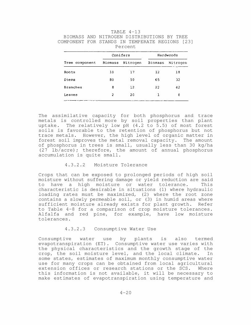
Because nitrogen stored within the biomass of trees is notuniformly distributed among the tree components, the amountof nitrogen that can actually be removed with a forest cropsystem will be substantially less than the storage estimatesgiven in Table 4-12 unless 100% of the aboveground biomass isharvested (whole—tree harvesting). If only themerchantable stems are removed from the system, the netamount of nitrogen removed by the system will be less than30% of the amount stored in the biomass. The distributionsof biomass and nitrogen for naturally growing hardwood andconifer (pines, Douglas-fir, fir, larch, etc.) stands intemperate regions are shown in Table 4-13. For deciduousspecies, whole-tree harvesting must take place in the summerwhen the leaves are on the trees if maximum nitrogen removalis to be achieved.
4-20
TABLE 4-13BIOMASS AND NITROGEN DISTRIBUTIONS BY TREE
COMPONENT FOR STANDS IN TEMPERATE REGIONS [23]Percent
The assimilative capacity for both phosphorus and tracemetals is controlled more by soil properties than plantuptake. The relatively low pH (4.2 to 5.5) of most forestsoils is favorable to the retention of phosphorus but nottrace metals. However, the high level of organic matter inforest soil improves the metal removal capacity. The amountof phosphorus in trees is small, usually less than 30 kg/ha(27 lb/acre); therefore, the amount of annual phosphorusaccumulation is quite small.
4.3.2.2 Moisture Tolerance
Crops that can be exposed to prolonged periods of high soilmoisture without suffering damage or yield reduction are saidto have a high moisture or water tolerance. Thischaracteristic is desirable in situations (1) where hydraulicloading rates must be maximized, (2) where the root zonecontains a slowly permeable soil, or (3) in humid areas wheresufficient moisture already exists for plant growth. Referto Table 4-8 for a comparison of crop moisture tolerances.Alfalfa and red pine, for example, have low moisturetolerances.
4.3.2.3 Consumptive Water Use
Consumptive water use by plants is also termedevapotranspiration (ET). Consumptive water use varies withthe physical characteristics and the growth stage of thecrop, the soil moisture level, and the local climate. Insome states, estimates of maximum monthly consumptive wateruse for many crops can be obtained from local agriculturalextension offices or research stations or the SCS. Wherethis information is not available, it will be necessary tomake estimates of evapotranspiration using temperature and

4-21
other climatic data. Several methods of estimatingevapotranspiration are available and are detailed inpublications by the American Society of Civil Engineers(ASCE) [24], the Food and Agriculture Organization (FAO) ofthe United Nations [25], and the SCS [26].
Agricultural Crops
In humid regions estimates of potential evapotranspiration(PET) are usually sufficient for perennial, full-covercrops. Examples of estimated PET for humid and subhumidclimates are shown in Table 4-14. Examples of monthlyconsumptive use in arid regions are shown in Table 4-15 forseveral California crops. These table values are specificfor the location given and are intended to illustratevariation in ET due to crop and climate. The designer shouldobtain or estimate ET values that are specific to the siteunder design.
TABLE 4-14EXAMPLES OF ESTIMATED MONTHLY POTENTIAL
EVAPOTRANSPIRATION FOR HUMID AND SUBHUMID CLIMATEScm
In arid or semiarid regions, water in excess of consumptiveuse must be applied to (1) ensure proper soil moistureconditions for seed germination, plant emergence, and rootdevelopment; (2) flush salts from the root zone; and (3)account for nonuniformity of water application by thedistribution system (see Section 4.7). This requirement isthe irrigation requirement and examples are shown in Table 4-15. Local irrigation specialists should be consulted forspecific values.

4-22
TABLE 4-15CONSUMPTIVE WATER USE AND IRRIGATION REQUIREMENTS FOR
SELECTED CROPS AT SAN JOAQUIN VALLEY, CALIFORNIA [27, 28]a
Depth of Water in cm
Forest Crops
The consumptive water use of forest crops under high soilmoisture conditions may exceed that of forage crops in thesame area by as much as 30%. For design purposes, however,the potential ET is used because there is little informationon water use of different forest species. The seasonalpattern of water use for conifers is more uniform than fordeciduous trees.
4.3.2.4 Effect on Soil Hydraulic Properties
In general, plants tend to increase both the infiltrationrate of the soil surface and the effective hydraulicconductivity of the soil in the root zone as a result of rootpenetration and addition of organic matter. The magnitude ofthis effect varies among different crops. Thus, the cropselected can affect the design application rate of sprinklerdistribution systems, which is based on the steady state

4-23
infiltration rate of the soil surface. Steady stateinfiltration rate is equivalent to the saturated permeabilityof surface soil. Design sprinkler application rates can beincreased by 50% over the permeability value for most full-cover crops and by 100% for mature (>4 years old), well-managed permanent pastures (see Appendix E). The designapplication rate (cm/h or in./h) should not be confused withhydraulic loading rate (cm/wk or cm/mo) which is based on thepermeability of the most restrictive layer in the soilprofile. This layer, in many cases, is below the root zoneand is unaffected by the crop.
Forest surface soils are generally characterized by highinfiltration capacities and high porosities due to thepresence of high levels of organic matter. The infiltrationrates of most forest surface soils exceed all but the mostextreme rainfall intensities. Therefore, surfaceinfiltration rate is not usually a limiting factor inestablishing the design application rate for sprinklerdistribution in forest systems.
In addition, the permeability of subsurface forest soilhorizons is generally improved over that found under othervegetation systems because there is: (1) no tillage, (2)minimum compaction from vehicular traffic, (3) decompositionof deep penetrating roots, and (4) a well-developed structuredue to the increased organic matter content and microbialactivity. Where subfreezing temperatures are encountered,the forest floor serves to insulate the soil so that soilfreezing, if it does occur, occurs slowly and does notpenetrate deeply. Consequently, wastewater application canoften continue through the winter at forest systems.
4.3.2.5 Crop Water Quality Requirements andToxicity Concerns
Wastewaters may have constituents that: (1) are harmful toplants (phytotoxic), (2) reduce the quality of the crop formarketing, or (3) can be taken up by plants and result in atoxic concern in the food chain. Thus, the effect ofwastewater constituents on the crop itself and the potentialfor toxicity to plant consumers must be considered during thecrop selection process. Agricultural crops are of primaryconcern.
A summary of common wastewater constituents that canadversely affect certain crops either through a direct toxiceffect or through degradation of crop quality is given inTable 4—16. Also indicated in the table are the constituentconcentrations at which problems occur. These effect arediscussed in further detail in Chapter 9.
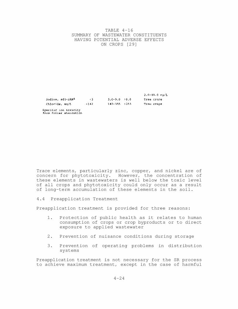
4-24
TABLE 4-16SUMMARY OF WASTEWATER CONSTITUENTSHAVING POTENTIAL ADVERSE EFFECTS
ON CROPS [29]
Trace elements, particularly zinc, copper, and nickel are ofconcern for phytotoxicity. However, the concentration ofthese elements in wastewaters is well below the toxic levelof all crops and phytotoxicity could only occur as a resultof long-term accumulation of these elements in the soil.
4.4 Preapplication Treatment
Preapplication treatment is provided for three reasons:
1. Protection of public health as it relates to humanconsumption of crops or crop byproducts or to directexposure to applied wastewater
2. Prevention of nuisance conditions during storage
3. Prevention of operating problems in distributionsystems
Preapplication treatment is not necessary for the SR processto achieve maximum treatment, except in the case of harmful

4-25
or toxic constituents from industrial sources (see Section4.4.3). The SR process is capable of removing high levels ofmost constituents present in municipal wastewaters, andmaximum use should be made of this renovative capacity in acomplete treatment system. Therefore, the level ofpreapplication treatment provided should be the minimumnecessary to achieve the three stated objectives. Ingeneral, any additional preapplication treatment will resultin higher costs and energy use.
The EPA has issued general guidelines for assessing thelevel of preapplication treatment necessary for SR systems[30]. The guidelines are intended to provide adequateprotection for public health:
A. Primary treatment - acceptable for isolatedlocations with restricted public access and whenlimited to crops not for direct human consumption.
B. Biological treatment by ponds or inplant processesplus control of fecal coliform count to less than1,000 MPN/100 mL - acceptable for controlledagricultural irrigation except for human food cropsto be eaten raw.
C. Biological treatment by ponds or inplant processeswith additional BOD or SS control as needed foraesthetics plus disinfection to log mean of 200/100mL (EPA fecal coliform criteria for bathing waters)- acceptable for application in public access areassuch as parks and golf courses.
In most cases, state or local public health or water qualitycontrol agencies regulate the quality of municipal wastewaterthat can be used for SR. The appropriate state and localagencies should be contacted early in the design process todetermine specific restrictions on the quality of appliedwastewater.
4.4.1 Preapplication Treatment for Storage andDuring Storage
Objectionable odors and nuisance conditions can occur ifanaerobic conditions develop near the surface in a storagepond. Two preapplication treatment options are available toprevent odors:
1. Reduce the oxygen demand of the wastewater prior tostorage.

4-26
2. Design the storage pond as a deep facultative pond,using appropriate BOD loading.
Complete biological treatment and disinfection areunnecessary prior to storage. The level of treatmentprovided should not exceed that necessary to control odors.For storage ponds with short detention times (less than 10 to15 days), a reduction in the BOD of the wastewater to a rangeof 40 to 75 mg/L should be sufficient to prevent odors. Anaerated cell is are normally used for BOD reduction in suchcases. For storage ponds with longer detention times, BODreduction before storage is normally not required because thestorage pond is serving as a stabilization pond.
Wastewater undergoes treatment during storage. Suspendedsolids, oxygen demand, nitrogen, and microorganisms arereduced. In general, the extent of reduction depends on thelength of the storage period. In the case of nitrogen,removal during storage can affect the design and operation ofthe SR process because the allowable hydraulic loading ratemay be governed by the nitrogen concentration of the appliedwastewater. Nitrogen removal in storage reservoirs can besubstantial and depends on several factors includingdetention time, temperature, pH, and pond depth. Apreliminary model to estimate nitrogen removals in pondsduring ice—free periods has been developed [31]:
N = N e (4-1)t 0 —0.0075t
where N = nitrogen concentration in pond effluentt
(total N), mg/L
N = nitrogen concentration entering pondo
(total N), mg/L
t = detention time, d
A more precise model for predicting ammonia nitrogen removalsin ponds is presented in the Process Design Manual onWastewater Treatment ponds [32].
Nitrogen in pond effluent is predominantly in the ammonia ororganic form. In most cases, it is desirable to applynitrogen in these forms to SR systems because they are heldat least temporarily in the soil profile and are availablefor plant uptake for longer periods than nitrate, which ismobile in the soil profile. Ammonia and organic nitrogenwhich is converted to ammonia, are particularly desirable in
4-27
forest systems because many tree species do not take upnitrate as efficiently as ammonia.
A model describing the removal of fecal coliforms in pondsystems has also been developed [33]:
C = C e (4—2)f i-Kt2(T-20)
where C = effluent fecal coliform concentration,f
No./100 mL
C = entering fecal coliform concentration,i
No./100 mL
K = 0.5 warm months; 0.03 cold months
t = “actual” detention time, d
2 = 1.072
T = liquid temperature, EC
Based on this model, actual detention times of about 17 daysand 21 days would be necessary at 20 EC (68 EF) to reduce thecoliform level of a typical domestic wastewater to 1,000/100mL and 200/100 mL, respectively. Thus, effluent from storagereservoirs, in many cases, may meet the EPA coliformrecommendations for SR systems without disinfection.
Removal of viruses in ponds is also quite rapid at warmtemperatures. Essentially complete removal of Coxsackie andpolio viruses was observed after 20 days at 20 C [34]E
4.4.2 Preapplication Treatment to ProtectDistribution Systems
Deposition of settleable solids and grease in distributionlaterals or ditches can cause reduction in the flow capacityof the distribution network and odors at the point ofapplication. Coarse solids can cause severe cloggingproblems in sprinkler distribution systems. Removal ofsettleable solids and oil and grease (i.e., primarysedimentation or equivalent) is therefore recommended as aminimum level of preapplication treatment. For sprinklersystems, it has been recommended that the size of the largestparticle in the applied wastewater be less than one-third thediameter of the sprinkler nozzle to avoid plugging.

4-28
4.4.3 Industrial pretreatment
Pollutants that are compatible with conventional secondarytreatment systems would generally be compatible with landtreatment systems. As with conventional systems, pre-treatment requirements will be necessary for such constit-uents as fats, grease and oils, and sulfides to protectcollection systems and treatment components. Pretreatmentrequirements for conventional biological treatment will alsobe sufficient for land treatment processes.
4.5 Loading Rates and Land Area Requirements
The hydraulic loading rate is the volume of wastewaterapplied per unit area of land over at least one loadingcycle. Hydraulic loading rate is commonly expressed in cm/wkor in/yr (in./wk or ft/yr) and is used to compute the landarea required for the SR process. The hydraulic loading rateused for design is based on the more restrictive of twolimiting conditions——the capacity of the soil profile totransmit water (soil permeability) or the nitrogenconcentration in water percolating beyond the root zone.
A separate case is considered for those systems in aridregions where crop revenue is important and the wastewater isused as a valuable source of irrigation water. For suchsystems, the design hydraulic loading rate is usually basedon the irrigation requirements of the crop.
4.5.1 Hydraulic Loading Rate Based on Soilpermeability
The general water balance equation with rates based on amonthly time period is the basis of this procedure. Theequation, with runoff of applied water assumed to be zero,is:
L = ET - Pr + P (4-3)w w
where L = wastewater hydraulic loading ratew
ET = evapotranspiration rate
Pr = precipitation rate
P = percolation ratew
4-29
The basic steps in the procedure are:
1. Determine the design precipitation for each monthbased on a 5 year return period frequency analysisfor monthly precipitation. Alternatively, use a 10year return period for annual precipitation anddistribute it monthly based on the ratio of averagemonthly to average annual precipitation.
2. Estimate the monthly ET rate of the selected crop(see Section 4.3.2.3).
3. Determine by field test the minimum clear waterpermeability of the soil profile. If the minimumsoil permeability is variable over the site,determine an average minimum permeability based onareas of different soil types.
4. Establish a maximum daily design percolation ratethat does not exceed 4 to 10% of minimum soilpermeability (see Figure 2—3). Percentages on thelower end of the scale are recommended for variableor poorly defined soil conditions. The percentageto use is a judgment decision to be made by thedesigner. The daily percolation rate is determinedas follows:
P = permeability, cm/h (24 h/d)(4 to 10%)w(daily)
5. Calculate the monthly percolation rate withadjustments for those months having periods ofnonoperation. Nonoperation may be due to:
! Crop management. Downtime must be allowed for harvesting,planting, and cultivation as applicable.
! Precipitation. Downtime for precipitation is alreadyfactored into the water balance computation. No adjust-ments are necessary.
! Freezing temperatures. Subfreezing temperatures cause soilfrost that reduces surface infiltration rate. Operation isusually stopped when this occurs. The most conservativeapproach to adjusting the monthly percolation rate forfreezing conditions is to allow no operation for daysduring the month when the mean temperature is less than 0EC (32 F). A less conservative approach is to use a lowerE
minimum temperature. The recommended lowest meantemperature for operation is -4 C (25 F). Data sourcesE E
and procedures for determining the number of subfreezingdays during a month are presented in Sections 2.2.1.3,
4-30
2.2.2.2, and 4.6. Nonoperating days due to freezing con-ditions may also be estimated using the EPA-l computerprogram without precipitation constraints (see Section4.6.2). For forest crops, operation can often continueduring subfreezing conditions.
! Seasonal crops. When single annual crops are grown,wastewater is not normally applied during the winterseason, although applications may occur after harvest andbefore the next planting. The design monthly percolationrate may be calculated as follows:
P = [P ] x (No. of operating d/mo)w(monthly) w(daily)
6. Calculate the monthly hydraulic loading rate usingEquation 4—3. The monthly hydraulic loadings aresummed to yield the allowable annual hydraulicloading rate based on soil permeability [L ]. TheW(P)
computation procedure is illustrated by an examplefor both arid and humid climates in Table 4—17. Theexample is based on systems growing permanentpasture and having similar winter weather and soilconditions. Downtime is allowed for freezingconditions, but pasture management does not requireharvesting downtime.
The allowable hydraulic loading rate based on soilpermeability calculated by the above procedure L is thew(P)
maximum rate for a particular site and operating conditions,and this rate will be used for design if there are no otherconstraints or limitations. If other limitations exist, suchas percolate nitrogen concentration, it is necessary tocalculate the allowable hydraulic loading rate based on theselimitations and compare that rate with the L . The lowerw(P)
of the two rates is used for design.
4.5.2 Hydraulic Loading Rate Based onNitrogen Limits
In municipal wastewaters applied to SR systems, nitrogen isusually the limiting constituent when protection of potableground water aquifers is a concern. If percolating water from an SR system will enter a potable ground water aquifer,then the system should be designed such that theconcentration of nitrate nitrogen in the receiving groundwater at the project boundary does not exceed 10 mg/L.

4-31
TABLE 4—17WATER BALANCE TO DETERMINE HYDRAULIC LOADING
RATES BASED ON SOIL PERMEABILITYcm
The approach to meeting this requirement involves firstestimating an allowable hydraulic loading rate based on anannual nitrogen balance (L ), and comparing that to thew(n)
previously calculated L to determine which value controls.w(p)
The detailed steps in this procedure are:
1. Calculate the allowable annual hydraulic loadingrate based on nitrogen limits using the followingequation:
4-32
where L = allowable annual hydraulic loading rateW(n)
based on nitrogen limits, cm/yr
C = nitrogen concentration in percolatingp
water, mg/L
Pr = precipitation rate, cm/yr
ET = evapotranspiration rate, cm/yr
U = nitrogen uptake by crop, kg/ha•yr(Tables 4-2, 4-11, 4-12)
C = nitrogen concentration in appliedn
wastewater, mg/L (after losses inpreapplication treatment)
f = fraction of applied nitrogen removed bydenitrification and volatilization(4.2.2).
2. Compare the value of L with the value of Lw(n) w(p)
calculated previously (Section 4.5.1). If L isw(n)
greater than L , do not continue the procedure andw(p)
use L for design. If L is less than or equalw(p) w(n)
to L , design should be based on L . The valuew(p) w(n)
of L calculated in Step 1 above may be used tow(n)
estimate land requirements for purposes of Phase 2planning, but for final design the procedureoutlined in Steps 3 and 4 should be used.
3. Calculate an allowable monthly hydraulic loadingrate based on nitrogen limits using Equation 4—4with monthly values for Pr, ET, and U. Monthlyvalues for Pr and ET will have been determinedpreviously for the water balance table (see Section4.5.1). Monthly values for crop uptake (U) can beestimated by assuming that annual crop uptake isdistributed monthly according to the same ratio asmonthly to total growing season ET.
If data on nitrogen uptake versus time, such as thatshown in Figure 4—2, are available for the crops andclimatic region specific to the project underdesign, then such information may be used to developa more accurate estimate of monthly nitrogen uptakevalues.
4. Compare each monthly value of L with thew(n)
corresponding monthly value of L calculatedw(p)
4-33
previously (Section 4.5.1). The lower of the twovalues should be used for design. The designmonthly hydraulic loading rates are summed to yieldthe design annual hydraulic loading rate.
The above procedure is illustrated in Example 4—1for an arid climate and a humid climate using theclimatic and operating conditions given in Table4—17.
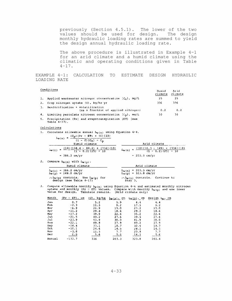
EXAMPLE 4-1: CALCULATION TO ESTIMATE DESIGN HYDRAULICLOADING RATE

4-34
The above procedure for calculating allowable hydraulicloading rate based on nitrogen limits is based on thefollowing assumptions:
1. All percolate nitrogen is in the nitrate form.
2. No storage of nitrogen occurs in the soil profile.
3. No mixing and dilution of the percolate with in situground water occurs.
Use of these assumptions results in a very conservativeestimate of percolate nitrogen. This procedure should ensurethat the nitrogen concentration in the ground water at theproject boundaries will be less than the specified value ofC .p
As indicated by the example, nitrogen loading is more likelyto govern the design hydraulic loading rate for systems inarid climates than in humid climates. The reason for this isthat the net positive ET rate in arid climates causes anincrease in the concentration of the nitrogen level in thepercolating water.
For systems in arid climates, it is possible that the designmonthly hydraulic loading rates based on nitrogen limits willbe less than the irrigation requirements (IR) of the crop.The designer should compare the design L with the irrigationw
requirement to determine if this situation exists. If itdoes exist, the designer has three options available toincrease L sufficiently to meet the IR.w(n)
1. Reduce the concentration of applied nitrogen (C )nthrough preapplication treatment.
2. Demonstrate that sufficient mixing and dilution (seeSection 3.6.2) will occur with the existing groundwater to permit higher values of percolate nitrogenconcentration (C ) to be used in Equation 4-4.p
3. Select a different crop with a higher nitrogenuptake (U).
4.5.3 Hydraulic Loading Rate Based onIrrigation Requirements
For SR systems in arid regions that have crop production forrevenue as the objective, the design hydraulic loading ratecan be determined on the basis of the crop irrigation
4-35
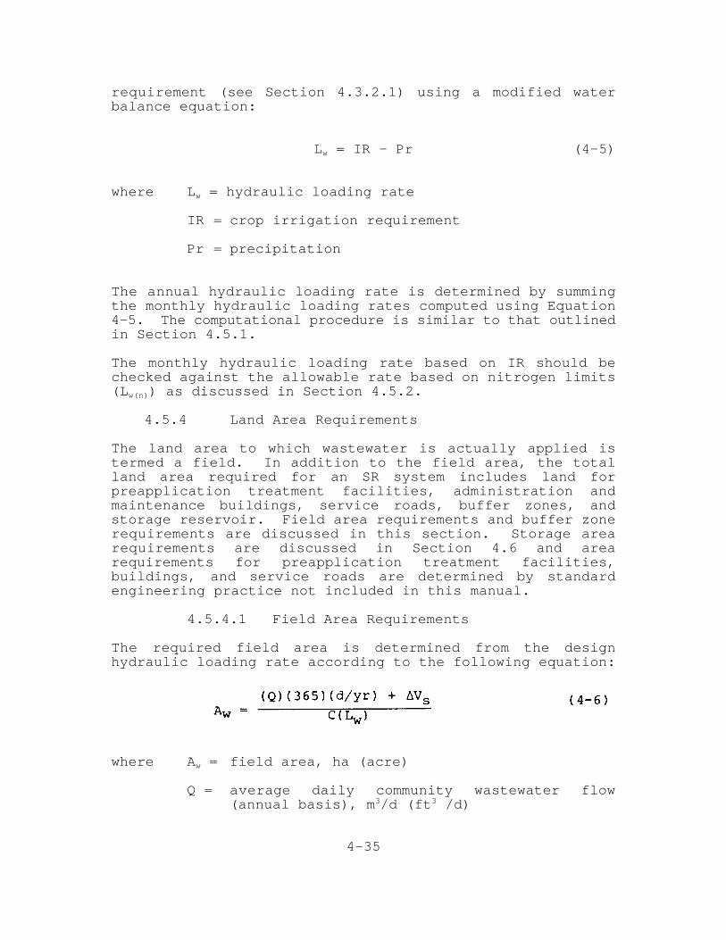
requirement (see Section 4.3.2.1) using a modified waterbalance equation:
L = IR — Pr (4-5)w
where L = hydraulic loading ratew
IR = crop irrigation requirement
Pr = precipitation
The annual hydraulic loading rate is determined by summingthe monthly hydraulic loading rates computed using Equation4-5. The computational procedure is similar to that outlinedin Section 4.5.1.
The monthly hydraulic loading rate based on IR should bechecked against the allowable rate based on nitrogen limits(L ) as discussed in Section 4.5.2.w(n)
4.5.4 Land Area Requirements
The land area to which wastewater is actually applied istermed a field. In addition to the field area, the totalland area required for an SR system includes land forpreapplication treatment facilities, administration andmaintenance buildings, service roads, buffer zones, andstorage reservoir. Field area requirements and buffer zonerequirements are discussed in this section. Storage arearequirements are discussed in Section 4.6 and arearequirements for preapplication treatment facilities,buildings, and service roads are determined by standardengineering practice not included in this manual.
4.5.4.1 Field Area Requirements
The required field area is determined from the designhydraulic loading rate according to the following equation:
where A = field area, ha (acre)w
Q = average daily community wastewater flow(annual basis), m /d (ft /d)3 3
4-36
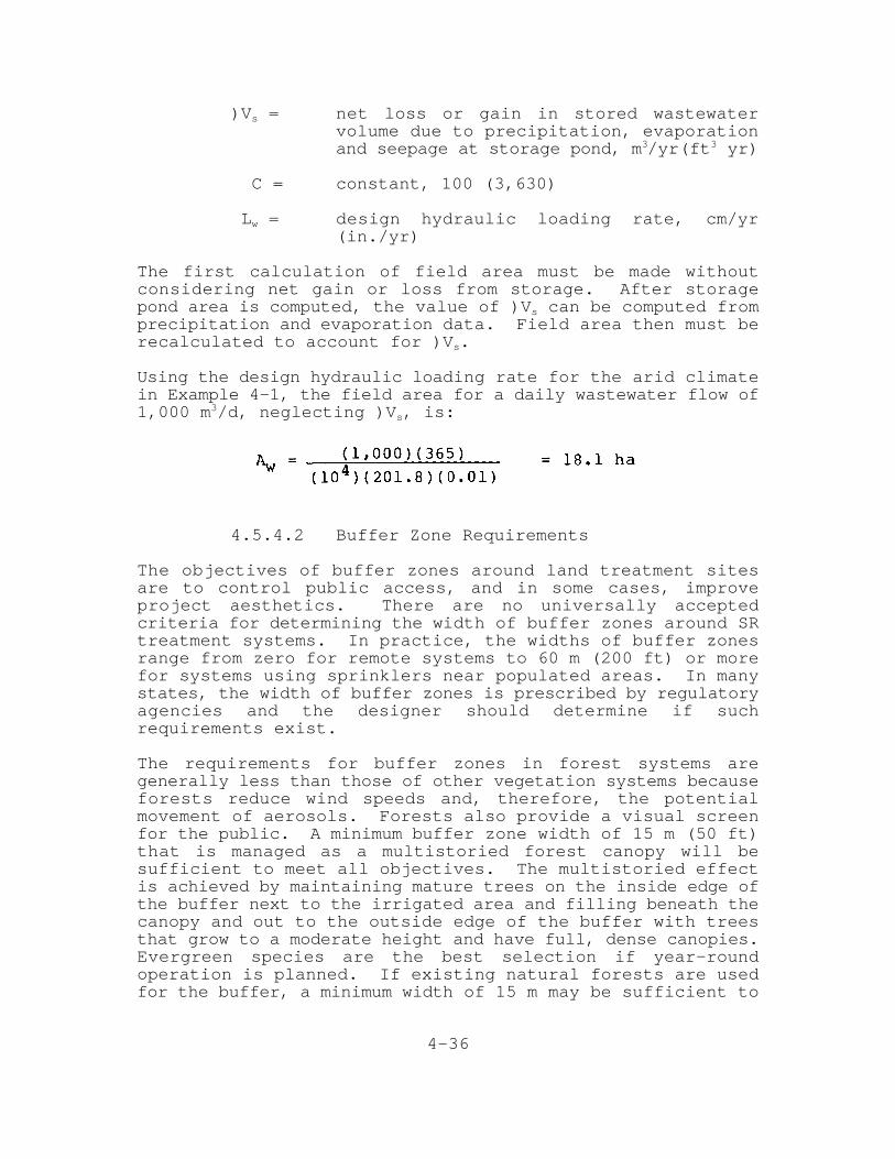
)V = net loss or gain in stored wastewaters
volume due to precipitation, evaporationand seepage at storage pond, m /yr(ft yr)3 3
C = constant, 100 (3,630)
L = design hydraulic loading rate, cm/yrw
(in./yr)
The first calculation of field area must be made withoutconsidering net gain or loss from storage. After storagepond area is computed, the value of )V can be computed froms
precipitation and evaporation data. Field area then must berecalculated to account for )V .s
Using the design hydraulic loading rate for the arid climatein Example 4-1, the field area for a daily wastewater flow of1,000 m /d, neglecting )V , is:3
s
4.5.4.2 Buffer Zone Requirements
The objectives of buffer zones around land treatment sitesare to control public access, and in some cases, improveproject aesthetics. There are no universally acceptedcriteria for determining the width of buffer zones around SRtreatment systems. In practice, the widths of buffer zonesrange from zero for remote systems to 60 m (200 ft) or morefor systems using sprinklers near populated areas. In manystates, the width of buffer zones is prescribed by regulatoryagencies and the designer should determine if suchrequirements exist.
The requirements for buffer zones in forest systems aregenerally less than those of other vegetation systems becauseforests reduce wind speeds and, therefore, the potentialmovement of aerosols. Forests also provide a visual screenfor the public. A minimum buffer zone width of 15 m (50 ft)that is managed as a multistoried forest canopy will besufficient to meet all objectives. The multistoried effectis achieved by maintaining mature trees on the inside edge ofthe buffer next to the irrigated area and filling beneath thecanopy and out to the outside edge of the buffer with treesthat grow to a moderate height and have full, dense canopies.Evergreen species are the best selection if year-roundoperation is planned. If existing natural forests are usedfor the buffer, a minimum width of 15 m may be sufficient to

4-37
meet the objectives, if there is an adequate vegetationdensity.
4.6 Storage Requirements
In almost all cases, SR systems require some storage forperiods when the amount of available wastewater flow exceedsthe design hydraulic loading rate. The approach used todetermine storage requirements is to first estimate a storagevolume requirement using a water balance computation orcomputer programs developed to estimate storage needs basedon observed climatic variations throughout the United States.The final design volume then is determined by adjusting theestimated volume for net gain or loss due to precipitationand evaporation using a monthly water balance on the storagepond. These estimating and adjustment procedures aredescribed in the following sections.
Some states prescribe a minimum storage volume (e.g., 10 daysstorage). The designer should determine if such storagerequirements exist.
All applied wastewater does not need to pass through thestorage reservoir. In cases where primary effluent issuitable for application, only the water that must be storedneed receive prestorage treatment. Stored and freshwastewater is then blended for application.
4.6.1 Estimation of Volume Requirements UsingStorage Water Balance Calculations
An initial estimate of the storage volume requirements may bedetermined using a water balance calculation procedure. Thebasic steps in the procedure are illustrated using the aridclimate example from Example 4—1:
1. Tabulate the design monthly hydraulic loading rateas indicated in Table 4—17.
2. Convert the actual volume of wastewater availableeach month to units of depth (cm) using thefollowing relationship.
where W = depth of available wastewater, cma
Q = volume of available wastewater for them
month, m3

4-38
A = field area, haw
Insert the results for each month into a waterbalance table, as illustrated by the example inTable 4-18. In some communities, influentwastewater flow varies significantly with the timeof year. The values used for Q should reflectm
monthly flow variation based on historical records.In this example, no monthly flow variation isassumed.
TABLE 4—18ESTIMATION OF STORAGE VOLUME REQUIREMENTS
USING WATER BALANCE CALCULATIONScm
3. Compute the net change in storage each month bysubtracting the monthly hydraulic loading from theavailable wastewater in the same month.
4. Compute the cumulative storage at the end of eachmonth by adding the change in storage during onemonth to the accumulated quantity from the previousmonth. The computation should begin with thereservoir empty at the beginning of the largeststorage period. This month is usually October orNovember, but in some humid areas it may be Februaryor March.
4-39
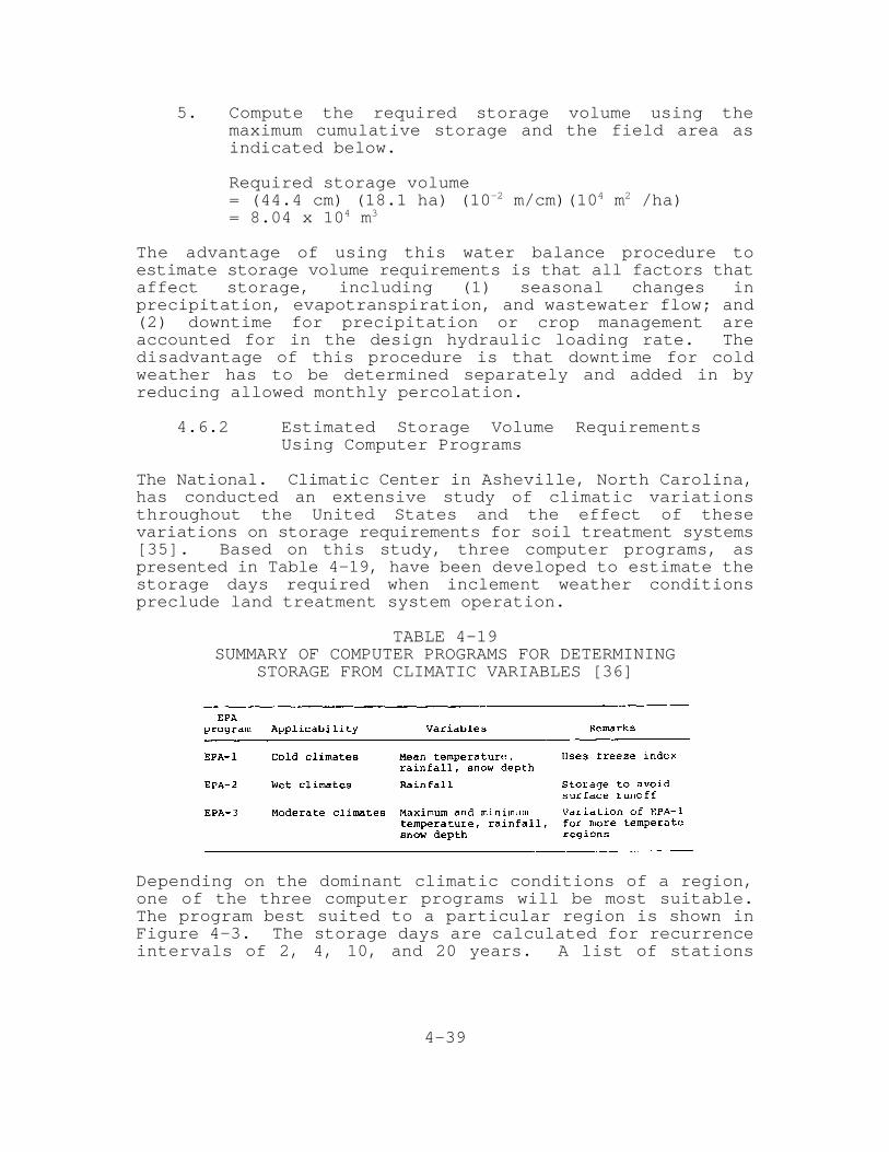
5. Compute the required storage volume using themaximum cumulative storage and the field area asindicated below.
Required storage volume= (44.4 cm) (18.1 ha) (10 m/cm)(10 m /ha)-2 4 2
= 8.04 x 10 m4 3
The advantage of using this water balance procedure toestimate storage volume requirements is that all factors thataffect storage, including (1) seasonal changes inprecipitation, evapotranspiration, and wastewater flow; and(2) downtime for precipitation or crop management areaccounted for in the design hydraulic loading rate. Thedisadvantage of this procedure is that downtime for coldweather has to be determined separately and added in byreducing allowed monthly percolation.
4.6.2 Estimated Storage Volume RequirementsUsing Computer Programs
The National. Climatic Center in Asheville, North Carolina,has conducted an extensive study of climatic variationsthroughout the United States and the effect of thesevariations on storage requirements for soil treatment systems[35]. Based on this study, three computer programs, aspresented in Table 4—19, have been developed to estimate thestorage days required when inclement weather conditionspreclude land treatment system operation.
TABLE 4-19SUMMARY OF COMPUTER PROGRAMS FOR DETERMINING
STORAGE FROM CLIMATIC VARIABLES [36]
Depending on the dominant climatic conditions of a region,one of the three computer programs will be most suitable.The program best suited to a particular region is shown inFigure 4-3. The storage days are calculated for recurrenceintervals of 2, 4, 10, and 20 years. A list of stations
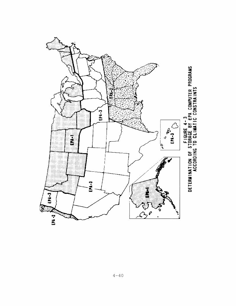
4-40
4-41
with storage days for 10 and 20 year recurrence intervalsfrom EPA computer programs is presented in Appendix F. Alist of 244 stations for which EPA-l has been run is includedin reference [35]. To use these programs, contact theNational Climatic Center of the National Oceanic andAtmospheric Administration in Asheville, North Carolina28801; a fee is required.
Storage days required for crop management activities(harvesting, planting, etc.) must be added to the computerestimated storage days due to weather to obtain the totalstorage days required in each month. The estimated requiredstorage volume is then calculated by multiplying theestimated number of storage days in each month times theaverage daily flow for the corresponding month.
4.6.3 Final Design Storage Volume Calculations
The estimated storage volume requirement obtained by waterbalance calculation or computer programs must be adjusted toaccount for net gain or loss in volume due to precipitationor evaporation. The mass balance procedure is Illustrated byExample 4-2 using arid climate data from Example 4-1 and theestimated storage volume from Table 4-18. An example for asystem in a more humid climate is given in Appendix E.
EXAMPLE 4-2: CALCULATIONS TO DETERMINE FINAL STORAGE VOLUMEREQUIREMENTS

4-42

4-43
4.6.4 Storage Pond Design Considerations
Most agricultural storage ponds are constructed ofhomogeneous earth embankments, the design of which conformsto the principles of small dam design. Depending on themagnitude of the project, state regulations may govern thedesign. In California, for example, any reservoir withembankments higher than 1.8 m (6 ft) and a capacity in excessof 61,800 m (50 acre-ft) is subject to state regulations on3
design and construction of dams, and plans must be reviewedand approved by the appropriate agency. Design criteria andinformation sources are included in the U.S. Bureau ofReclamation publication, Design of Small Dams [37]. In manycases, it will be necessary that a competent soils engineerbe consulted for proper soils analyses and structural designof foundations and embankments.
In addition to storage volume, the principal designparameters are depth and area. The design depth and areadepend on the function of the pond and the topography at thepond site. If the storage pond is to also serve as afacultative pond, then a minimum water depth of at least 0.5to 1 m (1.5 to 3 ft) should be maintained in the pond whenthe stored volume is at a minimum. The area must also besufficient to meet the BOD pond loading criteria for thelocal climate. The use of aerators can reduce arearequirements. The maximum depth depends on whether thereservoir is constructed with dikes or embankments on levelground or is constructed by damming a natural water course orravine. Maximum depths of diked ponds typically range from3 to 6 m (9 to 18 ft). Other design considerations includewind fetch, and the need for riprap and lining. Theseaspects of design are covered in standard engineeringreferences and assistance is also available from local SCSoffices.
4-44
4.7 Distribution System
Design of the distribution system involves two steps: (1)selection of the type of distribution system, and (2)detailed design of system components. Emphasis in thissection is placed on criteria for selection of the type ofdistribution system. Design procedures for SR distributionsystems are presented in Appendix E. Only basic designprinciples for each type of distribution system are presentedin the manual, and the designer is referred to severalstandard agricultural engineering references for furtherdesign details. Certain design requirements of distributionsystems for forest crop systems do not conform to standardagricultural irrigation practice and are discussed under aseparate heading.
4.7.1 Surface Distribution Systems
With surface distribution systems, water is applied to theground surface at one end of a field and allowed to spreadover the field by gravity. Conditions favoring the selectionof a surface distribution system include the following:
1. Capital is not available for the initial investmentrequired for more sophisticated systems.
2. Skilled labor is available at reasonable rates tooperate a surface system.
3. Surface topography of land requires littleadditional preparation to make uniform grades forsurface distribution.
The principal limitations or disadvantages of surface systemsinclude the following:
1. Land leveling costs may be excessive on uneventerrain.
2. Uniform distribution cannot be achieved with highlypermeable soils.
3. Runoff control and a return system must be providedwhen applying wastewater.
4. Skilled labor is usually required to achieve properperformance.
5. Periodic maintenance of leveled surface is requiredto maintain uniform grades.
4-45
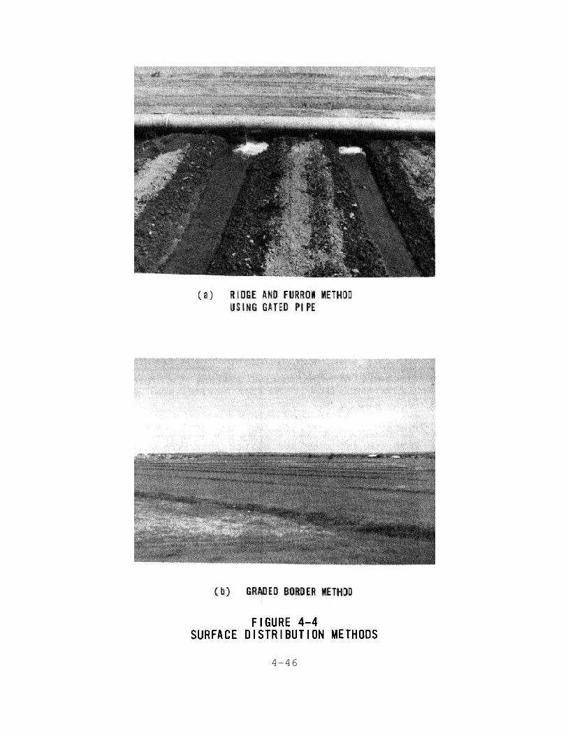
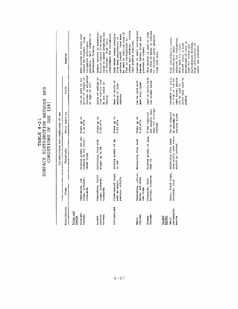
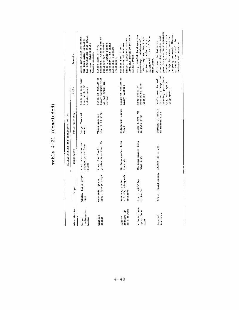
Surface distribution systems may be classified into twogeneral types: ridge and furrow and graded border (alsotermed bermed cell). The distinguishing physical features ofthese methods are illustrated in Figure 4-4. A summary ofvariations of the basic surface methods and conditions fortheir use is presented in Table 4-21. Details of preliminarydesign are presented in Appendix E.
4.7.2 Sprinkler Distribution Systems
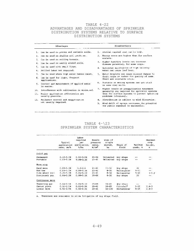
Sprinkler distribution systems simulate rainfall by creatinga rotating jet of water that breaks up into small dropletsthat fall to the field surface. The advantages anddisadvantages of sprinkler distribution systems relative tosurface distribution systems are summarized in Table 4-22.
4.7.2.1 Types of Sprinkler Systems
In this manual, sprinkler systems are classified according totheir movement during and between applications because thischaracteristic determines the procedure for design. Thereare three major categories of sprinkler systems based onmovement:(1) solid set, (2) move-stop, and (3) continuousmove. A summary of the various types of sprinkler systemsunder each category is given in Table 4-23 along withrespective operating characteristics.
4.7.2.2 Sprinkler Distribution Systems for Forest
The requirements of distribution systems for forests aresomewhat different from those for agricultural and turfcrops. Solid—set irrigation systems are the most commonlyused systems in forests. Buried systems are less susceptibleto damage from ice and snow and do not interfere with forestmanagement activities (thinning, harvesting, andregeneration). A center pivot irrigation system has beenused in Michigan for irrigation of Christmas trees becausetheir growth height would not exceed the height of the pivotarms. Traveling guns have also been used to irrigate short-term rotation hardwood plantations.
As discussed in Section 4.3.2.4, the design sprinklerapplication rate is usually not limited by the infiltrationcapacity of most forest soils. Steep grades (up to 35%), ingeneral, do not limit the design hydraulic loading rate perapplication for forest systems. In fact, hydraulic loadingsper application may be increased up to 10% on grades greaterthan 15% because of the higher drainage rate. Precautionsmust be taken to make sure that water draining through thesurface soil does not appear as runoff further down theslope.
4-46
4-47
4-48
4-49
TABLE 4-22ADVANTAGES AND DISADVANTAGES OF SPRINKLERDISTRIBUTION SYSTEMS RELATIVE TO SURFACE
DISTRIBUTION SYSTEMS
TABLE 4-\23SPRINKLER SYSTEM CHARACTERISTICS
4-50
Solid set sprinkler systems for forest crops have somespecial design requirements. Spacing of sprinkler heads mustbe closer and operating pressures lower in forests than othervegetation systems because of the interference from treetrunks and leaves and possible damage to bark. An 18 m (60ft) spacing between sprinklers and a 24 m (80 ft) spacingbetween laterals has proven to be an acceptable spacing forforested areas [39]. This spacing, with sprinkler overlap,provides good wastewater distribution at a reasonable cost.Operating pressures at the nozzle should not exceed 38 N/cm2
(55 lb/in ), although pressures up to 59 N/cm (85 lb/in )2 2 2
may be used with mature or thickbarked hardwood species. Thesprinkler risers should be high enough to raise the sprinklerabove most of the understory vegetation, but generally notexceeding 1.5 m (5 ft). Low-trajectory sprinklers should beused so that water is not thrown into the tree canopies,particularly in the winter when ice buildup on pines andother evergreen trees can cause the trees to be broken oruprooted.
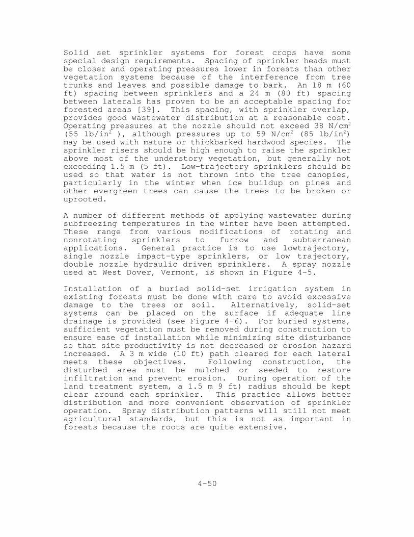
A number of different methods of applying wastewater duringsubfreezing temperatures in the winter have been attempted.These range from various modifications of rotating andnonrotating sprinklers to furrow and subterraneanapplications. General practice is to use lowtrajectory,single nozzle impact-type sprinklers, or low trajectory,double nozzle hydraulic driven sprinklers. A spray nozzleused at West Dover, Vermont, is shown in Figure 4-5.
Installation of a buried solid-set irrigation system inexisting forests must be done with care to avoid excessivedamage to the trees or soil. Alternatively, solid-setsystems can be placed on the surface if adequate linedrainage is provided (see Figure 4-6). For buried systems,sufficient vegetation must be removed during construction toensure ease of installation while minimizing site disturbanceso that site productivity is not decreased or erosion hazardincreased. A 3 m wide (10 ft) path cleared for each lateralmeets these objectives. Following construction, thedisturbed area must be mulched or seeded to restoreinfiltration and prevent erosion. During operation of theland treatment system, a 1.5 m 9 ft) radius should be keptclear around each sprinkler. This practice allows betterdistribution and more convenient observation of sprinkleroperation. Spray distribution patterns will still not meetagricultural standards, but this is not as important inforests because the roots are quite extensive.
4-51

4-52
4-53
4.7.3 Service Life of Distribution SystemComponents
The expected service life of the distribution systemcomponents is a design consideration and must be used todevelop detailed cost comparison. The suggested servicelives of common distribution system components are listed inTable 4-24.
4.8 Drainage and Runoff Control
Provisions to improve or control subsurface drainage aresometimes necessary with SR systems to remove excess waterfrom the root zone or to remove salts from the root zone whenthese conditions adversely affect crop growth. Control ofsurface runoff is necessary for SR systems using surfacedistribution methods. In humid areas with intense rain—falls, control of surface drainage is necessary to preventerosion and may be helpful in reducing the amount of waterentering the soil profile and thereby reducing or eliminatingthe need for subsurface drainage. Design considerations fordrainage and runoff control provisions are discussed in thefollowing sections.
4.8.1 Subsurface Drainage Systems
Subsurface drainage systems are used in situations where thenatural rate of subsurface drainage is restricted byrelatively impermeable layers in the soil profile near thesurface or by high ground water. As a result of therestrictive layer, shallow ground water tables can form thatextend into the root zone and even to the soil surface.
The major consideration for wastewater treatment is themaintenance of an aerobic zone in the upper soil profile.Many of the wastewater removal mechanisms require an aerobicenvironment to function most effectively. A travel distanceof 0.6 to 1 m (2 to 3 ft) through aerobic soil is consideredthe minimum distance to achieve treatment by the SR process.Therefore, a water table depth of 1 m (3 ft) or more isdesirable from a wastewater treatment standpoint.

4-54
TABLE 4-24SUGGESTED SERVICE LIFE FOR COMPONENTS OF
DISTRIBUTION SYSTEM [40]

4-55
For SR systems where wastewater treatment and maximumhydraulic loading rate are the design objectives, thepresence of excess moisture in the root zone is of limitedconcern for crops because water tolerant crops are generallyselected for such systems. However, restrictive subsurfacelayers and resulting high water tables limit the allowablepercolation rate and, therefore, the design hydraulic loadingrate. Subsurface drains placed above the restrictive layereliminate the effect of that layer on percolation and allowthe design percolation rate to be based on more permeableoverlying soil horizons. The design hydraulic loading rateis thereby increased.
In arid regions, the additional problem of salinity controlis encountered. With such systems, excess water is appliedto remove salts that concentrate in the root zone (Section4.3.2.3). Where the natural drainage rate is insufficient toremove salty leaching water from the root zone within 2 to 3days, crop damage due to salinity may occur depending on thetolerance of the crop and the salinity of the applied water(see Section 4.3.2.5). In such cases, the objectives of asubsurface drainage system are to (1) prevent the persistenceof high water tables when leaching is practiced, and (2) tokeep the water table sufficiently low between growing seasonsto minimize evaporation from the water table and resultingsalt accumulation in the root zone. As a rule of thumb, thewater table should not be permitted to come closer than about125 cm (49 in.) from the surface to prevent saltaccumulation. This minimum depth is greater than thosegenerally used in humid areas. Any drainage water from croprevenue systems that is discharged to surface waters mustmeet applicable discharge requirements.
The decision to use subsurface drains must be based on theeconomic benefit to be gained from their use. For example,the cost of installing and maintaining a subsurface drainsystem should be compared to the value of developing anotherwise unsuitable site or to the cost of a larger landarea that will be required if subsurface drains are not used.
Buried plastic, concrete, and clay tile lines are normallyused for underdrains. The choice usually depends on priceand availability of materials. Where sulfates are present inthe ground water, it is necessary to use a sulfate-resistantcement, if concrete pipe is chosen, to prevent excessinternal stress from crystal formation. Most tile drains aremechanically laid in a machine dug trench or by directplowing. Open trenches can be used for subsurface drainage,but if closely spaced, they can interfere with farmingoperations and consume usable land.

4-56
Underdrains are normally buried 1.8 to 2.4 m (6 to 8 ft) deepbut can be as deep as 3 m (10 ft) or as shallow as 1 m (3ft). Drains are normally 10 to 15 cm (4 to 6 in.) indiameter. Spacings as small as 15 to 30 m (50 to 100 ft) maybe required for clayey soils. For sandy soils, 120 m (400ft) is typical with the range being from 60 to 300 m (200 to1,000 ft).
Procedures for determining the proper depth and spacing ofdrain lines to maintain the water table below a minimum depthare discussed in Section 5.7. Additional detailed designprocedures and engineering aspects of subsurface drainagesystems are described in references [41, 42, 43].
4.8.2 Surface Drainage and Runoff Control
Drainage and control of surface runoff is a designconsideration for SR systems as it relates to tailwater fromsurface distribution systems and stormwater runoff from allsystems.
4.8.2.1 Tailwater Return Systems
Most surface distribution systems will produce some runoff,which is referred to as tailwater. When partially treatedwastewater is applied, tailwater must be contained within thetreatment site and reapplied. Thus a tailwater return systemis an integral part of an SR system using surfacedistribution methods. A typical tailwater return systemconsists of a sump or reservoir, a pump(s), and returnpipeline.
The simplest and most flexible type of system is a storagereservoir system in which all or a portion of the tailwaterflow from a given application is stored and eithertransferred to a main reservoir for later reapplication orreapplied from the tailwater reservoir to other portions ofthe field. Tailwater return systems should be designed todistribute collected water to all parts of the field, notconsistently to the same area. If all the tailwater isstored, pumping can be continuous and can commence at theconvenience of the operator. Pumps can be any convenientsize, but a minimum capacity of 25% of the distributionsystem capacity is recommended [44]. If a portion of thetailwater flow is stored, the reservoir capacity can bereduced but pumping must begin during tailwater collection.
Cycling pump systems and continuous pumping systems can bedesigned to minimize the storage volume requirements, butthese systems are much less flexible than storage systems.The designer is directed to reference [44] for designprocedures.
4-57
The principal design variables for tailwater return systemsare the volume of tailwater and the duration of tailwaterflow. The expected values of these parameters for a well-operated system depend on the infiltration rate of the soil.Guidelines for estimating tailwater volume, the duration oftailwater flow, and suggested maximum design tailwater volumeare presented in Table 4-25.
TABLE 4-25RECOMMENDED DESIGN FACTORS
FOR TAILWATER RETURN SYSTEMS [44]
Runoff of applied wastewater from sites with sprinklerdistribution systems should not occur because the designapplication rate of the sprinkler system is less than theinfiltration rate of the soil—vegetation surface. However,some runoff from systems on steep (10 to 30%) hillsidesshould be anticipated. In these cases, runoff can betemporarily stored behind small check dams located in naturaldrainage courses. The stored runoff can be reapplied withportable sprinkling equipment.
4.8.2.2 Stormwater Runoff Provisions
For SR systems, control of stormwater runoff to preventerosion is necessary. Terracing of steep slopes is a wellknown agricultural practice to prevent excessive erosion.Sediment control basins and other nonstructural controlmeasures, such as contour plowing, no-till farming, grassborder strips, and stream buffer zones can be used. Sincewastewater application will usually be stopped during stormrunoff conditions, recirculation of storm runoff for furthertreatment is usually unnecessary. Channels or waterways thatcarry stormwater runoff to discharge points should bedesigned with a capacity to carry runoff from a storm of aspecified return frequency (10 year minimum).

4-58
4.9 System Management
4.9.1 Soil Management
Management of the soil involves tillage operations andmaintenance of the proper soil chemical properties includingplant nutrient levels, pH, sodium levels, and salinitylevels. Much of what is discussed under soil managementrefers to agricultural crop systems, since most forest cropsystems require very little soil management.
4.9.1.1 Tillage Operations
One of the principal objectives of tillage operations is tomaintain or enhance the infiltration capacity of the soilsurface and the permeability of the entire soil profile. Ingeneral, tillage operations that expose bare soil should bekept to a minimum. Minimum tillage and no—till methodsconserve fuel, reduce labor costs, and minimize compaction ofsoils by heavy equipment. Conventional plowing (20 to 25 cmor 8 to 10 in.) and preparation of a seedbed free of weedsand trash are necessary for most vegetables and root crops.Many field crops, however, can be planted directly in sod orresidues from a previous crop or after partial incorporationof residues by shallow disking. Crop residues left on thesurface or partially incorporated to a depth of 8 or 10 cm (3or 4 in.) provide protection against runoff and erosionduring intervals between crops. The decomposition ofresidues on or near the soil surface helps to maintain afriable, open condition conducive to good aeration and rapidinfiltration of water. Actively decomposing organic matteralso helps to reduce the concentration of other solublepollutants and can hasten the conversion of toxic organics,like pesticides, to less toxic products.
At sites where clay pans have formed and reduce the effectivepermeability of the soil profile, it may be necessary to plowvery deeply (60 to 180 cm or 2 to 6 ft) to mix impermeablesubsoil strata with more permeable surface materials.Impermeable pans formed by vehicular traffic (plow pans) orby cementation of fine particles (hard pans) can be broken upby subsoiling equipment that leaves the surface protected byvegetation or stubble. To be effective, however, thesubsoiling equipment must completely break through the panlayers. This is difficult if the pan layers are more than 30cm (1 ft) thick. Local soil conservation district personnelshould be consulted regarding tillage practices appropriatefor specific crops, soils, and terrain.
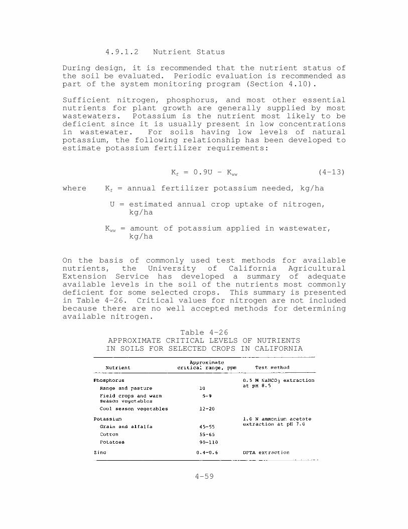
4-59
4.9.1.2 Nutrient Status
During design, it is recommended that the nutrient status ofthe soil be evaluated. Periodic evaluation is recommended aspart of the system monitoring program (Section 4.10).
Sufficient nitrogen, phosphorus, and most other essentialnutrients for plant growth are generally supplied by mostwastewaters. Potassium is the nutrient most likely to bedeficient since it is usually present in low concentrationsin wastewater. For soils having low levels of naturalpotassium, the following relationship has been developed toestimate potassium fertilizer requirements:
K = 0.9U — K (4-13)f ww
where K = annual fertilizer potassium needed, kg/haf
U = estimated annual crop uptake of nitrogen, kg/ha
K = amount of potassium applied in wastewater,ww
kg/ha
On the basis of commonly used test methods for availablenutrients, the University of California AgriculturalExtension Service has developed a summary of adequateavailable levels in the soil of the nutrients most commonlydeficient for some selected crops. This summary is presentedin Table 4-26. Critical values for nitrogen are not includedbecause there are no well accepted methods for determiningavailable nitrogen.
Table 4-26APPROXIMATE CRITICAL LEVELS OF NUTRIENTSIN SOILS FOR SELECTED CROPS IN CALIFORNIA

4-60
4.9.1.3 Soil pH Adjustment
In general, a pH less than 4.2 is too acid for most crops andabove 8.4 is too alkaline for most crops. The optimum pHrange for crop growth depends on the type of crop. Extremesin the soil pH also can affect the performance of an SRsystem or indicate problem conditions. Below pH 6.5, thecapacity of the soil to retain metal is reduced. A soil pHabove 8.5 generally indicates a high sodium content andpossible permeability problems.
The pH of soils can be adjusted by the addition of limingmaterials or acidulating chemicals. A pH adjustment programshould be based on the recommendations of a professionalagricultural consultant or county or state farm adviser.
4.9.1.4 Exchangeable Sodium Control
Soils containing excessive exchangeable sodium are termed“sodic” soils. A soil is considered sodic when thepercentage of the total cation exchange capacity (CEC)occupied by sodium, the exchangeable sodium percentage (ESP),exceeds 15%. High levels of sodium cause low soilpermeability, poor soil aeration, and difficulty in seedlingemergence. Fine-textured soil may be affected at an ESPabove 10%, but coarse-textured soil may not be damaged untilthe ESP reaches about 20%. The ESP should be determined bylaboratory analysis before design if sodic soils are known toexist in the area of the site. Sodic soil conditions may becorrected by adding soluble calcium to the soil to displacethe sodium on the exchange and removing the displaced sodiumby leaching. Advice on correcting sodic soils should beobtained from agricultural consultants or farm advisers.
4.9.1.5 Salinity Control
Salinity control may be necessary in arid climates wherenatural rainfall is insufficient to flush salts from the rootzone. The salinity level of a soil is usually measured onthe basis of the electrical conductivity of an extractsolution from a saturated soil (EC ). Saline soils aree
defined as those yielding an EC value greater than 4,000e
micromhos/cm at 25 C (77 F).E E
Soils that are initially saline may be reclaimed by leaching;however, management of the leachate is often required toprotect ground water quality. The U.S. Department ofAgriculture*s Handbook 60 [45] deals with the diagnosis andimprovement of such soils for agricultural purposes. Thisreference can be used as a practical guide for managing
4-61
saline and saline-sodic soil conditions in arid and semiaridregions.
4.9.2 Crop Management
Because of their substantially different requirements, themanagement of agricultural crops and forest crops arediscussed separately.
4.9.2.1 Agricultural Crop Planting and Harvesting
Local extension services or similar experts should beconsulted regarding planting techniques and schedules. Mostcrops require a period of dry weather before harvest tomature and reach a moisture content compatible withharvesting equipment. Soil moisture at harvest time shouldbe low enough to minimize compaction by harvesting equipment.For these reasons, application should be discontinued well inadvance of harvest. The time required for drying will dependon the soil drainage and the weather. A drying time of 1 to2 weeks is usually sufficient if there is no precipitation.However, advice on this should be obtained from localagricultural experts.
Harvesting of grass crops and alfalfa involves regularcuttings, and a decision regarding the trade-off betweenyield and quality must be made. Advice can be obtained fromlocal agricultural experts. In the northeast and northcentral states, three cuttings per season have beensuccessful with grass crops.
4.9.2.2 Grazing
Grazing of pasture by beef cattle or sheep can provide aneconomic return for SR systems. No health hazard has beenassociated with the sale of the animals for humanconsumption.
Grazing animals return nutrients to the ground in their wasteproducts. The chemical state (organic and ammonia nitrogen)and rate of release of the nitrogen reduces the threat ofnitrate pollution of the ground water. Much of theammonia—nitrogen volatilizes and the organic nitrogen is heldin the soil where it is slowly mineralized to ammonium andnitrate forms. Steer and sheep manure contain approximately20% nitrogen after volatile losses, of which about 40% ismineralized in the first year, 25% in the second, and 6% insuccessive years [41].
In terms of pasture management, cattle or sheep must not beallowed on wet fields to avoid severe soil compaction and

4-62
reduced soil infiltration rates. Wet grazing conditions canalso lead to animal hoof diseases. Pasture rotation shouldbe practiced so that wastewater can be applied immediatelyafter the livestock are removed. In general, a pasture areashould not be grazed longer than 7 days. Typical regrowthperiods between grazings range from 14 to 35 days. Dependingon the period of regrowth provided, one to three waterapplications can be made during the regrowth period.Rotation grazing cycles for 3 to 8 pasture areas are given inTable 4-27. At least 3 to 4 days drying time following anapplication should be allowed before livestock are returnedto the pasture.
Table 4-27GRAZING ROTATION CYCLES FOR
DIFFERENT NUMBERS OF PASTURE AREAS
4.9.2.3 Agricultural Pest Control
Problems with weeds, insects, and plant diseases areaggravated under conditions of frequent water application,particularly when a single crop is grown year after year orwhen no-till practices are used. Most pests can becontrolled by selecting resistant or tolerant crop varietiesand by using pesticides in combination with appropriatecultural practices. State and local experts should beconsulted in developing an overall pest control program fora given situation.
4.9.2.4 Forest Crops
The type of forest crop management practice selected isdetermined by the species mix grown, the age and structure ofthe stand, the method of reproduction best suited and/ordesired for the favored species, terrain, and type ofequipment and technique used by local harvesters. The mosttypical forest management situations encountered in landtreatment are management of existing forest stands,reforestation, and short-term rotation.

4-63
Existing Forest Ecosystems
The general objective of the forest management program is tomaximize biomass production. The compromise between fullyattaining a forest*s growth potential and the need to operateequipment efficiently (distribution and harvesting equipment)requires fewer trees per unit area. These operations willassure maintenance of a high nutrient uptake, particularlynitrogen, by the forest.
For uneven—aged forests, the desired forest composition,structure, and vigor can be best achieved through thinningand selective harvest. However, excessive thinning can maketrees susceptible to wind throw and caution is advised inwindy areas. The objective of these operations would be tomaintain an age class distribution in accordance with theconcept of optimum nutrient storage (see Section 4.3). Themaintenance of fewer trees than normal would permit adequatesunlight to reach the understory to promote reproduction andgrowth of the understory. Thinning should be done initiallyprior to construction of the distribution system and onlyonce every 10 years or so to minimize soil and site damage.
In even-aged forests, trees will all reach harvest age at thesame time. The usual practice is to clear-cut these forestsat harvest age and regenerate a stand by either plantingseedlings, natural seeding, sprouting from stumps (calledcoppice), or a combination of several of the methods. Even-aged stands may require a thinning at an intermediate age tomaintain maximum biomass production. Coniferous forests, ingeneral, must be replanted, whereas hardwood forests can bereproduced by coppice or natural seeding.
The concept of “whole-tree harvesting” should be consideredfor all harvesting operations, whether it be thinning,selection harvest, or clear-cut harvest. Whole-treeharvesting removes the entire standing tree: stem, branches,and leaves. Thus, 100% of the nitrogen accumulated in theaboveground biomass would be removed (see Section 4.3.2.1).
Prescribed fire is a common management practice in manyforests to reduce the debris or slash left on the site duringconventional harvesting methods. During the operation, aportion of the forest floor is burned and nitrogen isvolatilized. Although this represents an immediate benefitin terms of nitrogen removal from the site, the bufferingcapacity that the forest floor offers is reduced and thelikelihood of a nitrate leaching to the ground water isincreased when application of wastewater is resumed.
4-64
Reforestation
Wastewater nutrients often stimulate the growth of theherbaceous vegetation to such an extent that they competewith and shade out the desirable forest species. Herbaceousvegetation is necessary to act as a nitrogen sink while thetrees are becoming established, and therefore, culturalpractices must be designed to control but not eliminate theherbaceous vegetation. As the tree crowns begin to close,the herbaceous vegetation will be shaded and its role in therenovation cycle reduced. Another alternative to control ofthe herbaceous vegetation is to eliminate it completely andreduce the hydraulic and nutrient loading during theestablishment period.
Short-Term Rotation
Short—term rotation forests are plantations of closely spacedhardwood trees that are harvested repeatedly on cycles ofless than 10 years. The key to rapid growth rates andbiomass development is the rootstock that remains in the soilafter harvest and then resprouts. Short-term rotationharvesting systems are readily mechanized because the crop isuniform and relatively small.
Using conventional tree spacings of 2.5 to 4 m (8 to 12 ft),research on systems where wastewater has been applied toshort—term rotation plantations has shown that high growthrates and high nitrogen removal are possible [16]. Plantedstock will produce only 50% to 70% of the biomass producedfollowing cutting and resprouting [47, 48]. If nitrogen andother nutrient uptake is proportional to biomass, the firstrotation from planted stock will not remove as much assubsequent rotations from coppice. Therefore, the initialrotation must receive a reduced nutrient load or otherherbaceous vegetation must be employed for nutrient storage.Alternatively, closer tree spacings may be used to achievedesired nutrient uptake rates during initial rotation.
4.10 System Monitoring
The broad objectives of a monitoring program for an SR systemare to determine if the effluent quality requirements arebeing met, to determine if any corrective action is necessaryto protect the environment or maintain the renovativecapacity of the system, and to aid in system operation. Thecomponents of the environment that need to be observedinclude water quality, the soils receiving wastewater, and insome cases, vegetation growing in soils that are receivingwastewater.
4-65
4.10.1 Water Quality Monitoring
Monitoring of water quality for land application systems canbe more complex than for conventional treatment systemsbecause nonpoint discharges of system effluent are involved.Monitoring of applied wastewater and renovated water qualityis useful for process control. For SR systems, renovatedwater would only be monitored in cases where underdrains areused. Monitoring of receiving waters, surface or groundwater, may be required by regulatory authorities.
In most cases, a water quality monitoring program, includingconstituents to be analyzed and frequency of analysis, willbe prescribed by local regulatory agencies. It may bedesired to monitor additional constituents or parameters forpurposes of crop and soil management.
Ground water monitoring data are difficult to interpretunless sampling wells are located properly and correctsampling procedures are followed. In addition to quality,the depth to ground water should be measured at the samplingwells to determine if the hydraulic response of the aquiferis consistent with what was anticipated. For SR systems, arise in water table levels to the root zone would necessitatecorrective action such as reduced hydraulic loading or addingunderdrainage. The appearance of seeps or perched groundwater tables might also indicate the need for correctiveaction.
4.10.2 Soils Monitoring
In some cases, application of wastewater to the land willresult in changes in soil properties. Results of soilsampling and testing will serve as the basis for decidingwhether or not soil properties should be adjusted by theapplication of chemical amendments. Annual monitoring of thesoil properties described in Section 4.9.1 is sufficient formost systems.
It is recommended that the level of trace elements of concern(see Chapter 9) in the soil be monitored every few years sothat the rate of accumulation can be observed and toxiclevels avoided. Total metal analysis by hot acid digestionis recommended for monitoring and comparison purposes.
4-66
4.10.3 Vegetation Monitoring
Plant tissue analysis is more revealing than soil analysiswith regard to deficient or toxic levels of elements. Ifvisual symptoms of nutrient deficiencies or toxicitiesappear, plant tissue testing can be used for confirmation,and corrective action can be taken. A regular plant tissuemonitoring program can often detect deficiencies or toxicitybefore visual symptoms and damage to the plant occurs.
Nitrate should be determined in forages or leafy vegetablesif there is reason to suspect concentrations which might betoxic to livestock. Detailed information on plant samplingand testing may be found in references [49, 50]. Extensionspecialists or local farm advisers should be consultedregarding plant tissue testing.
4.11 Facilities Design Guidance
The purpose of this section is to provide guidance on aspectsof facilities design that may be unfamiliar to someenvironmental engineers.
! Standard surface irrigation practice is to producelongitudinal slopes of 0.1 to 0.2% with transverseslopes not exceeding 0.3%.
Step 1. Rough grade to 5 cm (0.15 ft) at 30 m (100 ft) grid stations.
Step 2. Finish grade to ±3 cm (0.10 ft) at 30 m (100 ft) grid stations with noreversals in slope between stations.
Step 3. Land plane with a 18 m (60 ft) minimumwheel base, land plane to a “nearperfect” finished grade.
! Access to sprinklers or distribution piping shouldbe provided every 390 m (1,300 ft) for convenientmaintenance.
! Both asbestos-cement and PVC irrigation pipe arerather fragile and require care in handling andinstallation.
! Diaphragm-operated globe valves are recommended forcontrolling flow to laterals.
! All electric equipment should be grounded,especially when associated with center pivotsystems.

4-67
! Automatic controls can be electrically,hydraulically, or pneumatically operated. Solenoidactuated, hydraulically operated (by the wastewater)valves with small orifices will clog from thesolids.
! Valve boxes, 1 m (36 in.) or larger, should be madeof corrugated metal, concrete, fiber glass, or pipematerial. Valve boxes should extend 15 cm (6 in.)above grade to exclude stormwater.
! Low pressure shutoff valves should be used to avoidcontinuous draining of the lowest sprinkler on thelateral.
! Automatic operation can be controlled by timerclocks. It is important that when the timer shutsthe system down for any reason that the field valvesclose automatically and that the sprinkling cyclesresume as scheduled when sprinkling commences. Theclock should not reset to time zero when aninterruption occurs.
! High flotation tires are recommended for landtreatment system vehicles. Recommended soil contactpressures for center pivot machines are presented inTable 4-28.
TABLE 4-28RECOMMENDED SOIL CONTACT PRESSURE
4-68
4.12 References
1. Benham-Blair and Affiliates, Inc. and EngineeringEnterprises, Inc. Long-term Effects of Land Applicationof Domestic Wastewater: Dickinson, North Dakota, SlowRate Irrigation Site. U.S. Environmental ProtectionAgency. EPA-600/2-79-144. August 1979.
2. Demirjian, Y.A. et al. Muskegon County WastewaterManagement System. U.S. Environmental ProtectionAgency. EPA-905/2-80-004. February 1980.
3. Hossner, L.R., et al. Sewage Disposal on AgriculturalSoils: Chemical and Microbiological Implications (SanAngelo, Texas). U.S. Environmental Protection Agency.EPA-600/2-78-131a,b. June 1978.
4. Jenkins, T.F. and A.J. Palazzo. Wastewater Treatment bya Slow Rate Land Treatment System. U.S. Army Corps ofEngineers, Cold Regions Research and EngineeringLaboratory. CRREL Report 81-14. Hanover, NewHampshire. August 1981.
5. Koerner, E.L. and D.A. Haws. Long-Term Effects of LandApplication of Domestic Wastewater: Roswell, New Mexico,Slow Rate Irrigation Site. U.S. EnvironmentalProtection Agency. EPA-600/2-79-647. February 1979.
6. Iskandar, I.K., R.P. Murrmann, and D.C. Leggett.Evaluation of Existing Systems for Land Treatment ofWastewater at Manteca, California and Quincy,Washington. U.S. Army Cold Regions Research andEngineering Laboratory. CRREL Report 77-24. September1977.
7. Nutter, W.L., R.C. Schultz, and G.H. Brister. LandTreatment of Municipal Wastewater on Steep Forest Slopesin the Humid Southeastern United States. Proceedings ofSymposium on Land Treatment of Wastewater. Hanover, NewHampshire. August 20-25, 1978.
8. Stone, R. and J. Rowlands. Long-Term Effects of LandApplication of Domestic Wastewater: Mesa, Arizona,Irrigation Site. U.S. Environmental Protection Agency.EPA-600/2-80-061. April 1980.
9. Enfield, C.G. and B.E. Bledsoe. Kinetic Model forOrthophosphate Reactions in Mineral Soils. EPA-660/2-75-002. U.S. Government Printing Office. June 1975.
4-69
10. Land as a Waste Management Alternative. R.C. Loehr, ed.Ann Arbor Science. Ann Arbor, Michigan. 1977.
11. Overman, A.R. Wastewater Irrigation at Tallahassee,Florida. U.S. Environmental Protection Agency. EPA-600/2-79-151. August 1979.
12. Stone, R. and J. Rowlands. Long-Term Effects of LandApplication of Domestic Wastewater: Camarillo,California, Irrigation Site. U.S. EnvironmentalProtection Agency. EPA-600/2-80-080. May 1980.
13. Tofflemire, T.J. and M. Chen. Phosphate Removal bySands and Soils. In: Land as a Waste ManagementAlternative. Loehr, R.C. (ed). Ann Arbor, Ann ArborScience. 1977.
14. Uiga, A. and R.W. Crites. Relative Health Risks ofActivated Sludge Treatment and Slow Rate Land Treatment.Journal WPCF, 52(12) :2865-2874. December 1980.
15. Pratt, P.F. Quality Criteria for Trace Elements inIrrigation Waters. University of California, Riverside,Department of Soil Science and Agricultural Engineering.1972.
16. National Academy of Science. Water Quality Criteria1972. Ecological Research Series. U.S. EnvironmentalProtection Agency. Report No. R3-73-033. March 1973.
17. U.S. Environmental Protection Agency. PreliminarySurvey of Toxic pollutants at the Muskegon WastewaterManagement System. Robert S. Kerr EnvironmentalResearch Laboratory, Groundwater Research Branch. Ada,Oklahoma. 1977.
18. Hinrichs, D.J. Design of Irrigation Systems forAgricultural Utilization of Effluent. Presented at theCalifornia Water pollution Control Association AnnualConference; Monterey, Calif. May 1, 1980.
19. Smith, W.H. and J.O. Evans. Special Opportunities andProblems in Using Forest Soils for Organic WasteApplication. In: Soils for Management of Organic Wastesand Waste Waters. ASA, CSSA, SSSA, Madison, Wisconsin.pp. 429-451. 1977.
20. Palazzo, A.J., and J.M. Graham. Seasonal Growth andUptake of Nutrients by Orchardgrass Irrigated withWastewater. U.S. Army Cold Regions Research andEngineering Laboratory. CRREL Report 81-8. June 1981.

4-70
21. Duscha, L.A. Dual Cropping Procedure for SlowInfiltration of Land Treatment of Municipal Wastewater.Department of the Army, Engineering Technical Letter No.1110-2-260. March 12, 1981.
22. McKim, H.L., et al. Wastewater Application in ForestEcosystems. CRREL Report 119, Corps of Engineers, U.S.Army. May 1980.
23. USDA Forest Service. Impact of Intensive Harvesting onForest Nutrient Cycling. Northeast Forest ExperimentStation. Broomall, Pa. 1979.
24. Jensen, M.E. (ed.). Consumptive Use of Water andIrrigation Water Requirements. ASCE. ASCE Committee onIrrigation Water Requirements. 1973.
25. Doorenbos, J. and W.O. Pruitt. Guidelines forPredicting Crop Water Requirements. Irrigation andDrainage Paper 24. Presented at United Nations Food andAgriculture Organization. Rome. 1975.
26. Irrigation Water Requirements. Technical Release No.21, U.S. Department of Agriculture, Soil ConservationService. September 1970.
27. Vegetative Water Use in California, 1974. Bulletin No.113-3, State of California Department of WaterResources. April 1975.
28. Booher, L.J. and G.V. Ferry. Estimated Consumptive Useand Irrigation Requirements of Various Crops.University of California Agricultural Extension Service,Bakersfield, Calif. March 10, 1970.
29. Ayers, R.S. Quality of Water for Irrigation, Jour. ofthe Irrigation and Drainage Division, ASCE, Vol. 103,No. IR2. June 1977. pp. 135-154.
30. U.S. Environmental Protection Agency. FacilitiesPlanning, 1982. EPA-430/9-81-012. FRD-25. September1981.
31. Reed, S.C. Treatment/Storage Ponds for Land ApplicationSystems. CRREL Special Report. December 1981.
32. Environmental Protection Agency. Process Design Manualfor Wastewater Treatment Ponds (In Preparation).
33. Bowles, D.S., et al. Coliform Decay Rates in WasteStabilization Ponds, Journal WPCF, 51(l):87-99, January1979.

4-71
34. Sagik, B.P. et al. The Survival of Human EntericViruses in Holding Ponds. Contract Report DAMD 17-75-C-5062. U.S. Army Medical Research and DevelopmentCommand. 1978.
35. Whiting, D.M. Use of Climatic Data in EstimatingStorage Days for Soil Treatment Systems. EnvironmentalProtection Agency, Office of Research and Development.EPA-600/2-76-250. November 1976.
36. Whiting, D.M. Use of Climatic Data in Design of SoilTreatment Systems. EPA-660/2-75-018. EnvironmentalProtection Agency, Office of Research and Development.July 1975.
37. U.S. Department of the Interior, Bureau of Reclamation.Design of Small Dams. Second Edition. U.S. GovernmentPrinting Office. 1973.
38. Booher, L.J. Surface Irrigation. FAO AgriculturalDevelopment Paper No. 95. Food and AgriculturalOrganization of the United Nations. Rome. 1974.
39. Myers, E.A. Design and Operational Criteria for ForestIrrigation Systems. In: Utilization of Municipal SewageEffluent and Sludge on Forest and Disturbed Land. ThePennsylvania State University Press, University Park,Pa. p. 265-272. 1979.
40. Evaluation of Land Application Systems. U.S.Environmental Protection Agency. EPA-430/9-75-001.March 1975.
41. Luthin, J.N. (ed.). Drainage of Agricultural Lands.Madison, American Society of Agronomy. 1957.
42. Van Schilfgaarde, J, ed. Drainage for Agriculture.American Society of Agronomy, Madison, Wisconsin. 1974.
43. Drainage of Agricultural Land. A Practical Handbook forthe Planning, Design, Construction, and Maintenance ofAgricultural Drainage Systems. U.S. Department ofAgriculture, Soil Conservation Service. October 1972.
44. Hart, W.E. Irrigation System Design, Colorado StateUniversity, Department of Agricultural Engineering.Fort Collins, Colorado. November 10, 1975.
45. Richards, L.A. (ed.). Diagnosis and Improvement ofSaline and Alkali Soil. Agricultural Handbook 60. U.S.Department of Agriculture. 1954.

4-72
46. California Fertilizer Assn. Western Fertilizer HandbookSixth Ed. The Interstate Printers and Publishers.1980.
47. Saucier, J.R. Estimation of Biomass Production andRemoval. In: Impact of Intensive Harvesting on ForestNutrient Cycling. College of Environmental Science andForestry, State University of New York, Syracuse, NewYork, p. 172-189. 1979.
48. Steinbeck, K. and C.L. Brown. Yield and Utilization ofHardwood Fiber Grown on Short Rotations. AppliedPolymer Symposium 28: 393-401. 1976.
49. Walsh, L.M. and J.D. Beaton, (eds.). Soil Testing andPlant Analysis. Madison, Soil Science Society ofAmerica. 1973.
50. Melsted, S.W. Soil-Plant Relationships (Some PracticalConsiderations in Waste Management). In: Proceedings ofthe Joint Conference on Recycling Municipal Sludges andEffluents on Land, Champaign, University of Illinois.July 1973. pp. 121-128.
Related Documents