1 Lecture Notes TTK 4190 Guidance, Navigation and Control of Vehicles (T. I. Fossen) Chapter 4 – Hydrostatics 4.1 Restoring Forces for Underwater Vehicles 4.2 Restoring Forces for Surface Vessels 4.3 Load Conditions and Natural Periods 4.4 Seakeeping Analysis 4.5 Ballast Systems Archimedes (287-212 BC) derived the basic laws of fluid statics which are the fundamentals of hydrostatics today. In hydrostatic terminology, the gravitational and buoyancy forces are called restoring forces, and they are equivalent to the spring forces in a mass-damper-spring system. Courtesy to wikipedia.org

Welcome message from author
This document is posted to help you gain knowledge. Please leave a comment to let me know what you think about it! Share it to your friends and learn new things together.
Transcript

1Lecture Notes TTK 4190 Guidance, Navigation and Control of Vehicles (T. I. Fossen)
Chapter 4 – Hydrostatics
4.1 Restoring Forces for Underwater Vehicles 4.2 Restoring Forces for Surface Vessels 4.3 Load Conditions and Natural Periods4.4 Seakeeping Analysis4.5 Ballast Systems
Archimedes (287-212 BC) derived the basic laws of fluid statics which are the fundamentals of hydrostatics today.
In hydrostatic terminology, the gravitational and buoyancy forces are called restoring forces, and they are equivalent to the spring forces in a mass-damper-spring system. Courtesy to wikipedia.org

2Lecture Notes TTK 4190 Guidance, Navigation and Control of Vehicles (T. I. Fossen)
Chapter Goals
The main goal of this chapter is to understand how the restoring and ballast terms in the equations of motion are modelled
• Understand that the restoring forces behave like spring forces in 2nd-order systems and that they are only present in heave, roll and pitch.
• Be able to compute the restoring forces for both floating and submerged vehicles and understand the differences.
• Be able to explain what the “Metacenter” is and explain what we mean by metacenter stability.
• Be able to define the center of flotation and pivot point and explain which point a vehicle roll, pitch and yaw about.
• Understand how load conditions affect hydrostatic quantities such as heave, roll and pitch periods.
• Understand the concepts of manually and automatic pretrimming.
M!! " C!!"! " D!!"! " g!"" " go # # " #wind " #wave

3Lecture Notes TTK 4190 Guidance, Navigation and Control of Vehicles (T. I. Fossen)
M!! " C!!"! " D!!"! " g!"" " go # # " #wind " #wave
M ! MRB "MA - system inertia matrix (including added mass)C!!" ! CRB!!" " CA!!" - Coriolis-centripetal matrix (including added mass)D!!" - damping matrixg!"" - vector of gravitational/buoyancy forces and momentsgo - vector used for pretrimming (ballast control)# - vector of control inputs#wind - vector of wind loads#wave - vector of wave loads
6-DOF equations of motion
Ballast control Gravitational/buoyancy terms
In the derivation of the restoring forces and moments we will distinguish between two cases:
• Section 4.1 Underwater vehicles (ROVs, AUVs and submarines) • Section 4.2 Surface vessels (ships, semisubmersibles and high-speed craft)
Chapter 4 – Hydrostatics
Courtesy to wikipedia.org

4Lecture Notes TTK 4190 Guidance, Navigation and Control of Vehicles (T. I. Fossen)
Underwater VehiclesAccording to the SNAME (1950) it is standard to express the submerged weight of the body and buoyancy force as
= water density= volume of fluid displaced
by the vehiclem = mass of the vessel
including water in freeflooding space
g = acceleration of gravity
4.1 Restoring Forces for Underwater Vehicles
W ! mg, B ! !g!
fgn !
00W
fbn ! !
00B
The weight and buoyancy force can be transformed from NED to BODY by
!
!

5Lecture Notes TTK 4190 Guidance, Navigation and Control of Vehicles (T. I. Fossen)
The sign of the restoring forces and moments and must be changed when moving these terms to the left-hand side of Newton’s 2nd law, e.g. ma = f⟹ma - f = 0
We denote the generalized restoring forces . Notice that the force and moment vectors are multiplied with -1. Consequently, the generalized restoring force in BODY with coordinate origin CO becomes:
where
4.1 Hydrostatics of Submerged Vehiclesmib ! rib!f i
bfib
g!!"
center of buoyancy with respect to the COcenter of gravity with respect to the CO
M!! " C!!"! " D!!"! " g!"" " go # # " #wind " #wave #

6Lecture Notes TTK 4190 Guidance, Navigation and Control of Vehicles (T. I. Fossen)
Main Result: Underwater Vehicles
The 6-DOF gravity and buoyancy forces and moments about the CO are given by
4.1 Hydrostatics of Submerged Vehicles
Copyright © Bjarne Stenberg

7Lecture Notes TTK 4190 Guidance, Navigation and Control of Vehicles (T. I. Fossen)
4.1 Hydrostatics of Submerged Vehicles

8Lecture Notes TTK 4190 Guidance, Navigation and Control of Vehicles (T. I. Fossen)
Example 4.1 (Neutrally Buoyant Underwater Vehicles)Let the distance between the center of gravity CG and the center of buoyancy CB be defined by the vector:
For neutrally buoyant vehicles W = B, and this simplifies to:
An even simpler representation is obtained for vehicles where the CG and CB are located vertically on the z-axis, that is xb = xg and yg = yb. This yields
4.1 Hydrostatics of Submerged Vehicles

9Lecture Notes TTK 4190 Guidance, Navigation and Control of Vehicles (T. I. Fossen)
4.2 Restoring Forces for Surface VesselsFor surface vessels, the restoring forces will depend on the craft's metacentric height, the location of the CG and the CB as well as the shape and size of the water plane. Let Awp denote the water plane area and:
GMT = transverse metacentric height (m)GML = longitudinal metacentric height (m)
The metacentric height GMi where i = {T,L} is the distance between the metacenter Mi and CG.
Definition 4.1 (Metacenter)The theoretical point Mi at which an imaginary vertical line through the CB intersects another imaginary vertical line through a new CB1 created when the body is displaced, or tilted, in the water.

10Lecture Notes TTK 4190 Guidance, Navigation and Control of Vehicles (T. I. Fossen)
A(ζ) is the waterplane area of the vessel as a function of the heave position
4.2 Hydrostatics of Floating VesselsFor a floating vessel at rest, buoyancy and weight are in balance such that
z displacement in heave z = 0 is the equilibrium position
The hydrostatic force in heave is recognized as the difference of the gravitational and buoyancy forces
mg ! !g!
Z ! mg ! !g!" " ""!z""! !!g""!z" #
where the change in displaced water is
CB moves to CB1 when the hull is rotated a roll angle f. CG is fixed for rigid bodies.
z
Awp
A(0) := Awp

11Lecture Notes TTK 4190 Guidance, Navigation and Control of Vehicles (T. I. Fossen)
For conventional rigs and ships with box-shaped walls it can be assumed that
A(0) := Awp
A is constant for small perturbations in z. Hence, the restoring force Z will be linear in z
This is physically equivalent to amass—damper—spring system.
The restoring forces and moments decomposed in BODY
z
Awp
4.2 Hydrostatics of Floating Vessels

12Lecture Notes TTK 4190 Guidance, Navigation and Control of Vehicles (T. I. Fossen)
The moment arms in roll and pitch are and , respectively.Weight and buoyancy act in the z-direction and they form a force pair. Hence,
GMT sin! GML sin !W ! B ! !g!
Neglecting the moment contribution due to !frb (only considering fr
b!implies that the restoring moment becomes:
Copyright © Bjarne Stenberg
4.2 Hydrostatics of Floating Vessels

13Lecture Notes TTK 4190 Guidance, Navigation and Control of Vehicles (T. I. Fossen)
Main Result: Surface Vessels
6-DOF generalized gravity and buoyancy forces
4.2 Hydrostatics of Floating Vessels

14Lecture Notes TTK 4190 Guidance, Navigation and Control of Vehicles (T. I. Fossen)
Linear (Small Angle) Theory for Boxed-Shaped VesselsAssumes that are small such that
sin! ! !, cos! ! 1sin" ! ", cos" ! 1
!, ", z
We have computed the G matrix in CF, that is the center of flotation:
We need to transform this expression to the CO.
4.2 Linear (Small Angle) Theory for Boxed-Shaped Vessels
Equations of motion expressed in the CO

15Lecture Notes TTK 4190 Guidance, Navigation and Control of Vehicles (T. I. Fossen)
The diagonal GCF matrix is based on the assumption that CF is the coordinate origin. If we transform GCF to the CO, two additional coupling terms G35 = G53 appears
G ! G! !
0 0 0 0 0 00 0 0 0 0 00 0 !Zz 0 !Z! 00 0 0 !K" 0 00 0 !Mz 0 !M! 00 0 0 0 0 0
" 0
The coupling terms depend on the location of CF with respect to CO:
4.2 Linear (Small Angle) Theory for Boxed-Shaped Vessels

16Lecture Notes TTK 4190 Guidance, Navigation and Control of Vehicles (T. I. Fossen)
The first moment of areas are zero in the CF since the integrals are computed about the centroid (geometric center) of Awp
The second moment of areas are both positive
For conventional ships the CG and the CB lies on the same vertical line (xb = xg and yb = yg ) such that (Newman 1977)
Usually computed numerically by a 3-D hydrostatic program or approximative formulas
The GM values can be computed for given moment of areas, CG and CB using these formulae
4.2 Linear (Small Angle) Theory for Boxed-Shaped Vessels

17Lecture Notes TTK 4190 Guidance, Navigation and Control of Vehicles (T. I. Fossen)
For small roll and pitch angles the transverse and longitudinal radius of curvature can be approximated by
Moments of area about the waterplane K
M
B
G
IL ! ! !Awpx2dA, IT ! ! !
Awpy2dA
For conventional ships an upper bound on these integrals can be found by considering a rectangular waterplane area Awp= BL where B and L are the beam and length of the hull upper bounded by
IL ! 112 L
3B, IT ! 112 B
3L
4.2 Computation of Metacenter Height for Surface VesselsThe metacenter height M can be computed by using basic hydrostatics
Munro-Smith formula
Morrish’s formula

18Lecture Notes TTK 4190 Guidance, Navigation and Control of Vehicles (T. I. Fossen)
Metacenter M, center of gravity G and center of buoyancy B for a submerged and a floating vessel. The reference is the keel line K.
4.2 Computation of Metacenter Height for Surface Vessels

19Lecture Notes TTK 4190 Guidance, Navigation and Control of Vehicles (T. I. Fossen)
Definition 4.2 (Metacenter Stability)A floating vessel is said to be:
Transverse metacentrically stable if GMT ≥ GMT,min > 0
Longitudinal metacentrically stable if GML ≥ GML,min > 0
The longitudinal stability requirement is easy to satisfy for ships since the pitching motion is quite limited. This corresponds to a large GML value.
The lateral requirement, however, is an important design criterion used to prescribe sufficient stability in roll to avoid that the vessel does not roll around. The vessel must also have damage stability (stability margins) in case of accidents.
Typically, in roll GMT,min > 0.5 m while in pitch GML,min is much larger (more than 100.0 m)
A trade-off between stability and comfort should be made since a large stability margin will result in large restoring forces which can be quite uncomfortable for passengers (the mechanical equivalent is a stiff spring).
4.2 Computation of Metacenter Height for Surface Vessels

20Lecture Notes TTK 4190 Guidance, Navigation and Control of Vehicles (T. I. Fossen)
The load condition will determine the heave, roll and pitch periods of a marine craft. The load condition varies over time (due to loading, offloading, fuel burning, water tanks, etc.)
In a linear system, the natural periods will be independent on the coordinate origin if they are computed using the 6-DOF coupled equations of motion. This is because the eigenvalues of a linear system do not change when applying a similarity transformation.
1-DOF Decoupled Analysis (Natural Periods)The decoupled natural periods should be computed in the CF using the decoupled equations of motion. If not, the results can be very wrong since the eigenvalues of the decoupled equations depend on the coordinate origin as opposed to the 6-DOF coupled system
4.3 Load Conditions and Natural Periods

21Lecture Notes TTK 4190 Guidance, Navigation and Control of Vehicles (T. I. Fossen)
Implicit equations for frequency: Must be solved by iteration since added mass is a function of frequency.
Matlab: fsolve.m (requires optimization toolbox) or fzero.m
4.3 Load Conditions and Natural Periods

22Lecture Notes TTK 4190 Guidance, Navigation and Control of Vehicles (T. I. Fossen)
6-DOF Coupled Analysis (Natural Periods)
A frequency-dependent modal analysis can be used to compute the natural frequencies
Assume that the floating vessel carries out harmonic oscillations such that
The natural frequencies are computed for the undamped system which gives
This is a frequency-dependent eigenvalue problem
4.3 Computation of Natural Periods in a 6-DOFCoupled System
The eigenvalues must be computed for all frequencies
M!!" ! MRB " A!!"D!!" ! B!!" " BV!!" " Kd
G ! C " Kp
# # #
!G ! !2M"!# ! j!D"!#$a ! 0 #
D!!" ! 0

23Lecture Notes TTK 4190 Guidance, Navigation and Control of Vehicles (T. I. Fossen)
4.3 Computation of Natural Periods in a 6-DOFCoupled System

24Lecture Notes TTK 4190 Guidance, Navigation and Control of Vehicles (T. I. Fossen)
4.3 Load Conditions and Natural Periods
R55 ! R66 ! 0.25LppR44 ! 0.37B
Offshore vessels
R55 ! R66 ! 0.27LppR44 ! 0.35BTankers:
The roll period clearly depend on the load condition—i.e. added moment of inertia A44, mass m radius of gyration R44 and metacentric height GMT
Radius of gyration

25Lecture Notes TTK 4190 Guidance, Navigation and Control of Vehicles (T. I. Fossen)
4.3 Load Conditions and Natural Periods
0 5 10 15T (m)
0
5
10
T 3 (s)
Heave period T3 (s) as a function of T (m)
Theave = sqrt( 2*T/g )Design: T = 10.00 m, T = 9.67 s
0 2 4 6 8 10 12GMT (m)
10
20
30
40
T 4 (s)
Roll period T4 (s) as a function of GMT (m)
kroll = 0.41Design: GMT = 9.98 m, T4 = 12.85 s
0 100 200 300 400 500 600GML (m)
0
20
40
60
T 5 (s)
Pitch period T5 (s) as a function of GML (m)
kpitch = 1.37Design: GML = 470.92 m, T5 = 9.11 s
Heave, roll and pitch periods for varying draft and metacenter
The design values (asterisks) are computed using the WAMIT data for the operational condition.
Matlab:

26Lecture Notes TTK 4190 Guidance, Navigation and Control of Vehicles (T. I. Fossen)
4.3 Free-Surface EffectsMany ships are equipped liquid tanks like ballast and anti-roll tanks. A partially filled tank is known as a slack tank and in these tanks the liquid can move and endanger the ship stability.
The reduction of metacentric height GMT caused by the liquids in slack tanks is known as the free-surface effect.
The mass of the liquid or the location of the tanks play no role, only the moment of inertia of the surface affects stability.
The effective metacentric height corrected for slack tanks filled with sea water is
Free-surface-correction (FSC) for N tanks
Rectangular tank with length l in the x direction and width b in the y direction
FSC ! !r!1
N!m ir #
ir ! lb3
12 #
ir is the moment of inertia of the water surface
The free surface effect is a mechanism which can cause a watercraft to become unstable and capsize.
27Lecture Notes TTK 4190 Guidance, Navigation and Control of Vehicles (T. I. Fossen)
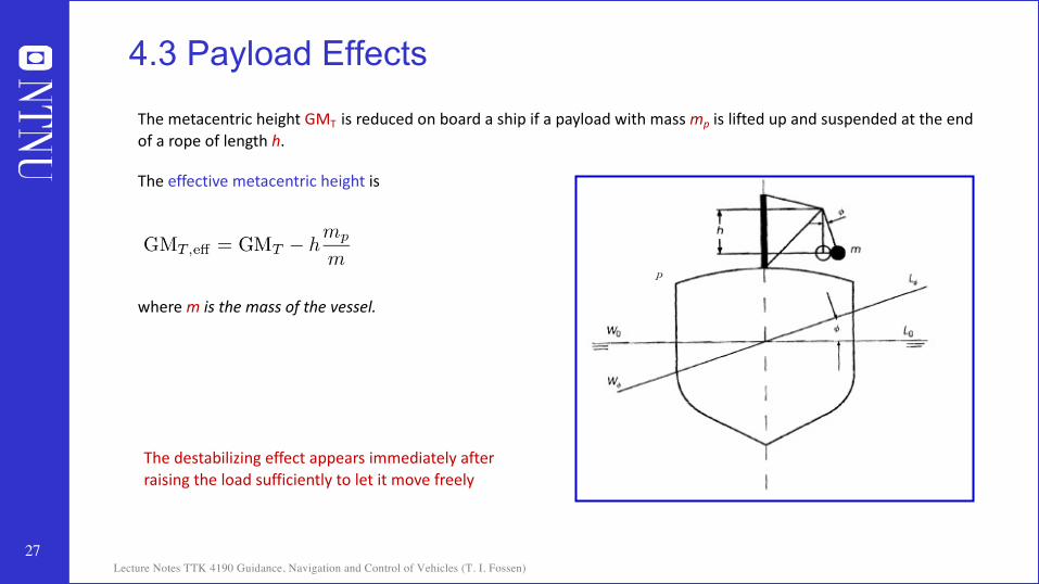
4.3 Payload Effects
The metacentric height GMT is reduced on board a ship if a payload with mass mp is lifted up and suspended at the end of a rope of length h.
The effective metacentric height is
where m is the mass of the vessel.
The destabilizing effect appears immediately after raising the load sufficiently to let it move freely
p

28Lecture Notes TTK 4190 Guidance, Navigation and Control of Vehicles (T. I. Fossen)
4.4 Seakeeping AnalysisIn the design of ships and ocean structures, the wave-induced motions are of great importance to the assessment of the comfort and safety of the crew and the passengers.
Seakeeping analyses should be performed to estimate seakeeping ability or seaworthiness, that is how well-suited a marine craft is to conditions when underway.
This section presents methods for computation of the heave, roll and pitch responses in regular waves as well as resonance analyses.
Copyright © Bjarne Stenberg

29Lecture Notes TTK 4190 Guidance, Navigation and Control of Vehicles (T. I. Fossen)
Relative damping ratio
Solution (no forcing)
1) Will a ship oscillate at the natural frequency ωn when excited by regular waves?
2) Will the ship oscillate at 6 different frequencies when moving in 6 DOFs?
Natural frequency (undamped angular frequency)
For ships we add waves as forcing
4.4 Harmonic Oscillator without Forcing
k z

30Lecture Notes TTK 4190 Guidance, Navigation and Control of Vehicles (T. I. Fossen)
4.4 Harmonic Oscillator with Sinusoidal Forcing
Answer to questions: Marin craft oscillates at ω and not ωn in all DOFs when sufficient excited (i.e., for a fully developed sea with peak frequency ω)
Before “fully excited” the craft can oscillate with different frequencies in all 6 DOFs
Steady-state variation of amplitude with relative frequency ω/ωn and damping ζ of a forced harmonic oscillator (resonance at ω/ωn = 1.0)
Impedance and phase
Solving Zm = 0 gives the resonant frequency
ω/ωn

31Lecture Notes TTK 4190 Guidance, Navigation and Control of Vehicles (T. I. Fossen)
4.4 Steady-State Heave, Roll and Pitch Responses in Regular Waves
where k is the wave number and d is the water depth
Encounter frequency
Wave frequency

32Lecture Notes TTK 4190 Guidance, Navigation and Control of Vehicles (T. I. Fossen)
4.4 Steady-State Heave, Roll and Pitch Responses in Regular Waves
0 0.5 1 1.5 2 2.5we/wn
0
2
4
6
8
10
12Amplitude = wi
2 / (Zm we)
Heave: damping z3 = 0.41, nat. frequency w3 = 0.99Roll: damping z4 = 0.05, nat. frequency w4 = 0.58Roll: damping z4 = 0.10, nat. frequency w4 = 0.58Pitch: damping z5 = 0.54, nat. frequency w5 = 1.03MSS Matlab script:
ExResonance.m
Data set:>> load supply
As expected, roll is the critical DOF for which the amplitude of the roll angle φ is significantly amplified when ωe/ωn = 1.0. The natural frequency is ωn = ω4 = 0.58 rad/s. This corresponds to regular waves with a period T4 = 10.9 s, which are likely to happen. The relative damping ratio ζ4 = 0.05 in roll for the MSS supply vessel is quite low, while GMT = 2.14 m gives sufficient stability.

33Lecture Notes TTK 4190 Guidance, Navigation and Control of Vehicles (T. I. Fossen)
4.4 Steady-State Heave, Roll and Pitch Responses in Regular Waves
0 5 10 15 20time (s)
-2
-1
0
1
2
Steady-state responses for a = 2.0 m and beta = 75.0 deg
Heave (m)Roll (deg)Pitch (deg)

34Lecture Notes TTK 4190 Guidance, Navigation and Control of Vehicles (T. I. Fossen)
M !! " C!!"! " D!!"! " g!"" " go # # " #wind " #wavew
#
A floating or submerged vessel can be pretrimmed by pumping water between the ballast tanks of the vessel. This implies that the vessel can be trimmed in heave, pitch and roll
z ! zd, ! ! !d, " ! "d Three modes with restoring force and moments
Steady-state solution
XX X
!d ! !!,!,!,zd,!d, "d,!"!where
The ballast vector go is computed by using hydrostatic analyses (steady-state condition).
main equation for ballast computationsg!!d" ! go " w #
4.5 Ballast Systems

35Lecture Notes TTK 4190 Guidance, Navigation and Control of Vehicles (T. I. Fossen)
Consider a marine craft with n ballast tanks of volumes Vi ≤ Vi,max (i=1,…,n)
For each ballast tank the water volume is given by the integral
Vi!hi" ! !o
hi Ai!h"dh " Aihi, (Ai!h" ! constant)
Zballast ! !i!1n Wi ! !g!i!1
n Vi
The gravitational force in heave due to Wi is
Copyright © Bjarne Stenberg
4.5 Ballast Systems

36Lecture Notes TTK 4190 Guidance, Navigation and Control of Vehicles (T. I. Fossen)
4.5 Ballast Systems
Restoring moments due to the heave force Zballast
Ballast tank locations with respect to the CO
Kballast ! !g!i!1
n
y iVi
Mballast ! "!g!i!1
n
x iVi
#
#
Resulting ballast model

37Lecture Notes TTK 4190 Guidance, Navigation and Control of Vehicles (T. I. Fossen)
G!3,4,5"!d!3,4,5" ! go!3,4,5" " 0
#
!Zz 0 !Z!0 !K" 0
!Mz 0 !M!
zd"d!d
! #g
!"i"1n Vi
!"i"1n yiVi
"i"1n xiVi
" 0
#
Trimming is usually done under the assumptions that and are small such
Reduced-order system (heave, roll, and pitch)
!d !d
g!!d" ! G!d
Steady-state condition:
This is a set of linear equations where the volumes Vi can be found by assuming that w = 0 (zero disturbances)
G!3,4,5" !
!Zz 0 !Z!0 !K" 0
!Mz 0 !M!
go!3,4,5" ! !g
!"i!1n Vi
!"i!1n yiVi
"i!1n xiVi
!d!3,4,5" ! #zd,!d,"d $!
w!3,4,5" ! #w3,w4,w5$!
4.5 Static Conditions for Trim and Heel

38Lecture Notes TTK 4190 Guidance, Navigation and Control of Vehicles (T. I. Fossen)
Assume that the disturbances in heave, roll, and pitch have zero means. Consequently:
and
!Zz 0 !Z!0 !K" 0
!Mz 0 !M!
zd"d!d
!
#g"i!1n Vi " w3
#g"i!1n yiVi " w4
!#g"i!1n xiVi " w5
! ! H!y ! H"!HH""!1y
The water volumes Vi is found by using the pseudo-inverse:
!g1 ! 1 1y1 ! yn!1 yn!x1 ! !xn!1 !xn
V1V2"
Vn
!
!Zzzd ! Z""d!K##d!Mzzd ! M""d
H! ! y"
#
w!3,4,5" ! #w3,w4,w5$! ! 0
Courtesy to SeaLaunch
4.5 Static Conditions for Trim and Heel

39Lecture Notes TTK 4190 Guidance, Navigation and Control of Vehicles (T. I. Fossen)
4.5 Static Conditions for Trim and HeelExample 4.3(Semi-Submersible Ballast Control) Consider a semi-submersible with
4 ballast tanks located atIn addition, yz-symmetry implies that
P P
PP
P P
V1 V2
V4 V3
xb
yb
O
p1
p2
p3+
+
+
r1b ! !!x,!y", r2b ! !x, !y",r3b ! !x, y",r4b ! !!x,y"Z! ! Mz ! 0
H ! !g1 1 1 1!y !y y yx !x !x x
y !
!Zzzd!K""d!M##d
!
!gAwp!0"zd!g"GMT"d!g"GML#d
! "
V1V2V3V4
! 14!g
1 ! 1y 1x
1 ! 1y ! 1x1 1
y ! 1x1 1
y1x
!gAwp!0"zd!g"GMT"d!g"GML#d
! ! H!y ! H"!HH""!1y
Inputs: zd ,!d," d

40Lecture Notes TTK 4190 Guidance, Navigation and Control of Vehicles (T. I. Fossen)
In the static analyses it was assumed that w{3,4,5} = 0. This assumption can be relaxed by using feedback.
The closed-loop dynamics of a PID controlled water pump can be described by a 1st-order model with amplitude saturation
Tj (s) is a positive time constantpj (m³/s) is the volumetric flow rate pump jpd
j is the pump set-point.
The water pump capacity is different for positive and negativeflow directions
4.5 Automatic Ballast Control Systems
Tjp! j " pj # sat!pdj"
sat!pdj" !
pj,max" pj # pj,max"
pdj pj,max! " pdj " pj,max"
pj,max! pdj $ pj,max!

41Lecture Notes TTK 4190 Guidance, Navigation and Control of Vehicles (T. I. Fossen)
Example 4.4 (Semi-Submersible Ballast Control, Continues): The water flow model corresponding to the figure is:
4.5 Automatic Ballast Control Systems
V! 1 " !p1V! 2 " !p3V! 3 " p2 # p3V! 4 " p1 ! p2
Tp! " p ! sat!pd"#! ! Lp
# #
! "
V1V2V3V4
, p "
p1p2p3
, L "
!1 0 00 0 !10 1 11 !1 0
Copyright © Bjarne Stenberg

42Lecture Notes TTK 4190 Guidance, Navigation and Control of Vehicles (T. I. Fossen)
Feedback control system
Hpid!s" ! diag#h1,pid!s", h2,pid!s", . . . ,hm,pid!s"$
Tp! " p ! sat!pd"#! ! Lp
# #
Equilibrium equation
Dynamics
4.5 Automatic Ballast Control Systems
G!3,4,5"!!3,4,5" ! go!3,4,5"#"$ " w!3,4,5" #
pd ! Hpid!s"G#3,4,5$ !d#3,4,5$ ! !#3,4,5$ #
Courtesy to SeaLaunch

43Lecture Notes TTK 4190 Guidance, Navigation and Control of Vehicles (T. I. Fossen)
An example of a highly sophisticated pretrimming system is the SeaLaunch trim and heel correction system (THCS)
4.5 Automatic Ballast Control SystemsSeaLaunch:
This system is designed such that the platform maintains constant roll and pitch angles during changes in weight. The most critical operation is when the rocket is transported from the garage on one side of the platform to the launch pad. During this operation the water pumps operate at their maximum capacity to counteract the shift in weight.
A feedback system controls the pumps to maintain the correct water level in each of the legs during transportation of the rocket
Courtesy to SeaLaunch

44Lecture Notes TTK 4190 Guidance, Navigation and Control of Vehicles (T. I. Fossen)
4.5 Automatic Ballast Control Systems
SeaLaunch Trim and Heel Correction System (THCS)
Courtesy to SeaLaunch

45Lecture Notes TTK 4190 Guidance, Navigation and Control of Vehicles (T. I. Fossen)
4.5 Automatic Ballast Control Systems
Courtesy to SeaLaunch

46Lecture Notes TTK 4190 Guidance, Navigation and Control of Vehicles (T. I. Fossen)
SMMarine Segment
4.5 Automatic Ballast Control Systems
Courtesy to SeaLaunch

47Lecture Notes TTK 4190 Guidance, Navigation and Control of Vehicles (T. I. Fossen)
0 187.5 375 562.5 750 937.5 1125 1312.5 150021.51
0.50
0.51
1.52
2.53
3.54
4.55
5.56
Roll and pitch during launch time (secs)
roll
and
pitc
h (d
eg)
420 430 440 450 460 4702
0
2
4
6
Measured pitch during launch
time (secs)
Pitc
h ang
le (d
eg)
4.21
0.95
A 1< >jp
470420 jp 20 10 0 10 20 302
0
2
4
6
Calculated pitch motionstime (secs)
pitch
angl
e (de
g)
4.326
0.202
Z 4< >l
180p
.
29.77515 Z 1< >l
roll
pitch
Roll and pitch angles during lift-off
CNN 10th October 1999
4.5 Automatic Ballast Control Systems
Courtesy to SeaLaunch

48Lecture Notes TTK 4190 Guidance, Navigation and Control of Vehicles (T. I. Fossen)
Chapter Goals - Revisited
The main goal of this chapter is to understand how the restoring and ballast terms in the equations of motion are modelled
• Understand that the restoring forces behave like spring forces in 2nd-order systems and that they are only present in heave, roll and pitch.
• Be able to compute the restoring forces for both floating and submerged vehicles and understand the differences.
• Be able to explain what the “Metacenter” is and explain what we mean by metacenter stability.
• Be able to define the center of flotation and pivot point and explain which point a vehicle roll, pitch and yaw about.
• Understand how load conditions affect hydrostatic quantities such as heave, roll and pitch periods.
• Understand the concepts of manually and automatic pretrimming.
M!! " C!!"! " D!!"! " g!"" " go # # " #wind " #wave
Related Documents