4 FUEL SYSTEM/CARBURETION 4.1 CHAPTER 4 FUEL SYSTEM/CARBURETION Exploded View, Mikuni BST 34 Carburetor 4.2 ... Fuel Pump Exploded View 4.3 ................. Fuel Tank Asm. Exploded View 4.4 ............ Fuel Flow Diagram 4.4 ....................... Special Tools & Jetting Guidelines 4.5 ......... Carburetor Jetting 4.5 ........................ Main Jet / Pilot Jet Part Numbers 4.5 ........... CV Carburetor System Function (4 Cycle) 4.6 ... CV Carburetor Vent System (4 Cycle) 4.6 ....... CV Carburetor Operation 4.6-4.7 .................. Disassembly Notes, CV Carburetor 4.8-4.9 ......... Cleaning, CV Carburetor 4.9 .................. Inspection, CV Carburetor 4.10 ................. Assembly, CV Carburetor 4.10-4.11 ................. Float Adjustment, CV Carburetor 4.11 ........... Needle & Seat Leakage Test 4.11 ............... Fuel Level 4.12 ............................... Fuel Pump Service 4.12 ....................... Troubleshooting 4.13 ..........................

Welcome message from author
This document is posted to help you gain knowledge. Please leave a comment to let me know what you think about it! Share it to your friends and learn new things together.
Transcript

4
FUEL SYSTEM/CARBURETION
4.1
CHAPTER 4
FUEL SYSTEM/CARBURETION
Exploded View, Mikuni BST 34 Carburetor 4.2. . .
Fuel Pump Exploded View 4.3. . . . . . . . . . . . . . . . .
Fuel Tank Asm. Exploded View 4.4. . . . . . . . . . . .
Fuel Flow Diagram 4.4. . . . . . . . . . . . . . . . . . . . . . .
Special Tools & Jetting Guidelines 4.5. . . . . . . . .
Carburetor Jetting 4.5. . . . . . . . . . . . . . . . . . . . . . . .
Main Jet / Pilot Jet Part Numbers 4.5. . . . . . . . . . .
CV Carburetor System Function (4 Cycle) 4.6. . .
CV Carburetor Vent System (4 Cycle) 4.6. . . . . . .
CV Carburetor Operation 4.6-4.7. . . . . . . . . . . . . . . . . .
Disassembly Notes, CV Carburetor 4.8-4.9. . . . . . . . .
Cleaning, CV Carburetor 4.9. . . . . . . . . . . . . . . . . .
Inspection, CV Carburetor 4.10. . . . . . . . . . . . . . . . .
Assembly, CV Carburetor 4.10-4.11. . . . . . . . . . . . . . . . .
Float Adjustment, CV Carburetor 4.11. . . . . . . . . . .
Needle & Seat Leakage Test 4.11. . . . . . . . . . . . . . .
Fuel Level 4.12. . . . . . . . . . . . . . . . . . . . . . . . . . . . . . .
Fuel Pump Service 4.12. . . . . . . . . . . . . . . . . . . . . . .
Troubleshooting 4.13. . . . . . . . . . . . . . . . . . . . . . . . . .
FUEL SYSTEM/CARBURETION
4.2
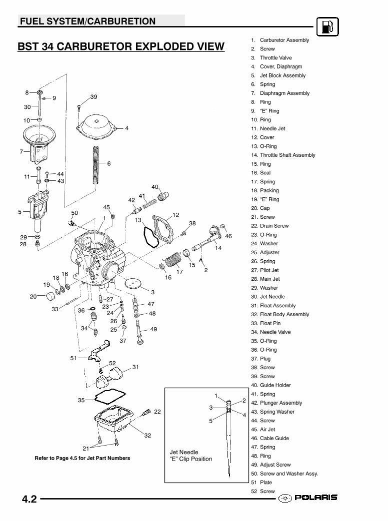
BST 34 CARBURETOR EXPLODED VIEW1. Carburetor Assembly
2. Screw
3. Throttle Valve
4. Cover, Diaphragm
5. Jet Block Assembly
6. Spring
7. Diaphragm Assembly
8. Ring
9. “E” Ring
10. Ring
11. Needle Jet
12. Cover
13. O-Ring
14. Throttle Shaft Assembly
15. Ring
16. Seal
17. Spring
18. Packing
19. “E” Ring
20. Cap
21. Screw
22. Drain Screw
23. O-Ring
24. Washer
25. Adjuster
26. Spring
27. Pilot Jet
28. Main Jet
29. Washer
30. Jet Needle
31. Float Assembly
32. Float Body Assembly
33. Float Pin
34. Needle Valve
35. O-Ring
36. O-Ring
37. Plug
38. Screw
39. Screw
40. Guide Holder
41. Spring
42. Plunger Assembly
43. Spring Washer
44. Screw
45. Air Jet
46. Cable Guide
47. Spring
48. Ring
49. Adjust Screw
50. Screw and Washer Assy.
51 Plate
52 Screw
Refer to Page 4.5 for Jet Part Numbers
12
3
45
Jet Needle“E” Clip Position
1
2
3
4
5
6
7
89
10
11
1213
14
15
161716
1819
20
21
22
2324
25
26
27
2829
30
31
32
33
34
35
36
37
38
39
40
4142
4344
45
46
47
48
49
50
5152

FUEL SYSTEM/CARBURETION
4.3
FUEL PUMP EXPLODED VIEW
32
1
5
54
1. Fuel Pump Assembly2. Diaphragm, Gasket Set3. Screw and Washer Assembly4. Screw and Washer Assembly5. Screw and Washer Assembly6. Pressure Regulator7. Fuel Inlet8. Fuel Outlet
6
8
7
FUEL SYSTEM/CARBURETION
4.4
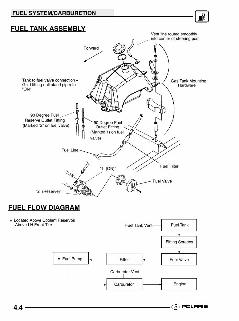
FUEL TANK ASSEMBLY
Fuel Tank
Fuel Valve
Engine
FilterFuel Pump
Carburetor
Fuel Tank Vent
Carburetor Vent
Fitting Screens
�
FUEL FLOW DIAGRAM
Vent line routed smoothlyinto center of steering post
Forward
“1 (ON)”
“2 (Reserve)”
Tank to fuel valve connection --Gold fitting (tall stand pipe) to“ON”
Gas Tank MountingHardware
Fuel Valve
90 Degree FuelOutlet Fitting
90 Degree Fuel
Reserve Outlet Fitting
Fuel Filter
Fuel Line
(Marked “2” on fuel valve)
(Marked 1) on fuel
valve)
� Located Above Coolant ReservoirAbove LH Front Tire

FUEL SYSTEM/CARBURETION
4.5
SPECIAL TOOLSPART NUMBER TOOL
DESCRIPTION
2870975 Mity Vac�Pressure Test Tool
2872314 Carburetor FloatAdjustment Tool
WARNING
Gasoline is extremely flammable and explosive undercertain conditions.
Always stop the engine and refueloutdoors or in a well ventilated area.
Do not overfill the tank. The tank is atfull capacity when the fuel reaches thebottom of the filler neck. Leave roomfor expansion of fuel.
Never start the engine or let it run in anenclosed area. Gasoline powered engineexhaust fumes are poisonous and cancause loss of consciousness and death ina short time.
Never drain the float bowl when the engineis hot. Severe burns may result.
Do not smoke or allow open flames orsparks in or near the area where refuelingis performed or where gasoline is stored.
If you get gasoline in your eyes or if youshould swallow gasoline, seek medicalattention immediately.
If you spill gasoline on your skin or clothing,immediately washwith soap and water andchange clothing.
JETTING GUIDELINES
Changes in altitudeand temperature affect air density,which is essentially the amount of oxygenavailable forcombustion. In low elevations and cold temperatures,the air is more dense and hasmore oxygen. In higherelevations and higher temperatures, the air is lessdense with reduced oxygen.
Polaris ATV Carburetors are calibrated for an altitudeof 0-6000 ft. (0-1800 meters) and ambienttemperatures between +40 and +80� F (+5� to +26�C). Carburetors must be re-calibrated if operated
outside this temperature and/or altitude range. Thejetting installed in production is not intended for allaltitudes and/or temperatures. In addition, air screw/ pilot screw adjustments and PVT adjustments maybe required to suit operating conditions.
CARBURETOR JETTING
CAUTION:
A main jet that is too small will cause a leanoperating condition resulting in serious enginedamage. Select the correct main jet carefully forelevation and temperature according to thecharts in the Specifications section or in theOwner’s Safety andMaintenanceManual for eachparticular model.
IMPORTANT: The following guidelines must befollowed when establishing a main jet setting:
1. Select the lowest anticipated temperature atwhich the machine will be operated.
2. Determine the lowest approximate altitude atwhich the machine will be operated.
3. Select the correct main jet from the chart on pageon the Specifications page.
4. Clutching changes may also be required forchanges in elevation. Refer to clutching chart inthe Specifications section for recommendations.
MIKUNI JET PART NUMBERS
Main JetsJet Number Part Number
112.5 3130554115 3130555117.5 3130556120 3130557122.5 3130558125 3130559127.5 3130560130 3130561132.5 3130562135 3130563137.5 3130564140 3130527142.5 3130566145 3130567147.5 3130568150 3130569152.5 3130570155 3130571157.5 3130572160 3131141162.5 3131142165 3131143167.5 3131144170 3131145
Jet Number Part Number
40.0 3130624
42.5 3130526
50.0 3131132
Pilot Jets

FUEL SYSTEM/CARBURETION
4.6
CV CARBURETOR SYSTEM
FUNCTION
Carburetor Component Function
System Main
Components
Main
Function
Main
Affect
FloatSystem
(Level Control)
Inlet Pipe,Needle andSeat, Float,Float Pin
Maintainsspecifiedfuel level infloat cham-ber (carbu-retor floatbowl)
All systemsAll throttleranges
Venting Passages inCarburetor,Vent linesto frame
Suppliesatmosphericpressure tofloat cham-ber
All systemsAll throttleranges
Starter(Choke/En-richment)
Choke Lever,Cable, Plung-er, ReturnSpring, CarbPassages(Starter Jet,Starter BleedPipe)
Suppliesadditionalfuel air mix-ture neces-sary for coldstarting
All throttlerangesGreatesteffect atlow throttlesettingsand idle
Pilot(Idle System)
Pilot Jet/Passage-ways, Pilot-MixtureScrew withSpringWasher andSealing O-Ring, By-pass Ports(BehindThrottlePlate), PilotAir Jet, PilotOutlet,ThrottlePlate
Primarilysupplies fuelat idle andlow throttlepositions
Mainly idleto 1/4throttleMinimal ef-fect after1/2 throttle
MainSystem
Main Jet,Main Air Jet,Main AirPassage,Needle Jet,Jet Needle,VacuumSlide,ThrottlePlate
Suppliesfuel at mid-range andhigh throttlesettings.
1/4 to fullthrottle
VENT SYSTEMS - CV
CARBURETOR
The carburetor float bowl vent lines supplyatmospheric pressure to the float bowl. The linesmust be free of kinks, restrictions and be properlyrouted. This allows fuel to flow in the proper amountand prevents contaminants from entering thecarburetor.
MIKUNI CV CARB
OPERATION
The constant velocity carburetor incorporates amechanically operated throttle plate and a vacuumcontrolled slide valve (vacuum slide). The venturicross-sectional area in the carburetor bore isincreased or decreased automatically by the vacuumslide, which moves according to the amount ofnegative pressure (less than atmospheric) present inthe venturi.
A diaphragm attached to the top of the vacuum slideis sealed to the slide and to the carburetor bodyforming two chambers. The chamber above thediaphragm is connected to the venturi area by adrilledorifice in the center of the vacuum slide. The chamberbelow the diaphragm is vented to atmosphericpressure by a passage on the air box side of thecarburetor. A spring, installed in the center of thevacuum slide, dampens the slide movement andassists the return of the slide.
= Air Flow = Low Pressure
Air BoxPressure
FromAir Box
Venturi
ThrottlePlate
Diaphragm
VacuumSlide
Low PressureFrom Venturi

FUEL SYSTEM/CARBURETION
4.7
CARBURETOR OPERATION CONT’D
When the throttle plate is opened and engine speedbegins to increase, the pressure in the venturi (andtherefore in the chamber above the diaphragm)becomes significantly lower than atmospheric.Atmospheric pressure in the chamber below thediaphragm forces the diaphragm upward, raising theslide against spring pressure. When the pressureabove and below the diaphragm are nearly equal, theslide moves downward under spring pressure.Raising or lowering the slide increases or decreasesthe cross sectional area in the venturi, and thereforethe air velocity in the venturi is kept relatively constant.This provides improved fuel atomization andoptimumfuel/air ratio.
= Air Flow = Low Pressure
Low PressureFrom Venturi
FromAir Box
ThrottlePlate
Diaphragm
VacuumSlide
Venturi
Note: Diagrams are for explanation of theory only, and are not true
representations of Mikuni BST carburetor.
PILOT (IDLE AND SLOW)
SYSTEM
This system supplies fuel during engine operationwith throttle valve closed (1) or slightly opened. Thefuel from float chamber (2) is metered by pilot jet (3)where it mixes with air coming in through pilot air jet(4). The mixture then goes up through pilot passageto pilot screw (5). A part of the mixture is dischargedinto the main bore out of bypass ports (6). Theremainder is then metered by pilot screw anddischarged into the main bore through pilot outlet (7).
4
1
6
7
5
2
3
STARTER SYSTEM (CHOKE
OR ENRICHMENT)
When the choke cable (1) is activated, the starterplunger (5) is lifted off the seat.
15
8
6
4
2
3
7
Fuel is drawn into the starter circuit from the floatchamber (2) through the starter jet (3). Starter jetmeters this fuel, which then flows into starter pipe (4)and mixes with the air (7) coming from the floatchamber. The mixture, rich in fuel content, reachesstarter plunger and mixes again with the air comingthrough a passage (8) extending from underneath thediaphragm. The rich fuel/air mixture for starting isdischarged through starter outlet (6) in the the mainbore.
FUEL SYSTEM/CARBURETION
4.8
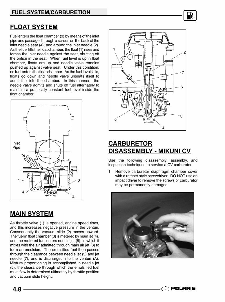
FLOAT SYSTEM
Fuel enters the float chamber (3) bymeans of the inletpipe andpassage, througha screenon theback of theinlet needle seat (4), and around the inlet needle (2).As the fuel fills the float chamber, the float (1) risesandforces the inlet needle against the seat, shutting offthe orifice in the seat. When fuel level is up in floatchamber, floats are up and needle valve remainspushed up against valve seat. Under this condition,no fuel enters the float chamber. As the fuel level falls,floats go down and needle valve unseats itself toadmit fuel into the chamber. In this manner, theneedle valve admits and shuts off fuel alternately tomaintain a practically constant fuel level inside thefloat chamber.
InletPipe
1
42
3
MAIN SYSTEM
As throttle valve (1) is opened, engine speed rises,and this increases negative pressure in the venturi.Consequently the vacuum slide (2) moves upward.The fuel in float chamber (3) ismeteredbymain jet (4),and the metered fuel enters needle jet (5), in which itmixes with the air admitted through main air jet (6) toform an emulsion. The emulsified fuel then passesthrough the clearance between needle jet (5) and jetneedle (7), and is discharged into the venturi (A).Mixture proportioning is accomplished in needle jet(5); the clearance through which the emulsified fuelmust flow is determined ultimately by throttle positionand vacuum slide height.
1
A
5
4
3
6
7
2
CARBURETOR
DISASSEMBLY - MIKUNI CV
Use the following disassembly, assembly, andinspection techniques to service a CV carburetor.
1. Remove carburetor diaphragm chamber coverwith a ratchet style screwdriver. DO NOT use animpact driver to remove the screws or carburetormay be permanently damaged.
FUEL SYSTEM/CARBURETION
4.9
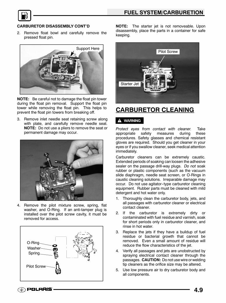
CARBURETOR DISASSEMBLY CONT’D
2. Remove float bowl and carefully remove thepressed float pin.
Support Here
NOTE: Be careful not to damage the float pin towerduring the float pin removal. Support the float pintower while removing the float pin. This helps toprevent the float pin towers from breaking off.
3. Remove inlet needle seat retaining screw alongwith plate, and carefully remove needle seat.NOTE: Do not use a pliers to remove the seat orpermanent damage may occur.
4. Remove the pilot mixture screw, spring, flatwasher, and O-Ring. If an anti-tamper plug isinstalled over the pilot screw cavity, it must beremoved for access.
O-Ring
Washer
Spring
Pilot Screw
NOTE: The starter jet is not removeable. Upondisassembly, place the parts in a container for safekeeping.
Starter Jet
Pilot Screw
CARBURETOR CLEANING
WARNING
Protect eyes from contact with cleaner. Takeappropriate safety measures during theseprocedures. Safety glasses and chemical resistantgloves are required. Should you get cleaner in youreyes or if you swallow cleaner, seek medical attentionimmediately.
Carburetor cleaners can be extremely caustic.Extended periods of soaking can loosen the adhesivesealer on the passage drill-way plugs. Do not soakrubber or plastic components (such as the vacuumslide diaphragm, needle seat screen, or O-Rings incaustic cleaning solutions. Irreparable damage mayoccur. Do not use agitator--type carburetor cleaningequipment. Rubber parts must be cleaned with milddetergent and hot water only.
1. Thoroughly clean the carburetor body, jets, andall passages with carburetor cleaner or electricalcontact cleaner.
2. If the carburetor is extremely dirty orcontaminated with fuel residue and varnish, soakfor short periods only in carburetor cleaner, andrinse in hot water.
3. Replace the jets if they have a buildup of fuelresidue or bacterial growth that cannot beremoved. Even a small amount of residue willreduce the flow characteristics of the jet.
4. Verify all passages and jets are unobstructed byspraying electrical contact cleaner through thepassages. CAUTION: Donot usewire orweldingtip cleaners as the orifice size may be altered.
5. Use low pressure air to dry carburetor body andall components.
Related Documents