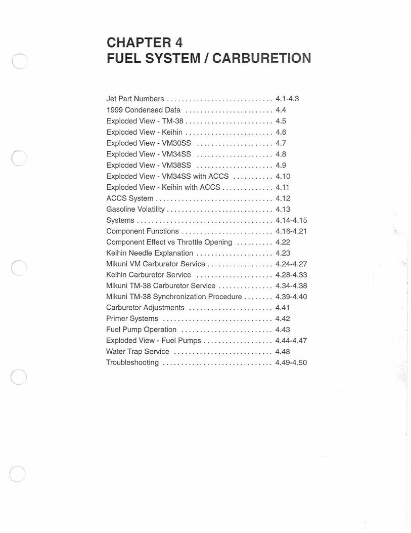
CHAPTER 4 FUEL SYSTEM I CARBURETION Jet Part Numbers ............ . .... . .. .. ....... 4.1-4.3 1999 Condensed Data . ........... . ... .. . .... . 4.4 Exploded View - TM-38 . ........ . .. . ........... 4.5 Exploded View - Keihin ....... ..... .. .. ... ... .. 4.6 Exploded View - VM30SS ..... .. ........ . ..... 4.7 c Exploded View - VM34SS .... .. . .... .. ... . .... 4.8 Exploded View - VM38SS . .. .. ....... . ....... . 4.9 Exploded View - VM34SS with ACCS ........ . .. 4.10 Exploded View - Keihin with ACCS ... .. .. ....... 4.11 ACCS System . ............................... 4.12 Gasoline Volatility ... .. .. ................... .. . 4.13 Systems .... ... .. ....... . ....... ... ....... . . . 4.14-4.15 Component Functions . . .. . .. . ...... ... ...... .. 4.16-4 .2 1 Component Effect vs Throttle Opening . ........ . 4.22 Keihin Needle Explanation . ...... ..... ........ . 4. 23 Mikuni VM Carburetor Service .. . ..... . .... . .. .. 4.24-4.27 Keihin Carburetor Service . ........... . ... . .... 4.28-4.33 c Mikuni TM-38 Carburetor Service ... .... ........ 4.34-4.38 Mikuni TM-38 Synchronization Procedure ....... . 4.39-4.40 Carburetor Adjustments ... .. ... ....... .. . ..... 4.41 Primer Systems .... .. . .. . .. ... ........ ..... .. 4.42 Fuel Pump Operation ...... . ........ . .... ... . . 4.43 Exploded View - Fuel Pumps ... ..... ...... .. ... 4.44-4.47 Water Trap Service .. . ........... ... ...... . ... 4.48 Troubleshooting .. .... ...... ... ...... ... .. ... . 4.49-4.50 ( .... __

Welcome message from author
This document is posted to help you gain knowledge. Please leave a comment to let me know what you think about it! Share it to your friends and learn new things together.
Transcript
CHAPTER 4 FUEL SYSTEM I CARBURETION
Jet Part Numbers ............ . .... . .. .. ....... 4.1-4.3
1999 Condensed Data . ........... . ... .. . .... . 4.4
Exploded View - TM-38 . ........ . .. . ........... 4.5
Exploded View - Keihin ....... . . . . . .. .. ... ... .. 4.6
Exploded View - VM30SS ..... . . ........ . ..... 4.7
c Exploded View - VM34SS . . . . .. . .... .. ... . .... 4.8
Exploded View - VM38SS . .. .. ....... . ....... . 4.9
Exploded View - VM34SS with ACCS ........ . .. 4.10
Exploded View - Keihin with ACCS ... .. . . ....... 4.11
ACCS System . ............................... 4.12
Gasoline Volatility ... .. . . ................... .. . 4.13
Systems .... ... . . ....... . ....... . . . ....... . . . 4.14-4.15
Component Functions . . .. . .. . ...... . . . ...... .. 4.16-4.21
Component Effect vs Throttle Opening . ........ . 4.22
Keihin Needle Explanation . ...... . . . . . ........ . 4.23
Mikuni VM Carburetor Service .. . ..... . .... . .. .. 4.24-4.27
Keihin Carburetor Service . ........... . ... . .... 4.28-4.33 c Mikuni TM-38 Carburetor Service ... .... ........ 4.34-4.38
Mikuni TM-38 Synchronization Procedure ....... . 4.39-4.40
Carburetor Adjustments ... . . ... ....... .. . ..... 4.41
Primer Systems .... .. . .. . .. . . . ........ ..... .. 4.42
Fuel Pump Operation ...... . ........ . .... ... . . 4.43
Exploded View - Fuel Pumps ... ..... ...... .. ... 4.44-4.47
Water Trap Service .. . ........... . . . ...... . ... 4.48
Troubleshooting .. .... ...... ... ...... . . . .. ... . 4.49-4.50
( ....__

~
_)
J
)

c
c
L
FUEL SYSTEM/CARBURETION Jet Part Numbers
Whenever servicing the carburetor or fuel system, it is important to heed the following warnings.
A WARNING
Gasoline is extremely flammable and explosive under certain conditions.
A Always stop the engine and refuel outdoors or in a well ventilated area.
A Do not smoke or allow open flames or sparks in or near the area where refueling is performed or where gasoline is stored or used.
A Do not overfill the tank. Do not fill the tank neck.
A If you get gasoline in your eyes or if you swallow gasoline, see your doctor immediately.
A If you spil l gasoline on your skin or clothing, immediately wash it off with soap and water and change clothing.
A Never start the engine or let it run in an enclosed area. Gasoline powered engine exhaust fumes are poisonous and can cause loss of consciousness and death in a short time.
Jet Part Numbers
The following chart lists main and pi lot jets and the part number of each that are presently avai lable.
Mikuni Mikuni Keihin Keihin PILOT JET NO. PART NO. 25 .. . . . ........ 3130064 30 .. . ... . . . . . . . 3130065 35 ........ . .... 3130066 40 .... . ... . .... 3130067 45 ....... ..... . 3130068 50 . . .... . . . .. . . 3130629 55 . . .... ....... 3130070
Mikuni HEX HEAD MAIN JET NO. PART NO. 80 .. .. ....... .. 3130099 85 ............. 3130100 90 ...... ....... 3130101 95 .. .. ... .. . ... 3130102 100 ... . . ... . ... 3130103 105 . . . . . ... . ... 3130104 110 .. .. . .. . .... 3130105 115 ......... .. . 3130106 120 . ... . . .. .. . . 3130107 125 ... .. . . . . ... 3130108 130 .... . ...... . 3130109 135 . . . ...... . . . 3130110 140 . . . .. . . . . . . . 3130111 145 .. . .... . . . . . 3130112 150 . . . .... ... .. 3130113 155 ..... . . . .... 3130114 160 . ..... . ..... 3130115 165 . ........... 3130116 170 ...... .... .. 3130117 175 . . .... .. . ... 3130118 180 ...... . .. . .. 3130119 185 .. .. ........ 3130120 190 . .. ....... .. 3130121 195 .. . ..... .... 3130122 200 .. . .. .. ..... 3130123 210 .. . ... . . . .. . 3130124 220 ...... ... ... 3130125 230 ......... ... 3130126 240 . ... . . .. ... . 3130127
Polaris Industries Inc.
PILOT JET NO. PART NO. PILOT JET PART NO. PILOT JET PART NO . 50 3130069 55 3130070 60 3130071 65 3130072
Mikuni HEX HEAD MAIN JET NO. PART NO. 250 ............ 3130128 260 ..... .. . . ... 3130129 270 . ... . . .. . . . . 3130130 280 . ... .. . ..... 3130131 290 ......... . .. 3130132 300 .... . . . .. . .. 3130133 310 ... . .. . . .. . . 3130134 320 ............ 3130135 330 ............ 3130136 340 .... .. . .. ... 3130137 350 ........ .. . . 3130138 360 ....... . . ... 3130139 370 .. ····· . .... 3130290 380 . ..•... . .. .. 31301 40 390 . . . .... .. ... 3130480 400 ...... . . . . . . 3130141 410 ... .... .... . 3130599 420 ... . .. .... . . 3130142 430 .... . . ...... 3130143 440 ... . .... .... 3130144 450 ..... . .. . . . . 3130145 460 .. . . .. . ..... 3130146 470 .. .......... 3130147 490 . .. . .. . . . ... 3130 148 500 . ... . ....... 3130149 530 .. . ........ . 3130150 560 ... .. .. . ... . 3130 151 590 . . . .. ..... .. 3130152 620 . .. .. .. . . ... 3130153
4 .1
35 38 40 42 45 48
3050219-35 50 . . . . . 3050219-50 .. .. . 3050219-38 52 ..... 3050219-52 .. ... 3050219-40 55 . .. . . 3050219-55 ..... 3050219-42 58 .. . . . 3050219-58 ..... 3050219-45 60 .. .. . 3050219-60 .... . 3050219-48 62 .. . . . 3050219-62
65 3050219-65
Keihin Long Hex Head MAIN JET NO PART NO. 140 .... . .... 3050235-140 142 . . . . . . . . . 3050235-142 145 . .... . . . . 3050235-145 148 . ... .. ... 3050235-148 150 . . . . . . . . . 3050235-150 152 •• • • • 0 • •• 3050235-152 155 . . . . . . . . . 3050235-155 158 . . . . . . . . . 3050235-158 160 .... .. .. . 3050235-160 162 . . . . . . . . . 3050235-162 165 ........ . 3050235-165 168 . . . . . . . . . 3050235-168 170 . . . . . . . . . 3050235-170 172 . . . . . . . . . 3050235-172 176 . . . . . . . . . 3050235-176 178 ..... .. .. 3050235-178 180 .. ... .. . . 3050235-180 182 . . ....... 3050235-182 185 • • • 0 • • • •• 3050235-185 188 ........ . 3050235-188 190 . . . . . . . . . 3050235-190 192 • • • 0 • • • • • 3050235-192 195 . . . . . . . . . 3050235-195 198 . . . . . . . . . 3050235-198 200 ... . ..... 3050235-200 205 . . . . . . . . . 3050235-205 210 . . . . . . . . . 3050235-210 215 . . . . . . . . . 3050235-215 220 . . . . . . . . . 3050235-220
10/98

FUEL SYSTEM/CARBURETION Jet Part Numbers
Jet Needle Part Numbers (Mikuni)
JET NEEDLE NO. PART NO. 5DP7 .. . ..... ... 3130155 5DT49 ...... .. .. 3130154 5DP10 ... .. . . ... 3130333 5DP10 .. .. .. .... 3130310 5DT2 . . . . . . . . . . . 3130473 5D78 ''' o ' ' ' 'I'' 3130667 5F81 .... . . . . .... 3130528 6CEY6 ... ..... .. 3130476 6CF1 . . . . . . . . . . . 3130725 6CGY3 ..... ... .. 3130484 6CGY6 .... .. .... 3130652 6DH3 . .. ..... . .. 3130470
Jet Needle Part Numbers (Keihin) JET NEEDLE NO. PART NO. R-1368G . . . . . . . . 3050244 R-1370G . . . . . . . . 3050220 R-1371 G . . . . . . . . 3050256 R-1372J .. ... .... 3050247
Needle Jet Part Numbers (Mikuni)
NEEDLE JET NO PART NO. P-4 (159) . . .. . . .. 3130162 P-2 (166) ........ 3130460 P-4 (166) . ....... 3130348 P-4 (166) . . . .. ... 3130499 P-6 (166) . ... .... 3130160 P-8 (166) . . .... . . 3130421 0 -2 (166) ... . .... 3130376 0-4 (169) ........ 3130166 0 -4 (169) ... . . ... 3130409 0-6 (169) ..... 3130358 0-6 (169) ........ 3130469 0 -8 (169) ........ 3130453 0 -8 (171) ..... . . . 3130035 P-0 (225) .. . . . .. 3130579 P-2 (255) ........ 3130608 P-2 (259) . .. . . . . . 3130161 P-0 (247) . .. . .. .. 3130671 P-2 (247) ........ 3130672 P-4 (247) .. . ..... 3130641
Throttle Valve Part Numbers (Keihin) Throttle Valve No. PART NO. 3.0 3050234-802 4.0 . . . . . . . . . . . . . 3050234-C02 5.0 . . . . . . . . . . . . . 3050234-D02 5.5 . . . . • . . . . . . . . 3050234-J02 6.0 ....... . . . . . . 3050234-E02 6.5 . . . . . . . . . . . . . 3050234-K02 7.0 . . ....... . . .. 3050234-F02 7.5 ... . . .. . . . . .. 3050234-L02 8.0 . . ... . .. . . . . . 3050234-802 9.0 . . .. .. .. . .. . . 3050234-H02
10/98
JET NEEDLE NO. PART NO. 6DH4 . ..... . . . . . . . ... 3130402 6DH5 ....... . ..... ... 3130391 6DH7 . . .. ... . ...... .. 3130329 6DH8 .. . .. .. . . . ... ... 3130645 6DH29 . .. . . ... ... ... . 3130462 6DP1 ............ . ... 3130156 6DP17 .... .. ......... 3130374 6EJ26 ... ..... .. .... . 3130423 6EJ3 ...... . .. . ... ... 3130680 6F4 .... . . .. . . . ...... 3130319 6F9 . . .. ... ..... .... . 3130378
JET NEEDLE NO. PART NO. R-1369G . . . . . . . . . . . . . 3050245 R-1370J . ....... . .... 3050221 R-1371J ....... . . . . .. 3050246
NEEDLE JET NO PART NO. P-6 (247) ... . ... .. . . .. 3130655 P-8 (247) .... . ..... . .. 3130382 0 -0 (247) . ........ . . . 3130414 0 -2 (247) . ..... .. . ... 3130165 0 -4 (247) . . ... ...... . 3130603 0-8 (247) ... ...... .. . 3130485 R-0 (247) ....... ..... 3130477 P-0 (286) . . . . . . . . . . . . . 3130607 P-2 (286) ... . . .. .. .... 3130608 0-4 (286) ... .. ..... . . 3130635 0-6 (480) . . ..... ..... 3130429 0-8 (480) ....... .. ... 3130683 P-2 (480) ..... . . .. .... 3130675 P-4(480) . ...... .. .... 3130639 0-6 (480) .. . .. ... .. . . 3130618 P-8 (513) .. . .. . . .. ... 3130510
)
4.2 Polaris Industries Inc.

c
c
DESCRIPTION
Jet Needles
Jet Needle J8-9FH04-57
Jet Needle J8-9EH01-57
Jet Needle J8-9DH01-54
Jet Needle J8-9CJB01-50
Needle Jets
Needle Jet 0-8
Needle Jet P-0
Needle Jet P-2
Needle Jet P-4
Needle Jet P-6
Needle Jet P-8
Need le Jet Q-0
Starter Jets
Starter Jet 130
Starter Jet 135
Starter Jet 140
Starter Jet 145
Starter Jet 150
Starter Jet 155
Starter Jet 160
Pilot Air Jets
Pilot Air Jet 0.5
Pilot Air Jet 0.6
Pilot Air Jet 0.7
Pilot Air Jet 0.8
Pilot Air Jet 0.9
Pilot Air Jet 1.0
Pilot Air Jet 1.1
Pilot Air Jet 1.2
PART NUMBER
3130794
3130795
3130796
3130797
3130798
3130799
3130800
3130801
3130802
3130803
3130804
3130805
3130767
3130768
3130769
3130770
3130771
3130772
3130773
3130774
3130775
3130776
3130777
3130778
3130779
3130780
FUEL SYSTEM/CARBURETION Mikuni TM-38 Jet Part Numbers
DESCRIPTION PART NUMBER
Pilot Air Jets Cont.
Pilot Air Jet 1.3 3130781
Pilot Air Jet 1.4 3130782
Pilot Air Jet 1.5 3130783
Pilot Air Jet 1.6 3130784
Pilot Air Jet 1.7 3130785
Pilot Air Jet 1.8 3130786
Pilot Air Jet 1.9 3130787
Pilot Air Jet 2.0 3130788
Piston Valves (Slides)
Piston Valve 1.5 3130940
Piston Valve 2.0 3130789
Piston Valve 2.5 3130790
Piston Valve 3.0 3130791
Piston Valve 3.5 3130792
Piston Valve 4.0 3130793
The part numbers for main jets and pilot jets are the same as Mikuni VM round slide carburetors.
Polaris Industries Inc. 4.3 10/98
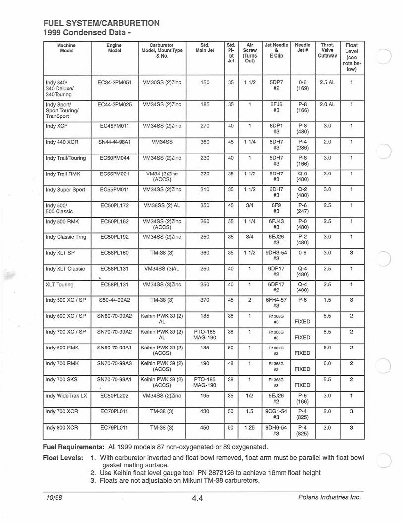
FUEL SYSTEM/CARBURETION 1999 Condensed Data -
Machine Engine Carburetor Model Model Model, Mount Type
&No.
Indy 340/ EC34-2PM051 VM30SS (2)Zinc 340 Deluxe/ 340Touring
Indy Sport! EC44-3PM025 VM34SS (2)Zinc Sport Touring/ TranSport
Indy XCF EC45PM011 VM34SS (2)Zinc
lndy440 XCR SN44-44-98A 1 VM34SS
Indy Trai l/Touring EC50PM044 VM34SS (2)Zinc
Indy Trail RMK EC55PM021 VM34 (2)Zinc (ACCS)
Indy Super Sport EC55PM011 VM34SS (2)Zinc
Indy 500/ EC50PL 172 VM38SS (2) AL 500 Classic
lndy500 RMK EC50PL 162 VM34SS (2)Zinc (ACCS)
Indy Classic Trng EC50PL192 VM34SS (2)Zinc
Indy XLT SP EC58PL160 TM-38 (3)
Indy XLT Classic EC58PL131 VM34SS (3)AL . XLT Touring EC58PL131 VM34SS (3)Zinc
Indy 500 XC I SP S50-44-99A2 TM-38 (3)
Indy 600 XC I SP SN60-70-99A2 Keihin PWK 39 (2) AL
Indy 700 XC I SP SN70-70-99A2 Keihin PWK 39 (2) AL
Indy 600 RMK SN60-70-99A 1 Keihin PWK 39 (2) (ACCS)
lndy700 RMK SN70-70-99A3 Keihin PWK 39 (2) (ACCS)
Indy 700 SKS SN70-70-99A 1 Keihin PWK 39 (2) (ACCS)
Indy WideTrak LX EC50PL202 VM34SS (2)Zinc
Indy 700 XCR EC70PL011 TM-38 (3)
Indy BOO XCR EC79PL011 TM-38 (3)
Std. Std. Air Jet Needle Main Jet Pi- Screw &
lot (Turns ECiip Jet Out)
150 35 1 1/2 5DP7 #2
185 35 1 6FJ6 #3
270 40 1 6DP1 #3
360 45 1 1/4 6DH7 #3
230 40 1 6DH7 #3
270 35 1 1/2 6DH7 #3
310 35 1 1/2 6DH7 #3
350 45 3/4 6F9 #3
260 55 1 1/4 6FJ43 #3
250 35 3/4 6EJ26 #3
360 35 1 1/2 9DH3-54 #3
250 40 1 6DP17 #2
250 40 1 6DP17 #2
370 45 2 6FH4-57 #3
185 38 1 R1368G
#3
PT0-185 38 1 R1368G
MAG-190 #3
185 50 1 R1367G
#2
190 48 1 R1368G
#2
PT0-185 38 1 R1368G
MAG-190 #3
195 35 1/2 6EJ26 #2
430 50 1.5 9CG1-54 #3
450 50 1.25 9DH6-54 #3
Fuel Requirements: All 1999 models 87 non-oxygenated or 89 oxygenated.
Needle Throt. Float Jet# Va lve Level
Cutaway (see note be-
low)
0-6 2.5AL 1 (169)
P-8 2.0AL 1 (166)
P-8 3.0 1 (480)
P-4 2.0 1 (286)
P-8 3.0 1 (1 66)
Q-0 3.0 1 (480)
Q-2 3.0 1 (480)
P-6 2.5 1 (247)
P-0 2.5 1 (480)
P-2 3.0 1 (480)
0-6 3.0 3
Q-4 2.5 1 (480)
Q-4 2.5 1 (480)
P-6 1.5 3
5.5 2 FIXED
5.5 2 FIXED
6.0 2 FIXED
6.0 2 FIXED
5.5 2 FIXED
P-6 3.0 1 (166)
P-4 2.0 3 (825)
P-4 2.0 3 (825)
Float Levels: 1. With carburetor inverted and float bowl removed, float arm must be parallel with float bowl gasket mating surface.
2. Use Keihin float level gauge tool PN 2872126 to achieve 16mm float height 3. Floats are not adjustable on Mikuni TM-38 carburetors.
10/98 4.4 Polaris Industries Inc.
)
)
-

c
c
1 1 Top Cap
Gasket
• , .---- Adjustment Screw
'f ~ R. i 4 1- mg /
V'" ........._Lever
a @ ~ d (!) 0 ~ Plate Plate /
(!) ~~ (!) d //Packing /F,unnel Cap \. ~@ a...-- E-Ring /'
~ . Rmg Spring -
®- Guide~ / / Holder Piston Valve - /
~- Spring Jet Needle, / ~
FUEL SYSTEM/CARBURETION Exploded View -Mikuni TM - 38
CheGk Valve
~Cap ~Adjuster
@ @17Umr. / ~@~
Spring . g--- Pilot Jet
Main Jet-~ Starter Jet
\ _/ Plunger ! / /-......____Pilot Air Jet
~~' / Float/N~:dle & o / Seat Asm.
~ v
Drain Plug -----Q
Polaris Industries Inc. 4.5
I ~
Float Body
10/98

FUEL SYSTEM/CARBURETION Exploded View - Keihin
Adjuster
ft~ W/ Lock Nut Gasket~ -~~
Spring ~
~ ~ ~ Spring Seat G1 / ~ /Retainer
Jet Needle V "E" Clip
'~
/Vent
1 ~ ~- ,/e ~-/ ,~/
j/( Idle Adjustment /, , '
serene ~~~ ~ I,
~-1 Main Jet
~. . g e-;}-- Fuel Inlet Needle
Air Screw ~ 8 Float Pi lot Jet
0-Ring
10/98 4.6 Polaris Industries Inc.
)
)
r
(
c
(
Polaris Industries Inc. 4 .7
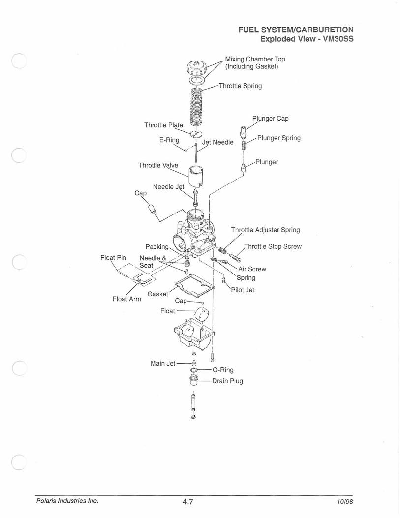
FUEL SYSTEM/CARBURETION Exploded View - VM30SS
Mixing Chamber Top (Including Gasket)
Throttle Spring
10/98
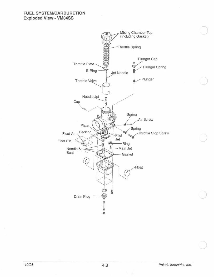
FUEL SYSTEM/CARBURETION Exploded View - VM34SS
Drain Plug
10/98
~ Mixing Chamber Top ~/ (Including Gasket)
CD
4.8
--Throttle Spring
Plunger Cap
V Plunger Spring
J t Needle ~ VPiunger
I
) ( /
Polaris Industries Inc.
n
c Polaris Industries Inc.
Plat
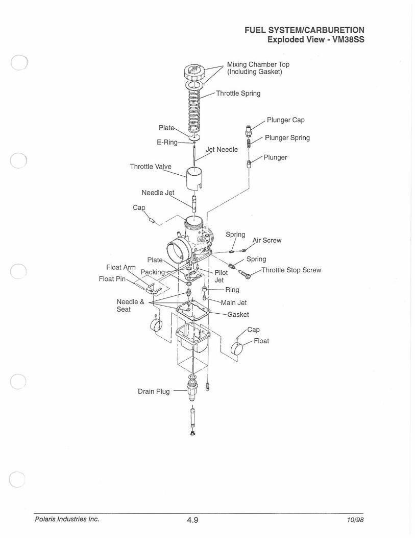
FUEL SYSTEM/CARBURETION Exploded View - VM38SS
Plunger Cap
~Plunger Spring
Jet Needle VI
rPiunger
) (/
Spring j Air Screw
~"'--<-- .......... - -~ Plate
Fl:~::~:~~g . ~~~>
Needle & ~---,---,&li'l
Seat Gasket
Drain Plug -~ ~
4.9 10/98
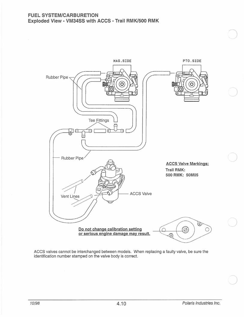
FUEL SYSTEM/CARBURETION Exploded View- VM34SS with ACCS- Trail RMK/500 RMK
MAG . SIDE PTO.SIDE
Rubber Pipe
Rubber Pipe/ ACCS Valve Markings:
Trail RMK: 500 RMK: 50M05
ACCS Valve
Do not change calibration setting or serious engine damage may result.
ACCS valves cannot be interchanged between models. When replacing a faulty valve, be sure the identification number stamped on the valve body is correct.
10/98 4.10 Polaris Industries Inc.

r
FUEL SYSTEM/CARBURETION Exploded View- Keihin Carbs with ACCS - 600 RMK/700 RMK
ACCS Valve
~ I
Do not change calibration setting or serious engine damage may result.
ACCS Valve
ACCS Valve Markings :
600 RMK: 1253232 700 RMK: 1251086
ACCS valves cannot be interchanged between models. When replacing a faulty valve, be sure the identification number stamped on the valve body is correct.
Polaris Industries Inc. 4. 11 10/98
FUEL SYSTEM/CARBURETION ACCS System
Altitude Compensating Carburetor System (ACCS)
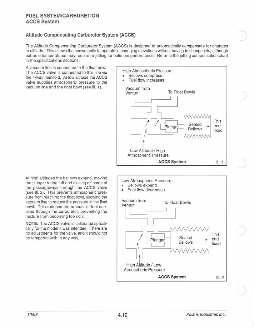
The Altitude Compensating Carburetor System (ACCS) is designed to automatically compensate for changes in altitude. This allows the snowmobile to operate in changing elevations without having to change jets, although extreme temperatures may require re-jetting for optimum performance. Refer to the jetting compensation chart in the specifications sections.
A vacuum line is connected to the float bowl. The ACCS valve is connected to this line via the 4-way manifold. At low altitude the ACCS valve supplies atmospheric pressure to the vacuum line and the float bowl (see Ill. 1 ).
At high altitudes the bellows expand, moving the plunger to the left and closing off some of the passageways through the ACCS valve (see Ill. 2). This prevents atmospheric pressure from reaching the float bowl, allowing the vacuum line to reduce the pressure in the float bowl. This reduces the amount of fuel supplied through the carburetor, preventing the mixture from becoming too rich.
NOTE: The ACCS valve is calibrated specifically for the model it was intended. There are no adjustments for the valve, and it should not be tampered '!Vith in any way.
10/98
High Atmospheric Pressure-• Bellows compress • Fuel flow increases
Vacuum from Venturi To Float Bowls
Low Altitude I High Atmospheric Pressure
ACCS System
Low Atmospheric Pressure-• Bellows expand • Fuel flow decreases
To Float Bowls
This end fixed
Ill. 1
This end fixed
Ill. 2
4.12 Polaris Industries Inc.

c
(
(
Explanation of Gasoline Volatility
FUEL SYSTEM/CARBURETION Gasoline Volatility
One of the sometimes misunderstood properties of gasoline is its volatility, or ability to vaporize at different ambient temperatures and altitudes during the year.
When gasoline is blended, it is given a Reid Vapor Pressure (RVP) number which reflects its ability to vaporize or mix with air at a given temperature range. Gasoline vapor pressure is measured by putting a sample of fuel inside a closed container and applying a specified amount of heat to the container for a certain amount of time. RVP will vary from about 7.0 PSI during the summer to approximately 13.5 PSI during the colder months. Service stations selling a large volume of fuel will normally have the correct blend to work well at all times throughout the year in their local area.
When the weather is very cold, gasoline must be able to vaporize very quickly in order for an engine to start and warm up properly. If summer blend fuel is being used in the winter, little or no vaporization will occur. Droplets will form causing flooding and very hard starting .
If winter blend fuel is being used during the summer months, it may cause vapor lock (boiling fuel) inside the fuel lines, fuel pump, or carburetor. This will cause warm engine driveability problems and hard starting when warm. Some states are limiting the Reid Vapor number to 9.0 PSI year around to help meet evaporative emissions standards.
Warm Weather Low Vaporization Rate
Maximum Reid Vapor Ambient Air Temp. Range
Class Pressure Low High
A 7.0 PSI 60° F 110° F +
B 9.0 PSI 50° F 110° F
c 10.5 PSI 40° F 9 ]0 F
D 12.0 PSI 30° F 85° F
E 13.5 PSI 20° F 69° F
Cold Weather Add 2.4° F for each 1000 feet above seal level. High Vaporization Rate
Polaris Industries Inc. 4.13 10/98
/

FUEL SYSTEM/CARBURETION Systems
Float Chamber Venting
Fuel fl ows through a carburetor by creating a pressure difference between the venturi and the float bowl. The greater the pressure difference, the greater the fuel flow. On some models the float bowl is vented to the handlebars. This provides consistent atmospheric pressure for a consistent fuel flow. If the vent lines become kinked, plugged, or exposed to fluctuating pressures (under hood) the pressure difference will change, causing erratic fuel flow.
Polaris has airbox venting on some models. The vent lines are connected to a baffle inside the airbox. This provides a more consistent pressure difference between the carburetor venturi and the float bowl as the vacuum inside the airbox changes. For example, if the airbox foam filter becomes restricted with snow when riding in powder, the airbox vacuum increases. Without airbox venting, the pressure difference wou ld increase substantial ly, choking or flooding the engine. With airbox venting, the pressure difference remains the same, creating a slightlyleaner mixture to compensate for reduced air flow.
10/98
Vent Line Routing (Oppos ite Carb to Handlebar)
Tee Fitting
One Way
Drain Hose ___ ,, 61i~:ction
\--=tt---tt-- Atmospheric Pressure Check Valve -. j
Through Valve Some Models Have
Interconnecting Lines Between each Carb
r •1 ____:_.t...•
'\.. Baffle Tube -- - - -
Air Box
_j
Tee Fittings Are -V Orientated Vertically
I -1
Some models have airbox venting
1~ ~
4.14 Polaris Industries Inc.

(
FUEL SYSTEM/CARBURETION Fuel Delivery System - Typical
The fuel system contains many components which directly affect fuel mixture and driveability. When performing diagnosis or carburetor maintenance, the entire fuel delivery system should be inspected. The illustration below shows parts of the system requiring periodic maintenance to ensure there is no fuel or air leaks present.
Fuel filters should be replaced at least once per season or more often if any contamination is suspected.
Fuel lines should be replaced every other season or more often if they become brittle or swollen . Fittings shou ld be inspected at that time for cracks or leaks.
Test run and check the fuel system for leaks any time parts are replaced. Verify that all lines are routed correctly away from any moving parts.
Weighted Pickup and Line Seal
Vent Lines I Carb Mounts
Impulse Fitting at Crankcase
NOTE: 1999 500 XC and 500 XC SP fuel filters are inside the fuel tank. To inspect/replace filter:
• Remove fuel from tank
• Remove air box
Remove fuel line fitting from fuel tank
• Pull fuel line, pickup, and filter from tank
Polaris Industries Inc. 4.15 10/98

FUEL SYSTEM/CARBURETION Typical Mikuni Starter System- Closed Throttle
Mikuni carburetors use a starter enricher system rather than a choke. In this type of carburetor, fuel and air for starting the engine are metered with entirely independent jets. The fuel metered in the starter jet is mixed with ) air and is broken into tiny particles in the emulsion tube. The mixture then flows into the plunger area, mixes again with air coming from the air intake port for starting and is delivered to the engine through the fuel discharge nozzle in the optimum air/fuel ratio. The starter is opened and closed by means of the starter plunger. The starter type carburetor is constructed to utilize the negative pressure of the inlet pipe, so it is important that the throttle valve is closed when starting the engine.
10/98
1--;--=--=-_-_-1 I I I I I I I I I I I I I I I
~ I I I : I I I ,_
Cable Adjuster
Cable Adjuster Lock Nut
Plunger Spring
Plunger Cap , Throttle Valve Starter Plunger
Inlet Bleed Air
4.16 Polaris Industries Inc.

c
FUEL SYSTEM/CARBURETION Pilot System (0-3/8 Throttle)
The pilot system's main function is to meter fuel at idle and low speed driving. Though its main function is to supply fuel at low speed, it does feed fuel continuously throughout the enti re operating range.
Fuel for the pilot jet is drawn from the float bowl, mixed with air regulated by the air screw, and delivered to the engine through the pilot outlet.
The mixture is regulated to some degree by adjusting the air screw. When the air screw is closed, the fuel mixture is made richer as the amount of air is reduced. When the ai r screw is opened, the mixture is made more lean as the amount of air is increased.
Pilot Jet
From idling to low speeds, the fuel supply is metered by the pilot jet. There are several air bleed openings in the sides of the pilot jet which reduce the fuel to mist. The number stamped on the jet is an indication of the amount of fuel in cc's which passes through the jet during a one minute interval under a given set of conditions.
Pilot Air Screw
The pilot air screw contro ls the fuel mixture from idle to low speeds. The tapered tip of the air screw projects into the air passage leading to the pilot jet air bleeds. By turning the screw in or out, the cross sectional area of the air passage is varied, in turn varying the pilot jet air supply and chang ing the mixture ratio.
Polaris Industries Inc. 4.17
Throttle Valve
Indicator Number
Pilot Air Screw
~ /
10/98
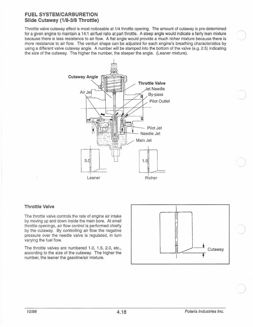
FUEL SYSTEM/CARBURETION Slide Cutaway (1/8-3/8 Throttle)
Throttle valve cutaway effect is most noticeable at 1/4 throttle opening. The amount of cutaway is pre-determined for a given engine to maintain a 14:1 air/fuel ratio at part throttle . A steep angle would indicate a fairly lean mixture because there is less resistance to air flow. A flat angle would provide a much richer mixture because there is more resistance to air flow. The venturi shape can be adjusted tor each engine's breathing characteristics by using a different valve cutaway angle. A number will be stamped into the bottom of the valve (e.g. 2.5) indicating the size of the cutaway. The higher the number, the steeper the angle. (Leaner mixture) .
Cutaway Angle
Throttle Valve
By-pass
Pilot Outlet
Pilot Jet 1!11="'11tt--....::..__ Needle Jet
3.
Leaner
Throttle Valve
The throttle valve controls the rate of engine air intake by moving up and down inside the main bore. At small throttle openings, air flow control is performed chiefly by the cutaway. By controlling air flow the negative pressure over the needle valve is regulated, in turn varying the fuel flow.
The throttle valves are numbered 1.0, 1.5, 2.0, etc., according to the size of the cutaway. The higher the number, the leaner the gasoline/air mixture.
10/98 4.18
Main Jet
Richer
I
I ~___! Cutaway
'
Polaris Industries Inc.
r
r
c
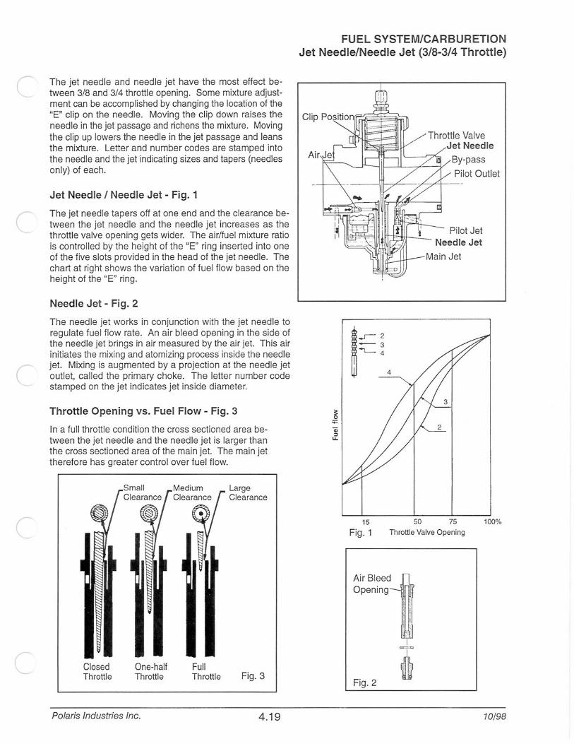
The jet needle and needle jet have the most effect between 3/8 and 3/4 throttle opening. Some mixture adjustment can be accomplished by changing the location of the "E" clip on the needle. Moving the clip down raises the needle in the jet passage and richens the mixture. Moving the clip up lowers the needle in the jet passage and leans the mixture. Letter and number codes are stamped into the needle and the jet indicating sizes and tapers (needles only) of each.
Jet Needle I Needle Jet - Fig. 1
The jet needle tapers off at one end and the clearance between the jet needle and the needle jet increases as the throttle valve opening gets wider. The air/fuel mixture ratio is controlled by the height of the "E" ring inserted into one of the five slots provided in the head of the jet needle. The chart at right shows the variation of fuel flow based on the height of the "E" ring .
Needle Jet - Fig. 2
The needle jet works in conjunction with the jet needle to regulate fuel flow rate. An air bleed opening in the side of the needle jet brings in air measured by the air jet. This air initiates the mixing and atomizing process inside the needle jet. Mixing is augmented by a projection at the needle jet outlet, called the primary choke. The letter number code stamped on the jet indicates jet inside diameter.
Throttle Opening vs. Fuel Flow - Fig. 3
In a full throttle condition the cross sectioned area between the jet needle and the needle jet is larger than the cross sectioned area of the main jet. The main jet therefore has greater control over fuel flow.
Closed Throttle
One-half Throttle
Polaris Industries Inc.
Full Throttle
Large Clearance
Fig. 3
4.19
FUEL SYSTEM/CARBURETION Jet Needle/Needle Jet (3/8-3/4 Throttle)
;: 0
;;::
-3 ~4 ~_r- 2
4
Throttle Valve Jet Needle
By-pass
Pilot Outlet
Pilot Jet
50 75 100% 15
Fig. 1 Throttle Valve Opening
Air Bleed Opening
Fig. 2
I
fi 10/98

FUEL SYSTEM/CARBURETION Main System (3/4 to Full Throttle)
The main system is designed to deliver fuel between low speed and high speed operation. This system is made up of the jet needle, needle jet, and main jet. The main system begins to take effect as soon as there is enough air flow into the carburetor venturi to draw fuel up through the main jet and needle jet assembly. This system works in conjunction with the needle jet system.
During low speed driving, there is very little clearance between the jet needle and the needle jet; therefore, very little fuel from the main jet can pass between the jet needle and the needle jet. As the throttle valve opening is increased, the tapered jet needle is raised farther out of the needle jet, allowing greater fuel flow. Under full throttle opening, the cross sectioned area of clearance between the jet needle and the needle jet becomes greater than the cross sectioned area of the main jet. Thus the main jet is now controlling the amount of fuel flow.
Main Jet
When the throttle opening becomes greater and the area between the needle jet and jet needle increases, fuel flow is metered by the main jet. The number on the jet indicates the amount of fuel CCs which will pass through it in one minute under controlled conditions. Larger numbers give a greater flow, resulting in a richer mixture.
Main jets are screwed directly into the needle jet base.
Keihin Main Jet The number on the Keihin main jet corresponds to the diameter of the metering orifice.
Jetting Guidelines
Throttle Valve et Needle
By-pass
Pilot Outle
Changes in altitude and temperature affect air density, which is essentially the amount of oxygen available for combustion. In low elevations and cold temperatures, the air has more oxygen. In higher elevations and higher temperatures, the air is less dense.
)
Carburetors on most Polaris models are calibrated for an altitude of 0-3000 ft (0-900 meters) and ambient temper- ) atures between -20° to +10° F (-29° to -12° C). All carburetors must be re-calibrated if operated outside the pro-duction temperature and/or altitude range. The main jet installed in production is not correct for all altitudes and/or temperatures.
1· CAUTION: :1
A main jet that is too small will cause a lean operating condition and may cause serious engine damage. Jet the carburetors carefully for elevation and temperature according to the jetting charts in this manual, or the jetting charts in the Owner's Safety and Maintenance Manual for each particular model.
NOTE: It is the owner's responsibility to ensure that the correct jets are installed in the machine for a geographical area. Be very careful when jetting down in warm weather. As the weather turns colder it will be necessary to re-jet upward to prevent engine damage. When selecting the proper main jet always use the lowest elevation and temperature that is likely to be encountered.
10/98 4.20 Polaris Industries Inc.
(
(
(_
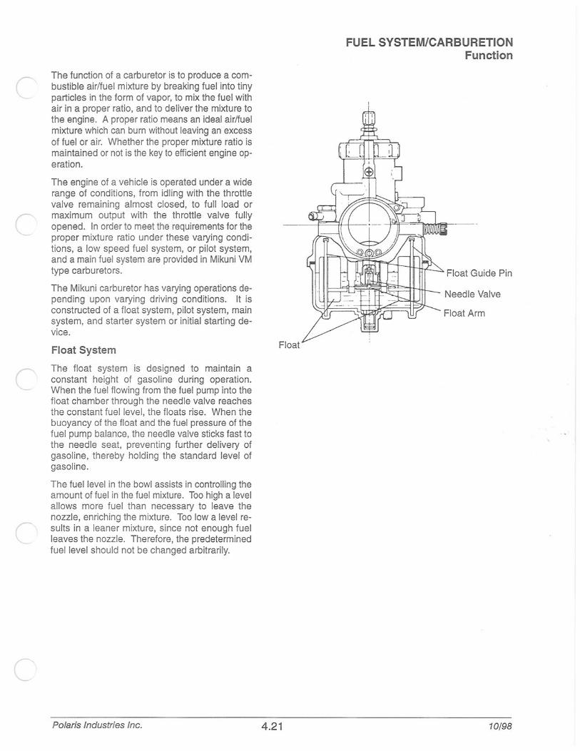
The function of a carburetor is to produce a combustible air/fuel mixture by breaking fuel into tiny particles in the form of vapor, to mix the fuel with air in a proper ratio, and to deliver the mixture to the engine. A proper ratio means an ideal air/fuel mixture which can burn without leaving an excess of fuel or air. Whether the proper mixture ratio is maintained or not is the key to efficient engine operation.
The engine of a vehicle is operated under a wide range of conditions, from idling with the throttle valve remaining almost closed, to full load or maximum output with the throttle valve fully opened. In order to meet the requirements for the proper mixture ratio under these varying conditions, a low speed fuel system, or pilot system, and a main fuel system are provided in Mikuni VM type carburetors.
The Mikuni carburetor has varying operations depending upon varying driving cond itions. It is constructed of a float system, pilot system, main system, and starter system or in itial starting device.
Float System
The float system is designed to maintain a constant height of gasoline during operation. When the fuel flowing from the fuel pump into the float chamber through the needle valve reaches the constant fuel level, the floats rise. When the buoyancy of the float and the fuel pressure of the fuel pump balance, the needle valve sticks fast to the needle seat, preventing further delivery of gasoline, thereby holding the standard level of gasoline.
The fuel level in the bowl assists in controlling the amount of fuel in the fuel mixture. Too high a level allows more fuel than necessary to leave the nozzle, enriching the mixture. Too low a level results in a leaner mixture, since not enough fuel leaves the nozzle. Therefore, the predetermined fuel level should not be changed arbitrarily.
Polaris Industries Inc.
Float
4.21
FUEL SYSTEM/CARBURETION Function
Float Guide Pin
10/98
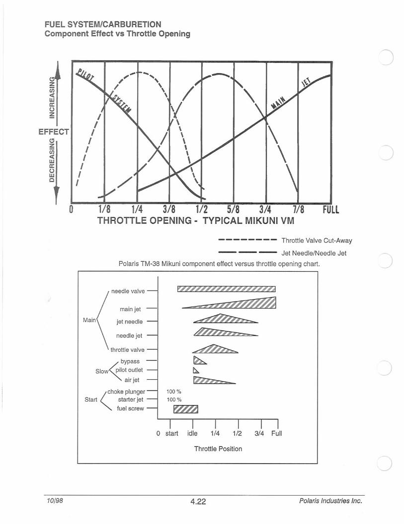
FUEL SYSTEM/CARBURETION Component Effect vs Throttle Opening
C!J z c;; <( w a: 0 z
EFFECT C!J z U'J <( w a: 0 w 0
10/98
0
I I
I I
I I
I I I
Main
1/8 1/4 3/8 1/2 5/8 3/4 7/8 FUll THROTTLE OPENING - TYPICAL MIKUNI VM
-------- Throttle Valve Cut-Away
--- Jet Needle/Needle Jet
Polari s TM-38 Mikuni component effect versus throttle opening chart.
needle valve
jet needle
needle jet
throttle valve
~ ~
~ ~ ~
~
(hoke plunger
Start starter jet 100%
100%
fuel screw
0 start idle 1/4 1/2 3/4 Fu ll
Throttle Position
4.22 Polaris Industries Inc.

FUEL SYSTEM/CARBURETION Keihin Needle Explanation
Polaris currently uses Keihin PWK 39 carburetors on some of the domestic engines. What follows is an explanation of Keihin jet needle nomenclature.
NOTE: Polaris carburetors are calibrated correctly for their intended use. It is not necessary to change needles for normal applications. The following is intended to be used as information to better understand the operation of Keihin carburetors and does not suggest that a technician should be changing jet needles for any reason. The only change for the needle that Polaris normally recommends is to the "clip" position.
Use illustrations below and the explanation to determine the affect and characteristics of different jet needles. Keihin needles generally affect fuel delivery in three areas:
1. The diameter (D) of the needle primarily controls fuel delivery from 1/8 to 1/4 throttle openings. A needle with a smaller diameter at "D" would be richer than a needle with a larger diameter at "D" in the 1/8 to 1/4 throttle range.
2. The length (L 1) of the needle mainly affects fuel delivery from 1/4 to 1/2 throttle openings. A shorter needle will be richer and a longer needle will be leaner. This produces same effect as raising or lowering the needle clip, but to a larger degree.
3. The taper (A) primordially controls fuel delivery from 1/2 to 3/4 throttle openings. A steeper taper will deliver more fuel in this throttle position range .
Taper "A" R-1370G
EXAMPLE: R-1370G
L 1 and Clip Position R-137Qg_
Diameter @ "D"
Ill. 1
Polaris Industries Inc.
0 1/8 1/4 1/2 3/4 Full
Throttle Opening
R = Aluminum Construction
13 =Taper Angle of the needle (depicted at point "A")
13= 1 °34' a 14 would be 1 °45'
The larger the number= the steeper the taper.
A steeper taper is richer than a shallow taper.
An R-1470G needle would be richer in the 1/2 to 3/4
throttle range than a R- 1370G needle.
70 = Diameter of the straight portion of the needle (see
point "0").
A larger diameter needle at point "0" would be
leaner in the 1/8 to 1/4 throttle range than a needle with a smaller diameter at point "0".
A R-1368G has a diameter of 2.685mm at point "D"
A R-1370G has a diameter of 2. 705mm at point "D"
G = The length from the top of the needle to a point on the
taper that is 2.515mm in diameter.
A "G" is shorter than a "J".
This length mainly affects mixture in the 1/4 to 1/2
throttle range.
A R- 1370G is shorter at "L 1" than a R-1370J and
a R-1370G is richer in the 1/4 to 1/2 throttle range
than a R-1370J.
4.23
2.515mm
10/98

FUEL SYSTEM/CARBURETION Mikuni VM Carburetor Service
Wear eye protection when using compressed air or cleaning solvents. Review all fuel system warnings found on page 4.1 before proceeding.
Carburetor Removal, Disassembly, and Inspection (Typical VM Mikuni)
1. Remove carburetor from engine. Before disassembling, clean outside of carburetor thoroughly with solvent.
CAUTION: I Do not use compressed air to dry at this time. The float chamber could become pressurized resulting in damage to the floats or inlet needle and seat..
2. Remove slide valve. Inspect for nicks or burrs which may cause sticking.
3. Remove jet needle by compressing return spring toward top cap and removing throttle plate which rests on top of needle "E" cl ip. Note the "E" clip position and inspect needle taper for wear. An indication of wear would be an hourglass shape or polished spots somewhere along the taper.
4. Remove enricher (choke) plunger. Check condition of seal on tip of plunger. Any nicks or cuts will cause leakage and a rich fuel condition, usually most evident at idle and low speeds. Inspect the plunger seat for damage or foreign material.
5. Check choke cable movement. Plungers and springs should move back and forth freely, without binding.
10/98 4.24
Cap--Q
Gasket--cs:;~~j) .
Spring . --- / Retainer Plate
"E" Clip-- QJ1 Jet Needle ~·/
Slide Valve ---e
Plunger Seat
Polaris Industries Inc.
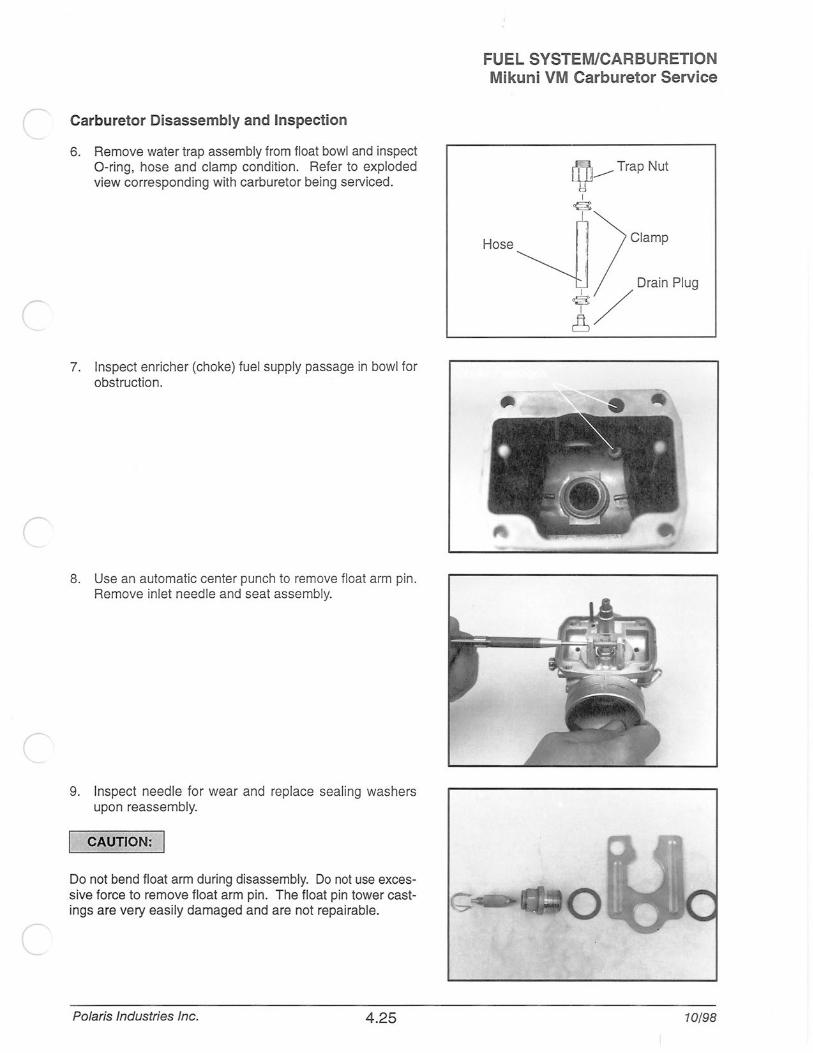
l Carburetor Disassembly and Inspection
6. Remove water trap assembly from float bowl and inspect 0-ring, hose and clamp condition. Refer to exploded view corresponding with carburetor being serviced.
7. Inspect enricher (choke) fuel supply passage in bowl for obstruction.
8. Use an automatic center punch to remove float arm pin. Remove inlet needle and seat assembly.
9. Inspect needle for wear and replace seal ing washers upon reassembly.
CAUTION: .I
Do not bend float arm during disassembly. Do not use excessive force to remove float arm pin. The float pin tower castings are very easily damaged and are not repairable.
Polaris Industries Inc. 4 .25
FUEL SYSTEM/CARBURETION Mikuni VM Carburetor Service
~---Trap Nut
I <3
I
Clamp Hose~l I .
Dra1n Plug
]:/
10/98

FUEL SYSTEM/CARBURETION Mikuni VM Carburetor Service
10. Remove main jet and washer (or spacer ring) and push needle jet into the slide valve chamber to remove. Clean air bleed hole in need le jet.
11. Remove pilot jet.
CAUTION: I
Wear eye protection when using compressed air or cleaning solvents. Review all fuel system warnings found on page 4.1 before proceeding.
12. Remove pilot air screw and clean all passages in the carburetor body with carburetor cleaner. Dry all passages and jets with compressed air. Replace gaskets and any parts which show wear or damage.
13. Reassemble carburetor, adjusting float level before installing float bowl.
Refer to page 4.27 for float level adjustment and leak testing procedures.
10/98 4.26 Polaris Industries Inc.

r
c
Float Level Adjustment
1. Remove float bowl.
2. With carburetor in an inverted position, float arm (A) should be parallel with body (B). See illustration at right. Arms must be parallel to each other.
3. To adjust float arm, bend tang contacting inlet needle.
CAUTION: I
Never bend the float arm itself.
Leak Testing Needle and Seat
1. Be sure float level is adjusted properly.
2. Invert carburetor.
3. Install float chamber and connect pressure tester PN 2870975 to fuel inlet fitting .
Pressure Tester PN 2870975
4. Apply approximately 5 PSI pressure and wait for one minute. The needle and seat should hold pressure indefinitely. If the pressure drops rapid ly replace the needle and seat assembly and/or sealing washers.
Polaris Industries Inc. 4.27
FUEL SYSTEM/CARBURETION Mikuni VM Carburetor Adjustments
10/98

FUEL SYSTEM/CARBURETION Keihin Carburetor Service
Wear eye protection when using compressed air or cleaning solvents. Review all fuel system warnings found on page 4.1 before proceeding.
Carburetor Removal, Disassembly, and Inspection
1. Remove carburetor from engine. Before disassembling, clean outside of carburetor thoroughly with solvent.
CAUTION: I Do not use compressed air to dry at this time. The float chamber could become pressurized resulting in damage to the floats or inlet needle and seat. Do not soak Keihin carburetors in carb cleaner. Clean only with aerosol cleaner.
2. Remove slide valve. Inspect for nicks or burrs which may cause sticking.
3. Remove jet needle by compressing return spring toward top cap and removing throttle cable. Disconnect cable holder and remove jet needle. Note "E" clip position and inspect needle taper for wear. An indication of wear would be an hourglass shape or polished spots somewhere along the taper.
4. Remove enricher (choke) plunger. Check condition of seal on tip of plunger. Any nicks or cuts will cause leakage and a rich fue l condition, usually most evident at idle and low speeds. Inspect the plunger seat for damage or foreign material.
5. Check enricher (choke) cable movement. Plungers and springs should move back and forth freely, without binding.
10/98 4.28
Spring~~
~~
Plunger Seat
Polaris Industries Inc.

Disassembly Cont.
6. Remove water trap assembly from float bowl and inspect 0-ring, hose and clamp condition. Refer to exploded view corresponding with carburetor being serviced.
7. Inspect choke fuel supply passage as shown for obstruction.
8. Remove float arm pin. Remove inlet needle. NOTE: Seat assembly is not replaceable. DO NOT remove .
9. Inspect needle for wear.
CAUTION: I Do not bend float arm during disassembly. Do not use excessive force to remove float arm pin. The float pin tower cast· ings are very easily damaged and are not repairable.
Polaris Industries Inc. 4.29
FUEL SYSTEM/CARBURETION Keihin Carburetor Service
LVJ__...-- Trap Nut
I ~
I
Hose..._ n Clamp
~ DrainPiug
I /
10/98

FUEL SYSTEM/CARBURETION Keihin Carburetor Service
Carburetor Disassembly Cont.
10. Remove main jet.
11 . Remove pilot jet.
12. Remove pilot air screw and clean all passages in the carburetor body with carburetor cleaner. Dry all passages and jets with compressed air. Replace gaskets and any parts which show wear or damage.
10/98 4.30
)
)
Polaris Industries Inc.

c
(
(
Carburetor Assembly
1. Install pilot jet and main jet.
2. Install inlet needle and float assembly.
3. Hold carburetor at angle shown so needle spring is not compressed. Measure from gasket surface of carb body to highest point on float. Measurement should be within specification.
Float Height- Keihin:16mm ± 2 mm
Float Level Guage: PN 2872126
4. To adjust float level, bend tang contacting inlet needle. See photo above.
CAUTION: I
Do not bend float arm. Adjustment should be made with tang contacting inlet needle.
Polaris Industries Inc. 4 .31
FUEL SYSTEM/CARBURETION Keihin Carburetor Service
Adjust float with tange o'i'lly
10/98
FUEL SYSTEM/CARBURETION Keihin Carburetor Service
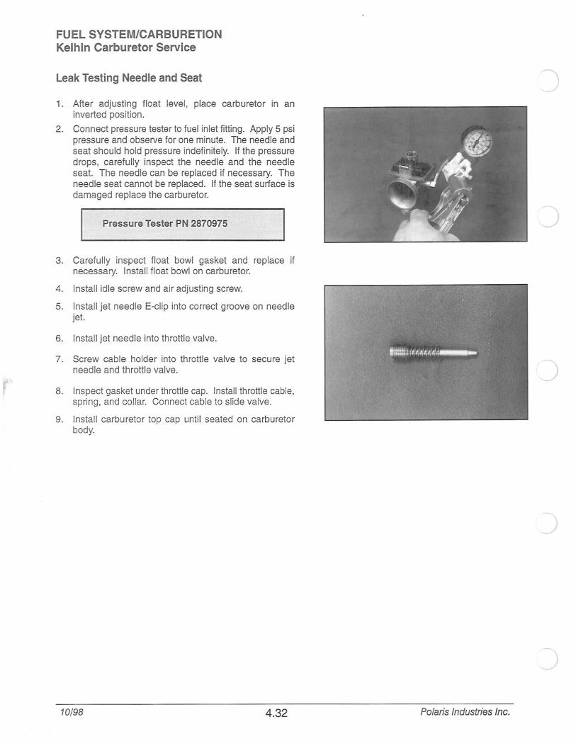
Leak Testing Needle and Seat
1. After adjusting float level, place carburetor in an inverted position.
2. Connect pressure tester to fuel inlet fitting. Apply 5 psi pressure and obseNe for one minute. The needle and seat should hold pressure indefinitely. If the pressure drops, carefully inspect the needle and the needle seat. The needle can be replaced if necessary. The needle seat cannot be replaced. If the seat surface is damaged replace the carburetor.
Pressure Tester PN 2870975
3. Carefully inspect float bowl gasket and replace if necessary. Install float bowl on carburetor.
4. Install idle screw and air adjusting screw.
5. Install jet needle E-clip into correct groove on needle jet.
6. Install jet needle into throttle valve.
7. Screw cable holder into throttle valve to secure jet needle and throttle valve.
8. Inspect gasket under throttle cap. Install throttle cable, spring, and collar. Connect cable to slide valve.
9. Install carburetor top cap until seated on carburetor body.
10/98 4.32
I
)
)
j
J
Polaris Industries Inc.
c
c
FUEL SYSTEM/CARBURETION Adjustments
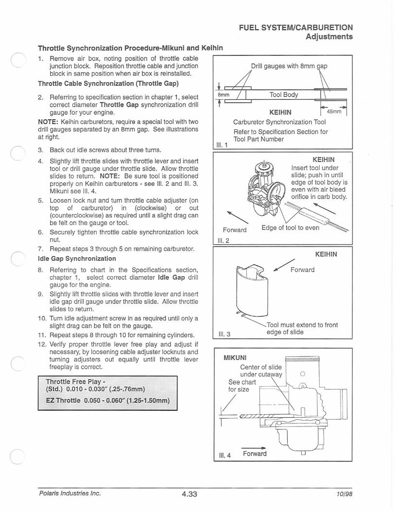
Throttle Synchronization Procedure-Mikuni and Keihin
1. Remove air box, noting position of throttle cable junction block. Reposition throttle cable and junction block in same position when air box is reinstalled.
~--------------------------------,
Drill gauges with 8mm ap
Throttle Cable Synchronization (Throttle Gap) _lc:c;t;:L--------------~=*=::::::1
2. Referring to specification section in chapter 1, select correct diameter Throttle Gap synchronization drill gauge for your engine.
NOTE: Keihin carburetors, require a special tool with two drill gauges separated by an 8mm gap. See illustrations at right.
3. Back out idle screws about three turns.
4. Slightly lift throttle sl ides with throttle lever and insert tool or drill gauge under throttle slide. Allow throttle slides to return. NOTE: Be sure tool is positioned properly on Keihin carburetors - see Ill. 2 and Ill. 3. Mikuni see Ill. 4.
5. Loosen lock nut and turn throttle cable adjuster (on top of carburetor) in (clockwise) or out (counterclockwise) as required until a slight drag can be felt on the gauge or tool.
6. Securely tighten throttle cable synchronization lock nut.
7. Repeat steps 3 through 5 on remaining carburetor.
Idle Gap Synchronization
8. Referring to chart in the Specifications section, chapter 1, select correct diameter Idle Gap drill gauge for the engine.
9. Slightly lift throttle slides with throttle lever and insert idle gap drill gauge under throttle slide. Allow throttle slides to return.
10. Turn idle adjustment screw in as required until only a slight drag can be felt on the gauge.
11. Repeat steps 8 through 10 for remaining cylinders.
12. Verify proper thrott le lever free play and adjust if necessary, by loosening cable adjuster locknuts and turning adjusters out equal ly until throttle lever freeplay is correct.
Throttle Free Play -(Std.) 0.010- 0.030" (.25-.76mm)
EZ Throttle 0.050- 0.060" (1.25-1.50mm)
Polaris Industries Inc. 4.33
Smm
Ill. 1
KEIHIN
Carburetor Synchronization Tool
Refer to Specification Section for Tool Part Number
KEIHIN Insert tool under slide; push in until edge of tool body is even with air bleed orifice in carb body.
Forward
Ill. 2
KEIHIN
~orward
~Tool must extend to front 111. 3 edge of slide
MIKUNI
Center of slide under cutaway
See chart for size F==~
Ill. 4 Forward
0
10/98
,f
FUEL SYSTEM/CARBURETION Mikuni TM-38 Carburetor Service
Wear eye protection when using compressed air or cleaning solvents. Review all fuel system warnings found on page 4.1 before proceeding.
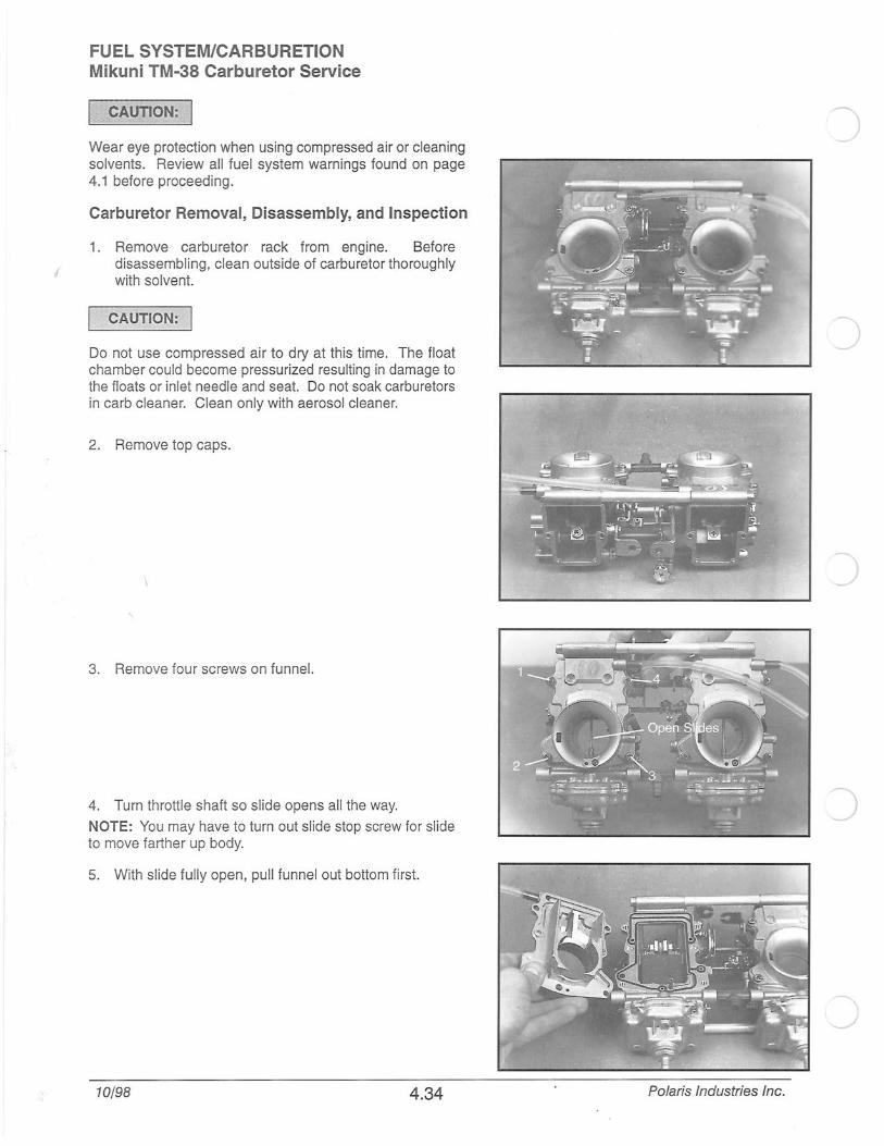
Carburetor Removal, Disassembly, and Inspection
1. Remove carburetor rack from engine. Before disassembling, clean outside of carburetor thoroughly with solvent.
CAUTION: I
Do not use compressed air to dry at this time. The float chamber could become pressurized resulting in damage to the floats or inlet needle and seat. Do not soak carburetors in carb cleaner. Clean only with aerosol cleaner.
2. Remove top caps.
3. Remove four screws on funnel.
4. Turn throttle shaft so slide opens all the way.
NOTE: You may have to turn out slide stop screw for slide to move farther up body.
5. With slide fully open, pull funnel out bottom first.
10/98 4.34 Polaris Industries Inc.

r
c
c
Disassembly Cont.
6. From top of carb, loosen allen head screw holding needle in position. Slide holding plate to side.
7. Reach into top of carb with a long nose pliers and pull out needle.
8. Inspect needle for wear.
9. Remove E-rings, packing, plate, spring , and rings connecting slide to lever.
Polaris Industries Inc. 4.35
FUEL SYSTEM/CARBURETION Mikuni TM-38 Carburetor Service
10/98
FUEL SYSTEM/CARBURETION Mikuni TM-38 Carburetor Service
Carburetor Disassembly Cont.
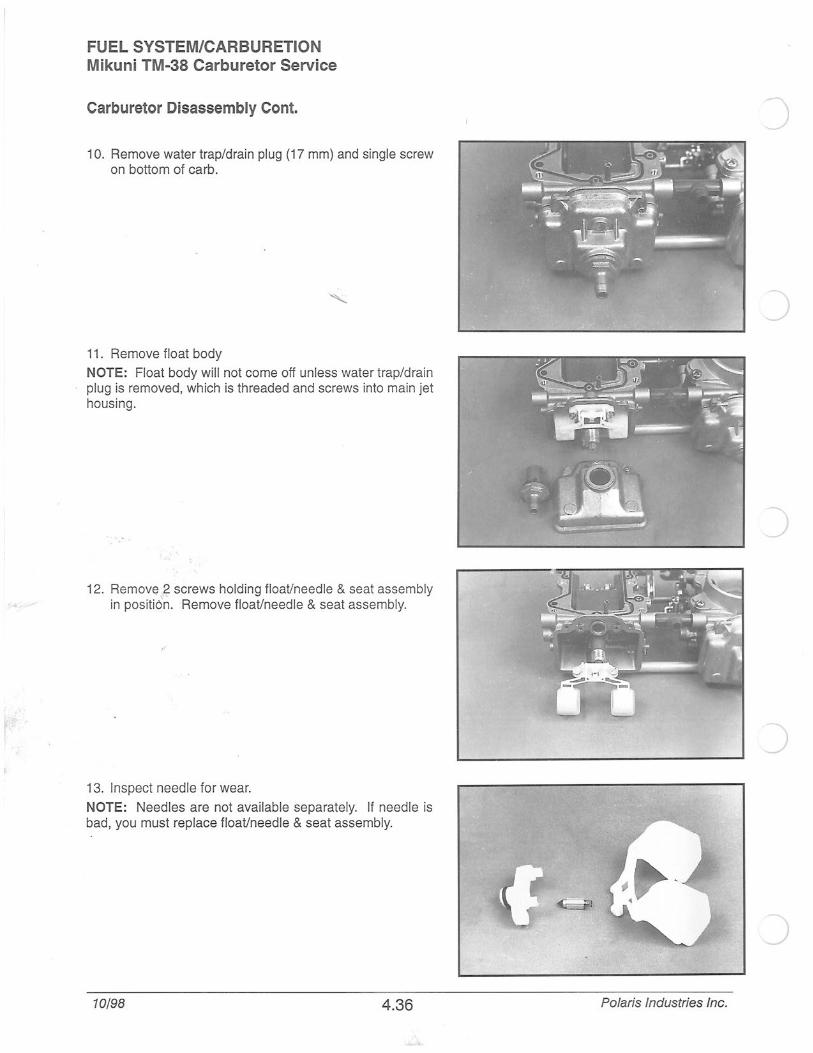
10. Remove water trap/drain plug (17 mm) and single screw on bottom of carb.
11. Remove float body
NOTE: Float body will not come off unless water trap/drain plug is removed, which is threaded and screws into main jet housing.
12. Remove 2 screws holding float/needle & seat assembly in positi6n. Remove float/needle & seat assembly.
,r
13. Inspect needle for wear.
NOTE: Needles are not available separately. If needle is bad, you must replace float/needle & seat assembly.
10/98 4.36
)
_)
Polaris Industries Inc.
( Carburetor Disassembly
c
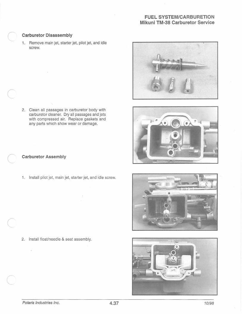
1 . Remove main jet, starter jet, pilot jet, and idle screw.
2. Clean all passages in carburetor body with carburetor cleaner. Dry all passages and jets with compressed air. Replace gaskets and any parts which show wear or damage.
c Carburetor Assembly
1. Install pilot jet, main jet, starter jet, and idle screw.
(
2. Install float/needle & seat assembly.
c Polaris Industries Inc. 4.37
FUEL SYSTEM/CARBURETION Mikuni TM-38 Carburetor Service
10/98
FUEL SYSTEM/CARBURETION Mikuni TM-38 Carburetor Service
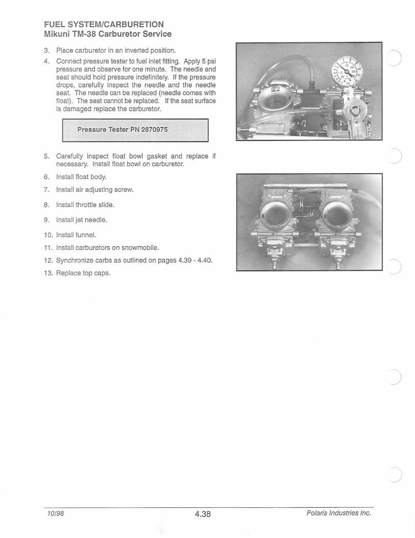
3. Place carburetor in an inverted position.
4. Connect pressure tester to fuel inlet fitting. Apply 5 psi pressure and observe for one minute. The needle and seat should hold pressure indefinitely. If the pressure drops, carefully inspect the need le and the needle seat. The needle can be replaced (needle comes with float). The seat cannot be replaced. If the seat surface is damaged replace the carburetor.
Pressure Tester PN 2870975
5. Carefully inspect float bowl gasket and replace if necessary. Install float bowl on carburetor.
6. Install float body.
7. Install air adjusting screw.
8. Install throttle slide.
9. Install jet needle.
10. Install funnel.
11. Install carburetors on snowmobile .
12. Synchronize carbs as outlined on pages 4.39 - 4.40.
13. Replace top caps.
10/98 4.38
J
Polaris Industries Inc.
(
r
c
Throttle Synchronization ProcedureMikuni TM-38 Flatslide Carburetors
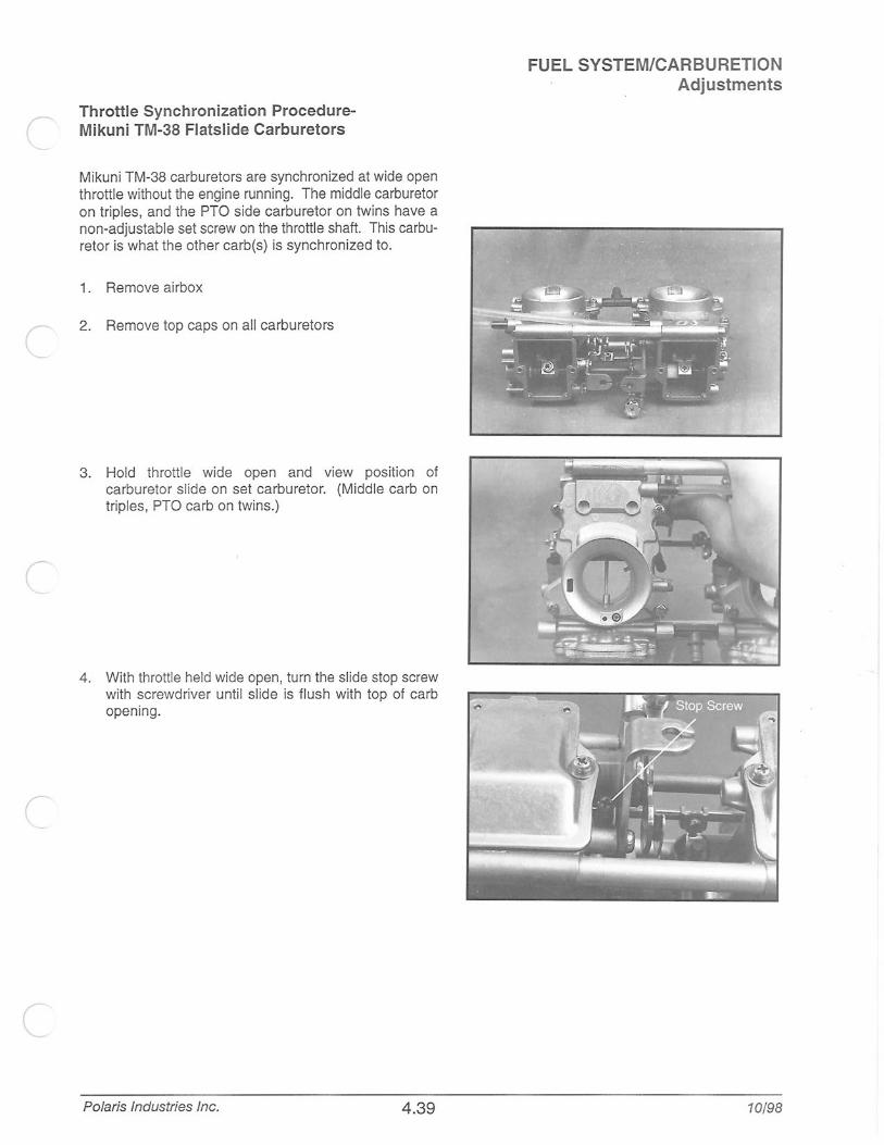
Mikuni TM-38 carburetors are synchronized at wide open throttle without the engine running. The middle carburetor on triples, and the PTO side carburetor on twins have a non-adjustable set screw on the throttle shaft. This carburetor is what the other carb(s) is synchronized to.
1. Remove airbox
2. Remove top caps on all carburetors
3. Hold throttle wide open and view position of carburetor slide on set carburetor. (Middle carb on triples, PTO carbon twins.)
4. With throttle held wide open, turn the slide stop screw with screwdriver until slide is flush with top of carb opening.
Polaris Industries Inc. 4 .39
FUEL SYSTEM/CARBURETION Adjustments
10/98

FUEL SYSTEM/CARBURETION Adjustments Throttle Synchronization ProcedureMikuni TM-38 Flatslide Carburetors
5. On remaining carb(s), loosen phillips head screw inside the offset nut.
6. When screw is loose, hold throttle to wide open. Turn offset nut until throttle slide is in same position as set carburetor.
7. Tighten phillips head screw.
8. Replace top caps.
10/98 4.40 Polaris Industries Inc.
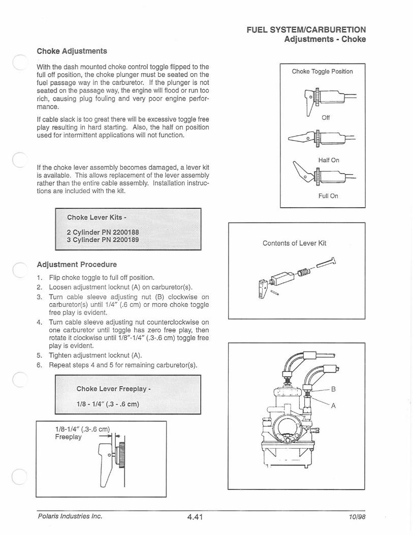
Choke Adjustments
With the dash mounted choke control toggle flipped to the full off position, the choke plunger must be seated on the fuel passage way in the carburetor. If the plunger is not seated on the passage way, the engine will flood or run too rich, causing plug fouling and very poor engine performance.
If cable slack is too great there will be excessive toggle free play resu lting in hard starting. Also, the half on position used for intermittent applications will not function.
If the choke lever assembly becomes damaged, a lever kit is available. This allows replacement of the lever assembly rather than the entire cable assembly. Installation instructions are included with the kit.
Choke Lever Kits -
2 Cylinder PN 2200188 3 Cylinder PN 2200189
Adjustment Procedure
1. Flip choke toggle to full off position.
2. Loosen adjustment locknut (A) on carburetor(s).
3. Turn cable sleeve adjusting nut (B) clockwise on carburetor(s) until 1/4" (.6 em) or more choke toggle free play is evident.
4. Turn cable sleeve adjusting nut counterclockwise on one carburetor until toggle has zero free play, then rotate it clockwise unti11/8"-1/4" (.3- .6 em) toggle free play is evident.
5. Tighten adjustment locknut (A).
6. Repeat steps 4 and 5 for remaining carburetor(s) .
Choke Lever Freeplay -
1/8 - 1/4" (.3- .6 em)
1/8-1/4" (.3-.6 em) Freeplay
Polaris Industries Inc. 4.41
FUEL SYSTEM/CARBURETION Adjustments - Choke
Choke Toggle Position
Full On
Contents of Lever Kit
10/98

FUEL SYSTEM/CARBURETION Primer Systems Domestic 600 & 700 Primer Systems
Primer Kit Schematic
46" Supply Line
4, 10 Line (3116,) _ 'ducer Adaptor - - ---.. ~[D}C (/- -u. 27" Primer Line
1" Primer Line H Check Val~~ . .
Tee Fi~ 4 Pnmec Lone
4" Primer Li ~-· PN Primer Primer
~Bodies
(2)~~0 0 0 \
Tee Fitting Primer kit part #2871889
1998 Domestic 600/700s, 1997 700 SKS and RMK
Fuel Inlet Line to Primer
/ r··~ 1 h r··-.. -CJ--~ r~
_ ___L_nj I \.:::::==================::=:J mU::ilJ::D CJ cl]O:l ~-··-··-··-··-··-·j
Fuel Out to Carburetors/
Standard primer routing diagram for 1999 600/700 twins
10/98 4.42 Polaris Industries Inc.
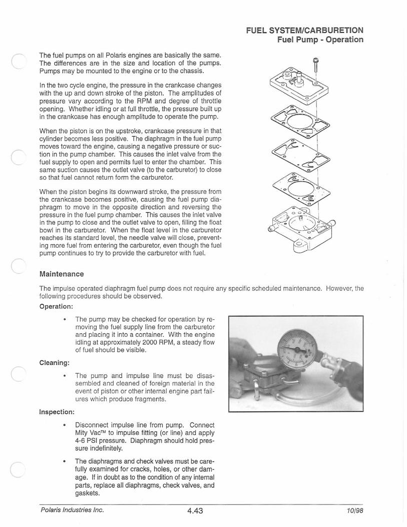
r The fuel pumps on all Polaris engines are basically the same. The differences are in the size and location of the pumps. Pumps may be mounted to the engine or to the chassis.
In the two cycle engine, the pressure in the crankcase changes with the up and down stroke of the piston. The amplitudes of pressure vary according to the RPM and degree of throttle opening. Whether idling or at full throttle, the pressure built up in the crankcase has enough amplitude to operate the pump.
When the piston is on the upstroke, crankcase pressure in that cylinder becomes less positive. The diaphragm in the fuel pump moves toward the engine, causing a negative pressure or suction in the pump chamber. This causes the inlet valve from the fuel supply to open and permits fuel to enter the chamber. Th is same suction causes the outlet valve (to the carburetor) to close so that fuel cannot return form the carburetor.
When the piston begins its downward stroke, the pressure from the crankcase becomes positive, causing the fuel pump diaphragm to move in the opposite direction and reversing the pressure in the fuel pump chamber. This causes the inlet valve in the pump to close and the outlet valve to open, filling the float bowl in the carburetor. When the float level in the carbu retor reaches its standard level, the needle valve will close, preventing more fuel from entering the carburetor, even though the fuel pump continues to try to provide the carburetor with fuel.
Maintenance
FUEL SYSTEM/CARBURETION Fuel Pump - Operation
The impulse operated diaphragm fuel pump does not require any specific scheduled maintenance. However, the following procedures should be observed.
Operation:
Cleaning:
Inspection:
The pump may be checked for operation by re moving the fuel supply line from the carburetor and placing it into a container. With the engine idling at approximately 2000 RPM, a steady flow of fuel should be visible.
The pump and impulse line must be disassembled and cleaned of foreign material in the event of piston or other internal engine part fail ures which produce fragments.
• Disconnect impulse line from pump. Connect Mity Vac™ to impulse fitting (or line) and apply 4-6 PSI pressure. Diaphragm should hold pressure indefinitely.
• The diaphragms and check valves must be carefully examined for cracks, holes, or other damage. If in doubt as to the condition of any internal parts, replace all diaphragms, check valves, and gaskets.
Polaris Industries Inc. 4.43 10/98

FUEL SYSTEM/CARBURETION Exploded View Fuel Pump
Taio Giken
Description of Parts 1. Vacuum (from crankcase) 2. Diaphragm 3. Gaskets 4. Check Valves 5. Fuel Outlets (to carbs) 6. Fuel Inlet (from tank)
10/98
3
4.44
1
/1~ ~2
Polaris Industries Inc.

Polaris Industries Inc.
FUEL SYSTEM/CARBURETION Exploded View -Twin Cylinder (Typical) Fuel Pump
Parts Description
1. Pump Body Assembly 2. Lower Gasket 3. Diaphragm 4. Upper Gasket 5. Screw (6 used) 6. Check Valve
4.45 10/98
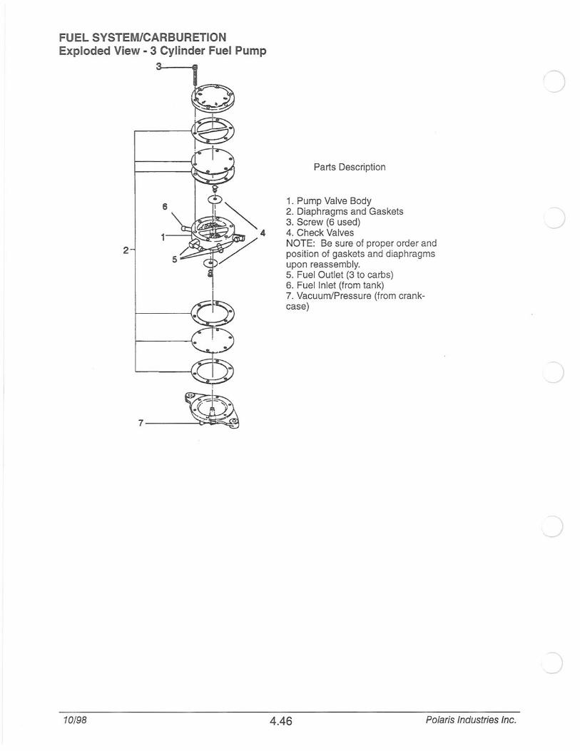
FUEL SYSTEM/CARBURETION Exploded View - 3 Cylinder Fuel Pump
I 0
2
10/98
Parts Description
1. Pump Valve Body 2. Diaphragms and Gaskets 3. Screw {6 used) 4. Check Valves NOTE: Be sure of proper order and position of gaskets and diaphragms upon reassembly. 5. Fuel Outlet (3 to carbs) 6. Fuel Inlet (from tank) 7. Vacuum/Pressure (from crankcase)
4.46 Polaris Industries Inc.
j

Polaris Industries Inc.
FUEL SYSTEM/CARBURETION Exploded View- Twin Cylinder Domestic Fuel Pump
4.47
Walbro Fuel Pump
NOTE: Individual parts are not available for domestic engine fuel pumps. If any internal parts are fau lty, the pump must be replaced.
10/98

FUEL SYSTEM/CARBURETION Water Trap Service
A WARNING
Fuel spillage will occur during this installation. Gasoline is extremely flammable and explosive under certain conditions.
A Do not smoke or allow open flames or sparks in or near the area where refueling is performed or where gasoline is stored.
'f Do not weld or operate a torch near the fuel system. Remove fuel tank before any chassis welding is per~ formed .
A If you get gasoline in your eyes or if you swallow gasoline, see your doctor immediately.
A If you spi ll gasoline on your skin or clothing, immediately wash it off with soap and water and change clothing.
'f Never start the engine or let it run in an enclosed area. Gasoline powered engine exhaust fumes are poison~ ous and can cause loss of consciousness and death in a short time.
1. Turn fuel valve off.
2. Remove air silencer.
3. Position a shop cloth or container below drain plug and water trap plug. Float
4. Remove drain plug and sealing 0 -Ring, or sl ide clamp upward and remove water trap plug.
5. Drain water/fuel. Clean trap with electrical contact cleaner and dry with compressed air.
6. Lightly grease 0 -ring and install water trap assembly into bottom of float bowl, or reinstall trap plug in hose and position. Tighten securely.
7. Turn fuel on, start engine and check for possible fuel leaks.
8. Reinstall air box.
The water traps should be periodically inspected and drained. Draining frequency will depend upon fuel supply, riding conditions, and fuel handling precautions.
10/98 4.48
Bowl
.,...._ 0-Ring
Drain Plug~
Clamp
--'.
Hose
I &--water Trap
Plug
Polaris Industries Inc.

c
FUEL SYSTEM/CARBURETION Troubleshooting
Fuel system diagnosis should follow a specific path, first examining the fuel tank, then the filters, fuel lines, vent lines, fuel pump, impulse hose, air box, exhaust system and finally the carburetors.
The following troubleshooting information assumes that the general mechanical condition of the engine (pistons, rings, bearings, etc.) is good.
When the fuel/air mixture is diagnosed as improper due to spark plug readings, clean the carburetor and blow its passages clear with compressed air. Use the spark plug firing end condition as a guide for further determination of whether the mixture is too rich or too lean.
Use the throttle lever to determine at what degree of throttle valve opening the problem exists.
CONDITION SYMPTOMS
Mixture Too Rich -Black spark plug tip; plug fouling -Heavy exhaust smoke -Engine runs worse after warm up -Eng ine "loads up"
Mixture Too Lean -Spark plug electrodes white -Fluctuation in engine speed -Power loss -Engine overheats -Cylinder scoring I Holing pistons -Backfiring - detonation -Throttle diagnostic opening check points
Poor Fuel Mileage -Incorrect ignition timing -Improper track tension (too tight) -Incorrect carburetor jetting -Fuel leaks (lines, fittings, fuel pump) -Needle and seat leaks -Plugged exhaust -Carburetor vent line problems -Clutching incorrect for conditions I worn belt
Troubleshooting Tips, 0-1/4 Throttle: Pilot air screw misadjusted
Pilot jet of wrong size, loose, or obstructed
Obstruction of pilot jet
• Pilot jet loose
Choke plunger not seating (rich)
Carburetor mounting air leak (lean)
Crankshaft seal air leak (lean)
Fuel pump diaphragm damaged (rich)
Float level incorrect
• Air bleed obstructed
Polaris Industries Inc. 4.49 10/98

FUEL SYSTEM/CARBURETION Troubleshooting
Troubleshooting Tips, 1/4-3/8 Throttle: • Obstruction in main jet or needle jet
• Jet needle worn or out of adjustment
• Pilot system malfunction
• Incorrect throttle valve cutaway
Troubleshooting Tips, 3/8-3/4 Throttle: Main jet incorrect size or clogged (lean)
Needle jet damaged or loose
Needle jet/jet needle worn (rich)
• E-clip position incorrect for altitude and temperature
Troubleshooting Tips, Full Throttle:
10/98
Main jet size (rich or lean)
Fuel filter blocked (lean)
• Fuel vent lines or check valves plugged
• Exhaust system plugged
Air box restricted
Fuel pump weak
Exhaust leaking into engine compartment (rich)
• Water in float bowl (lean)
4.50 Polaris Industries Inc.
Related Documents