Chapter 4 Electrical Principles

Chapter 4 Electrical Principles. Radio Mathematics Volts, Amps, Resistance / Impedance Can’t see Use equations to describe Graphs are pictures of equations.
Dec 22, 2015
Welcome message from author
This document is posted to help you gain knowledge. Please leave a comment to let me know what you think about it! Share it to your friends and learn new things together.
Transcript
Chapter 4Electrical Principles

Radio Mathematics
Volts, Amps, Resistance / Impedance
• Can’t see
• Use equations to describe
• Graphs are pictures of equations
• Two types of graphs that show the same data in two different ways

Rectangular Coordinates
• Graph is composed of two axis, horizontal (x) and vertical (y)
• The point (0,0) is called the origin
• Data point is identified as a (x,y) data pair

Polar Coordinates
• Graph is composed of a fixed point called a pole (analogous to origin)
• Data point (called a ray) is identified by a distance from the pole and an angle from the horizontal axis (counter clock wise is positive)
• Angles are measured in degrees and radians– One cycle / circle = 360
degrees = 2 π radians (1 radian ≈ 57.3°)
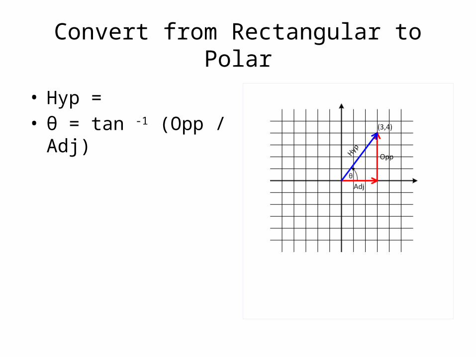
Convert from Rectangular to Polar
• Hyp = • θ = tan -1 (Opp / Adj)

Convert from Polar to Rectangular
• Radius (r) = Hyp• Adj = r * cos θ• Opp = r * sin θ

Complex numbers / coordinatesImaginary numbers
= ? = 6 = * = 2 * 3 = 6 = ? = * = 5 *
• is defined as “imaginary number“• Mathematicians use i, Electrical Engineers use j
because “i" is used to indicate instantaneous current

Complex Coordinates
• Combine real & imaginary numbers (real + j imaginary)

Convert Rectangular ˂˃ Polar
Rectangular to Polar• Hyp = • 5 = • θ = tan -1 (Opp / Adj) • 53.1⁰ = tan -1 (4 / 3)Polar to Rectangular• Adj = r * cos θ• 3 = 4.2 * cos(-45⁰)• Opp = r * sin θ• -3 = 4.2 * sin (-45⁰)

Complex numbers MathAdd/Subtract - Use Rectangular form• (a + j b) + (c + j d) = (a + c) +j (b + d)• (2 + j3) + (4 + j1) = (6 + j4)
Multiply/Divide - Use Polar form• a θ1 * b θ2 = (a * b) (θ1 + θ2 )
• a θ1 / b θ2 = (a / b) (θ1 - θ2 )
• 6 45⁰ / 2 30⁰ = (6 / 2) (45 - 30 ) = 3 15⁰
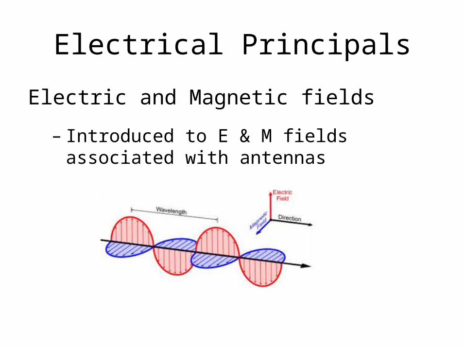
Electrical Principals
Electric and Magnetic fields
– Introduced to E & M fields associated with antennas

RC and RL Time Constants
• Electrical energy
– Can be detected as voltage differences between two points
– Capacitors store and release electrical energy
– Capacitors will resist a change in voltage
• Magnetic energy
– Is detected by moving electrical charges (current)
– Inductors store and release magnetic energy
– Inductors will resist a change in current movement
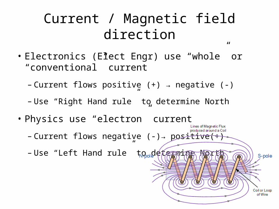
Current / Magnetic field direction
• Electronics (Elect Engr) use “whole” or “conventional” current
– Current flows positive (+) → negative (-)
– Use “Right Hand rule” to determine North
• Physics use “electron” current
– Current flows negative (-)→ positive(+)
– Use “Left Hand rule” to determine North

Time Constant
• RC circuit - The time it takes to charge (or discharge) a capacitor (VC) depends on the size of the resistor
• RL circuit - The time it takes for current to increase (or decrease) through an inductor (iL) also depends on the size of the resistor.
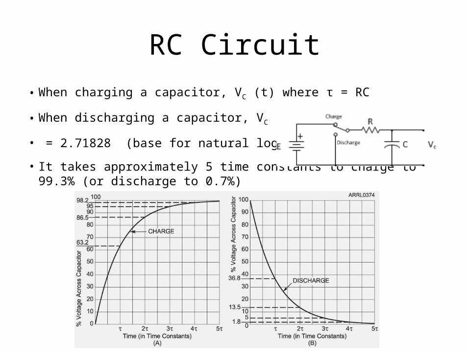
RC Circuit• When charging a capacitor, VC (t) where τ = RC
• When discharging a capacitor, VC (t)
• = 2.71828 (base for natural logarithms)
• It takes approximately 5 time constants to charge to 99.3% (or discharge to 0.7%)
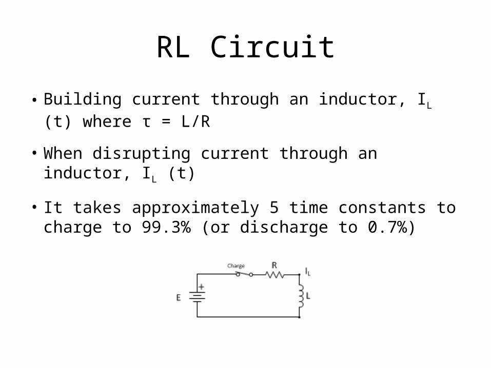
RL Circuit
• Building current through an inductor, IL (t) where τ = L/R
• When disrupting current through an inductor, IL (t)
• It takes approximately 5 time constants to charge to 99.3% (or discharge to 0.7%)

Phase Angle
• Phase Angle refers to time
– 1 cycle of frequency x = 1/x seconds
– 1 cycle = 360⁰
– Phase angle is measured between similar points on each waveform
• Resistors dissipate energy
– voltage & current are“in phase”
Phase Angle
• Capacitors and Inductors store / release energy
– Unlike in Resistors, voltage & current waveforms do NOT rise and fall together
• ELI the ICE man
– Inductors – voltage (E) leads current (I)
– Capacitors – current (I) leads voltage (E)
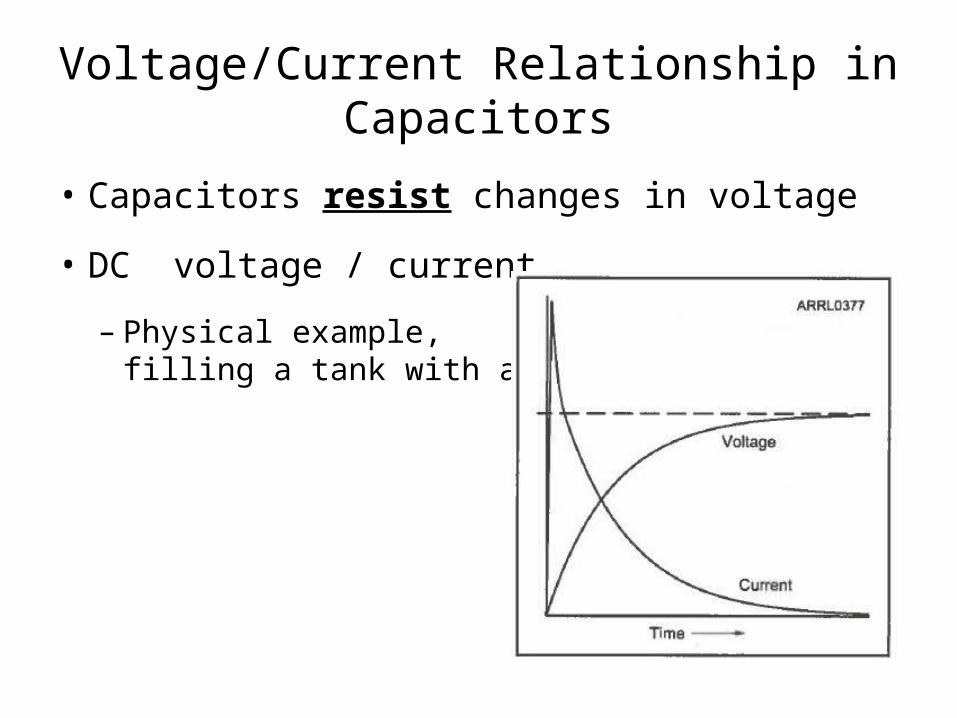
Voltage/Current Relationship in Capacitors
• Capacitors resist changes in voltage
• DC voltage / current
– Physical example,filling a tank with air

AC Voltage/Current phase relationship in Capacitors
ICE - current LEADS voltage (VC)
– voltage (VC) LAGS current
– (current is reference) phase angle is -90⁰(I)
(VC)

Electric (field strength) energy is stored and released twice each cycle
• Max current at 0 volts
• 0 current at Maximum volts
• Current leads voltage (ICE)(I)
(VC)
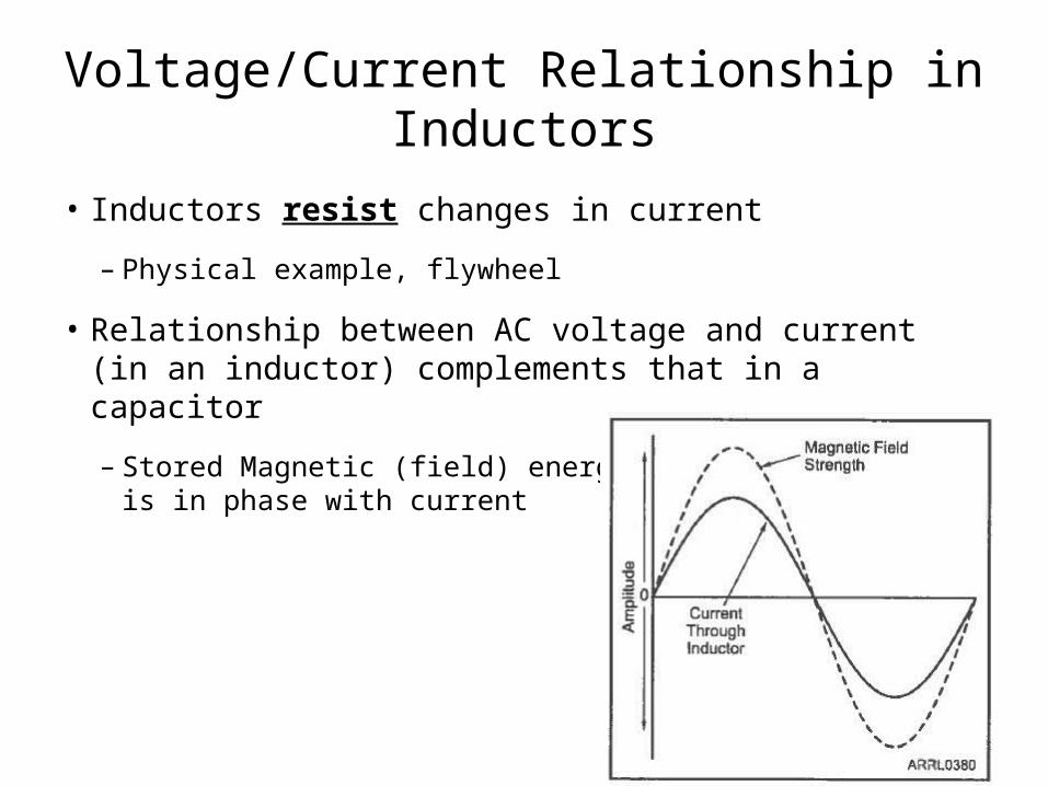
Voltage/Current Relationship in Inductors
• Inductors resist changes in current
– Physical example, flywheel
• Relationship between AC voltage and current (in an inductor) complements that in a capacitor
– Stored Magnetic (field) energyis in phase with current
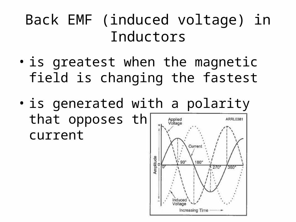
Back EMF (induced voltage) in Inductors
• is greatest when the magnetic field is changing the fastest
• is generated with a polarity that opposes the change in current
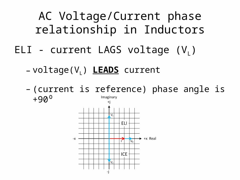
AC Voltage/Current phase relationship in Inductors
ELI - current LAGS voltage (VL)
– voltage(VL) LEADS current
– (current is reference) phase angle is +90⁰

Resistance versus Reactance
• Resistance is the opposition to the passage of (DC or AC) current (ohm Ω)
• Reactance is the opposition to the AC current flow through an inductor or capacitance
– Inductive reactance
– Capacitive reactance
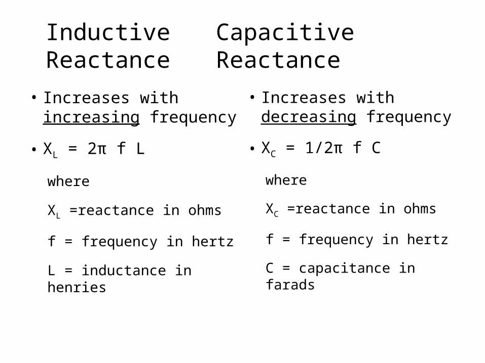
Inductive CapacitiveReactance Reactance
• Increases with increasing frequency
• XL = 2π f L
where
XL =reactance in ohms
f = frequency in hertz
L = inductance in henries
• Increases with decreasing frequency
• XC = 1/2π f C
where
XC =reactance in ohms
f = frequency in hertz
C = capacitance in farads

Complex Impedance
• Impedance (Z) is composed of two components, resistance and reactance
• Reactance can be either inductive or capacitive
• Resistance and Reactance may be connected either in series or parallel
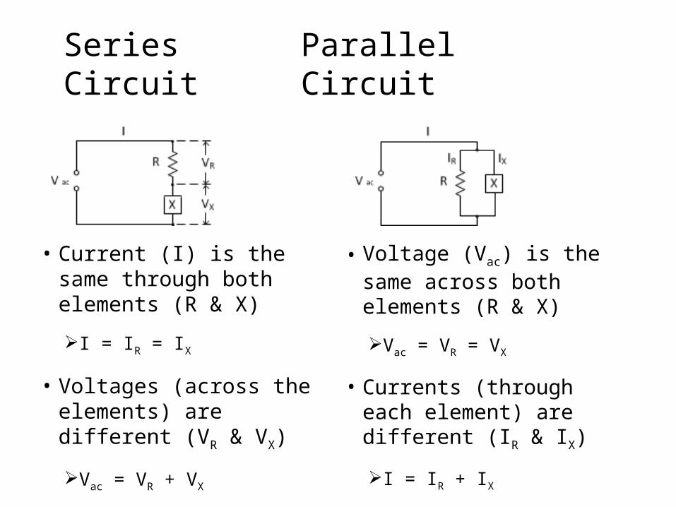
Series ParallelCircuit Circuit
• Current (I) is the same through both elements (R & X)
I = IR = IX
• Voltages (across the elements) are different (VR & VX)
Vac = VR + VX
• Voltage (Vac) is the same across both elements (R & X)
Vac = VR = VX
• Currents (through each element) are different (IR & IX)
I = IR + IX

Complex Impedance
The phase relationship between the current (I) and voltage (for the whole circuit, Vac) can be between 0⁰ and ±90⁰
• The phase angle depends on the relative amounts of resistance and reactance
• The sign of the angle depends on the type of the reactive element
– Inductive reactance produces a positive angle
– Capacitive reactance produces a negative angle
Reduce multiple elements to one equivalent element
• Multiple resistors to one resistor
• Multiple reactive elements (capacitors / inductors) to one reactive element
– Capacitors (-90⁰) and inductors (+90⁰) have opposite phase angles
– Combining capacitors and inductors will result in a smaller TOTAL reactance (adding the negative and positive angles will cancel each other)
– If the capacitors and inductors have EQUIVALENT reactive values, they will cancel each other (angle=0⁰ thus X=0), resulting in only a resistive element (R)

Calculate Impedance
Calculate Reactance of 20 mH inductor at 10 kHz
• XL = 2π f L
• XL = 2 x 3.14 x (10 x 103) x (20 x 10-3)
• XL = 1256Ω

Calculate Impedance
Since we aren’t given a VT , we assume I=1
• VR = 1000v (voltage in phase with current)
• VL = 1256v (voltage leads current by 90⁰, “ELI”)• = 1605
• VT = 1605 51.5⁰

Calculate Impedance
What if we would have had a 20,000 mF capacitor?
• XC = 1/(2π f C)
• XC = 1/[2 x 3.14 x (10 x 103) x (20,000 x 10-6)]
• XC = 1/1256Ω = 1256 -90⁰
• OR current leads voltage by 90⁰, “ICE”

Calculating Impedances and Phase Angles - BASIC Rules
• Impedances in series add together
• Admittance is the reciprocal of impedance
Y =
• Admittances in parallel add together
• Inductive and capacitive reactance in series cancel

Refresher
• Conductivity (G) is the reciprocal of Resistance (R)
G = units of siemens (S)
• Susceptance (B) is the reciprocal of Reactance (Y)
B = units of siemens (S)
• Taking the reciprocal of an angle, changes its sign
37⁰ = and -73⁰ =

Refresher (cont)
• Voltage determines the reference for phase angle
– Current is the reference
– If voltage LEADS current (ELI) -> Positive phase angle
– If voltage LAGS current (ICE) -> Negative phase angle
• Voltage LAGS current = current leads voltage
Reactive Power and Power Factor
• Power = Voltage x Current (DC circuit)
• Reactive Power = VoltageRMS x CurrentRMS
– AC circuit, when voltage & current are in phase
• Apparent Power
– Does not take into consideration phase angle
– Expressed in units of volt-amperes (VA)
– AKA reactive, nonproductive or wattless power (VAR)
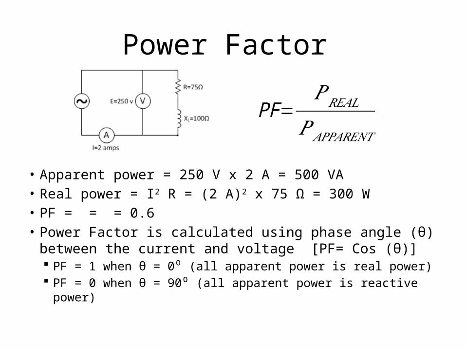
Power Factor
• Apparent power = 250 V x 2 A = 500 VA• Real power = I2 R = (2 A)2 x 75 Ω = 300 W• PF = = = 0.6• Power Factor is calculated using phase angle (θ)
between the current and voltage [PF= Cos (θ)] PF = 1 when θ = 0⁰ (all apparent power is real power) PF = 0 when θ = 90⁰ (all apparent power is reactive power)
PF=𝑃𝑅𝐸𝐴𝐿
𝑃 𝐴𝑃𝑃𝐴𝑅𝐸𝑁𝑇

Resonant Circuits• Circuits with different inductive and capacitive reactances
o Series – different voltages
o Parallel – different currents
• Circuit is said to be resonant when XL = XC
o Series – VC will cancel VI , leaving only VR
o Parallel - IC will cancel II , leaving only IR
• Calculation of Resonant frequency
o XL = XC
o 2π f L = 1/2π f C
o Resonant frequency (fr)

Impedance of Resonant Series Circuits
• At resonant VL = VC
Equal amounts of energy are stored in each component The energy being supplied will cause voltages across the
inductor and capacitor to build to multiple times the source voltage
XL cancels XC, resulting in maximum current Voltage and current are in phase
Series Circuits Same current VL is 180⁰ out of
phase with VC
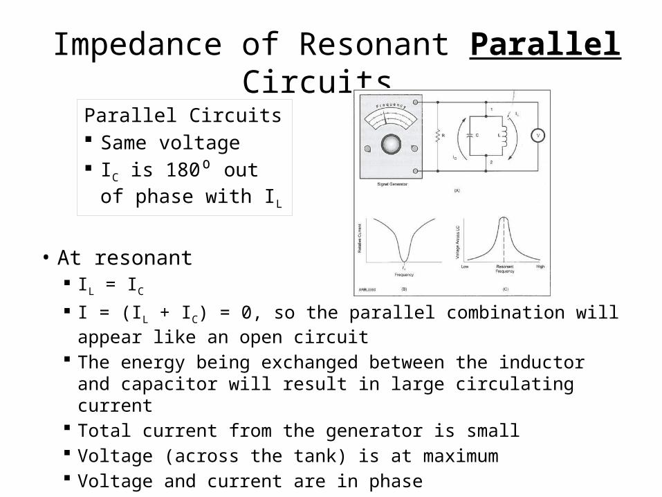
Impedance of Resonant Parallel Circuits
• At resonant IL = IC
I = (IL + IC) = 0, so the parallel combination will appear like an open circuit
The energy being exchanged between the inductor and capacitor will result in large circulating current
Total current from the generator is small Voltage (across the tank) is at maximum Voltage and current are in phase
Parallel Circuits Same voltage IC is 180⁰ out of phase
with IL

Q and Bandwidth of Resonant Circuits
• Practical components
– Can be represented as ideal components (inductor or capacitor) in series with a resistor
– That resistance dissipates some of the stored energy
• Quality factor ( Q )
– Represents how close to an ideal component is the practical component
– Ratio of how much energy is stored to how much energy is dissipated
– Energy losses of a capacitor is usually much less than that for an inductor
– Thus the Q of the inductor is usually the limiting factor of the Q of a resonant circuit
– The only way to raise the Q of an inductor or capacitor is by using components with less internal resistance
Q and Bandwidth of Resonant Circuits (cont)
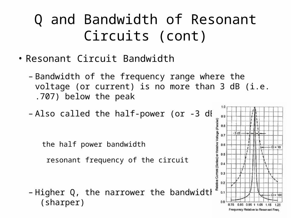
• Resonant Circuit Bandwidth
– Bandwidth of the frequency range where the voltage (or current) is no more than 3 dB (i.e. .707) below the peak
– Also called the half-power (or -3 dB) bandwidth
the half power bandwidth
resonant frequency of the circuit
– Higher Q, the narrower the bandwidth (sharper)
Q and Bandwidth of Resonant Circuits (cont)
• Skin Effect and Q
– As frequency increases
• more of the current travels closer to the surface of the wire
• the “effective” resistance of the wire increases
– HF – outer few thousandths of an inch
– VHF & UHF – outer few ten-thousandths

Magnetic Cores
• Inductors store magnetic energy, creating reactance
• Wire can be wound around various material
– Air is relatively inefficient way to store magnetic energy
– Magnetic material increases the storage of energy (and the inductance)
• Inductance is a function of
– Number of turns of wire on the core
– Core materials permeability (air = 1)

Magnetic Cores (cont)
• Select the core material carefully
– Perform over a desired frequency range
– Temperature stability
• Core shape
– Affects magnetic field (shape around the inductor)
– Magnetic field of one inductor can interact with nearby components (coupling)
– Toroid cores reduce unwanted coupling by keeping the magnetic field contained in the “donut”

Magnetic Cores (cont)
• Calculating Inductance
– Or number of turns
– Each time the wire passes through the core, it counts as a turn
• Ferrite bead
– Small core, slipped over component leads, often used as suppressors for VHF & UHF oscillations

Questions
Related Documents