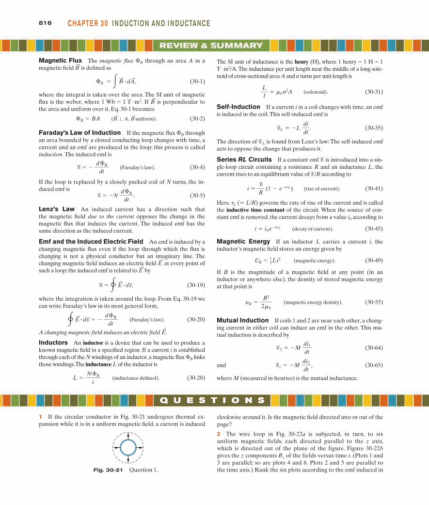
Magnetic Flux The magnetic flux B through an area A in a magnetic field is defined as (30-1) where the integral is taken over the area. The SI unit of magnetic flux is the weber, where 1 Wb 1 T m 2 . If is perpendicular to the area and uniform over it, Eq. 30-1 becomes (30-2) Faraday’s Law of Induction If the magnetic flux B through an area bounded by a closed conducting loop changes with time, a current and an emf are produced in the loop; this process is called induction. The induced emf is (Faraday’s law). (30-4) If the loop is replaced by a closely packed coil of N turns, the in- duced emf is (30-5) Lenz’s Law An induced current has a direction such that the magnetic field due to the current opposes the change in the magnetic flux that induces the current. The induced emf has the same direction as the induced current. Emf and the Induced Electric Field An emf is induced by a changing magnetic flux even if the loop through which the flux is changing is not a physical conductor but an imaginary line. The changing magnetic field induces an electric field at every point of such a loop; the induced emf is related to by (30-19) where the integration is taken around the loop. From Eq. 30-19 we can write Faraday’s law in its most general form, (Faraday’s law). (30-20) A changing magnetic field induces an electric field . Inductors An inductor is a device that can be used to produce a known magnetic field in a specified region. If a current i is established through each of the N windings of an inductor, a magnetic flux B links those windings.The inductance L of the inductor is (inductance defined). (30-28) L N B i E : E : ds : d B dt E : ds : , E : E : N d B dt . d B dt (B : A, B : uniform). B BA B : B B : dA : , B : The SI unit of inductance is the henry (H), where 1 henry 1H 1 T m 2 /A. The inductance per unit length near the middle of a long sole- noid of cross-sectional area A and n turns per unit length is (solenoid). (30-31) Self-Induction If a current i in a coil changes with time, an emf is induced in the coil.This self-induced emf is (30-35) The direction of L is found from Lenz’s law: The self-induced emf acts to oppose the change that produces it. Series RL Circuits If a constant emf is introduced into a sin- gle-loop circuit containing a resistance R and an inductance L, the current rises to an equilibrium value of /R according to (rise of current). (30-41) Here t L ( L/R) governs the rate of rise of the current and is called the inductive time constant of the circuit. When the source of con- stant emf is removed, the current decays from a value i 0 according to (decay of current). (30-45) Magnetic Energy If an inductor L carries a current i, the inductor’s magnetic field stores an energy given by (magnetic energy). (30-49) If B is the magnitude of a magnetic field at any point (in an inductor or anywhere else), the density of stored magnetic energy at that point is (magnetic energy density). (30-55) Mutual Induction If coils 1 and 2 are near each other, a chang- ing current in either coil can induce an emf in the other. This mu- tual induction is described by (30-64) and (30-65) where M (measured in henries) is the mutual inductance. 1 M di 2 dt , 2 M di 1 dt u B B 2 2 0 U B 1 2 Li 2 i i 0 e t/ L i R (1 e t/ L ) L L di dt . L l 0 n 2 A 816 CHAPTER 30 INDUCTION AND INDUCTANCE 1 If the circular conductor in Fig. 30-21 undergoes thermal ex- pansion while it is in a uniform magnetic field, a current is induced clockwise around it. Is the magnetic field directed into or out of the page? 2 The wire loop in Fig. 30-22a is subjected, in turn, to six uniform magnetic fields, each directed parallel to the z axis, which is directed out of the plane of the figure. Figure 30-22b gives the z components B z of the fields versus time t. (Plots 1 and 3 are parallel; so are plots 4 and 6. Plots 2 and 5 are parallel to the time axis.) Rank the six plots according to the emf induced in Fig. 30-21 Question 1.

Welcome message from author
This document is posted to help you gain knowledge. Please leave a comment to let me know what you think about it! Share it to your friends and learn new things together.
Transcript
Magnetic Flux The magnetic flux �B through an area A in amagnetic field is defined as
(30-1)
where the integral is taken over the area. The SI unit of magneticflux is the weber, where 1 Wb � 1 T � m2. If is perpendicular tothe area and uniform over it, Eq. 30-1 becomes
(30-2)
Faraday’s Law of Induction If the magnetic flux �B throughan area bounded by a closed conducting loop changes with time, acurrent and an emf are produced in the loop; this process is calledinduction. The induced emf is
(Faraday’s law). (30-4)
If the loop is replaced by a closely packed coil of N turns, the in-duced emf is
(30-5)
Lenz’s Law An induced current has a direction such thatthe magnetic field due to the current opposes the change in themagnetic flux that induces the current. The induced emf has thesame direction as the induced current.
Emf and the Induced Electric Field An emf is induced by achanging magnetic flux even if the loop through which the flux ischanging is not a physical conductor but an imaginary line. Thechanging magnetic field induces an electric field at every point ofsuch a loop; the induced emf is related to by
(30-19)
where the integration is taken around the loop. From Eq. 30-19 wecan write Faraday’s law in its most general form,
(Faraday’s law). (30-20)
A changing magnetic field induces an electric field .
Inductors An inductor is a device that can be used to produce aknown magnetic field in a specified region. If a current i is establishedthrough each of the N windings of an inductor,a magnetic flux �B linksthose windings.The inductance L of the inductor is
(inductance defined). (30-28)L �N�B
i
E:
� E:
� ds: � � d�B
dt
� � � E:
� ds:,
E:
E:
� � �N d�B
dt.
� � � d�B
dt
(B:
� A, B: uniform). �B � BA
B:
�B � � B:
� dA:
,
B:
The SI unit of inductance is the henry (H), where 1 henry � 1 H � 1T �m2/A.The inductance per unit length near the middle of a long sole-noid of cross-sectional area A and n turns per unit length is
(solenoid). (30-31)
Self-Induction If a current i in a coil changes with time, an emfis induced in the coil.This self-induced emf is
(30-35)
The direction of �L is found from Lenz’s law: The self-induced emfacts to oppose the change that produces it.
Series RL Circuits If a constant emf � is introduced into a sin-gle-loop circuit containing a resistance R and an inductance L, thecurrent rises to an equilibrium value of �/R according to
(rise of current). (30-41)
Here tL (� L/R) governs the rate of rise of the current and is calledthe inductive time constant of the circuit. When the source of con-stant emf is removed, the current decays from a value i0 according to
(decay of current). (30-45)
Magnetic Energy If an inductor L carries a current i, theinductor’s magnetic field stores an energy given by
(magnetic energy). (30-49)
If B is the magnitude of a magnetic field at any point (in aninductor or anywhere else), the density of stored magnetic energyat that point is
(magnetic energy density). (30-55)
Mutual Induction If coils 1 and 2 are near each other, a chang-ing current in either coil can induce an emf in the other. This mu-tual induction is described by
(30-64)
and (30-65)
where M (measured in henries) is the mutual inductance.
�1 � �M di2
dt,
�2 � �M di1
dt
uB �B2
2�0
UB � 12Li2
i � i0 e�t/�L
i ��
R (1 � e�t/�L)
�L � �L didt
.
Ll
� �0 n2A
816 CHAPTE R 30 I N DUCTION AN D I N DUCTANCE
1 If the circular conductor in Fig. 30-21 undergoes thermal ex-pansion while it is in a uniform magnetic field, a current is induced
clockwise around it. Is the magnetic field directed into or out of thepage?
2 The wire loop in Fig. 30-22a is subjected, in turn, to sixuniform magnetic fields, each directed parallel to the z axis,which is directed out of the plane of the figure. Figure 30-22bgives the z components Bz of the fields versus time t. (Plots 1 and3 are parallel; so are plots 4 and 6. Plots 2 and 5 are parallel tothe time axis.) Rank the six plots according to the emf induced inFig. 30-21 Question 1.
halliday_c30_791-825hr.qxd 11-12-2009 12:19 Page 816
Bull
Typewritten Text
** View All Solutions Here **
Bull
Typewritten Text
** View All Solutions Here **
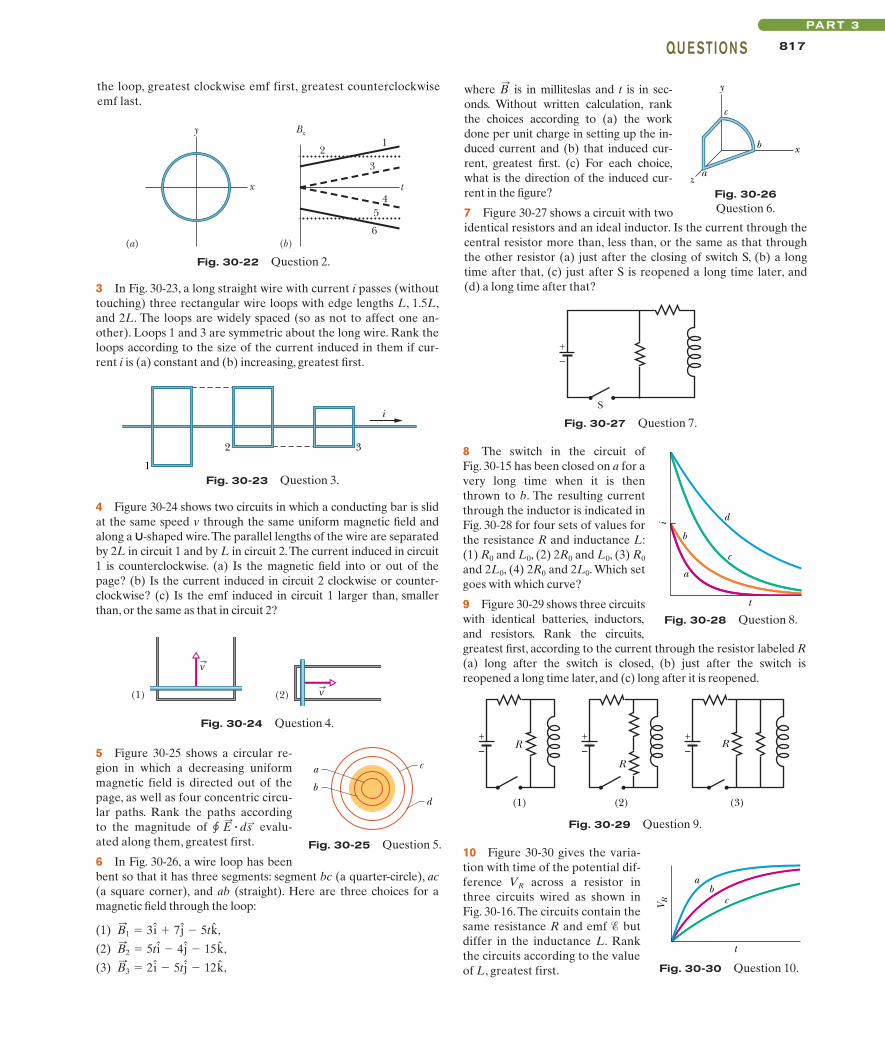
8 The switch in the circuit of Fig. 30-15 has been closed on a for avery long time when it is thenthrown to b. The resulting currentthrough the inductor is indicated inFig. 30-28 for four sets of values forthe resistance R and inductance L:(1) R0 and L0, (2) 2R0 and L0, (3) R0
and 2L0, (4) 2R0 and 2L0. Which setgoes with which curve?
9 Figure 30-29 shows three circuitswith identical batteries, inductors,and resistors. Rank the circuits,greatest first, according to the current through the resistor labeled R(a) long after the switch is closed, (b) just after the switch isreopened a long time later, and (c) long after it is reopened.
5 Figure 30-25 shows a circular re-gion in which a decreasing uniformmagnetic field is directed out of thepage, as well as four concentric circu-lar paths. Rank the paths accordingto the magnitude of evalu-ated along them, greatest first.
6 In Fig. 30-26, a wire loop has beenbent so that it has three segments: segment bc (a quarter-circle), ac(a square corner), and ab (straight). Here are three choices for amagnetic field through the loop:
(1) ,
(2) ,
(3) ,B:
3 � 2i � 5t j � 12k
B:
2 � 5t i � 4j � 15k
B:
1 � 3i 7j � 5tk
� E:
� ds:
817QU E STION SPART 3
where is in milliteslas and t is in sec-onds. Without written calculation, rankthe choices according to (a) the workdone per unit charge in setting up the in-duced current and (b) that induced cur-rent, greatest first. (c) For each choice,what is the direction of the induced cur-rent in the figure?
7 Figure 30-27 shows a circuit with twoidentical resistors and an ideal inductor. Is the current through thecentral resistor more than, less than, or the same as that throughthe other resistor (a) just after the closing of switch S, (b) a longtime after that, (c) just after S is reopened a long time later, and(d) a long time after that?
B:
Fig. 30-22 Question 2.
x
y
21
3
45
6
t
Bz
(a) (b)
the loop, greatest clockwise emf first, greatest counterclockwiseemf last.
Fig. 30-23 Question 3.
i
32
1
4 Figure 30-24 shows two circuits in which a conducting bar is slidat the same speed v through the same uniform magnetic field andalong a U-shaped wire.The parallel lengths of the wire are separatedby 2L in circuit 1 and by L in circuit 2.The current induced in circuit1 is counterclockwise. (a) Is the magnetic field into or out of thepage? (b) Is the current induced in circuit 2 clockwise or counter-clockwise? (c) Is the emf induced in circuit 1 larger than, smallerthan, or the same as that in circuit 2?
Fig. 30-24 Question 4.
v
v
(1) (2)
c
db
a
Fig. 30-25 Question 5.
Fig. 30-27 Question 7.
+ –
S
Fig. 30-28 Question 8.
t
i
a
b
c
d
Fig. 30-29 Question 9.
+–
(1) (2)
+–R
R
+–
R
(3)
3 In Fig. 30-23, a long straight wire with current i passes (withouttouching) three rectangular wire loops with edge lengths L, 1.5L,and 2L. The loops are widely spaced (so as not to affect one an-other). Loops 1 and 3 are symmetric about the long wire. Rank theloops according to the size of the current induced in them if cur-rent i is (a) constant and (b) increasing, greatest first.
z
x
y
c
b
a
Fig. 30-26Question 6.
10 Figure 30-30 gives the varia-tion with time of the potential dif-ference VR across a resistor inthree circuits wired as shown inFig. 30-16. The circuits contain thesame resistance R and emf � butdiffer in the inductance L. Rankthe circuits according to the valueof L, greatest first. Fig. 30-30 Question 10.
V R
t
ab
c
halliday_c30_791-825hr.qxd 11-12-2009 12:19 Page 817
Bull
Typewritten Text
** View All Solutions Here **
Bull
Typewritten Text
** View All Solutions Here **

818 CHAPTE R 30 I N DUCTION AN D I N DUCTANCE
with emf � � 6.00 mV, a resistance R, and a small wire loop ofarea 5.0 cm2. For the time interval t � 10 s to t � 20 s, an externalmagnetic field is set up throughout the loop. The field is uniform,its direction is into the page in Fig. 30-35a, and the field magni-tude is given by B � at, where B is in teslas, a is a constant, and tis in seconds. Figure 30-35b gives the current i in the circuit be-fore, during, and after the external field is set up. The verticalaxis scale is set by is � 2.0 mA. Find the constant a in the equa-tion for the field magnitude.
•7 In Fig. 30-36, the magnetic fluxthrough the loop increases accordingto the relation �B � 6.0t2 7.0t, where�B is in milliwebers and t is in seconds.(a) What is the magnitude of the emfinduced in the loop when t � 2.0 s? (b)Is the direction of the current throughR to the right or left?
•8 A uniform magnetic field is per-pendicular to the plane of a circularloop of diameter 10 cm formed fromwire of diameter 2.5 mm and resistivity 1.69 � 10�8 � m. At whatrate must the magnitude of change to induce a 10 A current inthe loop?
•9 A small loop of area 6.8 mm2 is placed inside a long solenoidthat has 854 turns/cm and carries a sinusoidally varying current i ofamplitude 1.28 A and angular frequency 212 rad/s.The central axesof the loop and solenoid coincide.What is the amplitude of the emfinduced in the loop?
••10 Figure 30-37 shows a closed loop of wire that consists of apair of equal semicircles, of radius 3.7 cm, lying in mutually per-pendicular planes. The loop was formed by folding a flat circularloop along a diameter until the two halves became perpendicularto each other. A uniform magnetic field of magnitude 76 mT isdirected perpendicular to the fold diameter and makes equal an-gles (of 45°) with the planes of the semicircles. The magnetic fieldis reduced to zero at a uniform rate during a time interval of 4.5ms. During this interval, what are the (a) magnitude and (b) di-rection (clockwise or counterclockwise when viewed along thedirection of ) of the emf induced in the loop?B
:
B:
B:
B:
sec. 30-4 Lenz’s Law•1 In Fig. 30-31, a circular loop of wire 10 cmin diameter (seen edge-on) is placed with itsnormal at an angle u � 30° with the directionof a uniform magnetic field of magnitude 0.50T.The loop is then rotated such that rotates ina cone about the field direction at the rate 100rev/min; angle u remains unchanged during theprocess.What is the emf induced in the loop?
•2 A certain elastic conducting material isstretched into a circular loop of 12.0 cm radius.It is placed with its plane perpendicular to a uniform 0.800 T mag-netic field. When released, the radius of the loop starts to shrink atan instantaneous rate of 75.0 cm/s. What emf is induced in the loopat that instant?
•3 In Fig. 30-32, a120-turn coil of radius 1.8 cm and re-sistance 5.3 is coaxial with a solenoid of 220 turns/cm anddiameter 3.2 cm. The solenoid cur-rent drops from 1.5 A to zero in timeinterval �t � 25 ms. What current isinduced in the coil during �t?
•4 A wire loop of radius 12 cm andresistance 8.5 is located in a uni-form magnetic field that changesin magnitude as given in Fig. 30-33.The vertical axis scale is set by Bs �0.50 T, and the horizontal axis scaleis set by ts � 6.00 s. The loop’s planeis perpendicular to .What emf is induced in the loop during time in-tervals (a) 0 to 2.0 s, (b) 2.0 s to 4.0 s,and (c) 4.0 s to 6.0 s?
•5 In Fig. 30-34, a wire forms aclosed circular loop, of radius R �2.0 m and resistance 4.0 . Thecircle is centered on a long straightwire; at time t � 0, the current inthe long straight wire is 5.0 Arightward. Thereafter, the currentchanges according to i � 5.0 A �(2.0 A/s2)t2. (The straight wire is insulated; so there is no electricalcontact between it and the wire of the loop.) What is the magni-tude of the current induced in the loop at times t � 0?
•6 Figure 30-35a shows a circuit consisting of an ideal battery
B:
B:
WWWSSM
N:
B:
N:
B
Nθ
Loop
Fig. 30-31Problem 1.
Fig. 30-32 Problem 3.
Coil
Solenoid
Fig. 30-33 Problem 4.
Bs
0 ts
B (
T)
t (s)
R
Fig. 30-34 Problem 5.
Fig. 30-35 Problem 6.
is
0t (s)
30
i (m
A)
R
(a) (b)
Fig. 30-36 Problem 7.
R
B
Fig. 30-37 Problem 10.
Magneticfield
Tutoring problem available (at instructor’s discretion) in WileyPLUS and WebAssign
SSM Worked-out solution available in Student Solutions Manual
• – ••• Number of dots indicates level of problem difficulty
Additional information available in The Flying Circus of Physics and at flyingcircusofphysics.com
WWW Worked-out solution is at
ILW Interactive solution is at http://www.wiley.com/college/halliday
halliday_c30_791-825hr.qxd 11-12-2009 12:19 Page 818
Bull
Typewritten Text
** View All Solutions Here **
Bull
Typewritten Text
** View All Solutions Here **

819PROB LE M SPART 3
••11 A rectangular coil of N turns and of length a and width b isrotated at frequency f in a uniform magnetic field , as indicated inFig. 30-38. The coil is connected to co-rotating cylinders, againstwhich metal brushes slide to make contact. (a) Show that the emfinduced in the coil is given (as a function of time t) by
� � 2p fNabB sin(2p f t) � �0 sin(2p f t).
This is the principle of the commercial alternating-current gen-erator. (b) What value of Nab gives an emf with �0 � 150 Vwhen the loop is rotated at 60.0 rev/s in a uniform magneticfield of 0.500 T?
B:
••15 A square wire loop with2.00 m sides is perpendicular to auniform magnetic field, with halfthe area of the loop in the field asshown in Fig. 30-41. The loop con-tains an ideal battery with emf � �20.0 V. If the magnitude of thefield varies with time according toB � 0.0420 � 0.870t, with B in tes-las and t in seconds, what are (a)the net emf in the circuit and (b)the direction of the (net) currentaround the loop?
••16 Figure 30-42a shows a wire that forms a rectangle (W � 20 cm, H � 30 cm) and has a resistance of 5.0 m. Its inte-rior is split into three equal areas, with magnetic fields , and
. The fields are uniform within each region and directly out of orinto the page as indicated. Figure 30-42b gives the change in the zcomponents Bz of the three fields with time t; the vertical axis scaleis set by Bs � 4.0 mT and Bb � �2.5Bs, and the horizontal axis scaleis set by ts � 2.0 s. What are the (a) magnitude and (b) direction ofthe current induced in the wire?
B:
3
B:
1, B:
2b
a
R
Sliding contactsB
Fig. 30-38 Problem 11.
••12 In Fig. 30-39, a wire loop of lengths L �40.0 cm and W � 25.0 cm lies in a magnetic field . What are the (a) magnitude and (b)direction (clockwise or counterclockwise—or“none”if 0) of the emf induced in the loop if
What are (c) � and(d) the direction if What are (e) and (f) the direction if
What are (g) and (h) the direction ifWhat are (i) and (j) the direction if
••13 One hundred turns of (insulated) copper wire arewrapped around a wooden cylindrical core of cross-sectional area1.20 � 10 �3 m2. The two ends of the wire are connected to a resis-tor.The total resistance in the circuit is 13.0 . If an externally ap-plied uniform longitudinal magnetic field in the core changesfrom 1.60 T in one direction to 1.60 T in the opposite direction,how much charge flows through a point in the circuit during thechange?
••14 In Fig. 30-40a, a uniform magnetic field increases inmagnitude with time t as given by Fig. 30-40b, where the verti-cal axis scale is set by Bs � 9.0 mT and the horizontal scale isset by ts � 3.0 s. A circular conducting loop of area 8.0 � 10�4
m2 lies in the field, in the plane of the page. The amount ofcharge q passing point A on the loop is given in Fig. 30-40c as afunction of t, with the vertical axis scale set by qs � 6.0 mC andthe horizontal axis scale again set by ts � 3.0 s. What is theloop’s resistance?
B:
ILW
B:
� (5.00 � 10 �2 T/m �s)yt i?�B
:� (3.00 � 10�2 T/m �s)xt j?
�B:
� (8.00 � 10 �2 T/m �s)ytk?�
B:
� (6.00 � 10 �2 T/s)tk?B:
� (4.00 � 10 �2 T/m)yk?� �
�B:
Fig. 30-39Problem 12.
W
L
y
x
(a) (b) (c)
AB
Bs
0t (s)
ts
B (
mT
)
qs
0t (s)
ts
q (m
C)
Fig. 30-40 Problem 14.
H
W
B1
B2
B3
y
x
t (s)
ts
1 2
3
Bs
0
–Bb
Bz (
T)
µ
(a) (b)
Fig. 30-42 Problem 16.
••17 A small circular loop of area 2.00 cm2 is placed in the planeof, and concentric with, a large circular loop of radius 1.00 m. Thecurrent in the large loop is changed at a constant rate from 200 Ato �200 A (a change in direction) in a time of 1.00 s, starting at t � 0. What is the magnitude of the magnetic field at the centerof the small loop due to the current in the large loop at (a) t � 0,(b) t � 0.500 s, and (c) t � 1.00 s? (d) From t � 0 to t � 1.00 s, is reversed? Because the inner loop is small, assume is uniformover its area. (e) What emf is induced in the small loop at t � 0.500 s?
••18 In Fig. 30-43, two straightconducting rails form a right an-gle. A conducting bar in contactwith the rails starts at the vertexat time t � 0 and moves with aconstant velocity of 5.20 m/salong them. A magnetic field withB � 0.350 T is directed out of thepage. Calculate (a) the flux through the triangle formed by therails and bar at t � 3.00 s and (b) the emf around the triangle atthat time. (c) If the emf is � � at n, where a and n are constants,what is the value of n?
••19 An electric generator contains a coil of 100 turns ofwire, each forming a rectangular loop 50.0 cm by 30.0 cm. The coil
ILW
B:
B:
B:
Fig. 30-41 Problem 15.
B
bat
Fig. 30-43 Problem 18.
B
v
halliday_c30_791-825hr.qxd 11-12-2009 12:19 Page 819
Bull
Typewritten Text
** View All Solutions Here **
Bull
Typewritten Text
** View All Solutions Here **

•••28 In Fig. 30-49, a rectangularloop of wire with length a � 2.2 cm,width b � 0.80 cm, and resistanceR � 0.40 m is placed near an infi-nitely long wire carrying current i � 4.7 A. The loop is then movedaway from the wire at constantspeed v � 3.2 mm/s. When the cen-ter of the loop is at distancer � 1.5b, what are (a) the magnitude of the magnetic flux throughthe loop and (b) the current induced in the loop?
sec. 30-5 Induction and Energy Transfers•29 In Fig. 30-50, a metal rod is forced to move with constant ve-locity along two parallel metal rails, connected with a strip ofmetal at one end. A magnetic field of magnitude B � 0.350 Tpoints out of the page. (a) If the rails are separated by L = 25.0 cmand the speed of the rod is 55.0 cm/s, what emf is generated? (b) Ifthe rod has a resistance of 18.0 and the rails and connector have
v:
•••27 As seen in Fig. 30-48, a square loop of wire has sides oflength 2.0 cm. A magnetic field is directed out of the page; its mag-nitude is given by B � 4.0t2y, where B is in teslas, t is in seconds,and y is in meters. At t � 2.5 s, what are the (a) magnitude and (b)direction of the emf induced in the loop?
ILW
820 CHAPTE R 30 I N DUCTION AN D I N DUCTANCE
is placed entirely in a uniform magnetic field with magnitude B �3.50 T and with initially perpendicular to the coil’s plane. Whatis the maximum value of the emf produced when the coil is spun at1000 rev/min about an axis perpendicular to ?
••20 At a certain place, Earth’s magnetic field has magnitude B � 0.590 gauss and is inclined downward at an angle of 70.0° tothe horizontal. A flat horizontal circular coil of wire with a radiusof 10.0 cm has 1000 turns and a total resistance of 85.0 . It isconnected in series to a meter with 140 resistance. The coil isflipped through a half-revolution about a diameter, so that it isagain horizontal. How much charge flows through the meter dur-ing the flip?
••21 In Fig. 30-44, a stiff wire bentinto a semicircle of radius a � 2.0 cmis rotated at constant angular speed 40rev/s in a uniform 20 mT magneticfield. What are the (a) frequency and(b) amplitude of the emf induced inthe loop?
••22 A rectangular loop (area �0.15 m2) turns in a uniform mag-netic field, B � 0.20 T.When the an-gle between the field and the normal to the plane of the loop is p/2rad and increasing at 0.60 rad/s,what emf is induced in the loop?
••23 Figure 30-45 showstwo parallel loops of wire havinga common axis. The smaller loop(radius r) is above the larger loop(radius R) by a distance x � R.Consequently, the magnetic fielddue to the counterclockwise currenti in the larger loop is nearly uniformthroughout the smaller loop.Suppose that x is increasing at theconstant rate dx/dt � v. (a) Find anexpression for the magnetic flux through the area of the smallerloop as a function of x. (Hint: See Eq. 29-27.) In the smaller loop,find (b) an expression for the induced emf and (c) the direction ofthe induced current.
••24 A wire is bent into three cir-cular segments, each of radius r �10 cm, as shown in Fig. 30-46. Eachsegment is a quadrant of a circle, ablying in the xy plane, bc lying in theyz plane, and ca lying in the zxplane. (a) If a uniform magneticfield points in the positive x di-rection, what is the magnitude ofthe emf developed in the wire whenB increases at the rate of 3.0 mT/s?(b) What is the direction of the cur-rent in segment bc?
•••25 Two long, parallel copper wires of diameter 2.5 mmcarry currents of 10 A in opposite directions. (a) Assuming thattheir central axes are 20 mm apart, calculate the magnetic flux permeter of wire that exists in the space between those axes. (b) Whatpercentage of this flux lies inside the wires? (c) Repeat part (a) forparallel currents.
B:
SSM
B:
B:
•••26 For the wire arrangement in Fig. 30-47, a � 12.0 cm and b �16.0 cm. The current in the long straight wire is i � 4.50t2 � 10.0t,where i is in amperes and t is in seconds. (a) Find the emf in thesquare loop at t � 3.00 s. (b) What is the direction of the inducedcurrent in the loop?
Fig. 30-44 Problem 21.
B
R
a
Fig. 30-45 Problem 23.
i
r
R
x
Fig. 30-46 Problem 24.
r
r
r
a
b
c
z
y
x
Fig. 30-47 Problem 26.
ba
b
i
y
x
B
Fig. 30-48 Problem 27.
b
a
r
i
v
Fig. 30-49 Problem 28.
Fig. 30-50 Problems 29 and 35.
L
B
v
halliday_c30_791-825hr.qxd 11-12-2009 12:19 Page 820
Bull
Typewritten Text
** View All Solutions Here **
Bull
Typewritten Text
** View All Solutions Here **

•37 A long solenoid has a diameter of 12.0 cm.When acurrent i exists in its windings, a uniform magnetic field of magnitudeB � 30.0 mT is produced in its interior. By decreasing i, the field iscaused to decrease at the rate of 6.50 mT/s. Calculate the magnitudeof the induced electric field (a) 2.20 cm and (b) 8.20 cm from the axisof the solenoid.
••38 A circular region in anxy plane is penetrated by auniform magnetic field in the posi-tive direction of the z axis. Thefield’s magnitude B (in teslas) in-creases with time t (in seconds) ac-cording to B � at, where a is aconstant. The magnitude E of theelectric field set up by that in-crease in the magnetic field isgiven by Fig. 30-55 versus radial distance r ; the vertical axis scaleis set by Es � 300 mN/C, and the horizontal axis scale is set by rs � 4.00 cm. Find a.
••39 The magnetic field of a cylindrical magnet that has apole-face diameter of 3.3 cm can be varied sinusoidally between29.6 T and 30.0 T at a frequency of 15 Hz. (The current in a wirewrapped around a permanent magnet is varied to give this varia-tion in the net field.) At a radial distance of 1.6 cm, what is the am-plitude of the electric field induced by the variation?
ILWSSM
821PROB LE M SPART 3
•31 If 50.0 cm of copper wire (diameter � 1.00 mm)is formed into a circular loop and placed perpendicular to a uni-form magnetic field that is increasing at the constant rate of 10.0mT/s, at what rate is thermal energy generated in the loop?
•32 A loop antenna of area 2.00 cm2 and resistance 5.21 m isperpendicular to a uniform magnetic field of magnitude 17.0 mT.The field magnitude drops to zero in 2.96 ms. How much thermalenergy is produced in the loop by the change in field?
••33 Figure 30-52 shows a rod oflength L � 10.0 cm that is forced tomove at constant speed v � 5.00m/s along horizontal rails. The rod,rails, and connecting strip at theright form a conducting loop. Therod has resistance 0.400 ; the restof the loop has negligible resis-tance. A current i � 100 A throughthe long straight wire at distance a � 10.0 mm from the loop sets upa (nonuniform) magnetic fieldthrough the loop. Find the (a) emfand (b) current induced in the loop. (c) At what rate is thermal en-ergy generated in the rod? (d) What is the magnitude of the forcethat must be applied to the rod to make it move at constant speed?(e) At what rate does this force dowork on the rod?
••34 In Fig. 30-53, a long rectan-gular conducting loop, of width L,resistance R, and mass m, is hungin a horizontal, uniform magneticfield that is directed into thepage and that exists only aboveline aa. The loop is then dropped;during its fall, it accelerates until itreaches a certain terminal speedvt. Ignoring air drag, find an ex-pression for vt.
B:
ILWSSM
••35 The conducting rod shown in Fig. 30-50 has length L and isbeing pulled along horizontal, frictionless conducting rails at aconstant velocity . The rails are connected at one end with ametal strip. A uniform magnetic field , directed out of the page,fills the region in which the rod moves. Assume that L � 10 cm,v � 5.0 m/s, and B � 1.2 T. What are the (a) magnitude and (b)direction (up or down the page) of the emf induced in the rod?What are the (c) size and (d) direction of the current in the con-ducting loop? Assume that the resistance of the rod is 0.40 andthat the resistance of the rails and metal strip is negligibly small.(e) At what rate is thermal energy being generated in the rod? (f)What external force on the rod is needed to maintain ? (g) Atwhat rate does this force do work on the rod?
sec. 30-6 Induced Electric Fields•36 Figure 30-54 shows two circular regions R1 and R2 with radiir1 � 20.0 cm and r2 � 30.0 cm. In R1 there is a uniform magneticfield of magnitude B1 � 50.0 mT directed into the page, and in R2
there is a uniform magnetic field of magnitude B2 � 75.0 mT di-rected out of the page (ignore fringing). Both fields are decreas-ing at the rate of 8.50 mT/s. Calculate for (a) path 1, (b)path 2, and (c) path 3.
� E:
� ds:
v:
B:
v:
(a) (b) (c)
is
0t (s)
ts
i sol (
A)
Es
0t (s)
tsE
th (
nJ)
Fig. 30-51 Problem 30.
L
a
i
Bv
Fig. 30-52 Problem 33.
B
mg
L
a a
Fig. 30-53 Problem 34.
R2R1
Path 1
Path 2
Path 3
Fig. 30-54 Problem 36.
E (
N/C
)µ
Es
0r (cm)
rs
Fig. 30-55 Problem 38.
negligible resistance, what is the current in the rod? (c) At whatrate is energy being transferred to thermal energy?
•30 In Fig. 30-51a, a circular loop of wire is concentric with a sole-noid and lies in a plane perpendicular to the solenoid’s central axis.The loop has radius 6.00 cm. The solenoid has radius 2.00 cm, con-sists of 8000 turns/m, and has a current isol varying with time t asgiven in Fig. 30-51b, where the vertical axis scale is set by is � 1.00A and the horizontal axis scale is set by ts � 2.0 s. Figure 30-51cshows, as a function of time, the energy Eth that is transferred tothermal energy of the loop; the vertical axis scale is set by Es �100.0 nJ.What is the loop’s resistance?
halliday_c30_791-825hr.qxd 11-12-2009 12:19 Page 821
Bull
Typewritten Text
** View All Solutions Here **
Bull
Typewritten Text
** View All Solutions Here **
822 CHAPTE R 30 I N DUCTION AN D I N DUCTANCE
sec. 30-7 Inductors and Inductance•40 The inductance of a closely packed coil of 400 turns is 8.0mH. Calculate the magnetic flux through the coil when the currentis 5.0 mA.
•41 A circular coil has a 10.0 cm radius and consists of 30.0closely wound turns of wire. An externally produced magneticfield of magnitude 2.60 mT is perpendicular to the coil. (a) If nocurrent is in the coil, what magnetic flux links its turns?(b) When the current in the coil is 3.80 A in a certain direction,the net flux through the coil is found to vanish. What is theinductance of the coil?
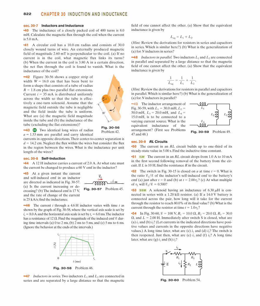
••42 Figure 30-56 shows a copper strip ofwidth W � 16.0 cm that has been bent toform a shape that consists of a tube of radius R � 1.8 cm plus two parallel flat extensions.Current i � 35 mA is distributed uniformlyacross the width so that the tube is effec-tively a one-turn solenoid. Assume that themagnetic field outside the tube is negligibleand the field inside the tube is uniform.What are (a) the magnetic field magnitudeinside the tube and (b) the inductance of thetube (excluding the flat extensions)?
••43 Two identical long wires of radius a � 1.53 mm are parallel and carry identicalcurrents in opposite directions. Their center-to-center separation isd � 14.2 cm. Neglect the flux within the wires but consider the fluxin the region between the wires. What is the inductance per unitlength of the wires?
sec. 30-8 Self-Induction•44 A 12 H inductor carries a current of 2.0 A.At what rate mustthe current be changed to produce a 60 V emf in the inductor?
•45 At a given instant the currentand self-induced emf in an inductorare directed as indicated in Fig. 30-57.(a) Is the current increasing or de-creasing? (b) The induced emf is 17 V,and the rate of change of the currentis 25 kA/s; find the inductance.
••46 The current i through a 4.6 H inductor varies with time t asshown by the graph of Fig. 30-58, where the vertical axis scale is set by is � 8.0 A and the horizontal axis scale is set by ts � 6.0 ms.The inductorhas a resistance of 12 . Find the magnitude of the induced emf � dur-ing time intervals (a) 0 to 2 ms, (b) 2 ms to 5 ms, and (c) 5 ms to 6 ms.(Ignore the behavior at the ends of the intervals.)
field of one cannot affect the other. (a) Show that the equivalentinductance is given by
Leq � L1 L2.
(Hint: Review the derivations for resistors in series and capacitorsin series. Which is similar here?) (b) What is the generalization of(a) for N inductors in series?
••48 Inductors in parallel. Two inductors L1 and L2 are connectedin parallel and separated by a large distance so that the magneticfield of one cannot affect the other. (a) Show that the equivalentinductance is given by
(Hint: Review the derivations for resistors in parallel and capacitorsin parallel. Which is similar here?) (b) What is the generalization of(a) for N inductors in parallel?
••49 The inductor arrangement ofFig. 30-59, with L1 � 30.0 mH, L2 �50.0 mH, L3 � 20.0 mH, and L4 �15.0 mH, is to be connected to avarying current source. What is theequivalent inductance of thearrangement? (First see Problems47 and 48.)
sec. 30-9 RL Circuits•50 The current in an RL circuit builds up to one-third of itssteady-state value in 5.00 s. Find the inductive time constant.
•51 The current in an RL circuit drops from 1.0 A to 10 mAin the first second following removal of the battery from the cir-cuit. If L is 10 H, find the resistance R in the circuit.
•52 The switch in Fig. 30-15 is closed on a at time t � 0. What isthe ratio �L/� of the inductor’s self-induced emf to the battery’semf (a) just after t � 0 and (b) at t � 2.00tL? (c) At what multipleof tL will �L/� � 0.500?
•53 A solenoid having an inductance of 6.30 mH is con-nected in series with a 1.20 k resistor. (a) If a 14.0 V battery isconnected across the pair, how long will it take for the currentthrough the resistor to reach 80.0% of its final value? (b) What is thecurrent through the resistor at time t � 1.0tL?
•54 In Fig. 30-60, � � 100 V, R1 � 10.0 , R2 � 20.0 , R3 � 30.0, and L � 2.00 H. Immediately after switch S is closed, what are(a) i1 and (b) i2? (Let currents in the indicated directions have posi-tive values and currents in the opposite directions have negativevalues.) A long time later, what are (c) i1 and (d) i2? The switch isthen reopened. Just then, what are (e) i1 and (f) i2? A long timelater, what are (g) i1 and (h) i2?
SSM
ILW
1Leq
�1
L1
1L2
.
Fig. 30-57 Problem 45.
i L
Fig. 30-58 Problem 46.
is
0 ts
i (A
)
t (ms)L
+–
Si1
i2
R1 R3
R2
Fig. 30-60 Problem 54.
Fig. 30-59 Problem 49.
L3L2
L4
L1
Fig. 30-56Problem 42.
i
i
iW
R
••47 Inductors in series. Two inductors L1 and L2 are connected inseries and are separated by a large distance so that the magnetic
halliday_c30_791-825hr.qxd 11-12-2009 12:19 Page 822
Bull
Typewritten Text
** View All Solutions Here **
Bull
Typewritten Text
** View All Solutions Here **
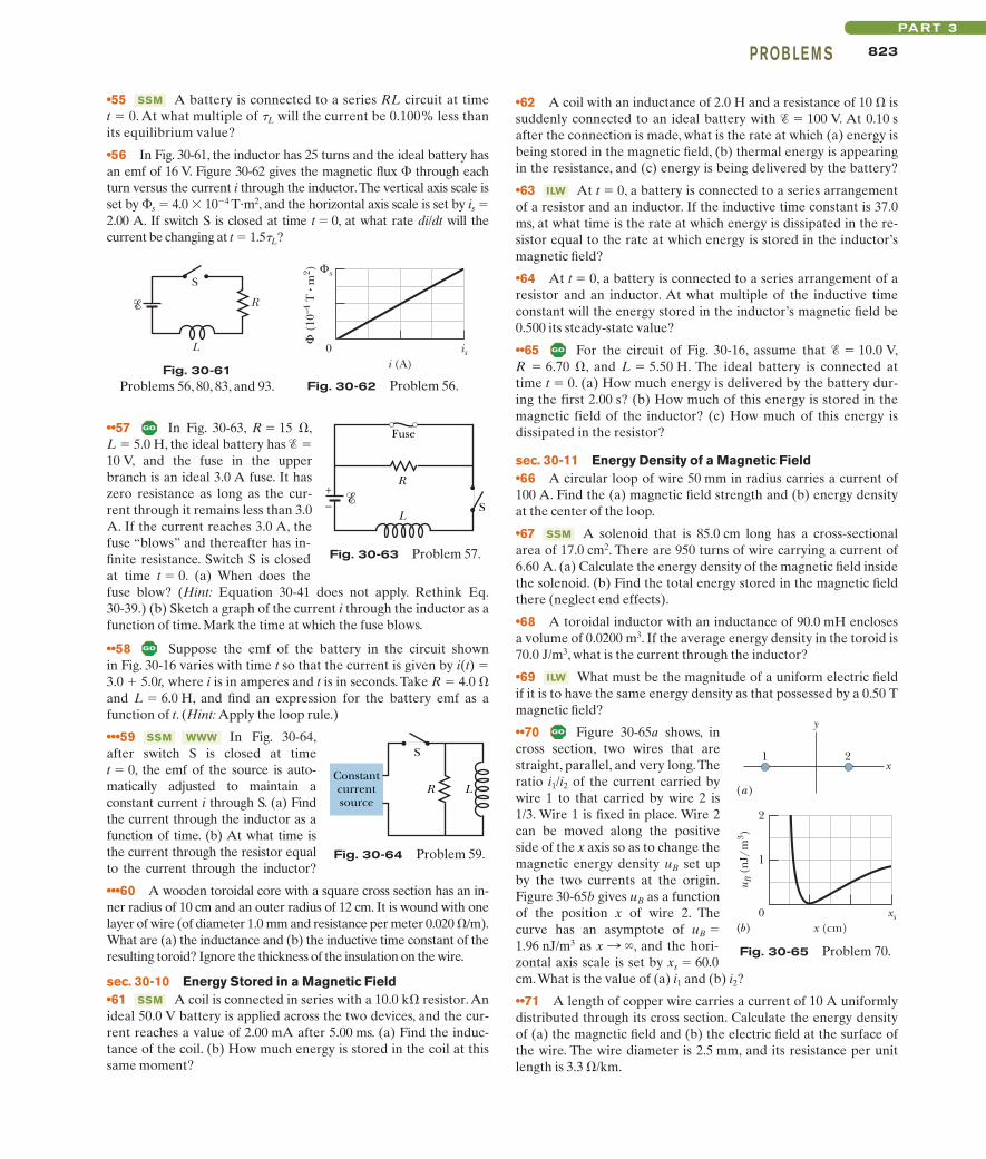
••57 In Fig. 30-63, R � 15 ,L � 5.0 H, the ideal battery has � �10 V, and the fuse in the upperbranch is an ideal 3.0 A fuse. It haszero resistance as long as the cur-rent through it remains less than 3.0A. If the current reaches 3.0 A, thefuse “blows” and thereafter has in-finite resistance. Switch S is closedat time t � 0. (a) When does thefuse blow? (Hint: Equation 30-41 does not apply. Rethink Eq.30-39.) (b) Sketch a graph of the current i through the inductor as afunction of time. Mark the time at which the fuse blows.
••58 Suppose the emf of the battery in the circuit shownin Fig. 30-16 varies with time t so that the current is given by i(t) �3.0 5.0t, where i is in amperes and t is in seconds. Take R � 4.0 and L � 6.0 H, and find an expression for the battery emf as afunction of t. (Hint: Apply the loop rule.)
•••59 In Fig. 30-64,after switch S is closed at time t � 0, the emf of the source is auto-matically adjusted to maintain aconstant current i through S. (a) Findthe current through the inductor as afunction of time. (b) At what time isthe current through the resistor equalto the current through the inductor?
•••60 A wooden toroidal core with a square cross section has an in-ner radius of 10 cm and an outer radius of 12 cm. It is wound with onelayer of wire (of diameter 1.0 mm and resistance per meter 0.020 /m).What are (a) the inductance and (b) the inductive time constant of theresulting toroid? Ignore the thickness of the insulation on the wire.
sec. 30-10 Energy Stored in a Magnetic Field•61 A coil is connected in series with a 10.0 k resistor. Anideal 50.0 V battery is applied across the two devices, and the cur-rent reaches a value of 2.00 mA after 5.00 ms. (a) Find the induc-tance of the coil. (b) How much energy is stored in the coil at thissame moment?
SSM
WWWSSM
823PROB LE M SPART 3
•55 A battery is connected to a series RL circuit at time t � 0. At what multiple of tL will the current be 0.100% less thanits equilibrium value?
•56 In Fig. 30-61, the inductor has 25 turns and the ideal battery hasan emf of 16 V. Figure 30-62 gives the magnetic flux � through eachturn versus the current i through the inductor.The vertical axis scale isset by �s � 4.0 � 10�4 T�m2, and the horizontal axis scale is set by is �2.00 A. If switch S is closed at time t � 0, at what rate di/dt will thecurrent be changing at t � 1.5tL?
SSM •62 A coil with an inductance of 2.0 H and a resistance of 10 issuddenly connected to an ideal battery with � � 100 V. At 0.10 safter the connection is made, what is the rate at which (a) energy isbeing stored in the magnetic field, (b) thermal energy is appearingin the resistance, and (c) energy is being delivered by the battery?
•63 At t � 0, a battery is connected to a series arrangementof a resistor and an inductor. If the inductive time constant is 37.0ms, at what time is the rate at which energy is dissipated in the re-sistor equal to the rate at which energy is stored in the inductor’smagnetic field?
•64 At t � 0, a battery is connected to a series arrangement of aresistor and an inductor. At what multiple of the inductive timeconstant will the energy stored in the inductor’s magnetic field be0.500 its steady-state value?
••65 For the circuit of Fig. 30-16, assume that � � 10.0 V,R � 6.70 , and L � 5.50 H. The ideal battery is connected attime t � 0. (a) How much energy is delivered by the battery dur-ing the first 2.00 s? (b) How much of this energy is stored in themagnetic field of the inductor? (c) How much of this energy isdissipated in the resistor?
sec. 30-11 Energy Density of a Magnetic Field•66 A circular loop of wire 50 mm in radius carries a current of100 A. Find the (a) magnetic field strength and (b) energy densityat the center of the loop.
•67 A solenoid that is 85.0 cm long has a cross-sectionalarea of 17.0 cm2. There are 950 turns of wire carrying a current of6.60 A. (a) Calculate the energy density of the magnetic field insidethe solenoid. (b) Find the total energy stored in the magnetic fieldthere (neglect end effects).
•68 A toroidal inductor with an inductance of 90.0 mH enclosesa volume of 0.0200 m3. If the average energy density in the toroid is70.0 J/m3, what is the current through the inductor?
•69 What must be the magnitude of a uniform electric fieldif it is to have the same energy density as that possessed by a 0.50 Tmagnetic field?
••70 Figure 30-65a shows, incross section, two wires that arestraight, parallel, and very long. Theratio i1/i2 of the current carried bywire 1 to that carried by wire 2 is1/3. Wire 1 is fixed in place. Wire 2can be moved along the positiveside of the x axis so as to change themagnetic energy density uB set upby the two currents at the origin.Figure 30-65b gives uB as a functionof the position x of wire 2. Thecurve has an asymptote of uB �1.96 nJ/m3 as , and the hori-zontal axis scale is set by xs � 60.0cm.What is the value of (a) i1 and (b) i2?
••71 A length of copper wire carries a current of 10 A uniformlydistributed through its cross section. Calculate the energy densityof (a) the magnetic field and (b) the electric field at the surface ofthe wire. The wire diameter is 2.5 mm, and its resistance per unitlength is 3.3 /km.
x : �
ILW
SSM
ILW
Fig. 30-64 Problem 59.
S
Constantcurrentsource
LR
Fig. 30-65 Problem 70.
x
y
1 2
2
1
0x (cm)
xs
u B (
nJ/
m3 )
(a)
(b)
Fig. 30-61Problems 56, 80, 83, and 93.
S
R
L
Fuse
R+– S
L
Fig. 30-63 Problem 57.
Fig. 30-62 Problem 56.
Φ (
10–4
T •
m2 ) Φs
0i (A)
is
halliday_c30_791-825hr.qxd 11-12-2009 12:19 Page 823
Bull
Typewritten Text
** View All Solutions Here **
Bull
Typewritten Text
** View All Solutions Here **

824 CHAPTE R 30 I N DUCTION AN D I N DUCTANCE
sec. 30-12 Mutual Induction•72 Coil 1 has L1 � 25 mH and N1 � 100 turns. Coil 2 has L2 � 40mH and N2 � 200 turns. The coils are fixed in place; their mutual in-ductance M is 3.0 mH. A 6.0 mA current in coil 1 is changing at therate of 4.0 A/s. (a) What magnetic flux �12 links coil 1, and (b) whatself-induced emf appears in that coil? (c) What magnetic flux �21 linkscoil 2,and (d) what mutually induced emf appears in that coil?
•73 Two coils are at fixed locations. When coil 1 has nocurrent and the current in coil 2 increases at the rate 15.0 A/s, theemf in coil 1 is 25.0 mV. (a) What is their mutual inductance? (b)When coil 2 has no current and coil 1 has a current of 3.60 A, whatis the flux linkage in coil 2?
•74 Two solenoids are part of the spark coil of an automobile.When the current in one solenoid falls from 6.0 A to zero in 2.5 ms,an emf of 30 kV is induced in the other solenoid. What is the mu-tual inductance M of the solenoids?
••75 A rectangular loop of Nclosely packed turns is positionednear a long straight wire as shown inFig. 30-66. What is the mutual induc-tance M for the loop–wire combina-tion if N � 100, a � 1.0 cm, b � 8.0cm, and l � 30 cm?
••76 A coil C of N turns is placedaround a long solenoid S of radius Rand n turns per unit length, as in Fig.30-67. (a) Show that the mutual in-ductance for the coil–solenoid com-bination is given by M � m0pR2nN.(b) Explain why M does not dependon the shape, size, or possible lack ofclose packing of the coil.
••77 Two coils connected asshown in Fig. 30-68 separately have inductances L1 and L2. Theirmutual inductance is M. (a) Show that this combination can be re-placed by a single coil of equivalent inductance given by
Leq � L1 L2 2M.
(b) How could the coils in Fig. 30-68 be reconnected to yield anequivalent inductance of
Leq � L1 L2 � 2M?
(This problem is an extension of Problem 47, but the requirementthat the coils be far apart has been removed.)
SSM
ILW
SSM
sistance R. At time t � 0.150 ms, the current through the inductoris changing at the rate of 280 A/s. Evaluate R.
79 In Fig. 30-69, the batteryis ideal and � � 10 V, R1 � 5.0 ,R2 � 10 , and L � 5.0 H. Switch Sis closed at time t � 0. Justafterwards, what are (a) i1, (b) i2, (c)the current iS through the switch, (d)the potential difference V2 acrossresistor 2, (e) the potential differ-ence VL across the inductor, and (f)the rate of change di2/dt? A longtime later, what are (g) i1, (h) i2, (i) iS,( j) V2, (k) VL, and (1) di2/dt?
80 In Fig. 30-61, R � 4.0 k, L � 8.0 mH, and the ideal battery has� � 20 V. How long after switch S is closed is the current 2.0 mA?
81 Figure 30-70a shows arectangular conducting loop of resis-tance R � 0.020 , height H � 1.5cm, and length D � 2.5 cm beingpulled at constant speed v � 40 cm/sthrough two regions of uniform mag-netic field. Figure 30-70b gives thecurrent i induced in the loop as afunction of the position x of the rightside of the loop. The vertical axisscale is set by is � 3.0 mA. For exam-ple, a current equal to is is inducedclockwise as the loop enters region 1.What are the (a) magnitude and (b)direction (into or out of the page) ofthe magnetic field in region 1? What are the (c) magnitude and (d)direction of the magnetic field in region 2?
82 A uniform magnetic field is perpendicular to the plane of acircular wire loop of radius r.The magnitude of the field varies withtime according to B � B0e�t/t, where B0 and t are constants. Findan expression for the emf in the loop as a function of time.
83 Switch S in Fig. 30-61 isclosed at time t � 0, initiating thebuildup of current in the 15.0 mHinductor and the 20.0 resistor.At what time is the emf across theinductor equal to the potentialdifference across the resistor?
84 Figure 30-71a shows twoconcentric circular regions inwhich uniform magnetic fieldscan change. Region 1, with radiusr1 � 1.0 cm, has an outward mag-netic field that is increasing inmagnitude. Region 2, with radiusr2 � 2.0 cm, has an outward mag-netic field that may also bechanging. Imagine that a conduct-ing ring of radius R is centered onthe two regions and then the emf� around the ring is determined.Figure 30-71b gives emf � as a
B:
2
B:
1
B:
SSM
SSM
Fig. 30-68 Problem 77.
ii
ML1
L2
N1 N2
Fig. 30-69 Problem 79.
+–
S
i2
R2
i
R1i1
L
Fig. 30-71 Problem 84.
r1
r2
s
0 2R2 (cm2)
4
(n
V)
(a)
(b)
Fig. 30-67 Problem 76.
C
S
R
Fig. 30-70 Problem 81.
HD
1 2
is
0i (
A)
µ x
(a)
(b)
Fig. 30-66 Problem 75.
N turnsi
l
b
a
Additional Problems78 At time t � 0, a 12.0 V potential difference is suddenly ap-plied to the leads of a coil of inductance 23.0 mH and a certain re-
halliday_c30_791-825hr.qxd 11-12-2009 12:19 Page 824
Bull
Typewritten Text
** View All Solutions Here **
Bull
Typewritten Text
** View All Solutions Here **
87 A square wire loop 20 cm on a side, with resistance20 m, has its plane normal to a uniform magnetic field of magni-tude B � 2.0 T. If you pull two opposite sides of the loop awayfrom each other, the other two sides automatically draw towardeach other, reducing the area enclosed by the loop. If the area is re-duced to zero in time �t � 0.20 s, what are (a) the average emf and(b) the average current induced in the loop during �t?
88 A coil with 150 turns has a magnetic flux of 50.0 nT � m2
through each turn when the current is 2.00 mA. (a) What is theinductance of the coil? What are the (b) inductance and (c) fluxthrough each turn when the current is increased to 4.00 mA?(d) What is the maximum emf � across the coil when the currentthrough it is given by i � (3.00 mA) cos(377t), with t in seconds?
SSM
825PROB LE M SPART 3
function of the square R2 of the ring’s radius, to the outer edge ofregion 2. The vertical axis scale is set by �s � 20.0 nV. What are therates (a) dB1/dt and (b) dB2/dt? (c) Is the magnitude of increas-ing, decreasing, or remaining constant?
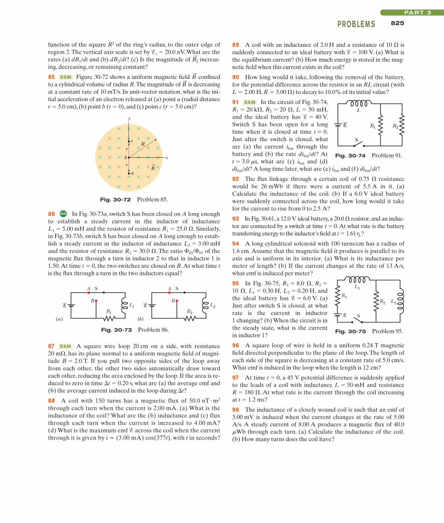
85 Figure 30-72 shows a uniform magnetic field confinedto a cylindrical volume of radius R.The magnitude of is decreasingat a constant rate of 10 mT/s. In unit-vector notation, what is the ini-tial acceleration of an electron released at (a) point a (radial distancer � 5.0 cm), (b) point b (r � 0), and (c) point c (r � 5.0 cm)?
B:
B:
SSM
B:
2
89 A coil with an inductance of 2.0 H and a resistance of 10 issuddenly connected to an ideal battery with � � 100 V. (a) What isthe equilibrium current? (b) How much energy is stored in the mag-netic field when this current exists in the coil?
90 How long would it take, following the removal of the battery,for the potential difference across the resistor in an RL circuit (withL � 2.00 H, R � 3.00 ) to decay to 10.0% of its initial value?
91 In the circuit of Fig. 30-74,R1 � 20 k, R2 � 20 , L � 50 mH,and the ideal battery has � � 40 V.Switch S has been open for a longtime when it is closed at time t � 0.Just after the switch is closed, whatare (a) the current ibat through thebattery and (b) the rate dibat/dt? At t � 3.0 ms, what are (c) ibat and (d) dibat/dt? A long time later, what are (e) ibat and (f) dibat/dt?
92 The flux linkage through a certain coil of 0.75 resistancewould be 26 mWb if there were a current of 5.5 A in it. (a)Calculate the inductance of the coil. (b) If a 6.0 V ideal batterywere suddenly connected across the coil, how long would it takefor the current to rise from 0 to 2.5 A?
93 In Fig. 30-61, a 12.0 V ideal battery, a 20.0 resistor, and an induc-tor are connected by a switch at time t � 0. At what rate is the batterytransferring energy to the inductor’s field at t � 1.61tL?
94 A long cylindrical solenoid with 100 turns/cm has a radius of1.6 cm. Assume that the magnetic field it produces is parallel to itsaxis and is uniform in its interior. (a) What is its inductance permeter of length? (b) If the current changes at the rate of 13 A/s,what emf is induced per meter?
95 In Fig. 30-75, R1 � 8.0 , R2 �10 , L1 � 0.30 H, L2 � 0.20 H, andthe ideal battery has � � 6.0 V. (a)Just after switch S is closed, at whatrate is the current in inductor1 changing? (b) When the circuit is inthe steady state, what is the currentin inductor 1?
96 A square loop of wire is held in a uniform 0.24 T magneticfield directed perpendicular to the plane of the loop. The length ofeach side of the square is decreasing at a constant rate of 5.0 cm/s.What emf is induced in the loop when the length is 12 cm?
97 At time t � 0, a 45 V potential difference is suddenly appliedto the leads of a coil with inductance L � 50 mH and resistance R � 180 . At what rate is the current through the coil increasingat t � 1.2 ms?
98 The inductance of a closely wound coil is such that an emf of3.00 mV is induced when the current changes at the rate of 5.00A/s. A steady current of 8.00 A produces a magnetic flux of 40.0mWb through each turn. (a) Calculate the inductance of the coil.(b) How many turns does the coil have?
SSM
Fig. 30-75 Problem 95.
R1
S
R2 L2
L1
Fig. 30-72 Problem 85.
r
r
Rc
b
aB
y
x
Fig. 30-73 Problem 86.
(a) (b)
A S
BL1
R1
A S
BL2
R2
Fig. 30-74 Problem 91.
R1
S
L
R2
86 In Fig. 30-73a, switch S has been closed on A long enoughto establish a steady current in the inductor of inductance L1 � 5.00 mH and the resistor of resistance R1 � 25.0 . Similarly,in Fig. 30-73b, switch S has been closed on A long enough to estab-lish a steady current in the inductor of inductance L2 � 3.00 mHand the resistor of resistance R2 � 30.0 . The ratio �02/�01 of themagnetic flux through a turn in inductor 2 to that in inductor 1 is1.50.At time t � 0, the two switches are closed on B.At what time tis the flux through a turn in the two inductors equal?
halliday_c30_791-825hr.qxd 11-12-2009 12:19 Page 825
Bull
Typewritten Text
** View All Solutions Here **
Bull
Typewritten Text
** View All Solutions Here **
Related Documents