Chapter 3 Transmission Line and Waveguide 30 I t d ti 3.0 Introduction Transmission Lines are used for low-loss transmission f i of microwave power. Are two conductors required for the transfer of EM wave energy? L. Rayleigh, 1897 TE and TM modes propagation in hollow waveguides with rectangular or circular cross sections. Experiments in 1936: (1) G. C. Southworth at AT&T: Rectangular waveguide. 1 (2) M. L. Barrow at MIT : Circular waveguide. 3.1 General Solutions for TEM, TE, and TM Waves General two conductor Closed waveguide as a General two-conductor transmission line Closed waveguide as a transmission line Assume that all fields have a time–dependence of and j t e propagation factor . EM fields in a waveguide or transmission line are j z e decomposed into longitudinal and transverse components as ˆ (, ,) (, ) (, ) j z t z xyz xy e xy e E E z 2 ˆ (, ,) (, ) (, ) j z t z xyz xy h xy e H H z Field Solution 2 2 2 2 2 2 2 0 0 0 t c t k k k E E E H H H t H H H 0 0 t z t t E j H E E H H t z H H H ˆ ˆ ˆ ˆ ˆ j E H ˆ ˆ ˆ ˆ ˆ ˆ t t z t t z t z t t z E j E j H z j H z E z z E z H z E z 2 2 2 ˆ ˆ 1 t t t t t t t t t t z c t t t z z t z j E k j H j E j H k E E E E z z E 2 c k Similarly, 1 ˆ j H j E H z 3 2 t t z t z c j H j E k H z Field Solution (Cont’d) ˆ ˆ 1 t x y x y In the Cartesian coordinates, 2 1 1 x z z c E j E j H x y k 2 1 1 y z z c E j E j H y x k H j E j H I bi di 2 2 1 x z z c y z z H j E j H y x k H j E j H k 2 In arbitrary coordinates 1 ˆ t t z t z j E j H k E z 2 c x y k 2 1 ˆ c t t z t z k j H j E k H z c k In a cylindrical waveguide, the transversal EM field components can be expressed in terms of E and H the 4 components can be expressed in terms of E z and H z the longitudinal fields.

Welcome message from author
This document is posted to help you gain knowledge. Please leave a comment to let me know what you think about it! Share it to your friends and learn new things together.
Transcript
Chapter 3 Transmission Line and Waveguide
3 0 I t d ti3.0 Introduction Transmission Lines are used for low-loss transmission
f iof microwave power. Are two conductors required for the transfer of EM
wave energy? L. Rayleigh, 1897
TE and TM modes propagation in hollow waveguides with rectangular or circular cross sections.
Experiments in 1936:(1) G. C. Southworth at AT&T: Rectangular waveguide.
1
(2) M. L. Barrow at MIT : Circular waveguide.
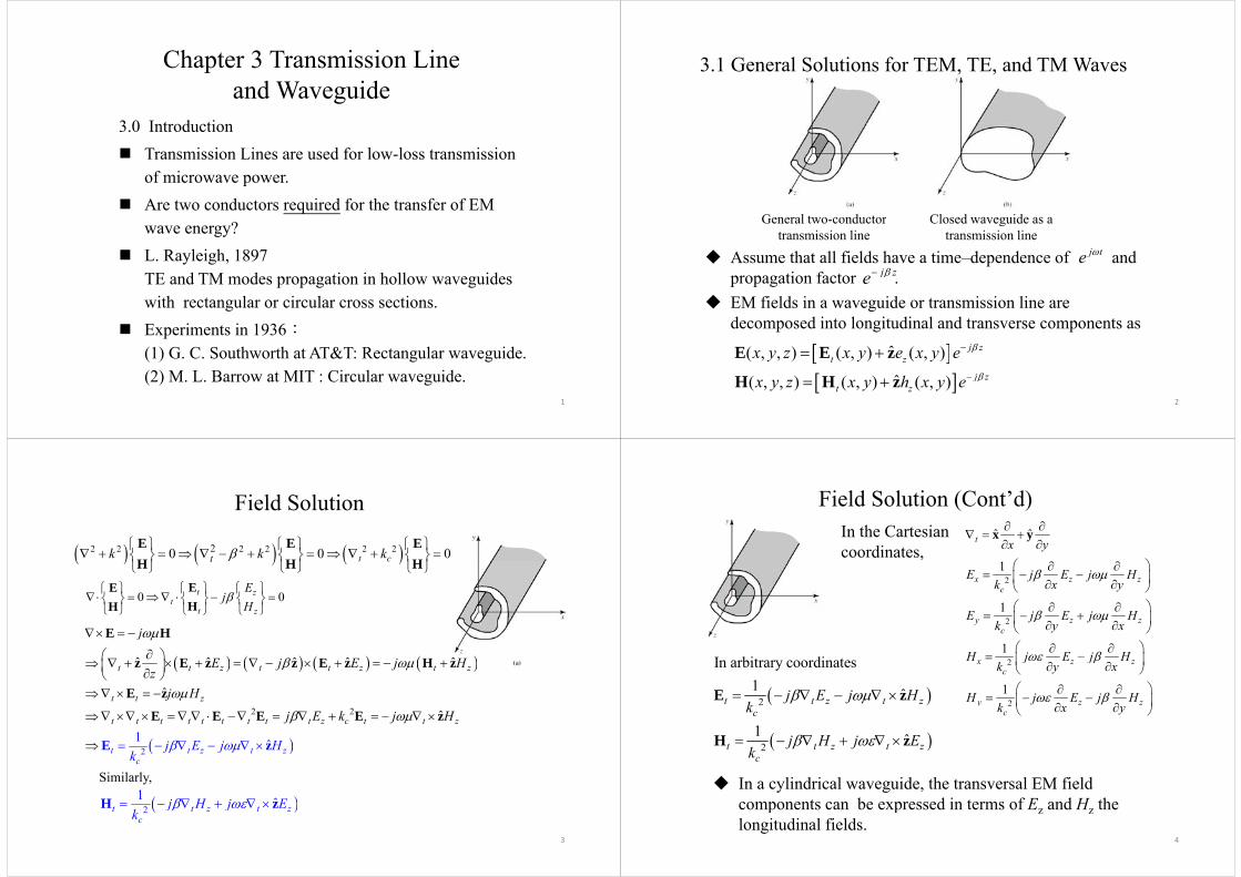
3.1 General Solutions for TEM, TE, and TM Waves
General two conductor Closed waveguide as aGeneral two-conductortransmission line
Closed waveguide as atransmission line
Assume that all fields have a time–dependence of and j te
propagation factor . EM fields in a waveguide or transmission line are
j ze
decomposed into longitudinal and transverse components as
ˆ( , , ) ( , ) ( , ) j zt zx y z x y e x y e E E z
2
ˆ( , , ) ( , ) ( , ) j zt zx y z x y h x y e H H z
Field Solution
2 2 2 2 2 220 0 0t ctk k k
E E EH H H t H H H
0 0t zt
t
Ej
H
EEHH t zH HH
ˆ ˆ ˆ ˆ ˆ
j
E H
ˆ ˆ ˆ ˆ ˆ
ˆ
t t z t t z t z
t t z
E j E j Hz
j H
z E z z E z H z
E z
2 2
2 ˆ
ˆ1
t t t t t
t
t t t t z c t t
t
z
z t z
j E k j H
j E j Hk
E E E E
z
z
E 2ck
Similarly,
1 ˆj H j E H z
3
2t t z t zc
j H j Ek
H z
Field Solution (Cont’d)ˆ ˆ
1
t x y
x yIn the Cartesian coordinates,
21
1
x z zc
E j E j Hx yk
21
1
y z zc
E j E j Hy xk
H j E j H
I bi di 2
21
x z zc
y z z
H j E j Hy xk
H j E j Hk
2
In arbitrary coordinates1 ˆt t z t zj E j H
k E z
2yc x yk
21 ˆ
c
t t z t z
k
j H j Ek
H zck
In a cylindrical waveguide, the transversal EM field components can be expressed in terms of E and H the
4
components can be expressed in terms of Ez and Hz the longitudinal fields.
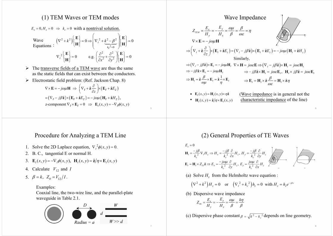
(1) TEM Waves or TEM modes( )
0, 0 0z z cE H k with a nontrival solution.
Wave Equations:
2
2 2 2 2 2
0
0 0t
k
k k
E EH HEquations: 2 0
2 22
2 20 e.g. 0
k
t
c
E EH H2 2x y H H
The transverse fields of a TEM wave are thus the same h i fi ld h i b h d
as the static fields that can exist between the conductors. Electrostatic field problem: (Ref. Jackson Chap. 8)
ˆ ˆ
ˆ ˆ ˆ
t t zj Ez
j E j H
E H z E z
z E z H z
5
,z-component 0 ( , ) ( , )t
t t z t z
t t t
j E j Hx y x y
z E z H zE E
Wave Impedancep
TEMyx EEZ
H H
y xH H
j
E H
ˆ ˆ ˆ ˆ ˆt t z t t z t zE j E j Hz
z E z z E z H z
Similarly
Similarly,
ˆˆ ˆ
t t tj j jj j j j
H E z H Hz H E H z E
ˆˆ
t t t
t t
j jj j
z E Hz E H ,
ˆ ˆ
t t t t
t t t
j j j j
z H E H z E
E H z H z1ˆ ˆ
t t
t t t
j j
z E H
H z E z E
• (Wave impedance is in general not theh i i i d f h li )
ˆ( , ) ( , )t tx y x y E H z• characteristic impedance of the line)
6
ˆ( , ) ( , )t tx y x y H z E
Procedure for Analyzing a TEM Line
1. Solve the 2D Laplace equation,
y g2 ( , ) 0.t x y
2. B. C., tangential E or normal H.3. ˆ( , ) ( , ), ( , ) ( , )t t t tx y x y x y x y E H z E
4. Calculate V12 and I
5 k Z V I 5. 12o, .k Z V I
Examples:Coaxial line, the two-wire line, and the parallel-plate waveguide in Table 2.1.
7
(2) General Properties of TE Waves( ) p0zE
j j j
2 2 2,
ˆ
t t z x z y zc c c
j j jH H H H Hx yk k k
j jZ E H E H
H
E H z 2 2, TEt t x z y zc c
Z E H E Hy xk k
E H z
(a) Solve Hz from the Helmholtz wave equation :
2 2 2 20 or 0 with j zz t c z z zk H k h H h e
( ) z q
yx EE kZ
(b) Dispersive wave impedance
TEy x
ZH H
(c) Dispersive phase constant depends on line geometry2 2k k
8
(c) Dispersive phase constant depends on line geometry. 2 2ck k
(3) General Properties of TM Waves( ) p0zH
j j jE E E E E
E 2 2 2,
ˆ
t t z x z y zc c c
j j jE E E E Ex yk k k
j jH E H E
E
zH E 2 2, TM
t t x z y zc c
H E H EZ y xk k
H E
(a) Solve Ez from the Helmholtz wave equation :
2 2 2 20 or 0 with j zz t c z z zk E k e E e e
(b) Di i i d
TMyx EEZ
H H k
(b) Dispersive wave impedance
(c) Dispersive phase constant depends on line geometry.
TMy xH H k
2 2ck k
9
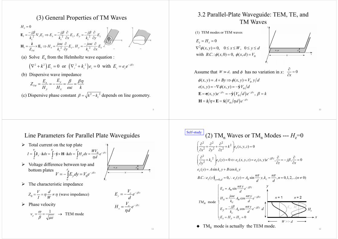
3.2 Parallel-Plate Waveguide: TEM, TE, and TM WTM Waves
(1) TEM modes or TEM waves
2
0
( ) 0 0 0z zE H
W d
( )
2
o
( , ) 0, 0 , 0with . . : ( ,0) 0, ( , )
x y x W y dB C x x d V
Assume that and has no variation in x:,W d f 0Assume that and has no variation in x: ,W d f 0
xo( , ) ( , )
ˆ( ) ( )x y A By x y V y d
V d
y
o
o
( , ) ( , )ˆ( , ) , j z j z
j
e x y x y V dx y e V d e k
yE e y
10
oˆ ˆ j zV d e H z E x
Line Parameters for Parallel Plate Waveguides
0ˆ ˆ ˆW W W
j zWVI d d H d J H
Total current on the top plate
0 0 0
0 j zs xI dx dx H dx e
d
J z y H z
Voltage difference between top and
00
dj z
yV E dy V e
g pbottom plates
0
V d
The characteristic impedance
j zV 0 (wave impedance)V dZ
I W
Phase velocity
j zoy
j zo
VE ed
VH
1 TEM modepv
Phase velocity j zoxH e
d
11
(2) TMn Waves or TMn Modes --- Hz=0Self-study
2 2 22
2 2 2 ( , , ) 0zk e x y zx y z
22
2 ( ) 0 ( , , ) ( , ) , , 0j zc z z zk e y e x y z e x y e j
z xy
0
( ) sin cos
. . : ( ) 0, ( ) sin , , 0,1,2,...( 0)
z c c
z z n cy d
e y A k y B k yn nB C e y e y A y k n nd d
0,( ) , ( ) , , , , , ( )z z n cy dy y yd d
sin j zz n
n yE A ed
cos mode
j zx n
cn
dj n yH A ek dTMj
cos
0
j zn
c
x y z
yj n yE A e
k dE H H
12
x y z
TM0 mode is actually the TEM mode.
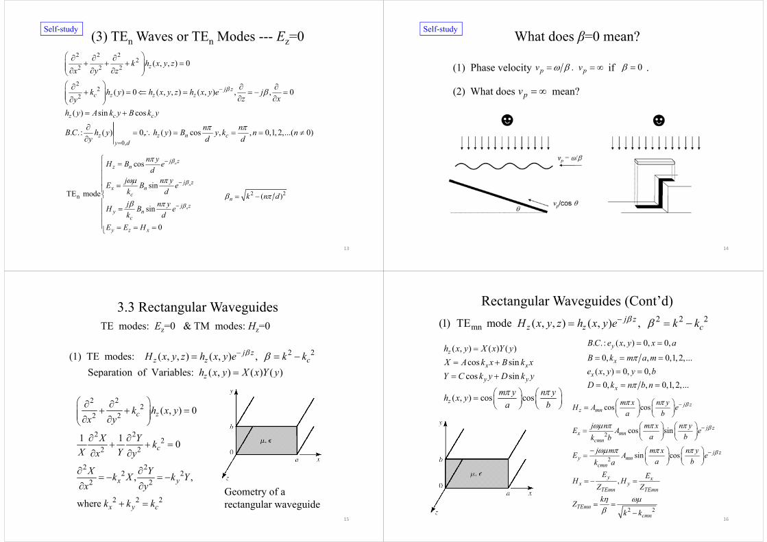
(3) TEn Waves or TEn Modes --- Ez=0Self-study
2 2 22
2 2 2 ( , , ) 0zk h x y zx y z
22
2 ( ) 0 ( , , ) ( , ) , , 0j zc z z zk h y h x y z h x y e j
z xy
( ) sin cos
. . : ( ) 0, ( ) cos , , 0,1, 2,...( 0)
z c c
z z n c
h y A k y B k y
n nB C h y h y B y k n n
cos nj zn yH B e
0,( ) , ( ) , , , , , ( )z z n c
y dy y y
y d d
cos
sinTE mode
n
z n
j zx n
c
H B ed
j n yE B ek d
2 2( )k dnTE mode
sin
0
n
c
j zy n
c
j n yH B ek d
E E H
2 2( )n k n d
13
0y z xE E H
What does β=0 mean?Self-study
(1) Phase velocity if . . p pv v 0
(2) What does mean? pv
14
3.3 Rectangular WaveguidesTE modes: Ez=0 & TM modes: Hz=0
2 2(1) TE modes: ( , , ) ( , ) , Separation of Variables: ( , ) ( ) ( )
j zz z c
z
H x y z h x y e k kh x y X x Y y
p ( , ) ( ) ( )z y y
2 22
22 2
2 2
( , ) 0
1 1
c zk h x yx y
X Y
2 22
2 2
2 2
1 1 0cX Y k
X Yx y
2 22 2
2 2, ,x yX Yk X k Y
x y
Geometry of a
15
2 2 2where x y ck k k y
rectangular waveguide
Rectangular Waveguides (Cont’d)2 2 2j 2 2 2
mn(1) TE mode ( , , ) ( , ) , j zz z cH x y z h x y e k k
( ) ( ) ( )h X Y . . : ( , ) 0, 0,yB C e x y x a ( , ) ( ) ( )cos sincos sin
z
x x
h x y X x Y yX A k x B k xY C k y D k y
( )
0, , 0,1, 2,...( , ) 0, 0,
y
x
x
y
B k m a me x y y b
cos sin
( , ) cos cos
y y
z
Y C k y D k y
m y n yh x ya b
cos cos j zm x n yH A e
0, , 0,1,2,...xD k n b n
a b
2
cos cos
cos sin
jz mn
j zx mn
H A ea b
j n m x n yE A ea bk b
2
2 sin cos
cmn
j zy mn
cmn
a bk bj m m x n yE A e
a bk a
,
cmn
y xx y
TEmn TEmn
E EH HZ Z
16
2 2TEmncmn
kZk k
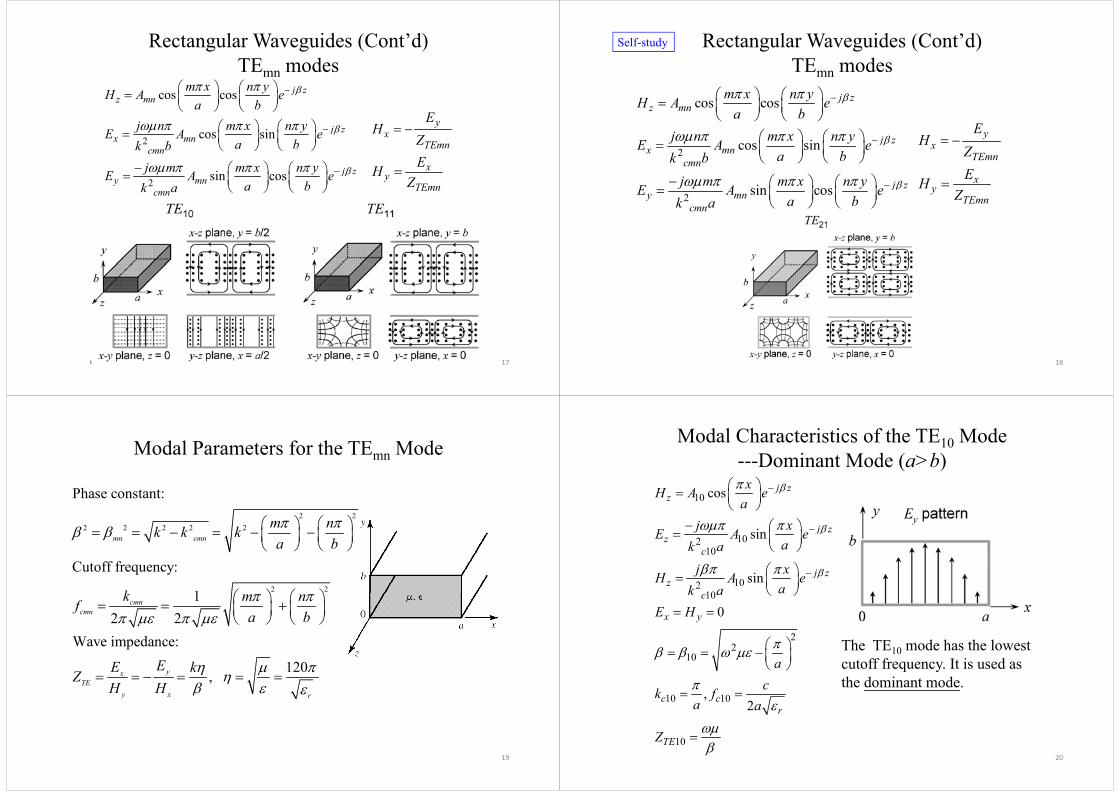
Rectangular Waveguides (Cont’d)TE modesTEmn modes
cos cos j zz mn
m x n yH A ea b
2 cos sin j zx mn
cmn
j n m x n yE A ea bk b
yx
TEmn
EH
Z
2 sin cos j zy mn
cmn
j m m x n yE A ea bk a
xy
TEmn
EHZ
17
Rectangular Waveguides (Cont’d)TE modes
Self-study
TEmn modes
cos cos j zz mn
m x n yH A eb
2 cos sin j zx mn
a bj n m x n yE A e
a bk b
yx
TE
EH
Z
2
2 sin cos
cmn
j zy mn
a bk bj m m x n yE A e
bk
TEmn
xy
TE
ZEH
Z
2y mncmn a bk a
TEmnZ
18
Modal Parameters for the TEmn Mode
Phase constant:2 2
2 2 2 2 2mn cmn
m nk k ka b
2 2
Cutoff frequency:
1k
12 2
W i d
cmncmn
k m nfa b
Wave impedance:
120,yxEE kZ , TE
y x r
ZH H
19
Modal Characteristics of the TE10 Mode---Dominant Mode (a>b)Dominant Mode (a>b)
10 cos j zz
xH A ea
10210
sin j zz
c
aj xE A e
ak a
10
10210
sin
c
j zz
k aj xH A e
ak a
10
2
0c
x y
ak aE H
The TE10 mode has the lowest cutoff frequency. It is used as th d i t d
22
10 a
the dominant mode.10 10,
2c cr
ck fa a
20
10TEZ
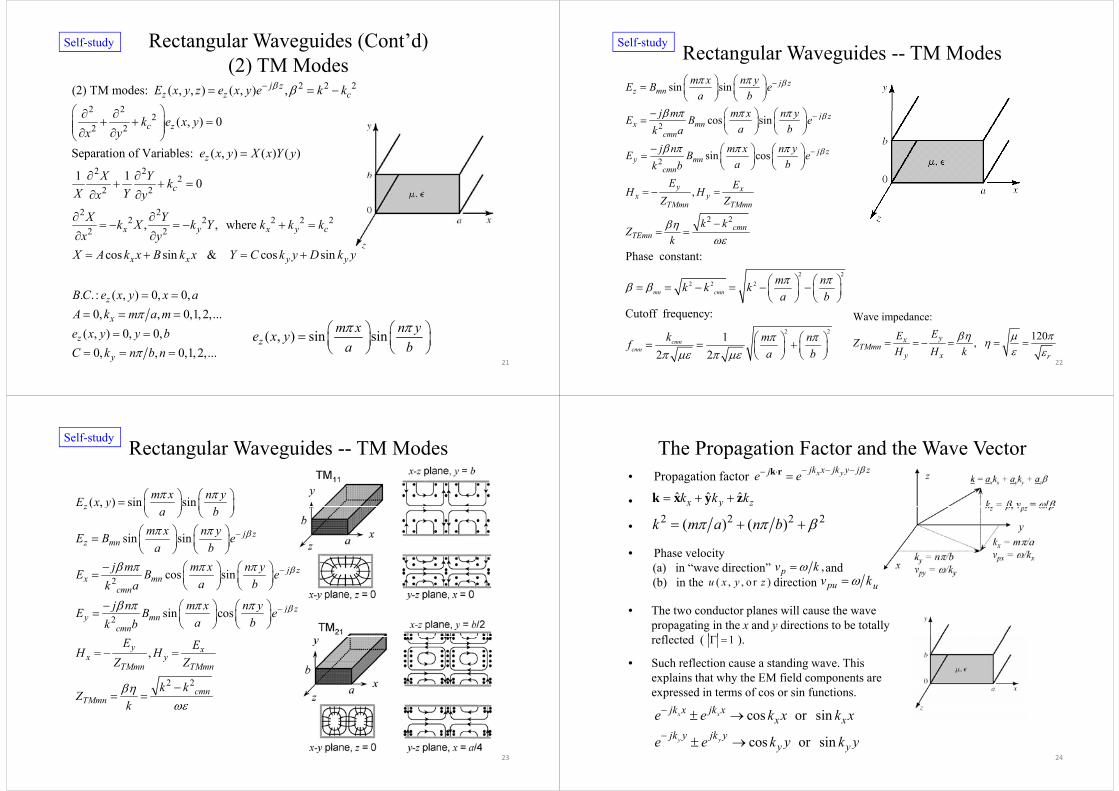
Rectangular Waveguides (Cont’d) (2) TM Modes
Self-study
(2) TM Modes2 2 2
2 2
(2) TM modes: ( , , ) ( , ) ,j zz z cE x y z e x y e k k
2 22
2 2 ( , ) 0
Separation of Variables: ( ) ( ) ( )
c zk e x yx y
e x y X x Y y
2 2
22 2
Separation of Variables: ( , ) ( ) ( )
1 1 0
z
c
e x y X x Y y
X Y kX Yx y
2 2
2 2 2 2 22 2, , where x y x y c
x y
X Yk X k Y k k kx y
cos x
yX A k x B sin & cos sinx y yk x Y C k y D k y
. . : ( , ) 0, 0,0, , 0,1, 2,...
z
x
B C e x y x aA k m a m
m x n y
21
( , ) 0, 0,0, , 0,1, 2,...
z
y
e x y y bC k n b n
( , ) sin sinzm x n ye x y
a b
Rectangular Waveguides -- TM ModesSelf-study
sin sin j zz mn
m x n yE B ea b
j
2 cos sin
sin cos
j zx mn
cmn
j z
j m m x n yE B ea bk a
j n m x n yE B e
2 sin cos
,
jy mn
cmn
y xx y
E B ea bk b
E EH HZ Z
2 2
x yTMmn TMmn
cmnTEmn
Z Z
k kZ
k
k
2 22 2 2
Phase constant:
m nk k k
2 2 2mn cmnk k k
a b
Cutoff frequency: Wave impedance:
22
2 212 2
cmncmn
k m nfa b
120, yxTMmn
y x r
EEZH H k
Rectangular Waveguides -- TM ModesSelf-study
( , ) sin sinzm x n yE x y
( , )
sin sin
z
j zz mn
ya b
m x n yE B ea b
2 cos sin j zx mn
cmn
a bj m m x n yE B e
a bk a
2 sin cos j zy mn
cmn
j n m x n yE B ea bk b
,y xx y
TMmn TMmn
E EH HZ Z
2 2
TMmnk
Zk
2 2
cmnk
23
The Propagation Factor and the Wave Vector• Propagation factor
•
x yjk x jk y j zje e k r
ˆ ˆ ˆx y zk k k k x y z
Ph l it
2 2 2 2( ) ( )k m a n b •
y
• Phase velocity(a) in “wave direction” and(b) in the direction
,pv kpu uv k( , , o r )u x y z
• The two conductor planes will cause the wave propagating in the x and y directions to be totally
fl t d ( )1
• Such reflection cause a standing wave. This explains that why the EM field components are
reflected ( ).1
cos or sinx xjk x jk xx xe e k x k x
explains that why the EM field components are expressed in terms of cos or sin functions.
24
cos or siny y
x xjk y jk y
y ye e k y k y
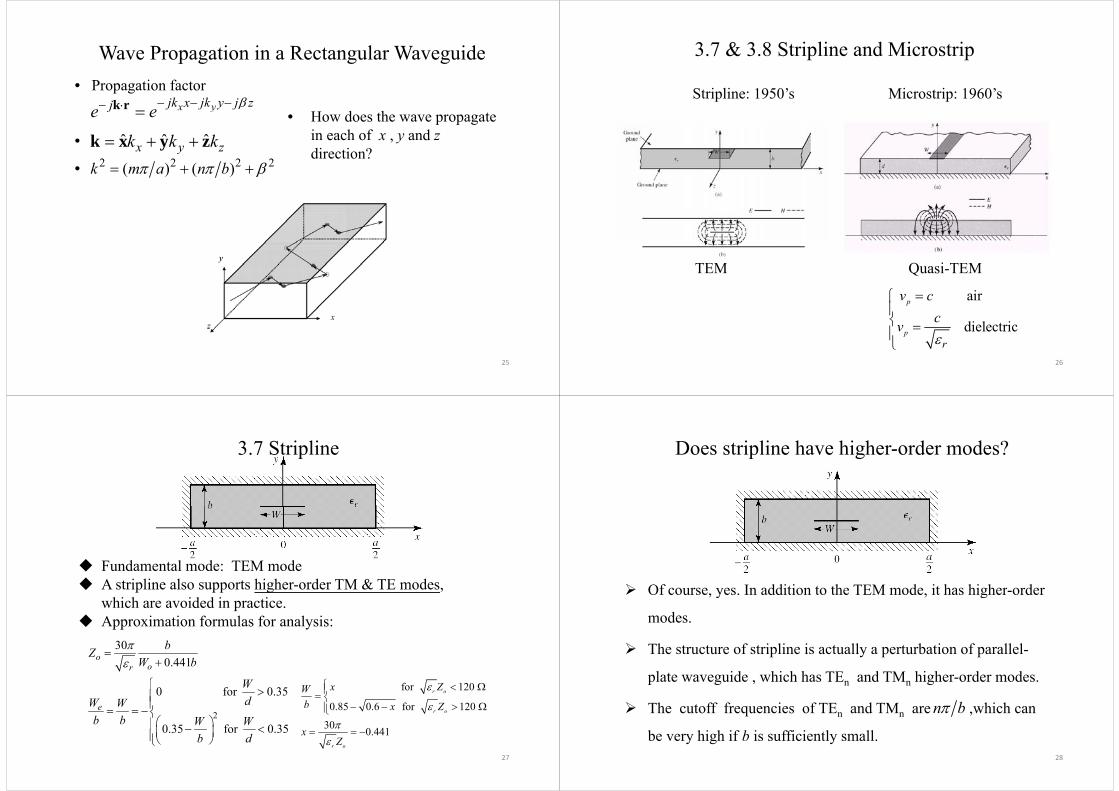
Wave Propagation in a Rectangular Waveguide
x yjk x jk y j zje e k r• Propagation factor
H d hyje e
•• How does the wave propagate
in each of x , y and zdirection?
ˆ ˆ ˆx y zk k k k x y z2 2 2 2( ) ( )k m a n b •
direction?
25
3.7 & 3.8 Stripline and Microstrip
Stripline: 1950’s Microstrip: 1960’s
TEM Quasi-TEM
air
dielectric
pv ccv
26
dielectricpr
v
3.7 Stripline
Fundamental mode: TEM mode A stripline also supports higher-order TM & TE modes,
which are avoided in practice. Approximation formulas for analysis:
300.441o
or
bZW b
W
2
0 for 0.35e
WdW W
b b W W
for 120
0.85 0.6 for 120
30
r o
r o
x ZWb x Z
27
0.35 for 0.35b b W W
b d
30 0.441r o
xZ
Does stripline have higher-order modes?
Of course, yes In addition to the TEM mode, it has higher-order Of course, yes. In addition to the TEM mode, it has higher order
modes.
The structure of stripline is actually a perturbation of parallel-
plate waveguide which has TE and TM higher-order modesplate waveguide , which has TEn and TMn higher order modes.
The cutoff frequencies of TEn and TMn are ,which can n b
28
be very high if b is sufficiently small.
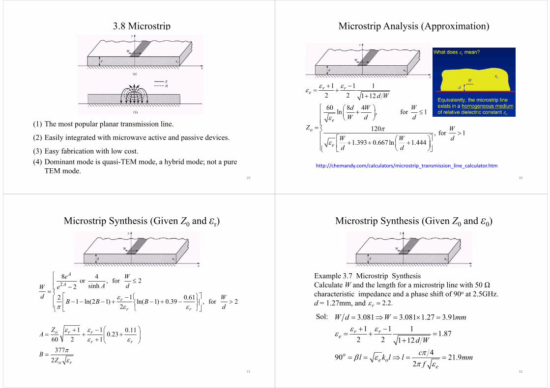
3.8 Microstrip
(1) The most popular planar transmission line.
(2) Easily integrated with microwave active and passive devices.(2) Easily integrated with microwave active and passive devices.
(3) Easy fabrication with low cost.(4) Dominant mode is quasi TEM mode a hybrid mode; not a pure
29
(4) Dominant mode is quasi-TEM mode, a hybrid mode; not a pure TEM mode.
Microstrip Analysis (Approximation)
1 1 12 2 1 12
r re d W
2 2 1 12
60 8 4ln , for 1
d W
d W WW d d
120 , for 1
e
o
W d dZ W
dW W
1.393 0.667 ln 1.444e
dW Wd d
30
http://chemandy.com/calculators/microstrip_transmission_line_calculator.htm
Microstrip Synthesis (Given Z0 and εr)
28 4 or , for 2
sinh2
A
Ae W
A deW
12 0.611 ln(2 1) ln( 1) 0.39 , for 2
2r
r r
d WB B Bd
1 1 0.110 23o r rZA
0.23
60 2 1377
o r r
r rA
B
31
2 o rB
Z
Microstrip Synthesis (Given Z0 and ε0)
Example 3.7 Microstrip Synthesis Calculate W and the length for a microstrip line with 50 Ωcharacteristic impedance and a phase shift of 90o at 2.5GHz. d = 1.27mm, and 2.2.r
3.081 3.081 1.27 3.911 1 1 1 87r r
W d W mm
Sol:
1.872 2 1 12
490 21 9
e
o
d Wcl k l l
32
490 21.92
oe o
e
cl k l l mmf
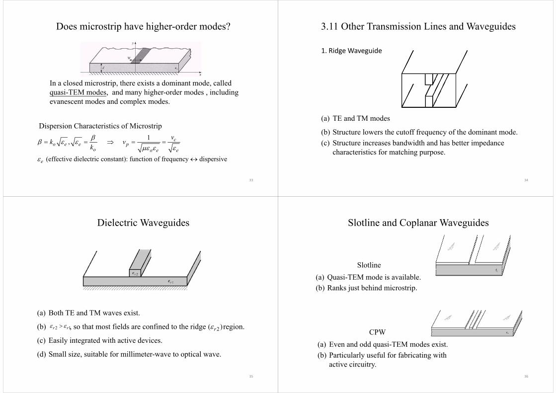
Does microstrip have higher-order modes?
In a closed microstrip, there exists a dominant mode, called quasi-TEM modes, and many higher-order modes , including evanescent modes and complex modes.
Dispersion Characteristics of Microstrip1 cv
k v ,
(effective dielectric constant): function of frequency dispersive
o e e po o e e
e
k vk
33
3.11 Other Transmission Lines and Waveguides
1. Ridge Waveguide
(a) TE and TM modes(a) TE and TM modes
(b) Structure lowers the cutoff frequency of the dominant mode.( ) St t i b d idth d h b tt i d(c) Structure increases bandwidth and has better impedance
characteristics for matching purpose.
34
Dielectric Waveguides
(a) Both TE and TM waves exist.( )
(b) , so that most fields are confined to the ridge region.
( ) E il i d i h i d i
2 1r r 2( )r
(c) Easily integrated with active devices.
(d) Small size, suitable for millimeter-wave to optical wave.
35
Slotline and Coplanar Waveguides
Slotline(a) Quasi-TEM mode is available.(b) Ranks just behind microstrip.
CPW(a) Even and odd quasi-TEM modes exist.(b) Particularly useful for fabricating with
36
active circuitry.

Table 3.6Comparison of Common Transmission Lines and Waveguides
Characteristic Coax Waveguide Stripline MicrostripModes: Preferred TEM TEM Quasi-TEM
Other TM TE TM TE TM TE Hybrid TM TE10TE
Other TM,TE TM,TE TM,TE Hybrid TM,TE Dispersion None Medium None LowBandwidth High Low High Highdw d g ow g gLoss Medium Low High HighPower capacity Medium High Low LowPhysical size Large Large Medium SmallEase of Medium Medium Easy EasyfabricationfabricationIntegration Hard Hard Fair Easy
37
3.3 Circulator Waveguides
Determining the longitudinal components Ez and Bz, we could quickly calculate all the others.
2 2 ( )( / )
z zx
E BiE kc k x y
E Bi
2 2 ( )( / )
z zy
E BiE kc k y x
B Ei
2 2 2( )( / )
z zx
B EiB kc k x c y
B Ei
2 2 2( )( / )
z zy
B EiB kc k y c y
2 2 22
2 2 2
2 2 2
0zk Ex y v
If 0 TE (transverse electric) waves;If 0 TM (transverse magnetic) waves;
z
z
EB
38
2 2 22
2 2 2 0zk Bx y v
( g ) ;If 0 and 0 TEM waves.
z
z zE B
TM Mode of a Waveguide (B = 0):
TE and TM modes
2 2( ) 0 with boundary condition 0 t z z sE Eik
TM Mode of a Waveguide (Bz = 0):
2
1
zt t z
ik E
E
Assume perfectlyconducting wall.1 t z t z t
z ek Z
H e E e E
2 2 2
k
, wave impedanceof TM modes
e zZ k zk
2 2
TE Mode of a Waveguide (Ez = 0):
of TM modes
2 2( ) 0 with boundary condition 0 t z zn sz
H Hik H
H
, wave impedance of TE modes
h zZ k b .c . 0s n H
2 t t z
t z t h z t
H
Z
H
E e H e H
impedance of TE modes0
00
s
z t s
t z sHH
n e n Hn
2 2 2
t z t h z tz
z
Zk
k
E e H e H
39
0z sn H
Table 3.5Circular
nm nmx x
Circular Waveguide
40

The Roots of Bessel Function (TMnm modes)
m=1 2.4048 3.8317 5.1356 6.3802 7.5883 8.7715
nmx 0 0( )mJ x 1 1( )mJ x 2 2( )mJ x 3 3( )mJ x 4 4( )mJ x 5 5( )mJ x
2 5.5201 7.0156 8.4172 9.7610 11.0647 12.33863 8.6537 10.1735 11.6198 13.0152 14.3725 15.70024 11 7915 13 3237 14 7960 16 2235 17 6160 18 98014 11.7915 13.3237 14.7960 16.2235 17.6160 18.98015 14.9309 16.4706 17.9598 19.4094 20.8269 22.2178
0( )J x1( )J x
2 ( )J x( )J x3( )J x
4 ( )J x5( )J x
41
The Roots of Bessel Derivative (TEnm modes)
m=1 3.8317 1.8412 3.0542 4.2012 5.3175 6.4156nmx 0 0( )mJ x 1 1( )mJ x 2 2( )mJ x 3 3( )mJ x 4 4( )mJ x 5 5( )mJ x
2 7.0156 5.3314 6.7061 8.0152 9.2824 10.51993 10.1735 8.5363 9.9695 11.3459 12.6819 13.98724 13 3237 11 7060 13 1704 14 5858 15 9641 17 31284 13.3237 11.7060 13.1704 14.5858 15.9641 17.31285 16.4706 14.8636 16.3475 17.7887 19.1960 20.5755
( )J x1( )J x
2 ( )J x3( )J x
4 ( )J x ( )J x4 ( )5( )J x
420( )J x
Normalized Cutoff Frequency and Attenuation
43
Field Patterns and Surface Current of Circular Waveguide Modes
Coaxial TEM
of Circular Waveguide Modes
surface currentE-field
44
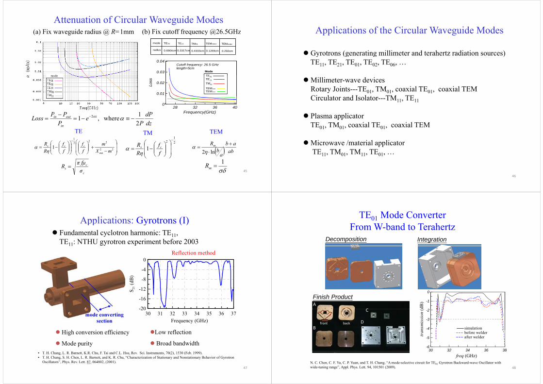
Attenuation of Circular Waveguide Modes (a) Fix waveguide radius @ R=1mm (b) Fix cutoff frequency @26 5GHz
radius
TE01 TE11
0.6904cm 0.3317cm
TM01 TEMinner TEMouter
0.1269cm 0.292cm0.4333cm
mode
(a) Fix waveguide radius @ R 1mm (b) Fix cutoff frequency @26.5GHz
0.03
0.04
TEMode
Cutoff frequency: 26.5 GHzlength=5cm
0.01
0.02
Loss
TE01 TE11 TM01
TEMouter
TEMinner
28 32 36 40Frequency(GHz)
0
dPPPL zoutin 1h1 2
1 1TE TM TEM
dzPe
PLoss z
in
outin
2 where,1 2
22
2221
1mX
mff
ff
RηR
mn
ccs21
2
1
ff
RηR cs ab
ab
ab
Rm
ln2
c
cs σ
π fμR 1
mR45
Applications of the Circular Waveguide ModesApplications of the Circular Waveguide Modes
Gyrotrons (generating millimeter and terahertz radiation sources) Gyrotrons (generating millimeter and terahertz radiation sources)TE11, TE21, TE01, TE02, TE06, …
Millimeter-wave devicesRotary Joints---TE01, TM01, coaxial TE01, coaxial TEMCi l t d I l t TM TECirculator and Isolator---TM11, TE11
Plasma applicator Plasma applicatorTE01, TM01, coaxial TE01, coaxial TEM
Microwave /material applicatorTE11, TM01, TM11, TE01, …
46
Applications: Gyrotrons (I)pp y ( ) Fundamental cyclotron harmonic: TE11,
TE11: NTHU gyrotron experiment before 2003
0Reflection method
12
-8
-4
21 (d
B)
-20
-16
-12S 2
Hi h i ffi i
30 31 32 33 34 35 36 37Frequency (GHz)
-20
L fl i High conversion efficiency
Mode purity
Low reflection
Broad bandwidth
47
• T. H. Chang, L. R. Barnett, K.R. Chu, F. Tai and C.L. Hsu, Rev. Sci. Instruments, 70(2), 1530 (Feb. 1999).• T. H. Chang, S. H. Chen, L. R. Barnett, and K. R. Chu, “Characterization of Stationary and Nonstationary Behavior of Gyrotron
Oscillators”, Phys. Rev. Lett. 87, 064802, (2001).
TE01 Mode Converter F W b d t T h t
Decomposition Integration
From W-band to Terahertz
2
-1
0
dB)
Finish ProductA
C
-4
-3
-2
nsm
issi
on (
simulationfront back
B
C
D
30 32 34 36 38-6
-5tran before welder
after welder
30 32 34 36 38freq (GHz)
N. C. Chen, C. F. Yu, C. P. Yuan, and T. H. Chang, “A mode-selective circuit for TE01 Gyrotron Backward-wave Oscillator with wide-tuning range”, Appl. Phys. Lett. 94, 101501 (2009). 48
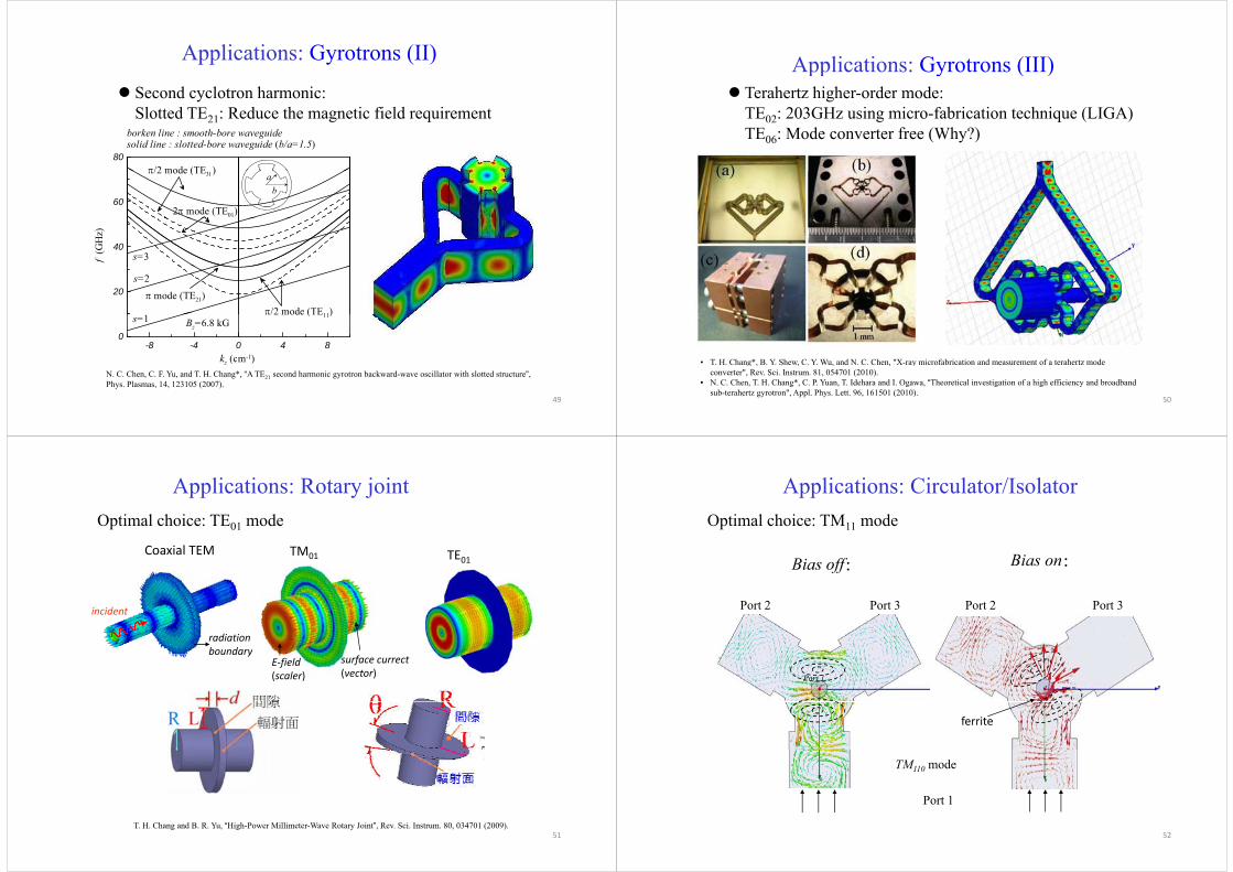
Applications: Gyrotrons (II)
Second cyclotron harmonic: Slotted TE21: Reduce the magnetic field requirement
80
borken line : smooth-bore waveguidesolid line : slotted-bore waveguide (b/a=1.5)
/2 mode ( )
602 mode (TE01)
/2 mode () ab
40
f (G
Hz)
s=3
20 mode (TE21)/2 mode (TE11)
s=2
-8 -4 0 4 8kz (cm-1)
0Bz=6.8 kG
/2 mode (TE11)s=1
49
kz (cm )N. C. Chen, C. F. Yu, and T. H. Chang*, “A TE21 second harmonic gyrotron backward-wave oscillator with slotted structure”, Phys. Plasmas, 14, 123105 (2007).
Applications: Gyrotrons (III)pp y ( ) Terahertz higher-order mode:
TE02: 203GHz using micro-fabrication technique (LIGA)TE06: Mode converter free (Why?)
• T H Chang* B Y Shew C Y Wu and N C Chen "X ray microfabrication and measurement of a terahertz mode
50
• T. H. Chang*, B. Y. Shew, C. Y. Wu, and N. C. Chen, X-ray microfabrication and measurement of a terahertz mode converter", Rev. Sci. Instrum. 81, 054701 (2010).
• N. C. Chen, T. H. Chang*, C. P. Yuan, T. Idehara and I. Ogawa, “Theoretical investigation of a high efficiency and broadband sub-terahertz gyrotron", Appl. Phys. Lett. 96, 161501 (2010).
Applications: Rotary jointOptimal choice: TE01 mode
TE01TM01Coaxial TEM TE0101
incident
radiation boundary
E‐field(scaler)
surface currect(vector)
boundary
51T. H. Chang and B. R. Yu, “High-Power Millimeter-Wave Rotary Joint”, Rev. Sci. Instrum. 80, 034701 (2009).
Applications: Circulator/IsolatorOptimal choice: TM11 mode
B ff Bias on:
Port 2 Port 3
Bias off:
Port 2 Port 3
Bias on:
Port 2 Port 3 Port 2 Port 3
Port 1
ferrite
P t 1
TM110 mode
52
Port 1

Plasma applicator: TE11, TM040, TE031s pp c o : 11, 040, 031
TM040
Novel distributive type:Novel distributive type:2 × 2 circular polarized TE11
TE031TE031
53NTHU Patent pending
Microwave /material applicator Example: TMExample: TM110
microwave source2.45 GHz, 3 kW,
IR temperaturesensor
resonant frequencyadjustable
54
NTHU US Patentviewing port
The End of Chap. 3 f p
55
Related Documents


![Terahertz electromagnetic crystal waveguide fabricated by ...€¦ · [5], metal wire [6, 7], coaxial transmission line [8], sub-wavelength fiber [2, 9–11], photonic crystal fiber](https://static.cupdf.com/doc/110x72/5fc79678232a637257064bbe/terahertz-electromagnetic-crystal-waveguide-fabricated-by-5-metal-wire-6.jpg)