Chapter 3 Project description

Welcome message from author
This document is posted to help you gain knowledge. Please leave a comment to let me know what you think about it! Share it to your friends and learn new things together.
Transcript
Chapter 3 Project description

Chapter 3: Project Description
ERA: Proposed Ranger 3 Deeps Underground Mine 3-i
CONTENTS
3.1 INTRODUCTION 3-1
3.2 SETTING AND FOOTPRINT 3-2
3.3 RANGER 3 DEEPS UNDERGROUND MINE 3-4
3.3.1 The Ranger 3 Deeps Uranium Deposit 3-4
3.3.2 Exploration and Drilling 3-6
3.3.3 Mine Design 3-9
3.3.3.1 Mine Access 3-9
3.3.3.2 Mining Method and Sequence 3-9
3.3.3.3 Backfill Method 3-12
3.3.3.4 Dimensions and Gradients 3-14
3.3.3.5 Mine Ventilation 3-14
3.3.4 Plant and Machinery 3-16
3.3.5 Annual Production Volumes 3-16
3.4 PROCESSING 3-17
3.4.1 Processing Methods 3-17
3.4.2 Consumables 3-20
3.4.3 Product 3-20
3.5 NEW INFRASTRUCTURE 3-21
3.5.1 Backfill Plant and Tailings Dewatering Plant 3-23
3.5.1.1 Maintenance Requirements 3-27
3.5.2 Refrigerated Air and Ventilation System 3-27
3.5.2.1 Mechanical and Operational Characteristics 3-28
3.5.2.2 Noise Considerations 3-31
3.5.2.3 Maintenance Requirements 3-32
3.5.2.4 Ventilation Shaft Construction Methods and Sequence 3-32
3.5.3 Power Plant 3-35
3.5.3.1 Mechanical and Operational Characteristics 3-37
3.5.3.2 Fuel Consumption and Emissions 3-38
3.5.3.3 Energy Efficiency 3-40
3.5.3.4 Maintenance Requirements 3-41
3.5.3.5 Construction Sequence 3-41
3.5.4 Mine Dewatering Facilities 3-41
3.5.4.1 Mechanical and Operational Characteristics 3-42
3.5.4.2 Maintenance Requirements 3-43
3.5.5 Supporting Infrastructure 3-43
3.5.5.1 Diesel Supply and Storage 3-44
3.5.5.2 Water Supply 3-45
3.5.5.3 Compressed Air 3-46
3.5.5.4 Reticulation of Materials and Power 3-47
3.5.5.5 Explosives Storage 3-47
3.5.5.6 Shotcrete Transfer Station 3-48
3.5.5.7 Office Complex 3-49

Chapter 3: Project Description
ERA: Proposed Ranger 3 Deeps Underground Mine 3-ii
3.5.5.8 Roads 3-49
3.5.5.9 Secondary Egress 3-50
3.5.5.10 Plant Lighting 3-51
3.5.5.11 Communications 3-51
3.5.6 Construction 3-51
3.6 TRANSPORT 3-52
3.6.1 Primary Corridors 3-52
3.6.2 Access Tracks 3-52
3.7 WATER MANAGEMENT 3-52
3.7.1 Process Water 3-54
3.7.2 Pond Water 3-54
3.7.2.1 Fire Water System 3-54
3.7.2.2 Drilling and Dust Suppression 3-54
3.7.2.3 Backfill Production 3-54
3.7.3 Potable Water 3-55
3.7.4 Managed Release water 3-55
3.7.5 Waste Water and Sewerage 3-55
3.8 WASTE MANAGEMENT 3-56
3.8.1 Mineralised Waste 3-56
3.8.2 Non-mineralised Waste 3-56
3.9 PROJECT SCHEDULE AND WORKFORCE 3-59
3.9.1 Project Schedule 3-59
3.9.2 Workforce 3-60
3.9.3 Accommodation Requirements 3-62
3.10 CLOSURE AND REHABILITATION 3-63
3.10.1 Final Landform Design 3-63
3.10.2 Infrastructure Decommissioning 3-64
3.10.3 Rehabilitation Techniques and Revegetation Program 3-64
3.10.4 Solute Transport from Tailings and Waste Rock 3-65
3.10.5 Post Closure Monitoring 3-65
3.10.6 Staging and Timing 3-65
FIGURES
Figure 3-1: Provisional mining layout 3-2
Figure 3-2: Indicative footprint of the proposed surface infrastructure 3-3
Figure 3-3: Regional geology within the location of the Ranger 3 Deeps uranium deposit 3-5
Figure 3-4: Typical west-east cross-section of the Ranger 3 Deeps deposit 3-6
Figure 3-5: Location of the Ranger 3 Deeps resource, exploration decline and drilling fans 3-7
Figure 3-6: Typical cross section showing drilling intersecting two styles of mineralisation 3-8
Figure 3-7: Existing underground facilities showing exploration decline and exhaust 3-9
Figure 3-8: Diagrammatic representation of the transverse open stoping method 3-10
Figure 3-9: View of proposed underground mine, looking south-west 3-11
Figure 3-10: Indicative stope mining sequences 3-12

Chapter 3: Project Description
ERA: Proposed Ranger 3 Deeps Underground Mine 3-iii
Figure 3-11: Indicative paste reticulation design 3-13
Figure 3-12: Ventilation schematic showing indicative locations of airways 3-15
Figure 3-13: Mine ventilation during long-hole drilling of a secondary stope 3-15
Figure 3-14: Mineral abundance of 2013 leach feed and Ranger 3 Deeps composite samples 3-18
Figure 3-15: Existing processing circuit with high carbonate ore pathway 3-19
Figure 3-16: Indicative location of the proposed infrastructure for the Project 3-22
Figure 3-17: Indicative image of the backfill plant and tailings dewatering plant 3-24
Figure 3-18: Schematic flow diagram of the tailings dewatering plant and backfill plant 3-25
Figure 3-19: Schematic flow diagram of the mine ventilation system 3-27
Figure 3-20: Indicative image of a typical fresh air intake 3-29
Figure 3-21: Indicative image of a typical exhaust fan installation 3-30
Figure 3-22: Ventilation shaft slab showing completed pile driving 3-33
Figure 3-23: An example of a shaft pre-sink with raise bore pilot rod stabilisers 3-34
Figure 3-24: Planned location of the Project power plant 3-35
Figure 3-25: Indicative image of the Project power plant 3-36
Figure 3-26: Schematic flow diagram of the Project power plant and major electrical infrastructure 3-36
Figure 3-27: Schematic flow diagram of the mine dewatering system 3-42
Figure 3-28: Indicative image of the silt traps, settling ponds and oil/water separators 3-43
Figure 3-29: Indicative image of the diesel refuelling station 3-44
Figure 3-30: Schematic flow diagram of the potable and pond water systems 3-46
Figure 3-31: Indicative image of the air compressor and surface air accumulator 3-46
Figure 3-32: Indicative image of the office complex 3-49
Figure 3-33: A typical egress hoist system 3-50
Figure 3-34: Typical Project water balance 3-53
Figure 3-35: Indicative materials balance for Ranger 3 Deeps underground mine 3-57
Figure 3-36: Waste classification – existing operations and the Project 3-58
Figure 3-37: Indicative Ranger 3 Deeps development schedule 3-59
Figure 3-38: Combined workforce – Ranger 3 Deeps and existing operations 3-62
Figure 3-39: Combined (existing and Project) workforce accommodation 3-63
TABLES
Table 3-1: Ranger 3 Deeps measured, indicated and inferred resources (20 June 2014) 3-8
Table 3-2: Backfill delivery rates 3-13
Table 3-3: Lateral development dimensions 3-14
Table 3-4: Indicative size of the mobile underground equipment fleet 3-16
Table 3-5: Indicative Ranger 3 Deeps ore production schedule 3-17
Table 3-6: Forecast annual consumables for the Project 3-20
Table 3-7: Exhaust fan noise levels 3-31
Table 3-8: Typical unattenuated fan sound pressure levels (dBA) 3-31
Table 3-9: Refrigeration unit noise levels at 100% load 3-32
Table 3-10: Mine ventilation equipment installation sequence 3-34
Table 3-11: Power generator: exhaust emissions (one unit) 3-39
Table 3-12: Average yearly power demand and associated diesel consumption 3-40
Table 3-13: Power plant equipment installation sequence 3-41
Table 3-14: Ranger 3 Deeps underground employees 3-61
Table 3-15: Workforce requirements – Project and existing operations 3-61

Chapter 3: Project Description
ERA: Proposed Ranger 3 Deeps Underground Mine 3-1
3 PROJECT DESCRIPTION
3.1 INTRODUCTION
Chapter 3 provides a comprehensive description of the Ranger 3 Deeps underground mine
(the Project) and associated infrastructure, and includes details of design criteria, operations
and decommissioning strategies. Specific attention has been paid to minimising the Project's
footprint and maximising use of the existing mine infrastructure described in Chapter 2.
The Project will mine an underground uranium ore body east of Pit 3, with most mining
activity occurring between 200 and 500 m below the surface. Mining will remove
approximately 6.8 Mt of uranium ore, at an average grade of 0.27% U3O8, plus 0.6 Mt of low
grade ore and 0.5 Mt of waste rock before completion of operations in January 2021. This
represents approximately 50% of the overall resource, currently estimated to contain more
than 32,000 tonnes of uranium oxide.1
The existing portal and exploration decline will provide the sole vehicular access into the
underground mine. The exploration decline, approved in 2011, was constructed to determine
if underground mining was economically feasible.
Ore will be transported to the surface using diesel trucks and ore processing will take place
using the existing processing facilities at the Ranger mine. As ore is removed from stopes,
the underground mine will be progressively backfilled and sealed with a paste, typically
comprising tailings, crushed low-grade rock2 and cement binder. The paste will be pumped,
or gravity fed, from the surface via cased boreholes.
Underground mining operations will be supported by the existing surface facilities and the
following new infrastructure:
� backfill plant and tailings dewatering plant;
� mine ventilation and refrigeration infrastructure;
� additional diesel power generation units;
� mine dewatering facilities; and
� roads and supporting infrastructure.
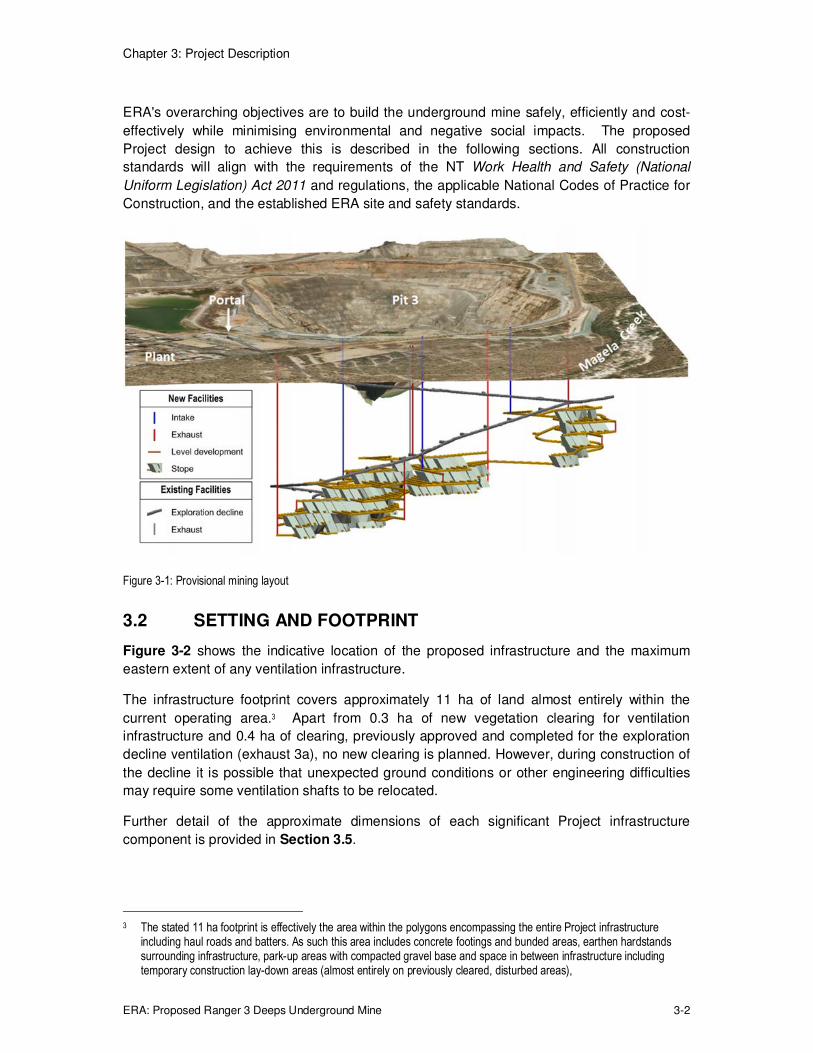
The location of the ore body in relation to the exploration decline, the provisional mine layout
and Pit 3 are shown in Figure 3-1.
1 Normal practice in mining is to extract that portion of the total resource which is economic (i.e. based on considerations
of grade, mining, processing and capital costs). Ranger 3 Deeps will not generate 32,000 tonnes of saleable product.
2 Category 2 rock containing 0.02 – 0.05 wt% of U3O8. The term "low grade rock" is used interchangeably with "low grade ore".
Chapter 3: Project Description
ERA: Proposed Ranger 3 Deeps Underground Mine 3-2
ERA's overarching objectives are to build the underground mine safely, efficiently and cost-
effectively while minimising environmental and negative social impacts. The proposed
Project design to achieve this is described in the following sections. All construction
standards will align with the requirements of the NT Work Health and Safety (National
Uniform Legislation) Act 2011 and regulations, the applicable National Codes of Practice for
Construction, and the established ERA site and safety standards.
Figure 3-1: Provisional mining layout
3.2 SETTING AND FOOTPRINT
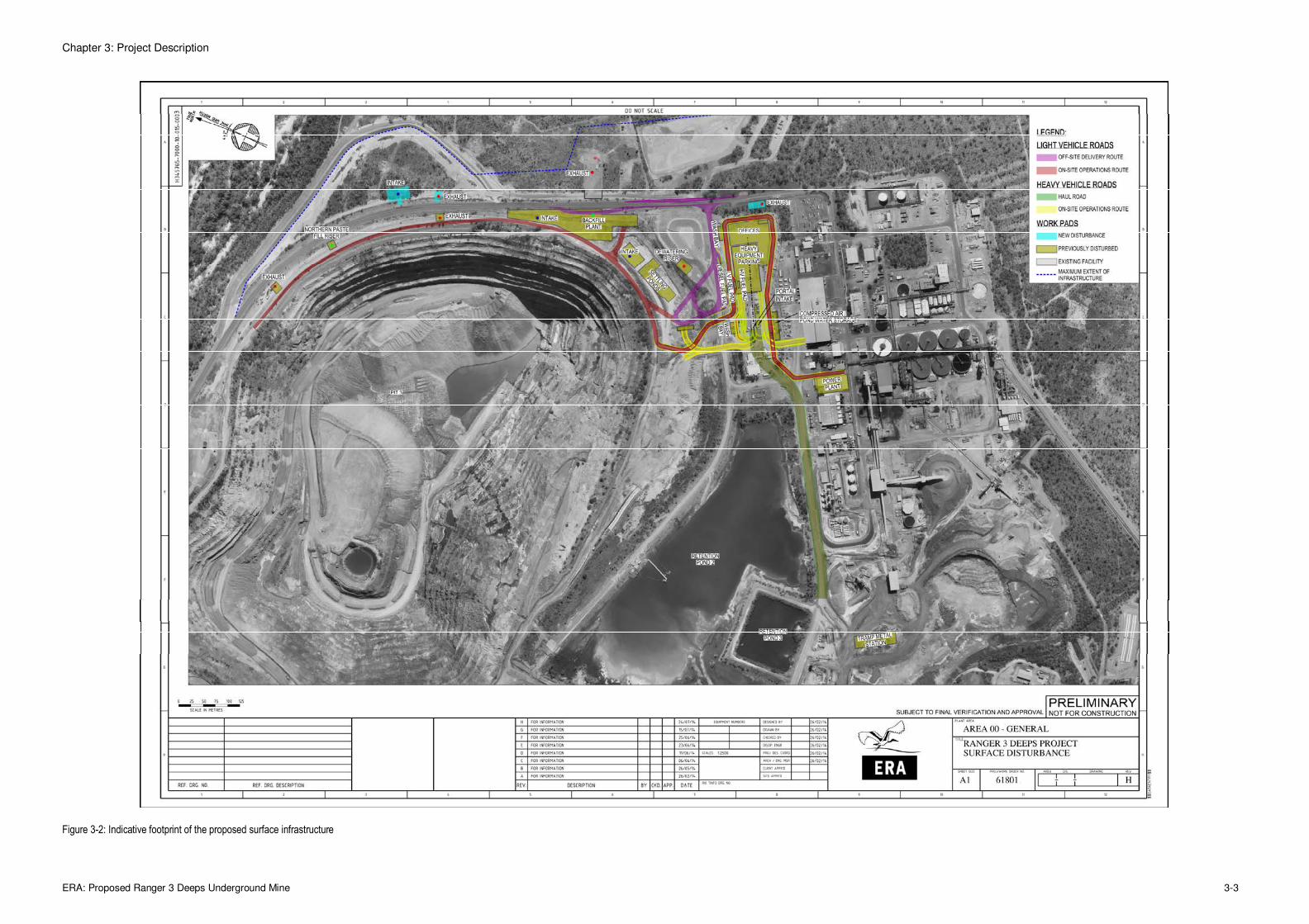
Figure 3-2 shows the indicative location of the proposed infrastructure and the maximum
eastern extent of any ventilation infrastructure.
The infrastructure footprint covers approximately 11 ha of land almost entirely within the
current operating area.3 Apart from 0.3 ha of new vegetation clearing for ventilation
infrastructure and 0.4 ha of clearing, previously approved and completed for the exploration
decline ventilation (exhaust 3a), no new clearing is planned. However, during construction of
the decline it is possible that unexpected ground conditions or other engineering difficulties
may require some ventilation shafts to be relocated.
Further detail of the approximate dimensions of each significant Project infrastructure
component is provided in Section 3.5.
3 The stated 11 ha footprint is effectively the area within the polygons encompassing the entire Project infrastructure
including haul roads and batters. As such this area includes concrete footings and bunded areas, earthen hardstands surrounding infrastructure, park-up areas with compacted gravel base and space in between infrastructure including temporary construction lay-down areas (almost entirely on previously cleared, disturbed areas),
Chapter 3: Project Description
ERA: Proposed Ranger 3 Deeps Underground Mine 3-3
Figure 3-2: Indicative footprint of the proposed surface infrastructure
Chapter 3: Project Description
ERA: Proposed Ranger 3 Deeps Underground Mine 3-4
If a ventilation shaft needs to be relocated, additional clearing of minor areas of previously
disturbed vegetation may be required. Any relocation would be close to current operations
and between the main access road and the boundary shown on Figure 3-2 labelled
"Maximum extent of infrastructure". Under these circumstances, an area not exceeding
50 m x 50 m (0.25 ha) of remnant vegetation may be cleared to establish a foundation for the
relocated ventilation shaft.
Any new clearing will be carried out using heavy machinery. The cleared vegetation will be
pushed to the boundary of disturbance and left to decompose, providing a temporary barrier
to reduce potential increases in sediment loads entering Magela Creek. Clearing will be
undertaken in accordance with ERA's land use stewardship management plan.
3.3 RANGER 3 DEEPS UNDERGROUND MINE
3.3.1 The Ranger 3 Deeps Uranium Deposit
The geology of the Ranger 3 Deeps resource is complex and has been the subject of
numerous studies and interpretations since its discovery in the mid-2000s. The Ranger 3
Deeps orebody formed within the 2.1 billion year old Paleo-Proterozoic4 rocks of the Cahill
Formation (Figure 3-3) and the age of the uranium mineralisation has been dated to around
1.75 billion years.
The resource is hosted within a complex north-northwest trending fault system at the contact
between the Cahill Formation upper mine sequence schists and lower mine sequence
carbonates. The exact location of the fault system is strongly influenced by the competency
contrast5 between these rock types.
The Ranger 3 Deeps deposit is believed to have formed within this zone when the
appropriate conditions of fault orientation, rock chemistry, rock permeability and mineralised
fluid availability combine. This resulted in the precipitation of uranium oxide in the form of
uraninite within fractures and spaces in the faulted rock. Minor amounts of copper,
associated with later open space quartz-chalcopyrite veins, are also found within Ranger 3
Deeps deposit.
There are two main styles of uranium mineralisation within the Ranger 3 Deeps deposit
(Figure 3-4). Greater than 65% of the uranium resource occurs within the chlorite schists of
the upper mine sequence. The remainder occurs deeper, within the lower mine sequence
carbonates, hosted by bedding parallel schist horizons (or layers). In three dimensions, the
deposit resembles a flattened cigar shape, trending north-northwest and plunging around 12
degrees to the south. Figure 3-4 shows the main rock units and the mineralised fault zones
of the upper and lower mine sequence.
4 Rocks formed between 2,500 to 1,600 million years ago.
5 Differing level of resistance to deformation.

Chapter 3: Project Description
ERA: Proposed Ranger 3 Deeps Underground Mine 3-5
Figure 3-3: Regional geology within the location of the Ranger 3 Deeps uranium deposit

Chapter 3: Project Description
ERA: Proposed Ranger 3 Deeps Underground Mine 3-6
Figure 3-4: Typical west-east cross-section of the Ranger 3 Deeps deposit
3.3.2 Exploration and Drilling
Extensive exploration drilling of the Ranger 3 Deeps ore body was completed from within the
underground exploration decline in dedicated drilling drives or cuddies with sufficient size to
accommodate the drilling equipment. Drilling fans, a radial pattern of drill holes originating
from the same drilling location, were completed from each cuddy (Figure 3-5). The drilling
cuddies were established at depths ranging from -120 m to -310 m from the surface.
The main objectives of the underground drilling program were to:
(a) Increase confidence in the known mineralisation to allow conversion to a measured
and indicated mineral resource;
(b) Understand the distribution and abundance of deleterious minerals such as carbonate;
(c) Support the development of prefeasibility level mine plans; and
(d) Explore those prospective areas with less historical drilling, particularly at the northern
end of the deposit.

Chapter 3: Project Description
ERA: Proposed Ranger 3 Deeps Underground Mine 3-7
The drilling program has defined the Ranger 3 Deeps resource as being 1.1 km long and
0.4 km wide, located between the approximate Reference Levels RL-150 m and RL-500 m.
Figure 3-5: Location of the Ranger 3 Deeps resource, exploration decline and drilling fans
Mineral resource estimates for the Project are publically reported by ERA and are
summarised in Table 3-1. The estimates are categorised as measured, indicated or inferred.
A measured mineral resource is one that has been estimated to a high level of confidence
and which can support detailed mine planning and final evaluation of the economic viability of
the deposit. An indicated mineral resource is one that has been less well defined but is
defined in sufficient detail to develop a mine plan and estimate the economic viability of the
deposit. An inferred mineral resource is one where the quantity and grade of the resource is
estimated based on limited geological evidence and sampling, and has a lower level of
certainty. While inferred resources cannot be used to determine economic viability, there is
an expectation that a portion of the inferred resources will be converted to indicated
resources following further exploration. Similarly, a portion of the indicated resources may
be converted to measured resources as exploration continues.

Chapter 3: Project Description
ERA: Proposed Ranger 3 Deeps Underground Mine 3-8
Table 3-1: Ranger 3 Deeps measured, indicated and inferred resources (20 June 2014)
Category Ore(Mt) Grade U3O8 (%) Contained U3O8 (t)
Measured 2.96 0.29 8448
Indicated 5.73 0.25 14,276
Inferred 3.23 0.31 9,896
Total 11.91 0.27 32,620
# Report to Australian Stock Exchange, 20th June 2014; rounding differences may occur
Figure 3-6: Typical cross section showing drilling intersecting two styles of mineralisation

Chapter 3: Project Description
ERA: Proposed Ranger 3 Deeps Underground Mine 3-9
Figure 3-6 is a typical cross section of the ore body (cross section marked on Figure 3-5).
It shows a drilling fan intersecting mineralisation (at a cut-off grade of 0.12% U3O8) within the
chlorite schists of the faulted upper mine sequence/lower mine sequence contact zone, and
lower down in the chlorite schist horizons of the lower mine sequence carbonates.
The geological break between the schists of the upper mine sequence and the carbonates of
the lower mine sequence is highlighted by the blue line which is offset by controlling
mineralised faults (red lines). The main Ranger 3 Deeps structure is a major fault line thought
to exert significant control on the position of mineralisation.
3.3.3 Mine Design
3.3.3.1 Mine Access
Vehicular access to the mine will be from the existing Ranger 3 Deeps exploration decline
(Figure 3-7). The decline extends from a covered portal at the surface, located southeast of
the existing Pit 3 and north of the Ranger mine processing plant. Personnel, most materials
and broken ore (mined ore) will be transported via the decline. Some materials such as
backfill will be transported into the underground via cased bore holes.
Figure 3-7: Existing underground facilities showing exploration decline and exhaust
The decline passes through the weak chloritic schist at the roof of the ore body (the hanging
wall) at the top of the upper mine sequence and into the competent carbonate rocks of the
lower mine sequence at around 360 m below surface. The lower part of the decline will be
located in the unmineralised basement (or footwall) of the ore body.
Air for ventilating the mine will enter via the decline and a number of vertical ventilation shafts
(the intakes). Emergency secondary egress for personnel will be via intake 3.
3.3.3.2 Mining Method and Sequence
The proposed mining method aims to achieve selective and efficient extraction of ore whilst
ensuring a safe working environment. The selected mining method is called transverse open
stoping. A cemented paste fill will be used to backfill mined out areas (or stopes) to prevent
mine subsidence.

Chapter 3: Project Description
ERA: Proposed Ranger 3 Deeps Underground Mine 3-10
The method comprises the following steps:
1. Tunnels, known as ore drives, are excavated into the mineralised ore body both above
and below to access the ore targeted for extraction (Figure 3-8a).
2. Long holes are drilled into the target ore from these ore drives (Figure 3-8b).
3. Explosives are placed in the holes, and blasting occurs. A chamber, known as a stope,
filled with broken ore is formed (Figure 3-8c).
4. Broken ore is removed from the stope via the lower ore drive by loader, loaded onto
trucks, and transported to the surface for processing.
5. When the stope is empty the lower stope access is sealed with a bulkhead made of
steel mesh and concrete (Figure 3-8d) and the void is filled with paste, delivered from
the backfill plant (at the surface), via the ore drive above (Figure 3-8e). The paste (a
mixture of tailings, low grade rock, cement binder and water) is delivered to the stope
from the surface via a cased borehole in combination with underground pipes.
6. Paste is allowed to cure (harden) before adjacent stopes are mined.
The method is described as transverse because the ore drives are aligned perpendicular to
the strike of the ore body. This method is generally preferred over the alternative, longitudinal
open stoping (ore drives parallel to the strike), where ore body thickness exceeds 15 to 20 m
and where multiple work places are desirable.
Figure 3-8: Diagrammatic representation of the transverse open stoping method
The mining method can be entry or non-entry, where non-entry methods do not require
workers to enter the mineralised zone, thereby reducing radiation exposure of the workforce.
The geometry of the Ranger 3 Deeps orebody is unsuitable for a non-entry method as it
would require extremely tall stopes which would be impractical and uneconomic to mine.
However, a flexible approach will be taken so that if areas suitable for non-entry methods are
identified they will be evaluated and if feasible, non-entry methods may be used in those
areas.
A schematic of the proposed underground mine is shown in Figure 3-9. Stopes are shown
in solid shading, development in yellow, exploration decline in grey, intake ventilation in blue
and exhaust ventilation in red.

Chapter 3: Project Description
ERA: Proposed Ranger 3 Deeps Underground Mine 3-11
The mine will extend to a depth of approximately 475 m below the surface and the mine plan
assumes an interval of 25 m between mine levels. Stopes will be single lift only, that is, open
to a maximum of one level interval each before backfilling occurs. The stope dimensions are
assumed to be up to 20 m wide by 25 m high, with an average length of approximately 30 m.
The stope length will vary and will equal the width of the ore body in narrow sections of ore,
but there may be multiple stopes across wider parts of the orebody. Geotechnical conditions
preclude the use of larger stopes and stope size may be further reduced following more
detailed geotechnical investigations.
The mining sequence will be bottom-up, where the lowest stopes are mined first. Mining will
retreat from the periphery of each mining district (south, central, north and far north) towards
the centre, where the mine access and intake shafts are located, and generally from the
hangingwall (east) to the footwall (west). This ensures that mining always retreats towards
the source of fresh air. This strategy greatly reduces the exposure of personnel to air
returning from active work areas, thereby minimising exposure to airborne radiation.
Figure 3-9: View of proposed underground mine, looking south-west
The mining sequence will vary slightly depending on the position in the ore body. At the
peripheries, where ore body width tends to be narrow, an en-echelon sequence of stoping
will be adopted, Figure 3-10a. In the centre, where the ore body is thicker, a primary-
secondary sequence will be adopted. This is where every second stope (or primary stope) is
mined and filled before mining the alternate stope (secondary stope), Figure 3-10b. This
sequence addresses the geotechnical limitations while allowing a high resource recovery
rate.

Chapter 3: Project Description
ERA: Proposed Ranger 3 Deeps Underground Mine 3-12
(a) en-echelon sequence 2 mine sequence unmined paste-filled
4 5 1 2 3 4 5
7 8 9 10
6 7 8
(b) Primary–secondary sequence 2 mine sequence unmined paste-filled
1 2 3 4 5
6 7 8 9 10
Figure 3-10: Indicative stope mining sequences
3.3.3.3 Backfill Method
Stope voids will be backfilled with an engineered paste composed of tailings, aggregate and
cement binder. The binder consolidates the paste and gives it enough strength to be self-
supporting as an exposed face when the adjacent stope is mined out. The properties of the
paste, including its strength and viscosity, can be varied by changes to the mix design.
The purpose of backfill is to provide long-term support for the underground excavations and
prevent collapse of any mined out areas (stopes). The use of backfill also eliminates the
possibility of surface subsidence after mine closure. Paste is relatively impermeable to water
and will restrict the movement of fluids through the mined out areas.
The paste will be produced at a mixing plant (the backfill plant) on the surface and reticulated
underground via a pipe network located in cased bore holes and underground drives. The
paste reticulation design is illustrated in Figure 3-11. The main zone of stoping is serviced
by paste pipes located in two cased boreholes that originate at the paste plant. One angles
north, and one south to minimise the reticulation route to the northern and southern stopes
respectively. The driving head developed is sufficient to reticulate to all planned main zone
stopes without pumping. Two holes are preferred for redundancy, should one hole become
blocked. For a smaller number of stopes, located in the far north district (refer Figures 3-9
and 3-11), the paste will be pumped via a pipe located on the surface, along the crest of
Pit 3, to a cased bore hole above the main decline in the north.

Chapter 3: Project Description
ERA: Proposed Ranger 3 Deeps Underground Mine 3-13
Bulkheads will be constructed at the lower access points of the backfilled stopes to confine
the paste to areas where it is needed. The bulkheads will be engineered structures
comprising steel cable lattice that is bolted to the rock walls and sealed with shotcrete (a type
of sprayed concrete). The rate of paste placement will be managed so that the hydraulic
pressure against the bulkheads is controlled. The lower level of the stope will first be
backfilled to just above the bulkheads and then allowed to consolidate. The pour will continue
after the paste from the initial pour becomes stable, typically after about 24 hours. Activities
near the bottom of stopes being filled will be restricted while backfilling is in progress.
Once in situ, the strength of the paste will increase over time. Typically a curing time of
around 28 days will be allowed before excavating adjacent stopes and exposing unsupported
paste fill surfaces.
Figure 3-11: Indicative paste reticulation design
Backfill operations will ramp up to a peak backfill delivery rate of 150 m3 per hour in 2019.
Planned backfill delivery rates are summarised in Table 3-2.
Table 3-2: Backfill delivery rates
Metric Unit 2015 2016 2018 2019 2020
Backfill volume 1,000 m3 11 368 531 589 549
Plant operating time h 71 2,500 3,500 3,900 3,700
Paste plant utilisation – 5% 30% 40% 45% 40%

Chapter 3: Project Description
ERA: Proposed Ranger 3 Deeps Underground Mine 3-14
3.3.3.4 Dimensions and Gradients
Lateral development dimensions of the underground mine are shown in Table 3-3. The
decline, level accesses and footwall drives are sized to accommodate a loaded truck and
1,600 mm diameter ventilation duct. The ore drives are designed to accommodate an
underground load-haul-dump loader with 0.9 m of clearance on either side.
Table 3-3: Lateral development dimensions
Type Width
(m)
Height
(m)
Typical gradient
Access decline 5.5 6.0 1 : 6
Level access, footwall 5.5 6.0 1 : 50
Ore drives, return air drivesa and sumps 5.0 5.0 1 : 6
a Return air drives link working areas to the main exhaust air system
Mine development will have a consistent gradient to prevent water pooling in the mine.
The mine plan assumes that the intake and exhaust ventilation shafts will be excavated to
3.0 m diameter. The ventilation shafts will be supported with up to 100 mm of shotcrete,
giving an internal diameter of 2.8 m. Geotechnical conditions may preclude the use of larger
ventilation shafts.
3.3.3.5 Mine Ventilation
The underground mine must be ventilated to supply fresh air to personnel working in the
mine. The ventilation system removes exhaust gasses from diesel engines, radon gasses
from the rock surfaces, and gasses generated during blasting. Fresh air is drawn into the
mine through intake vents and removed from the mine through exhaust vents.
The mine ventilation system is designed to cater for the maximum planned production rate of
the mine.
The quantity of air required for adequate mine ventilation is determined taking into account
the amount of diesel exhaust6 and heat created by the underground mining fleet, the amount
of heat contained within the natural rock and the modelled radon decay product
concentrations in all work areas.
Figure 3-12 shows the indicative arrangement of the main airways in the mine, the intake
and exhaust vents7, the main decline and their relationship with Pit 3.
6 Assumes emission reduction technology will be installed on underground trucks to reduce diesel particulates.
7 Exhaust 2 and exhaust 3 are twin exhaust shafts but are shown as single lines for simplicity.

Chapter 3: Project Description
ERA: Proposed Ranger 3 Deeps Underground Mine 3-15
Figure 3-12: Ventilation schematic showing indicative locations of airways
Fresh air is drawn into the mine towards the active work areas and exhausted away from
areas occupied by the workforce. Figure 3-13 illustrates typical ventilation of a stope where
air is drawn in through an intake (blue), directed along the mine development (green) and
into the ore drives (cyan). The exhaust gasses from the ore drives and stopes are then
directed to the exhaust end of the ore drives and through the stoping area (purple). This
maintains a healthy work environment for workers and minimises exposure to engine
exhausts and the radon gas emitted from the orebody.
Figure 3-13: Mine ventilation during long-hole drilling of a secondary stope

Chapter 3: Project Description
ERA: Proposed Ranger 3 Deeps Underground Mine 3-16
3.3.4 Plant and Machinery
The size of the underground mobile equipment fleet will vary over time. An indicative guide to
the mobile fleet over the duration of the Project is shown in Table 3-4.
Table 3-4: Indicative size of the mobile underground equipment fleet
Item Indicative type 2015 2016 2017 2018 2019 2020
Trucks Caterpillar AD55 3 5 6 4 5 3
Load-haul-dump loaders Caterpillar R2900G 3 4 5 4 4 3
Jumbo drills Sandvik DD421-60 4 4 4 2 – –
Production drills Sandvik DL421 1 2 3 3 3 3
Cable bolter Sandvik DS421 1 1 1 1 1 1
Shotcreter Normet Spraymec 2 2 2 1 – 1
Agitator Jaycon 2 3 3 1 – –
Charge up vehicle Normet Charmec 2 3 3 3 3 2
Integrated tool carrier Caterpillar IT28 2 2 2 2 2 2
Grader Caterpillar 120M 1 1 1 1 1 1
Light vehicle Toyota Landcruiser 14 16 16 16 16 16
Water truck – 1 1 1 1 1 1
3.3.5 Annual Production Volumes
Indicative production quantities for the Project are summarised in Table 3-5, having regard to
the current resource estimate and the period in which mining is to occur. The quantities
exclude details on currently stockpiled ore. The information in this section has been
prepared solely to give a sense of the scale of the mining for the Project for the purpose of
obtaining the necessary environmental approvals required for the Project. It is based on
broad assumptions relating to, amongst other things, ore grade and mining conditions,
minable quantities may change with increasing orebody and geotechnical knowledge (refer
the "Important Note" and "Disclaimer" at the front of this document).
Project generated ore is intended to be hauled directly to the existing "run of mine" (ROM)
stockpile. As high grade material it will be prioritised for processing and thus inventories
would be very limited in extent, particularly as peak mine production rates are approximately
half the plant processing rate. Currently employed storage and management practices for the
ROM will continue unchanged.

Chapter 3: Project Description
ERA: Proposed Ranger 3 Deeps Underground Mine 3-17
Table 3-5: Indicative Ranger 3 Deeps ore production schedule
Item Unit Total 2015 2016 2017 2018 2019 2020
Total ore1 production kt 6,750 80 1,140 1,610 1,490 1,380 1,050
Category 32 production kt 200 35 70 94 1 – –
Category 23 production kt 350 70 150 130 4 – –
Waste4 mined kt 540 184 268 88 – – –
Backfill volume 1000 m3 2,470 10 370 530 590 550 420
Note: the production quantities in this section are not intended to be "production targets" for the purpose of the ASX Listing Rules. 1 Above 0.12% U3O8. Average ore grade 0.274% U3O8. 2 "Category 3" material: 0.08-0.12% U3O8 3 "Category 2" material: 0.02-0.08% U3O8 4 Waste material: below 0.02% U3O8
3.4 PROCESSING
3.4.1 Processing Methods
Ranger 3 Deeps ore will be processed through the existing processing plant using the same
chemical methods as described in Chapter 2 and illustrated in Figure 3-15. The amount of
material entering the plant is expected to remain similar to existing operations. However,
6.75 Mt of Ranger 3 Deeps ore will replace a similar amount of low grade stockpiled ore that
would otherwise have been processed.8 Surplus low grade stockpiled ore will be disposed
into Pit 3 at mine closure. Consequently, the tailings and waste streams are expected to
remain at similar levels to that produced by the current operations.
The Ranger 3 Deeps ore, particularly ore from the upper mine sequence has very similar
mineralogy to that of the previously mined Pit 3 ore. Figure 3-14 graphically illustrates this
with a comparison of the ore mineralogy of average Ranger 3 Deeps ore and the 2013 leach
feed from the existing Ranger plant.
Leach response tests from Ranger 3 Deeps and Pit 3 ore also yield very similar results, with
ore samples of similar head grade demonstrating no significant difference in observed leach
response.9 The very similar mineralogy and the leach response tests for Ranger 3 Deeps and
Pit 3 ore mean that a blended ore feed to the plant will produce tailings that are almost
indistinguishable from that currently produced at Ranger.
8 The processing plant has a capacity of 2.4 Mt/annum and this processing rate will be maintained. Ranger 3 Deeps ore
will be supplemented with stockpiled, low grade ore to make up the total ore feed to 2.4 Mt.
9 These tests compared a Pit 3 bulk control sample from a geo-metallurgical test programme conducted in 2009 and 2010 with a composite sample from the current Ranger 3 Deeps drilling program.

Chapter 3: Project Description
ERA: Proposed Ranger 3 Deeps Underground Mine 3-18
Figure 3-14: Mineral abundance of 2013 leach feed and Ranger 3 Deeps composite samples
Processing of the combined existing stockpiled ore and the Project generated ore will
continue to use process water drawn from the tailings dam inventory. Given the similarity in
mineralogy of existing and Project ore and the common leach response of the materials the
process water quality will be effectively unchanged. The quantity of process water used in,
and generated by, the processing of the combined ores will be equivalent to that associated
with processing only existing stockpiled ore in the absence of the Project.
While Pit 3 and Ranger 3 Deeps ore is very similar, ore from the lower mine sequence is
known to have higher levels of carbonate, so average Ranger 3 Deeps ore will have higher
carbonate content than Pit 3 ore. Since higher carbonate ore will consume more sulfuric acid
if the ore is processed directly through the plant, a beneficiation process may be used to
lower carbonate content prior to processing in order to reduce acid consumption and cost.
Depending on the carbonate content, both the direct feed and beneficiation approaches may
be employed at various times, concurrent with mine sequencing and stockpiling.
Ore that requires beneficiation will be subjected to sorting before it is fed to the processing
circuit (refer Figure 3-15). Test work demonstrates that sorting will effectively reduce the
carbonate to acceptable levels. The existing ore sorter has sufficient capacity to process the
anticipated portion of high carbonate Project ore. The sorter can be configured for either
optical sorting (based on colour) or radiometric sorting. The general sorting mechanism
identifies, and then rejects or accepts, individual large particles (greater than 20 – 25 mm)
passing the detector array using air jets and generates two streams, beneficiated ore and
carbonate reject material. The carbonate rejects are classified as waste rock and are
directed to the waste rock stockpile (suitable for pit backfill or land fill).

Chapter 3: Project Description
ERA: Proposed Ranger 3 Deeps Underground Mine 3-19
Figure 3-15: Existing processing circuit with high carbonate ore pathway

Chapter 3: Project Description
ERA: Proposed Ranger 3 Deeps Underground Mine 3-20
3.4.2 Consumables
Table 3-6 shows the estimated additional consumables required for the Project. The most
significant consumables used will be cement for backfill production, sulfuric acid and lime for
processing, diesel for the heavy equipment fleet, and shotcrete for stabilising tunnels and
other structures.
Transport of hazardous substances along the Arnhem and Kakadu Highways (primarily
cement, sulfuric acid, quicklime and diesel) is discussed in further detail in Chapter 12.
Table 3-6: Forecast annual consumables for the Project
Reagent Unit
Project forecast usage
2014 2015 2016 2017 2018 2019 2020
Alamine 336 kL - 1 15 34 36 33 28
Anhydrous ammonia kt - 0.1 1 2 2 1 1
Cement1 kt - 2 23 54 55 57 50
Diesel ML 4 7 13 15 13 15 13
Explosives2 t - 300 810 1,050 800 640 560
ShellSol 2046 (kerosene) kL - - 400 400 400 400 400
Quicklime kt - - 11 18 15 15 12
Sand/aggregate kt - 7 15 11 5 0.3 -
Sodium hydroxide kL - 1 11 27 29 27 23
Sulfuric acid kt - - 30 50 40 40 30
Notes: 1 Includes cement for backfill and shotcrete 2 Bulk and packaged explosives
3.4.3 Product
As outlined in Chapter 2, uranium oxide product (a dark green powder) is packed into 200 L
steel drums, which are sealed and transported by road to a secure holding facility in Darwin
using an accredited transport company. The containers are normally railed to Adelaide and
exported from Adelaide Port; however, they have also been exported from Port Darwin in the
past and this remains an export option.
The Project does not change the current holding facilities or transhipment arrangements for
the export and supply of product to conversion facilities and ultimately electric utilities in Asia,
Europe and North America. Full details of transhipment of uranium product cannot be
disclosed due to Australian Safeguards and Non-Proliferation Office (ASNO) security
requirements.

Chapter 3: Project Description
ERA: Proposed Ranger 3 Deeps Underground Mine 3-21
3.5 NEW INFRASTRUCTURE
The Project consists of a number of surface infrastructure systems that support underground
mining of the orebody. These include:
� A backfill system (including a tailings dewatering facility and cement storage silos) to
produce and deliver paste to the underground mine.
� A mine ventilation and refrigeration system to provide cool, fresh air to, and remove
exhaust air from, underground areas.
� A power plant to provide electrical power for the surface infrastructure and
underground mine.
� A dewatering system for the underground mine.
Supporting infrastructure for the Project includes:
� Diesel storage to provide fuel for vehicles used in the underground mine.
� A silt trap, settling pond and oil/water separator to treat water from the underground
mine.
� A water supply system to provide water for use on the surface and underground.
� A compressed air system for equipment in the underground mine.
� Reticulation systems for the distribution of air, water and electrical power between
equipment on the surface and underground.
� A tramp metal facility to remove any metal from the crusher feed for preparing
aggregate for backfill production
� Relocated explosives preparation and secure storage.
� A shotcrete transfer station used to transfer shotcrete from a surface only delivery
vehicle to a vehicle for use underground.
� Office, showers and ablutions facilities.
� Roads, fences, gates and controlled areas.
The feasibility study and detailed engineering design phase will establish the final layout,
equipment selection, configuration (such as reticulation corridors) and detailed construction
process. ERA will ensure all new infrastructure is built safely, cost effectively and to a
standard that meets statutory building codes and cyclone standards. To help achieve this
goal, all Project construction standards will align with the requirements of the NT Work
Health and Safety (National Uniform Legislation) Act 2011 and regulations, the applicable
National Codes of Practice for Construction, and the established ERA site and safety
standards. All Project surface infrastructure will be built above the 1:100 year flood level.
Figure 3-16 shows the location of all proposed surface infrastructure for the Project, with the
exception of the explosives storage facility. This facility will be located on the north-west side
of Pit 3.

Chapter 3: Project Description
ERA: Proposed Ranger 3 Deeps Underground Mine 3-22
Figure 3-16: Indicative location of the proposed infrastructure for the Project

Chapter 3: Project Description
ERA: Proposed Ranger 3 Deeps Underground Mine 3-23
3.5.1 Backfill Plant and Tailings Dewatering Plant
Backfill will be used to fill the mined out stopes and support the surrounding rocks so that
adjacent sections of the mine can be mined safely. Consequently, a minimum backfill
strength must be achieved.
Backfill will typically be a mixture of tailings (from the processing plant), aggregate (crushed,
low grade rock), cement and water. A small amount of an additive (rheology modifier) may be
added to the mixture to make it easier to pump underground and/or improve the cured
strength. Each of these paste constituents is discussed in more detail below. Other
properties such as moisture content and density will also be regulated to ensure adequate
backfill strength.
Backfilling is a well-established process used in underground mines around the world. The
backfill preparation equipment used in the Project backfill plant is similar to other established
underground mines.
Overview
The backfill plant and tailings dewatering plant will comprise two buildings: one building
houses the tailings dewatering equipment, while the second building houses the equipment
for mixing the backfill components into a paste that can be distributed underground.
A portion of the Ranger processing plant tailings will be extracted and pumped from the main
tailings disposal pipelines to the tailings dewatering plant. Hydro-cyclones will remove the
slimes10 prior to washing with brine11, which will remove most of the remaining low pH (acidic)
and saline water. The tailings will then be dewatered with either dewatering screens or
horizontal belt filters. The hydro-cyclone overflow and water outflow from the tailings
dewatering equipment is scheduled to be sent to Pit 3 with the main tailings stream. 12 The
quantity of slimes returned to the main tailings steam is very small compared to the total
inventory of tailings, and will have no discernable influence on tailings consolidation in Pit 3.
The dewatered tailings will be combined with the crushed aggregate (comprising low grade
rock), cement and rheology modifiers in a paste mixer and either gravity fed or pumped into
the mine.
The backfill plant and tailings dewatering plant are shown in Figure 3-16 (refer items 7
and 8). An indicative image of the backfill plant and tailings dewatering plant, showing the
arrangement of the major equipment, is shown in Figure 3-17. The backfill plant and tailings
dewatering plant buildings will be approximately 50 m long x 25 m wide x 20 m high and
56 m long x 18 m wide x 20 m high respectively.
A schematic flow diagram of the backfill plant and tailings dewatering plant that shows the
connections between the major equipment is provided in Figure 3-18.
10 Slimes are the finer particles. Their removal greatly enhances filtration performance and improves paste properties
(cured strength at target cement composition).
11 The brine is derived as a by-product of the existing pond water treatment plant. It is generated via micro filtration and reverse osmosis. The advantage of washing out the acidic fluids from the tailings is better utilisation of the cement, and ultimately greater strength of the cemented paste.
12 The placement of tailings into Pit 3 is subject to final regulatory approval via the MTC process.

Chapter 3: Project Description
ERA: Proposed Ranger 3 Deeps Underground Mine 3-24
Tailings
The Ranger processing plant produces tailings slurry containing fine and coarse particles
(the leached remains of ground ore) and process water. Only the coarse particles will be
used in the backfill paste. A pump is used to send the tailings through a pipeline to a storage
tank in the tailings dewatering plant. From there the tailings will be pumped through a
number of hydro-cyclones where the coarse and fine particles are separated by centrifugal
force. Brine from the existing reverse osmosis plant will then be used to wash the coarse
particles to reduce acidity and salinity.
The washed coarse particle slurry will then flow by gravity to the dewatering facility where the
process water is removed using either vibrating dewatering screens or belt filters, or possibly
hydro-cyclones for some tailings. The coarse particles will exit the dewatering facility onto a
conveyor that will transport the dewatered product to a storage bin in the backfill plant.
Wash water from the dewatering equipment is sent to a discharge water storage tank at the
dewatering plant. The reject fine particles from the top of the cyclone will flow by gravity to
the same storage tank. The resultant slurry will be pumped from the storage tank to one of
the main Ranger tailings pipelines and discharged to Pit 3.
Figure 3-17: Indicative image of the backfill plant and tailings dewatering plant
Hydro-cyclones Backfill plant
Cement silo
Tailings
dewatering plant
Aggregate
Dewatering
screens / filters
Mixer
Process
tailings Discharge
water

Chapter 3: Project Description
ERA: Proposed Ranger 3 Deeps Underground Mine 3-25
Figure 3-18: Schematic flow diagram of the tailings dewatering plant and backfill plant
* MFRO Water is discharge water, or "brine", from the existing micro filtration reverse osmosis plant
Aggregate
Aggregate (small rocks ≤ 20 mm screen diameter) will be made by crushing and screening
low grade ore from existing stockpiles. A front-end loader will be used to feed the crusher
and load crushed aggregate into a dump truck for transport to the feed hopper at the backfill
plant. A small backup stockpile of aggregate will also be kept near the feed hopper at the
backfill plant in case aggregate from the crusher is not available.
Cement
Cement will be delivered to the backfill plant in trucks and pneumatically conveyed (blown
with air) into a silo. During unloading, the pneumatic conveying air will exit the silo through a
vent, which is fitted with a dust collector. The cement silo will be about 6.5 m in diameter and
14 m high and hold approximately 1,300 t of cement (sufficient for four days of backfill
production).
Cement will be transferred to the mixing plant using a commercially available sealed
conveying system.

Chapter 3: Project Description
ERA: Proposed Ranger 3 Deeps Underground Mine 3-26
Rheology 13 modifier
Additives, called rheology modifiers, may be added to the backfill to make it easier to pump.
The modifier can be a natural material, such as a clay/guar gum14 or a proprietary industrial
synthetic material. If feasible, laterite material (clay) from the mine site will be used in
preference to a supplied material.
Water
Pond water (described in Chapter 2) will be used to adjust the moisture content of the
backfill. Pond water will be pumped from Retention Pond 2 (RP2) into a storage tank in the
backfill plant.
Backfill
The aggregate and filtered and washed tailings will be transported using conveyors from their
feed hoppers into a mixer, where pond water and cement will be added in appropriate ratios.
A local control system will be used to control the ratio of feed materials. Paddles will mix the
feed materials to make the backfill (which will have the consistency of wet concrete). Backfill
will then be immediately distributed underground via boreholes and pipelines, flowing by
gravity or pumping (refer Section 3.3.3.3).
Backfill plant
The backfill plant will typically run for the duration required to fill a mining void (stope).
Consequently, utilisation of the backfill plant (and therefore backfill production) will vary each
year, reflecting the production rate, but is expected to peak in 2018 with a utilisation of
approximately 45%. Once the backfill is prepared, it is immediately piped underground. The
pipes will enter the ground immediately adjacent to the plant through holes drilled from the
surface to specific points in the mine. This allows the paste to be fed by gravity to most of the
mine. One area of the mine is too far away for this delivery method to be employed, so the
paste will be pumped to that area. Production will range from 350,000 m3 in 2016 up to
around 600,000 m3 in peak production years.
The tailings dewatering and backfill plants will be housed inside buildings with concrete floors
that will be bunded to catch spills. Moving equipment will be guarded to protect personnel.
An automated control system will be used to run the plant to maximise safety for the
operators and to help stop spills and protect the environment. Features of the system include
electronic shutdown functions that will ensure storage bins and tanks do not overflow in the
event of a blockage.
Dust generated from the transfer of aggregate will be managed with sprays using pond
water. The cement will be transported in sealed systems, with dust collectors where required,
to minimise the likelihood of dust particles becoming airborne.
It is expected that four people will be required to operate the backfill plant: two dump truck
drivers and two operators (one to monitor equipment performance and attend to
housekeeping, e.g. equipment washdown, and the other in the control room).
13 Flow and deformation properties (of the backfill).
14 A white powder produced from ground de-husked guar beans.
Chapter 3: Project Description
ERA: Proposed Ranger 3 Deeps Underground Mine 3-27
3.5.1.1 Maintenance Requirements
Equipment in the backfill plant is designed to last for the life of the underground mine. To
achieve this, a planned maintenance schedule will be carried out to keep the equipment in
good condition.
The equipment will be washed with pond water at the end of each operating campaign. This
will ensure that the equipment is clean and ready to be used again, or is ready for routine
maintenance. The washing water will discharge into the water storage tank in the tailings
dewatering plant.
3.5.2 Refrigerated Air and Ventilation System
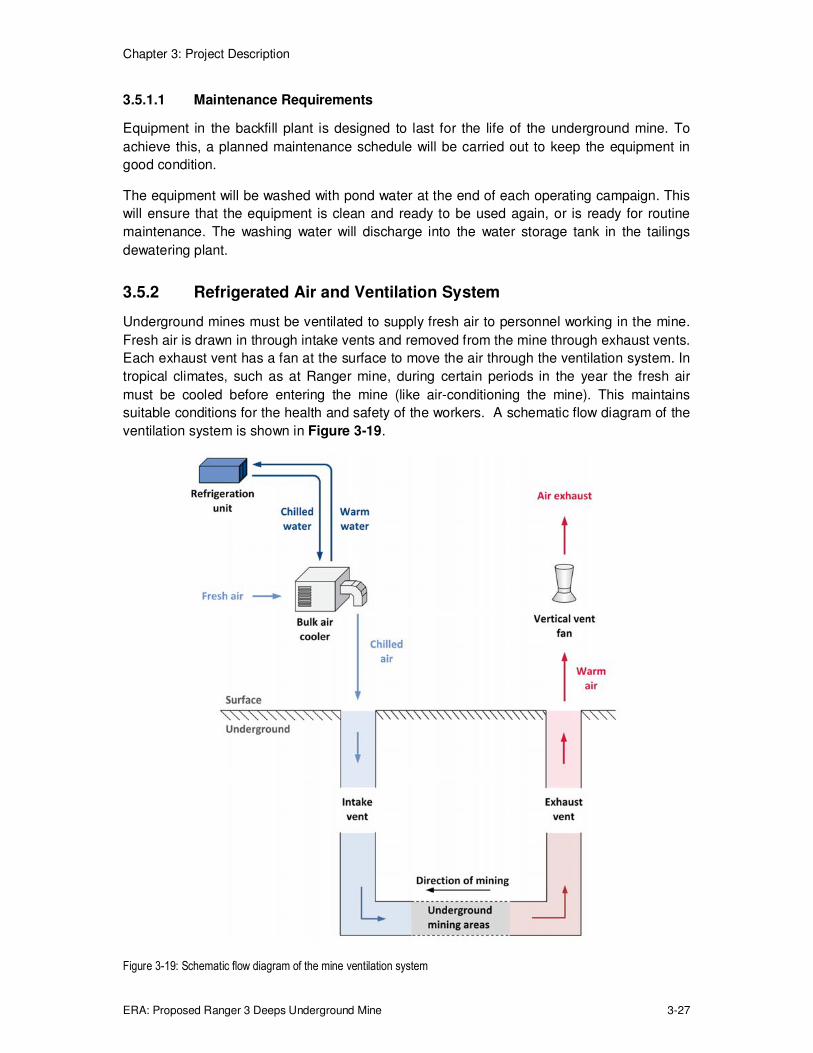
Underground mines must be ventilated to supply fresh air to personnel working in the mine.
Fresh air is drawn in through intake vents and removed from the mine through exhaust vents.
Each exhaust vent has a fan at the surface to move the air through the ventilation system. In
tropical climates, such as at Ranger mine, during certain periods in the year the fresh air
must be cooled before entering the mine (like air-conditioning the mine). This maintains
suitable conditions for the health and safety of the workers. A schematic flow diagram of the
ventilation system is shown in Figure 3-19.
Figure 3-19: Schematic flow diagram of the mine ventilation system

Chapter 3: Project Description
ERA: Proposed Ranger 3 Deeps Underground Mine 3-28
The equipment used in the Project mine ventilation system will be similar to that used at
other underground mines around the world.
3.5.2.1 Mechanical and Operational Characteristics
The Project mine ventilation system has been designed to ensure that adequate fresh air is
delivered to the active working face of the mine at all times. To achieve this, six exhaust
vents, three intake vents and intake air from the portal (mine entrance), are required (refer
Figure 3-16).15 The exhaust vents will comprise five new exhausts plus the existing
exploration decline exhaust (exhaust 3a).
To keep the temperature and humidity of the air in the mine within health and safety
guidelines, the air entering the mine will be cooled for up to six months of the year using bulk
air coolers. The bulk air coolers will typically be a simple box-like structure where ambient air
is drawn in and contacts chilled water sprays, thereby cooling the air.
Cooling of the water is achieved in compressed gas refrigeration units (using the refrigerant
R134a, as used in domestic applications). The refrigerant gas is compressed, cooled in a
fan-assisted, gas-to-liquid heat exchanger, and then further cooled by dropping its pressure.
The cold gas then cools water in another gas-to-liquid heat exchanger. The chilled water is
pumped to the bulk air cooler and the warmed refrigerant gas recirculated back to the start of
the circuit. Water is also returned from the bulk air cooler to the refrigeration unit.
As for domestic applications the refrigerant gas must be managed by licenced contractors,
be correctly contained and when no longer required, recycled or destroyed.
Ventilation intakes
Fresh air will enter the mine through three intake vents and the mine portal (mine entrance).
When necessary, air entering the mine will be cooled by a bulk air cooler and refrigeration
unit at each intake vent and two bulk air cooler and refrigeration units at the portal (which has
a higher air flow).
The intake vents will be installed on concrete foundations at each intake and exhaust vent,
and at the portal. The mine air cooling equipment at each fresh air intake consists of a:
� Bulk air cooler (approximately 14 m long, 11 m wide and 14 m high), which is attached
to the intake by ductwork, 3 m in diameter.
� Refrigeration unit (approximately 15 m long, 3 m wide and 3 m high).
At the portal, the ventilation intake equipment consists of two bulk air coolers (approximately
14 m long, 6 m wide and 14 m high) and two refrigeration units (approximately 15 m long,
3 m wide and 3 m high).
Cool water from the refrigeration unit is circulated through the bulk air cooler to cool the air
entering the mine. This warms the water which is returned to the refrigeration unit to be
cooled again. As the cooling water is circulated back to the refrigeration unit, ozone water
15 This is based on a particular mine size (largest of those contemplated in technical studies), vent diameter and fan
specifications. Ultimately the number and size of vents will depend on final mine design, geotechnical conditions and the air flow required to maintain safe working conditions.

Chapter 3: Project Description
ERA: Proposed Ranger 3 Deeps Underground Mine 3-29
treatment will be used to maintain water quality and prevent algal growth. This is important
as the recirculating water is in contact with the fresh air being delivered to personnel
underground.
As the air is cooled, water will condense out of the air and will be collected and released into
the storm water system and managed in accordance with ERA's standard water
management procedures.
The two bulk air coolers and refrigeration units located at the portal will be fitted with fans to
force air to flow through the cooler. Otherwise, air would be drawn in through the portal,
bypassing the bulk air cooler.
An indicative image of one of the fresh air intakes, showing the arrangement of the major
equipment, is shown in Figure 3-20.
Figure 3-20: Indicative image of a typical fresh air intake
Ventilation exhausts
There will be six exhaust vents, operating in four areas, to remove air from the mine. The
exhaust vents are currently expected to be 3 m in diameter and approximately 10 m high to
aid the dispersion of exhaust gases. To ensure adequate air flow, exhausts 2 and 3 will be
fitted with twinned exhaust vents. These twinned vents will be approximately 20 m apart and
will connect into mine workings in the same region.
The exhaust vents will extend close to the extremities of the underground mine. Each vent
will be fitted with a fan at the surface that creates a negative pressure drawing air in through
the ventilation intakes and portal, through the underground mine workings, and out the
exhaust vents. Mine planning will ensure that personnel at the mine working face are always
supplied with fresh air by commencing mining at the extremities and working towards the air
intakes.

Chapter 3: Project Description
ERA: Proposed Ranger 3 Deeps Underground Mine 3-30
The equipment at each ventilation exhaust consists of a vertical, cylindrical vent raise with a
fan inside. The vent raise is approximately 3 m in diameter, 10 m high and sits directly over
the exhaust shaft. The vent raise is supported by a concrete pad on the ground that is 8 m
long and 8 m wide.
An indicative image of one of the exhaust fan installations, showing the arrangement of the
major equipment, is shown in Figure 3-21.
Figure 3-21: Indicative image of a typical exhaust fan installation
Mine ventilation operation and control
In addition to the primary ventilation systems described above, there will be a significant
amount of secondary ventilation infrastructure installed underground to enable the
continuous supply of fresh air to all workplaces.
The secondary ventilation system is designed to take fresh air from the primary circuit and
distribute it to working areas with the use of secondary ventilation fans, ducting, ventilation
bulkheads, regulators and airflow controllers. The fans blow fresh air to the workplaces, with
the exhaust air generally flowing back along drives and eventually to the exhaust side of the
primary ventilation system. Ducting, ventilation bulkheads, regulators and airflow controllers
are used to control and direct the air to workplaces as required. Figure 3-13 illustrates the
use of these ventilation components in a typical underground mining situation.
A modern, automated control system will be used to operate the mine ventilation system.
This will allow a high level of control over the amount of ventilation in different areas of the
underground mine. One operator will be needed to control the mine ventilation system (from
the control room) and inspect the equipment.

Chapter 3: Project Description
ERA: Proposed Ranger 3 Deeps Underground Mine 3-31
3.5.2.2 Noise Considerations
Bulk air coolers and exhaust fans
The bulk air coolers will generate little noise, with the main sound sources being the cooling
water recirculation pumps and water spraying inside the cooler. Apart from the portal cooling
units, the intakes do not require fans as air is drawn in by the negative pressure created by
the exhaust fans.
There are six fans located on the six ventilation exhausts and two intake fans which push the
cold air into the portal. The fan in each exhaust stack will generate noise, most of which will
exit from the top of the exhaust vent since the fan and motor are located inside the above
ground portion of the vent. The two intake fans are located in the ducting between the bulk
air coolers and the portal. The noise level of these fans will be less than that of the exhaust
fans, as the duty is less and they pull air into the bulk air coolers. Tables 3-7 and 3-8 provide
the expected noise and sound pressure levels generated by the fans and indicate which fans
will require sound attenuation to meet specific sound limits. Sound attenuation is described
in more detail in Chapter 6.
Table 3-7: Exhaust fan noise levels
Exhaust ventilation fan
Exhaust ventilation number
Sound pressure level @ 1 m and 0 degrees from outlet (dBA)
Sound pressure level @ 1 m from casing (dBA)
Comment
Far north South
Exhaust 1 Exhaust 4
109 78 Sound attenuation required
North – a, b Central – a, b
Exhaust 2a, Exhaust 2b Exhaust 3a, Exhaust 3b
119 78 Sound attenuation not required
Table 3-8: Typical unattenuated fan sound pressure levels (dBA)
Frequency (Hz) 63 125 250 500 1,000 2,000 4,000 8,000 16,000 Overall
Sound pressure level at outlet 110 108 116 116 114 112 108 101 98 119
Sound pressure level at 1 m from casing
76 70 78 76 72 70 65 58 53 78
Sound pressure level at 7 m and 150 degrees from outlet
78 74 78 74 67 63 58 51 47 77
Sound pressure level at 1 m and 0 degrees from outlet
99 98 107 107 105 103 99 93 89 110
Refrigeration units
The refrigeration units include a bank of axial fans on the roof of each unit that draw air
across the heat exchangers. Five refrigeration units will be required, one at each of the three
ventilation intakes and two at the portal. Each unit will come with standard sound attenuation
and the sound power and noise levels generated by a typical sound attenuated unit at 100%

Chapter 3: Project Description
ERA: Proposed Ranger 3 Deeps Underground Mine 3-32
load are shown in Table 3-9. Noise from the refrigeration units is substantially lower than
that generated by the exhaust vent fans.
Table 3-9: Refrigeration unit noise levels at 100% load
Sound pressure levels at 9.1 m and ambient temperature of 40°C
Typical refrigeration unit in sound enclosure equipped with variable speed high flow fans
Frequency (Hz) 63 125 250 500 1,000 2,000 4,000 8,000 dB(A)
Sound Pressure Level (dB) 67.0 77.0 76.0 70.0 70.0 65.0 59.0 54.0 74.0
3.5.2.3 Maintenance Requirements
The equipment in the mine ventilation system is designed to last for the life of the
underground mine. To achieve this, routine maintenance will be completed to keep the
equipment in good condition. Maintenance will be undertaken on equipment at ventilation
intakes and exhaust when they are not being used.
3.5.2.4 Ventilation Shaft Construction Methods and Sequence
The ventilation shafts will be constructed by methods conventional to the Australian mining
industry. The construction method will be determined on an individual basis following detailed
analysis of the specific geotechnical conditions in each shaft location. All ventilation shafts
that extend to the surface of the underground mine will require some form of stabilisation in
the upper weathered zone. Potential means of achieving this include polyurethane resin or
cementitious grouting accompanied with piling, augering or pre-sinking. It is anticipated that
excavation of the remainder of each ventilation shaft will be completed by raise boring. Final
support of each excavation will include fibrecrete.
Potential shaft stabilisation and construction methods are described as follows:
Ground support and surface stabilisation
Ground stabilisation begins with the drilling of small diameter holes around the perimeter of
the proposed shaft followed by pressure injection of grout to fill open cavities and joints (refer
example shown in Figure 3-22). This is followed by piling or drilling of medium to large
diameter holes around the perimeter of the planned shaft and filling with steel cage
reinforcement and concrete.

Chapter 3: Project Description
ERA: Proposed Ranger 3 Deeps Underground Mine 3-33
Figure 3-22: Ventilation shaft slab showing completed pile driving
Construction methods
As outlined above, construction of the ventilation shaft will require some form of surface
stabilisation in the weathered zone. Once surface stabilisation is completed, the shaft is
constructed either by augering or conventional pre-sinking in the uppermost portion of the
vertical development in combination with raise boring (for the excavation in fresh rock).
Augering involves the drilling of a pilot hole through the centre of the slab, down to a
maximum depth of approximately 70 m. The pilot hole is progressively widened using cutting
heads with carbide teeth until the full shaft diameter is achieved. Ground support such as
fibrecrete and/or steel liners can be progressively installed during excavation. Raise boring of
the lower section of shaft would usually be completed first with augering then completed
down to the top of the raise bore.
Conventional pre-sinking, involves sinking the shaft down to a depth from which the
remainder of the shaft is completed by raise bore (Figure 3-23). This technique can only be
completed to a maximum depth of 50 m before a requirement for fixed headframe
infrastructure. The raise bore section is completed subsequently.

Chapter 3: Project Description
ERA: Proposed Ranger 3 Deeps Underground Mine 3-34
Figure 3-23: An example of a shaft pre-sink with raise bore pilot rod stabilisers
In both techniques, raise boring is completed through the lower portion of the vertical
development. Raise boring entails drilling of a pilot hole from the surface through to the
bottom of the shaft in the underground mine. A cutting head is attached to the raise borer
and the pilot hole is "reamed" out to final shaft diameter from the bottom through to surface
(or to base of weathered zone).
The final step of the shaft development is fibrecreting, which is applied remotely with rotating
spray nozzle lowered from the top of the shaft to the bottom.
Construction sequence
The mine ventilation equipment will be installed in stages as the underground mine is
developed. The sequence is shown in Table 3-10.
Table 3-10: Mine ventilation equipment installation sequence
Year Equipment installed
2016 Ventilation exhaust with fan
– Exhaust 4; Exhaust 3b; Exhaust 1
Ventilation intake with bulk air cooler and refrigeration unit
– Intake 3; Intake 2; Intake 1
Bulk air cooler and refrigeration unit - Portal
2017 – 2021 Ventilation exhaust with fan
– Exhaust 2a; Exhaust 2b

Chapter 3: Project Description
ERA: Proposed Ranger 3 Deeps Underground Mine 3-35
Each ventilation intake or exhaust will typically take about three months to build but may take
longer depending on the geotechnical conditions encountered. More than one ventilation
intake or exhaust may be undergoing construction at any one time.
3.5.3 Power Plant
Power to the underground mine will be supplied by a diesel-fired power plant (location shown
in Figures 3-16 and Figure 3-24). Diesel will be supplied from the existing diesel storage
system at Ranger mine.
Figure 3-25 shows the arrangement of the major equipment in the power plant and the 11 kV
distribution switch room. The power generation capacity will be progressively installed with
power generators No.1 and No.2 (shown in red) installed in Year 1 and power generators
No.3 and No.4 (shown in grey) installed in Year 2. There is provision for two additional power
generators if required later in the Project, with power generator No.5 currently scheduled for
installation in the second half of the project.
A schematic flow diagram of the power plant and major electrical infrastructure is shown in
Figure 3-26.
Figure 3-24: Planned location of the Project power plant

Chapter 3: Project Description
ERA: Proposed Ranger 3 Deeps Underground Mine 3-36
Figure 3-25: Indicative image of the Project power plant
Figure 3-26: Schematic flow diagram of the Project power plant and major electrical infrastructure
Diesel tank
11 kV distribution
switch room
Stack
Power
generator
No2
Power
generator
No1
Power
generator
No4
Power
generator
No3
Provision for
future power
generators

Chapter 3: Project Description
ERA: Proposed Ranger 3 Deeps Underground Mine 3-37
3.5.3.1 Mechanical and Operational Characteristics
The Project power plant and electrical infrastructure will use equipment that is typical of
remote sites requiring stand-alone power generation.
Power plant
The power requirement will grow as the mine is extended and more ventilation intakes and
exhausts are required, and will vary between approximately 4 MW and 8 MW. This wide
band is due to the intermittent nature of mining operations and the seasonal changes in
refrigeration requirements. The 4 MW load corresponds to periods in winter (when
refrigeration is not required) and during blasting when the mine is evacuated and the backfill
plant and most of the underground equipment is not working. Conversely, the maximum load
periods will be in summer when mining operations are underway, the paste plant is in
operation and the refrigeration system is operating at maximum capacity.
The annual average electrical load for the underground mine and surface infrastructure will
be approximately 5 MW. The Project power plant will be connected to the existing brine
concentrator power plant to share back-up generators (in the event of a partial failure of
power generating capacity which will allow the operation of critical safety equipment in the
underground mine, such as ventilation fans and the mine dewatering pumps) and to improve
overall power generation efficiency. In the event of a complete power failure, a stand-alone
emergency diesel generator will be installed to supply power to essential services including a
winch system (refer Section 3.5.5.9) to evacuate underground personnel who are unable to
leave through the portal.
The Project power plant will consist of five 2.0 MW/11 kV, 1500 rpm diesel fuelled generators
with a maximum of four units operating at any one time and with a fifth unit as back-up. The
generator engines will be enclosed by cladding and will generate minimal noise. Exhaust
from the generators will be connected to a common stack.
Diesel will be supplied from the existing Ranger mine diesel storage system into a new tank
located at the Project power plant. The tank will be proprietary designed and constructed,
self-bunded and of double wall steel construction to contain any leaks.
The power plant will operate continuously to provide electrical power for the underground
mine and associated surface infrastructure. The plant will be operated from the existing
Ranger mine power station control room.
Each power generator will be approximately 13 m long, 4 m wide and 7 m high. The diesel
storage tank will be approximately 6 m long, 4 m wide and 3 m high. The exhaust stack will
be approximately 25 m high and approximately 1.4 m in diameter. The power generators will
sit on a concrete pad that will be approximately 60 m long and 20 m wide. This will be the
final footprint of the power plant.
The power plant will be linked to the Ranger 3 Deeps and brine concentrator power plants.
This will provide considerable flexibility in the event of a partial failure of power generating
capacity.

Chapter 3: Project Description
ERA: Proposed Ranger 3 Deeps Underground Mine 3-38
11 kV distribution switch room
Power from the Project power plant will be sent to the 11 kV distribution switch room, which
will be located next to the power plant. The switch room, which has been sized to accept the
full electrical load from the power plant when the underground mine is fully developed,
distributes power at 11 kV to kiosk substations on the surface and to an underground switch
room. The 11 kV distribution switch room will be 32 m long, 8 m wide and 7 m high.
Kiosk substations
Kiosk substations are transformers that reduce the voltage from 11 kV to 3.3 kV and 415 V to
be compatible with the new equipment. A substation will be located near each plant area that
requires electrical power. From here, power will be distributed to the respective motor control
centres.
Each kiosk substation will be approximately 4 m long, 1.5 m wide and 2 m high and sit on a
concrete pad that will be approximately 7 m long and 5 m wide.
Motor control centres
A motor control centre will be located near each plant area that requires electrical power. The
motor control centre receives power from the respective kiosk substation and distributes it to
individual pieces of equipment as well as lights and power points at the appropriate voltage.
Each piece of equipment and associated lighting and power circuits can be electrically
isolated in the motor control centre.
Each motor control centre will be approximately 13 m long, 7 m wide and 5 m high. The
disturbed area will be the same size as the building.
Underground switch room
The main underground switch room houses the distribution switchboard and receives power
from the distribution switch room on the surface. The equipment for the main underground
switch room will be installed in a cut-out in the rock that will be approximately 20 m long,
6.5 m wide and 5.5 m high. From here, 11 kV power will be distributed to transportable mine
load centres in individual areas of the mine.
In general, underground power will be distributed though plug type connectors to allow rapid
relocation of equipment and equipment changeover in the event of failure.
3.5.3.2 Fuel Consumption and Emissions
If feasible, the Project power plant will have the same type of 2 MW generation units that
have been installed in the brine concentrator power plant. These units will have catalytic
converters in their exhaust streams to reduce particulate emissions. Emissions from one unit
(with catalytic converter) are provided in Table 3-11.
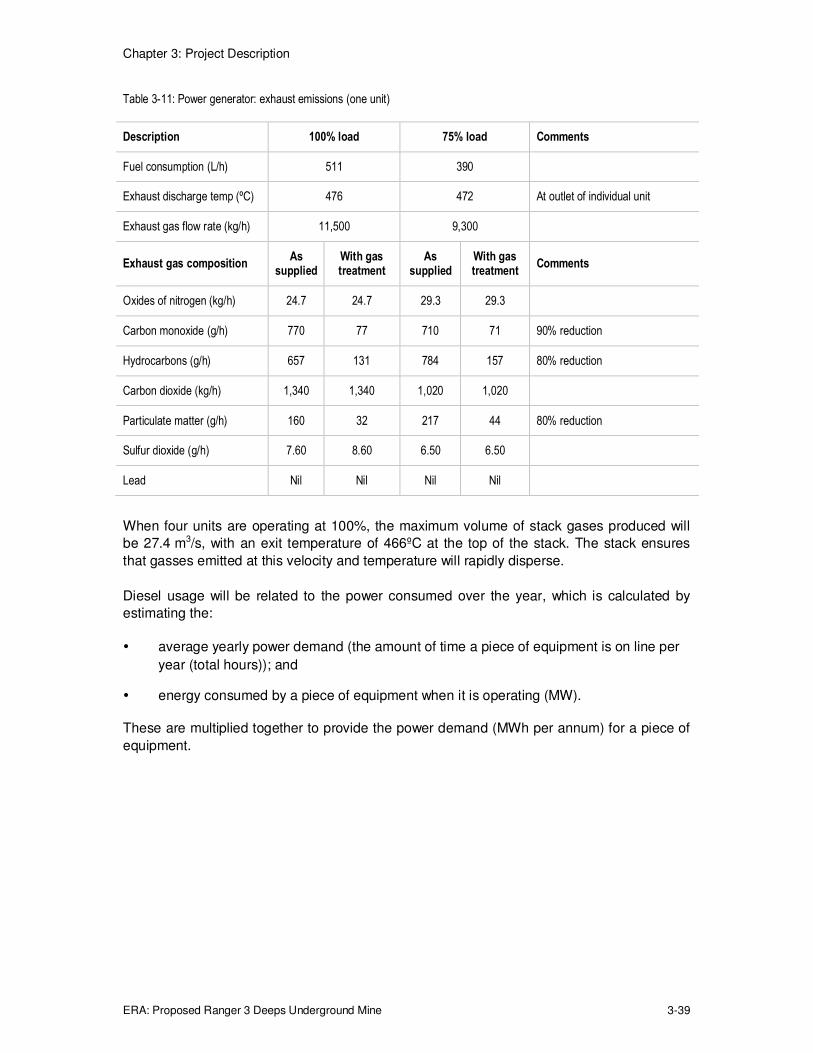
Chapter 3: Project Description
ERA: Proposed Ranger 3 Deeps Underground Mine 3-39
Table 3-11: Power generator: exhaust emissions (one unit)
Description 100% load 75% load Comments
Fuel consumption (L/h) 511 390
Exhaust discharge temp (ºC) 476 472 At outlet of individual unit
Exhaust gas flow rate (kg/h) 11,500 9,300
Exhaust gas composition As
supplied With gas treatment
As supplied
With gas treatment
Comments
Oxides of nitrogen (kg/h) 24.7 24.7 29.3 29.3
Carbon monoxide (g/h) 770 77 710 71 90% reduction
Hydrocarbons (g/h) 657 131 784 157 80% reduction
Carbon dioxide (kg/h) 1,340 1,340 1,020 1,020
Particulate matter (g/h) 160 32 217 44 80% reduction
Sulfur dioxide (g/h) 7.60 8.60 6.50 6.50
Lead Nil Nil Nil Nil
When four units are operating at 100%, the maximum volume of stack gases produced will
be 27.4 m3/s, with an exit temperature of 466ºC at the top of the stack. The stack ensures
that gasses emitted at this velocity and temperature will rapidly disperse.
Diesel usage will be related to the power consumed over the year, which is calculated by
estimating the:
� average yearly power demand (the amount of time a piece of equipment is on line per
year (total hours)); and
� energy consumed by a piece of equipment when it is operating (MW).
These are multiplied together to provide the power demand (MWh per annum) for a piece of
equipment.

Chapter 3: Project Description
ERA: Proposed Ranger 3 Deeps Underground Mine 3-40
Table 3-12 shows the average yearly power demand and associated diesel consumption for
the Project.
Table 3-12: Average yearly power demand and associated diesel consumption
2015 2016 2017 2018 2019 2020
Average yearly power demand (MW)
# 4.9 5.1 5.1 5 4.8
Diesel (kl/year) 2,520 10,728 11,208 11,148 10,998 10,608
# During construction power will be supplied by portable diesel generation sets - approximate diesel consumption is given.
3.5.3.3 Energy Efficiency
The underground mine will use modern equipment and operating philosophies to improve
energy efficiency.
The Project power plant output will be integrated with the brine concentrator power plant,
which will reduce the number of power generators needed for the Project by sharing the
back-up power generators.
Diesel-fuelled power generators, like any diesel engine, have a maximum efficiency range
and become inefficient when operated at very high or very low loads. By combining the two
power plants and sharing power supply across the wider network, the number of on line
power generators can be more easily adjusted to maintain operation within the maximum
efficiency range. This will reduce the amount of diesel consumed to supply the same amount
of electricity.
Where practical, electric motors for the underground mine (such as pumps and secondary
ventilation fans) will be high efficiency motors to reduce power demand.
Variable speed drives will be fitted to electric motors, where practical, to improve efficiency.16
For example, pumps in the underground mine will be driven by electric motors fitted with
variable speed drives where the flow of water from the pump is controlled by varying the
speed of the electric motor driving the pump. Except at full speed, this reduces the power
required to drive the pump. Similarly ventilation exhaust fans will be driven by electric motors
fitted with variable speed drives. The speed of individual exhaust fans is used to control the
airflow in different areas of the mine. Greater ventilation is used in areas where personnel
are working. Reduced ventilation is used to maintain safe air in areas where no one is
working. This operating philosophy means that electricity consumption can be reduced while
maintaining adequate ventilation for personnel working in the mine.
16 The alternate is "fixed speed drive", where a pump may run faster than is necessary for the quantity of fluid to be
pumped.
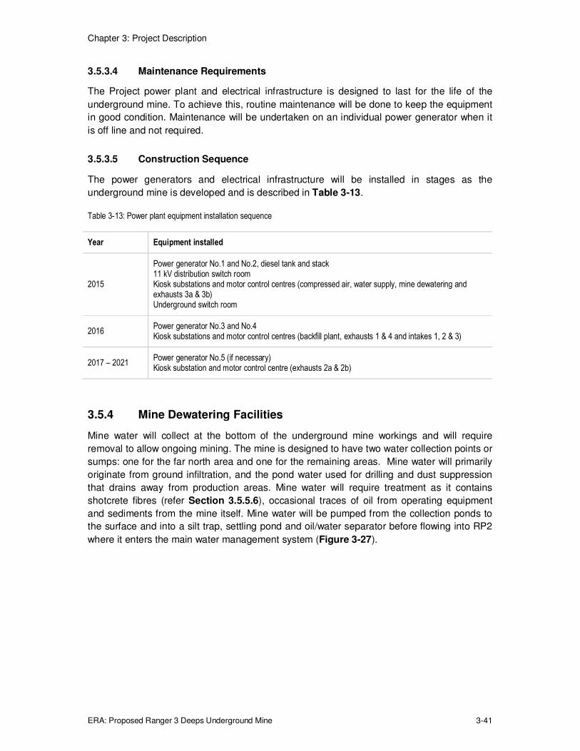
Chapter 3: Project Description
ERA: Proposed Ranger 3 Deeps Underground Mine 3-41
3.5.3.4 Maintenance Requirements
The Project power plant and electrical infrastructure is designed to last for the life of the
underground mine. To achieve this, routine maintenance will be done to keep the equipment
in good condition. Maintenance will be undertaken on an individual power generator when it
is off line and not required.
3.5.3.5 Construction Sequence
The power generators and electrical infrastructure will be installed in stages as the
underground mine is developed and is described in Table 3-13.
Table 3-13: Power plant equipment installation sequence
Year Equipment installed
2015
Power generator No.1 and No.2, diesel tank and stack 11 kV distribution switch room Kiosk substations and motor control centres (compressed air, water supply, mine dewatering and exhausts 3a & 3b) Underground switch room
2016 Power generator No.3 and No.4 Kiosk substations and motor control centres (backfill plant, exhausts 1 & 4 and intakes 1, 2 & 3)
2017 – 2021 Power generator No.5 (if necessary) Kiosk substation and motor control centre (exhausts 2a & 2b)
3.5.4 Mine Dewatering Facilities
Mine water will collect at the bottom of the underground mine workings and will require
removal to allow ongoing mining. The mine is designed to have two water collection points or
sumps: one for the far north area and one for the remaining areas. Mine water will primarily
originate from ground infiltration, and the pond water used for drilling and dust suppression
that drains away from production areas. Mine water will require treatment as it contains
shotcrete fibres (refer Section 3.5.5.6), occasional traces of oil from operating equipment
and sediments from the mine itself. Mine water will be pumped from the collection ponds to
the surface and into a silt trap, settling pond and oil/water separator before flowing into RP2
where it enters the main water management system (Figure 3-27).

Chapter 3: Project Description
ERA: Proposed Ranger 3 Deeps Underground Mine 3-42
Figure 3-27: Schematic flow diagram of the mine dewatering system
3.5.4.1 Mechanical and Operational Characteristics
Mine water will collect at the bottom of the underground mine in a sump from where it will be
pumped into an underground tank fitted with a screen to remove any oversized material,
including plastic shotcrete fibres. This material will be periodically collected and disposed of
in Pit 3. Mine water from the underground tank will be pumped to the surface via one or two
steel rising main/s in cased borehole/s. The current design deploys two piston diaphragm
pumps and a single rising main with a combined maximum pumping capacity of 150 L/s.
Further design studies will determine whether the design capacity is overly conservative and
whether to use one or two rising mains is required.
The mine water will be discharged from the rising main/s via double walled polyethylene
pipes into a silt trap where the bulk of the solids will settle in the bottom with the aid of a
flocculant which will cause solid particles to aggregate and settle. The silt trap will overflow
into a larger settling pond where the finer particles will settle. Settled solids will be removed
from the trap and pond with a front-end loader and deposited in the current operations
tailings storage facility (scheduled to be Pit 3).
Clarified mine water will overflow from the settling pond into an oil/water separator, where oil
floating on the water will be collected and discharged into containers for disposal. The solids-
and oil-free water will be pumped, or gravity fed, to RP2. The mine dewatering system will
operate continuously, with short duration stops for maintenance.
The combined silt trap, settling pond and oil/water separator arrangement (Item 12,
Figure 3-16) is approximately 65 m long, 25 m wide and is conceptually illustrated in
Figure 3-28.

Chapter 3: Project Description
ERA: Proposed Ranger 3 Deeps Underground Mine 3-43
An automated control system will be used to run the mine dewatering system to maximise
safety for the operators and to help stop spills. Features of the system include electronic
start-up and shutdown functions to ensure sumps, tanks and ponds do not overflow. Any
spills will drain to RP2.
Figure 3-28: Indicative image of the silt traps, settling ponds and oil/water separators
The silt trap and settling pond will be constructed on site from waste rock and will have a
shotcrete, or similar, lining. Groundwater collecting in and pumped from the underground
mine to the settling pond will be classified as pond water (refer Section 3.7.2) and does not
require elaborate leak protection since it is relatively good quality water which is low in
solutes.
3.5.4.2 Maintenance Requirements
The equipment in the mine dewatering system is designed to last for the life of the
underground mine. To achieve this, routine maintenance will be done to keep the equipment
in good condition.
3.5.5 Supporting Infrastructure
Supporting infrastructure for the underground mine includes:
� diesel supply and storage;
� water supply;
� compressed air;
� reticulation of materials and power;
� explosives storage;
� shotcrete transfer station;
Flocculant
Silt trap
Settling pond
Oil/water
separator
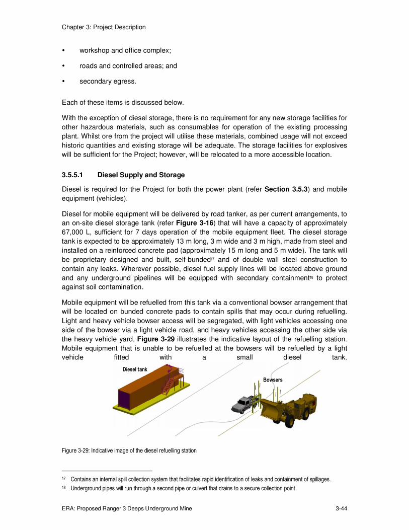
Chapter 3: Project Description
ERA: Proposed Ranger 3 Deeps Underground Mine 3-44
� workshop and office complex;
� roads and controlled areas; and
� secondary egress.
Each of these items is discussed below.
With the exception of diesel storage, there is no requirement for any new storage facilities for
other hazardous materials, such as consumables for operation of the existing processing
plant. Whilst ore from the project will utilise these materials, combined usage will not exceed
historic quantities and existing storage will be adequate. The storage facilities for explosives
will be sufficient for the Project; however, will be relocated to a more accessible location.
3.5.5.1 Diesel Supply and Storage
Diesel is required for the Project for both the power plant (refer Section 3.5.3) and mobile
equipment (vehicles).
Diesel for mobile equipment will be delivered by road tanker, as per current arrangements, to
an on-site diesel storage tank (refer Figure 3-16) that will have a capacity of approximately
67,000 L, sufficient for 7 days operation of the mobile equipment fleet. The diesel storage
tank is expected to be approximately 13 m long, 3 m wide and 3 m high, made from steel and
installed on a reinforced concrete pad (approximately 15 m long and 5 m wide). The tank will
be proprietary designed and built, self-bunded17 and of double wall steel construction to
contain any leaks. Wherever possible, diesel fuel supply lines will be located above ground
and any underground pipelines will be equipped with secondary containment18 to protect
against soil contamination.
Mobile equipment will be refuelled from this tank via a conventional bowser arrangement that
will be located on bunded concrete pads to contain spills that may occur during refuelling.
Light and heavy vehicle bowser access will be segregated, with light vehicles accessing one
side of the bowser via a light vehicle road, and heavy vehicles accessing the other side via
the heavy vehicle yard. Figure 3-29 illustrates the indicative layout of the refuelling station.
Mobile equipment that is unable to be refuelled at the bowsers will be refuelled by a light
vehicle fitted with a small diesel tank.
Figure 3-29: Indicative image of the diesel refuelling station
17 Contains an internal spill collection system that facilitates rapid identification of leaks and containment of spillages.
18 Underground pipes will run through a second pipe or culvert that drains to a secure collection point.
Bowsers
Diesel tank

Chapter 3: Project Description
ERA: Proposed Ranger 3 Deeps Underground Mine 3-45
The diesel storage tank and bowsers (diesel refuelling station) will have an automated
control system and safety features similar to those found at a residential service station. This
will include features such as an automatic shut off to prevent overfilling the vehicle’s fuel
tank.
3.5.5.2 Water Supply
Potable water and pond water are required for the Project. The different water classes used
at Ranger mine are discussed in Section 2.6.5.
Potable water
Potable water will be supplied from the existing site system into a new storage tank located
at the Project office complex. From here, water will be pumped to various locations for use,
including safety showers, eye wash stations and the office complex.
The poly propylene storage tank will have a capacity of approximately 30,000 L and will be
approximately 3.7 m in diameter and 3 m high. The storage tank will sit on a reinforced
concrete pad approximately 7.5 m long and 7.5 m wide.
Based on two, 12 hour shifts, with an underground shift crew of 65 and 10 daytime office
personnel, potable water usage is estimated to be 17,000 L per day. This assumes:
� all underground personnel (130 in total) take a shower daily;
� clothing for all 130 underground personnel is laundered daily;
� toilet usage by all personnel;
� drinking water is supplied to all personnel.
All grey water is planned to drain to a modern, standalone and self-contained sewage
treatment system at the office complex. Sewage sludge will be processed in the existing
Ranger sludge disposal area. If found to be cost effective, grey water may be pumped
directly to the Ranger main site sewage network.
Pond water
Pond water is required in the underground mine primarily for drilling equipment and dust
suppression. This water will be sourced from RP2 and pumped into two new storage tanks
(Item 13, Figure 3-16). Sodium hypochlorite diluted in water (the equivalent of domestic
bleach) will be dosed into these tanks to reduce the growth of potentially harmful biological
species such as bacteria and algae. From here, the water will be pumped into the
underground mine (Figure 3-30). As the pond water descends into the underground mine, its
pressure increases. This will be controlled by underground pressure reduction stations.
The two polypropylene storage tanks will have a total capacity of approximately 80,000 L,
and will be approximately 4.5 m in diameter and 3 m high. The storage tanks will sit on a
reinforced concrete pad, approximately 13 m long and 7.5 m wide and graded so that it
drains into the stormwater collection system in the unlikely event of a spill.
The automated control system for the mine will be used to maintain water pressure in the
reticulation piping. The system will also ensure that the tanks do not overflow during filling.

Chapter 3: Project Description
ERA: Proposed Ranger 3 Deeps Underground Mine 3-46
The sodium hypochlorite system adjacent to the tanks will sit on a bunded concrete pad to
contain any spilled liquor.
Figure 3-30: Schematic flow diagram of the potable and pond water systems
3.5.5.3 Compressed Air
The compressed air system will provide pressurised air to the underground mine for
shotcrete spraying (refer Section 3.5.5.6 for details of shotcrete) and the operation of mining
machines.
The air compressor will be delivered to Ranger mine as a complete package and will include
two air accumulators (that provide surge capacity and stabilise the compressor): one located
with the compressor on the surface, the other underground. The air compressor and
accumulator will be located on a concrete pad and will occupy an area approximately 10 m
long and 10 m wide. The accumulator will be the tallest component of the facility at 4 m.
The air compressor will be fitted with insulation to reduce noise, if necessary. The Atlas
Copco G250-10 (50 Hz) or equivalent will be used. These units generate 77 dBA as
measured according to ISO 2151:2004 using ISO 9614/2.
The air compressor is shown on the location map in Figure 3-16 (Item 13). An indicative
image of the air compressor and surface air accumulator is shown in Figure 3-31.
Figure 3-31: Indicative image of the air compressor and surface air accumulator
Surface air
accumulator
Air compressors

Chapter 3: Project Description
ERA: Proposed Ranger 3 Deeps Underground Mine 3-47
3.5.5.4 Reticulation of Materials and Power
This section discusses the methods used to reticulate various materials and power between
surface infrastructure and underground equipment. This includes: tailings; backfill discharge
water and slimes; backfill; mine water (from underground); pond water; potable water;
compressed air; electric power cables; and control system wiring.
These materials and services are grouped according to the material of construction used for
their reticulation and are discussed below.
Mine water, pond water and potable water
These materials are typically pumped through polyethylene pipes that are arranged on the
ground on earth pathways. Pipe diameters will be commensurate with flow requirements and
will typically be 150 mm or less in diameter, with the main dewatering lines being up to
200 mm in diameter. A recessed concrete block will be intermittently placed over the top of
the pipes to secure them and prevent excessive movement. Where necessary (e.g. when
crossing a road), the pipes will be placed underground, in culverts, if required.
Tailings and backfill discharge water
The tailings and backfill discharge water pipes will be fully bunded to guard against potential
pipe failure and spillage. Polyethylene pipes will be laid in graded trenches with potential
leakage directed to the current operations tailings storage facility (scheduled to be Pit 3).
Sections near the plant areas and buried sections will be equipped with pipe-in-pipe
secondary containment with potential leakage also directed to Pit 3.
Compressed air
Compressed air will be transported through polyurethane pipes running parallel to the water
pipelines described above.
Electric power cables and control system wiring
Electric power will be distributed in sheathed, steel-wire armoured cables. Surface
infrastructure cables will be buried. Underground mine power cables will either be suspended
from supports or laid on cable trays on the shoulder of the decline, or fed through purpose-
bored cable holes.
Control system wiring will be distributed in sheathed, steel-wire armoured cables beside the
electrical cables.
3.5.5.5 Explosives Storage
The types of explosives used for blasting in the underground mine will be the same as those
that are currently used in the open cut mine, namely:
� packaged explosives;
� emulsion explosives; and
� detonators.

Chapter 3: Project Description
ERA: Proposed Ranger 3 Deeps Underground Mine 3-48
Emulsion explosives are a concentrated mixture of nitrate salts and fuel blends containing
oils and emulsifiers to produce a dispersion of nitrate salt solution droplets in a continuous
fuel blend phase. Explosive emulsions are water resistant, whereas packaged explosives
typically are not.
While ammonium nitrate – fuel oil solution has been used for blasting in the exploration
decline, the Project will use emulsion explosives as they are better suited to the variable
ground conditions in the mine.
Packaged explosives
The three existing packaged explosives storage buildings will be relocated to a new facility
on the north east side of Pit 3, which is closer to the underground mine portal. The new
facility will be in an isolated area and will consist of earth berms surrounding the buildings,
with obscured entrances for light vehicle access. The berms direct the force of a potential
explosion upwards rather than outwards.
Packaged explosives will be delivered to the underground mine by a specialist light vehicle
via the portal and decline.
Emulsion explosives
Emulsion explosives will be prepared in the existing plant at Ranger mine which requires
refurbishing prior to the commencement of the underground mine. The plant will be operated
by a contracting company experienced in explosives preparation.
Emulsion explosives will be delivered to the underground mine by a specialist light vehicle
via the portal and decline.
Detonators
The existing detonator storage building is located with the existing ANFO (ammonium nitrate
fuel oil solution) storage buildings. The detonator storage building will be relocated to the
new packaged explosives facility on the north east side of Pit 3, with the ANFO storage
buildings.
Detonators will be delivered to the underground mine by a specialist light vehicle via the
portal and decline.
3.5.5.6 Shotcrete Transfer Station
Shotcrete (concrete sprayed using compressed air) will be principally used in the
underground mine to stabilise wall and roof sections following excavation. Shotcrete is
reinforced with plastic fibres approximately 30 to 40 mm long, which removes the need to
use traditional reinforcing mesh and allows faster shotcrete application.
Shotcrete (the consistency of wet concrete without aggregate) will be produced in Jabiru and
delivered to site in a conventional concrete agitator truck. This truck will park on a pad and
discharge the shotcrete into another truck, which is an underground agitator truck that will be
used to deliver the shotcrete into the underground mine. This will ensure that the
conventional concrete agitator truck does not enter the site controlled area (Section 3.5.5.8).
This shotcrete transfer station is shown in Figure 3-16 (Item 11).

Chapter 3: Project Description
ERA: Proposed Ranger 3 Deeps Underground Mine 3-49
3.5.5.7 Office Complex
An office complex is required for the Project and will consist of the mine control room as well
as offices, change rooms, meals area, a laundry and ablutions (Figure 3-16, Item 17). The
complex will also contain the potable water tank and self-contained sewerage treatment
system.
The office complex will be a mixture of new and existing buildings, and will be modular with
connecting covered walkways. The complex will measure approximately 100 m by 60 m.
Light vehicle and heavy vehicle parking areas will also be provided.
The existing maintenance workshop (Figure 3-16) will be used to service the equipment from
the underground mine. A new shed will be constructed in the existing workshop laydown yard
to be used as a store. The store will be approximately 15 m long by 10 m wide and 7 m high.
An indicative image of the office complex is provided in Figure 3-32.
Figure 3-32: Indicative image of the office complex
3.5.5.8 Roads
Roads at the Ranger mine are classified as either heavy vehicle roads or light vehicle roads.
Both road types will be used for the Project, as shown in Figure 3-2.
Heavy vehicle roads will be used to transport run of mine ore and waste rock from the portal
of the underground mine to the existing mill and storage areas. These are typically about
12.5 m wide, unsealed, gravel roads. Heavy vehicle roads around the portal are one-way to
form a loop with the heavy vehicle parking area. This reduces the likelihood of heavy
vehicles crossing paths. Light vehicles can also use the heavy vehicle roads.
Light vehicle roads are used by light vehicles to access surface infrastructure. These are
typically 7 – 9 m wide, unsealed, gravel roads. Heavy vehicles are not permitted to use the
light vehicle roads.
Heavy and light vehicle roads are graded so that rain water drains off the roads and into the
stormwater collection system.
Store
Meals
area
Office
Mine
control
room Heavy vehicle
parking
Potable water Sewerage
Walkway
Ablutions
Office Laundry Offices
Ablutions
Change
rooms
Change
rooms
Light vehicle
parking

Chapter 3: Project Description
ERA: Proposed Ranger 3 Deeps Underground Mine 3-50
The underground mine is within the Ranger mine site controlled area. This delineation is
used to separate vehicles that travel on site and underground from those that travel on and
off site, e.g. the shotcrete delivery truck. A light vehicle wash station and heavy vehicle wash
station are provided so that vehicles can be washed before passing from the controlled area
to a supervised area. Contaminated water collected from the vehicle wash bays will be sent
for treatment to the silt traps, settling ponds and oil separators of the mine dewatering
system.
Road pavement material for both construction and periodic maintenance will be sourced from
non-mineralised waste rock from the Ranger site, crushed and graded to specification. Haul
roads, light vehicle roads and access tracks will be constructed, where necessary, and
maintained using a haul truck, front end loader, grader, water cart and roller compactor. This
equipment is available on site at present, and is deemed to be adequate for the Project
requirements. Regular road maintenance will be carried out throughout the Project to
maintain the roads in good operating condition.
3.5.5.9 Secondary Egress
A secondary means of egress will be available in the event the portal/decline is blocked and
personnel need to leave the mine. This egress system will be installed at ventilation intake 3.
The system will consist of a torpedo or cage which can be winched to the surface. The winch
will have an emergency generator to supply it with power should site power be unavailable. A
typical egress hoist system is illustrated in Figure 3-33.
Figure 3-33: A typical egress hoist system19
The torpedo and winch system will be supplemented with a system of plastic egress ladders
installed in selected air intakes between development levels of the mine.
19 Images courtesy of Macmahon, www.macmahon.com.au

Chapter 3: Project Description
ERA: Proposed Ranger 3 Deeps Underground Mine 3-51
3.5.5.10 Plant Lighting
Plant lighting will be designed to provide a safe level of illumination of work areas while
minimising light spill into surrounding natural areas. However, where there is potential for
lighting to impact on the community or on native fauna populations, directional lighting will be
installed to minimise lighting disturbance.
3.5.5.11 Communications
Telecommunications systems for new infrastructure will connect to the existing Ranger mine
systems. No new communications towers will be required.
Several systems are used for emergency communication in the underground mine. These
include radio communications and an emergency notification system (also called a stench
gas system) in the event that radio communications are not possible. The emergency
notification system will be used if a situation arises where personnel must seek safety in a
refuge station (safe area of the mine). This system releases a benign gas into each
ventilation intake that gives the air an odour that can be quickly detected by all underground
workers. The odour indicates to personnel that they need to proceed to a refuge station.
When the situation is safe, personnel travel to the surface under the escort of the mine
rescue crew, if required.
3.5.6 Construction
The major equipment such as refrigeration components, power generators, substations,
tanks, bins, etc. will be pre-assembled units manufactured off site. This will reduce the
amount of construction at the Ranger mine site. The pre-assembled units will be transported
to Ranger mine by trucks and some of these may require traffic control on the highways.
Final assembly of major components and construction of smaller components (e.g. ductwork)
will be completed on site.
Site works will follow a common sequence
1. Levelling and earthworks to prepare the site for construction.
2. Completion of civil works where required (e.g. earth walls, bunds, trenches, drains,
etc.)
3. Pouring of concrete foundations for the major equipment and buildings.
4. Installing the major equipment pre-assembled units.
5. Building the structures to house the major equipment.
6. Installing the minor equipment, pipes and electrical equipment.
7. Testing and commissioning all equipment for service.
While the new infrastructure is being built, underground mine development will rely upon a
number of existing Ranger mine facilities. For example, underground water will be
processed by the existing mine water management system and power will be sourced from
the existing diesel generators that supply the exploration decline.
Chapter 3: Project Description
ERA: Proposed Ranger 3 Deeps Underground Mine 3-52
3.6 TRANSPORT
3.6.1 Primary Corridors
The primary transport routes to and from Ranger mine are discussed in Section 2.2.6 and
comprise the Arnhem and Kakadu Highways via the Stuart Highway. Both routes are used to
move freight, goods and services to and from the remote towns, pastoral properties, mines
and tourist destinations within the region.
The Project will utilise the existing road networks to transport the site consumables detailed
in Table 3-6 (Section 3.4.2) and uranium oxide product. The consumables and uranium
oxide product have been transported to and from Ranger mine since open cut mining began
in 1980 and no significant change is anticipated upon the commencement of the Project. A
detailed review of transportation impacts is presented in Chapter 12.
3.6.2 Access Tracks
Independent, all weather access tracks will be constructed to each item of infrastructure for
undertaking repairs and maintenance. These tracks will be approximately 6.5 m wide and
constructed on previously disturbed ground either within the existing infrastructure area or
the operational area between the main mine access road and the edge of Pit 3. Pavement
material for both construction and periodic maintenance will be sourced from non-mineralised
waste rock from the Ranger site, crushed and graded to specification. Regular maintenance
will be carried out throughout the Project to maintain access tracks in good operating
condition.
3.7 WATER MANAGEMENT
The Ranger 3 Deeps water management system will utilise the current Ranger water
management system. New groundwater management facilities will be built for dewatering
and treating groundwater from the underground mine, but once the treated water is delivered
to RP2 it will be managed using the existing water management infrastructure, processes
and procedures.
The existing water management strategy is described in Section 2.6.5. Potential
groundwater and surface water impacts related to the Project are discussed in Section 8.4
and Section 8.5.
Four classes of water are managed at Ranger mine, namely:
� pond water (runoff from active mining areas);
� process water (from the uranium extraction circuit);
� potable water (drinking/ablution); and
� managed release water (high quality runoff, or treated water suitable for release).
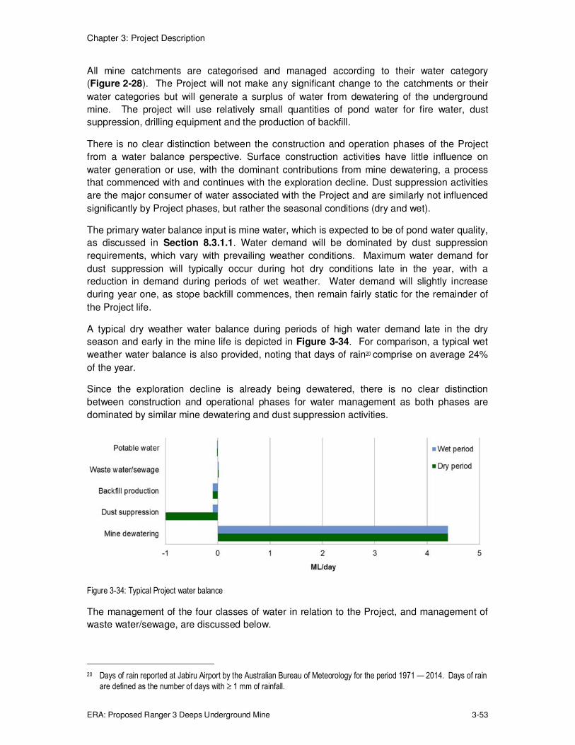
Chapter 3: Project Description
ERA: Proposed Ranger 3 Deeps Underground Mine 3-53
All mine catchments are categorised and managed according to their water category
(Figure 2-28). The Project will not make any significant change to the catchments or their
water categories but will generate a surplus of water from dewatering of the underground
mine. The project will use relatively small quantities of pond water for fire water, dust
suppression, drilling equipment and the production of backfill.
There is no clear distinction between the construction and operation phases of the Project
from a water balance perspective. Surface construction activities have little influence on
water generation or use, with the dominant contributions from mine dewatering, a process
that commenced with and continues with the exploration decline. Dust suppression activities
are the major consumer of water associated with the Project and are similarly not influenced
significantly by Project phases, but rather the seasonal conditions (dry and wet).
The primary water balance input is mine water, which is expected to be of pond water quality,
as discussed in Section 8.3.1.1. Water demand will be dominated by dust suppression
requirements, which vary with prevailing weather conditions. Maximum water demand for
dust suppression will typically occur during hot dry conditions late in the year, with a
reduction in demand during periods of wet weather. Water demand will slightly increase
during year one, as stope backfill commences, then remain fairly static for the remainder of
the Project life.
A typical dry weather water balance during periods of high water demand late in the dry
season and early in the mine life is depicted in Figure 3-34. For comparison, a typical wet
weather water balance is also provided, noting that days of rain20 comprise on average 24%
of the year.
Since the exploration decline is already being dewatered, there is no clear distinction
between construction and operational phases for water management as both phases are
dominated by similar mine dewatering and dust suppression activities.
Figure 3-34: Typical Project water balance
The management of the four classes of water in relation to the Project, and management of
waste water/sewage, are discussed below.
20 Days of rain reported at Jabiru Airport by the Australian Bureau of Meteorology for the period 1971 — 2014. Days of rain
are defined as the number of days with ≥ 1 mm of rainfall.

Chapter 3: Project Description
ERA: Proposed Ranger 3 Deeps Underground Mine 3-54
3.7.1 Process Water
The Project will utilise the existing processing facilities to process underground ore and the
process water circuit will remain unchanged. Process water will continue to be recycled in the
process plant and managed via treatment in the brine concentrator. The purified water
(distillate) from the brine concentrator will be released via managed release sites during the
wet season. The process water system is discussed in further detail in Section 2.6.5. Water
within the backfill plant and tailings dewatering plant will be classed as process water.
3.7.2 Pond Water
Pond water comes from rainfall that falls on the active mine site catchments, generating
water of a quality that requires management.
Surface water runoff from the Project surface facilities west of the main mine access road
and underground mine water will be classed and treated as pond water. Mine water will
collect at the bottom of the underground mine and be pumped to the surface, into a silt trap,
settling pond and oil/water separator before flowing into RP2 (refer Section 3.5.4) from
where it is recycled for other mine uses. The quantity of mine water produced will vary
during the mine life but will peak in 2016/17 at an average of 4.4 ML/day with a peak rate of
6.4ML/day. The impact of the additional pond water generated from the underground mine is
discussed in Chapter 8.
3.7.2.1 Fire Water System
The existing fire water system has sufficient capacity to protect new Project infrastructure.
Therefore no substantial change is planned to the existing fire water system other than
extending fire water services to the new infrastructure.
3.7.2.2 Drilling and Dust Suppression
Pond water is used above ground for dust suppression on haulage routes and stockpiles and
underground for dust suppression and drilling. Pond water used underground will be treated
to reduce the growth of potentially harmful biological organisms (refer Section 3.5.5.2).
The only significant point of pond water consumption for the Project will be dust suppression
on roads and the tramp metal station. It is estimated that up to about 1 ML/day of pond
water will be used for dust suppression in the dry season. Water trucks will apply up to
2 L/m2/hr to the 3.3 ha of gravel roads in the operational areas of the Project to achieve Level
2 control efficiency (75% dust reduction). Water sprays will also be used to suppress dust at
the tramp metal facility. The actual amount of water applied will vary with seasonal conditions
and time of day.
3.7.2.3 Backfill Production
Water is a component in backfill and is mixed with cement, aggregate and filtered tailings to
form a paste. It is estimated that approximately 0.1 ML/day of make-up water will be required
for backfill production.
Chapter 3: Project Description
ERA: Proposed Ranger 3 Deeps Underground Mine 3-55
3.7.3 Potable Water
The existing potable water system has sufficient capacity to supply the Project and potable
water will be reticulated along a common services corridor to service the Project as outlined
in Section 3.5.5.2. It is estimated that the Project will consume up to approximately
17 KL/day of potable water.
3.7.4 Managed Release water
Most stormwater falls on catchments that do not come into contact with mineralised rock or
tailings. The runoff is high quality water that does not require treatment and may leave the
site as stormwater runoff. These waters are closely monitored as an integral part of statutory
and operational management to ensure that water quality objectives are met in Magela
Creek.
Additional managed release water will be generated by increased treated pond water
originating from the Project. However, it will be of the same quality as existing managed
release water and the existing system has the capacity to manage the additional water.
Further details are provided in Chapter 8.
Surface water management and sediment control for the Project surface facilities, roads and
tracks will be integrated into the overall Ranger project planning and design.
3.7.5 Waste Water and Sewerage
The Project office complex is currently planned to be serviced by a self-contained sewage
treatment system. Approximately 14 KL/day of waste water will be generated by the Project.
Sewage sludge will be processed using the existing Ranger sludge disposal procedures. If
further investigation indicates grey water may be pumped directly to the Ranger main site
sewage network in a cost effective manner, then an alternative may be to use the existing
system. The current system has sufficient capacity to service the increased workforce.

Chapter 3: Project Description
ERA: Proposed Ranger 3 Deeps Underground Mine 3-56
3.8 WASTE MANAGEMENT
3.8.1 Mineralised Waste
The mineralised waste streams from the Project are very similar to the current operations.
Ranger 3 Deeps ore will be processed through the existing processing plant as described in
Chapter 2. The total amount of material entering the mill (ore from the underground mine
and from existing stockpiles) will remain similar to the feed quantity for the existing
operations. Consequently, tailings production is expected to remain at similar levels to that
currently produced. The composition of the waste materials is not significantly different from
the current scheduled Pit 3 waste rock and tailings (refer Section 3.4.1 for further details).
A significant change from the current operations will be the use of tailings and low grade
(Category 2) ore as components in the production of mine backfill (refer Section 3.5.1).
Approximately 400,000 t/yr of tailings21 and a similar quantity of aggregate (crushed low
grade rock) will be used for backfill production to fill the mined out stopes in the underground
mine. This will result in a net reduction of 2 Mt of above ground tailings disposal when
compared to the operations in the absence of the Project.
A small quantity of high carbonate reject material will be generated from the ore-sorter. This
material is classified as waste rock (<0.02 wt% U3O8; <0.03 wt% sulfur) and will be stockpiled
and managed as described in Section 2.6.2 and Section 2.6.3. Waste rock is suitable for
capping material or forming the final landform surface. This material is expected to be higher
in carbonate and of very low uranium content so will be preferentially used as good quality
road base material for underground operations.
An indicative mass balance of mined materials and mineralised wastes scheduled to be
returned to the underground in the form of backfill and to Pit 3 in the form of tailings is
diagrammatically shown in Figure 3-35.
3.8.2 Non-mineralised Waste
The Project will generate non-mineralised wastes equivalent to the existing operations. The
waste streams generated by the existing operations and disposal routes for each waste
stream are illustrated in Figure 3-36.
21 Tailings generated from processing a blend of underground ore and stockpiled open pit ore.

Chapter 3: Project Description
ERA: Proposed Ranger 3 Deeps Underground Mine 3-57
Figure 3-35: Indicative materials balance for Ranger 3 Deeps underground mine

Chapter 3: Project Description
ERA: Proposed Ranger 3 Deeps Underground Mine 3-58
Figure 3-36: Waste classification – existing operations and the Project
Dis
po
sal
Was
te S
tream
WASTE
MANAGEMENT
Primary weathered and lateritic material
Tailings Scrap steel Plastic/poly
pipes Process residue
Equipment Heavy
machinery Rubber (tyres, conveyor belts,
liners) Wood
Radioactive contaminated hydrocarbons
(waste oil, blackjack,
degreaser, rags and absorbents)
Small quantities packaged process residues
Scrap steel (small items)
Empty drums
Hydrocarbon contaminated
soils
Hazardous and redundant chemicals
Asbestos
Lead batteries
Waste oil
Paper Cardboard
Plastic Aluminium cans
Printer cartridges
Wood Glass
Domestic (crib room) waste Construction
waste Air filters
Bulky bags
Non-hazardous Hazardous
Mineral Non-mineral
Stockpile & backfill
production
Tailings dam, Pit 3 & backfill
production
On-site radioactive
Incineration On-site
landfill trench Recycling
On-site landfill trench
Off-site disposal
Recycling Bioremediation
Non- metalliferous
Metalliferous Radiation
contaminated Non-
radioactive

Chapter 3: Project Description
ERA: Proposed Ranger 3 Deeps Underground Mine 3-59
3.9 PROJECT SCHEDULE AND WORKFORCE
3.9.1 Project Schedule
An indicative development and closure schedule is presented in Figure 3-37.
Ranger 3 Deeps key activities
2015 2016 2017 2018 2019 2020
Q1 Q2 Q3 Q4 Q1 Q2 Q3 Q4 Q1 Q2 Q3 Q4 Q1 Q2 Q3 Q4 Q1 Q2 Q3 Q4 Q1 Q2 Q3 Q4
Construction
EIS approval
Site establishment
Road construction
Backfill plant
Mine ventilation (Ex 3a)
Mine ventilation (Ex 1, Ex 3b, Ex 4, In 1,In 2, In 3, Portal)
Mine ventilation (Ex 2a, Ex 2b)
Power plant (phase 1)1
Power plant (phase 2)2
Power plant (phase 3)3
Mine dewatering
Supporting infrastructure
Mining
Decline development
Lateral development
Ventilation shafts
Stoping
Backfill of stopes
Closure and Rehabilitation
Ranger 3 Deeps key activities
2021 2022 2023 2024 2025 2026
Decline, vent shaft backfill
Surface rehabilitation and revegetation In accordance with whole of site closure plan
Figure 3-37: Indicative Ranger 3 Deeps development schedule

Chapter 3: Project Description
ERA: Proposed Ranger 3 Deeps Underground Mine 3-60
Construction will occur over the first 2 years. The early stages of mine development will
focus on installing lateral access and the mine ventilation system, with ore removal ramping
up in 2016 and then continuing until 2020.
The mining activity (lateral development and stoping) will occur concurrently in each of the
targeted area of the resource (mining districts identified in Figure 3-9) as this enables
maximum material recovery and production rates within the authorised period.
Closure of the stoping areas will occur progressively with the mining development, as
described in Section 3.3.3. Backfill of the decline and ventilation shafts will occur
immediately after cessation of the mining activity, and is anticipated to require 8 months. The
bottom of each shaft will be "plugged", as will the decline at the base of the weathered zone,
and then filled with cemented paste comprising milled waste rock. Surface rehabilitation,
landform design and revegetation will proceed in accordance with, as a small component of
whole of site closure, as discussed in Section 3.10 and Chapter 11.
The closure schedule for current Ranger operations is discussed in Section 13.2.1.
3.9.2 Workforce
Project construction and operations will require between 180 and 280 new employees over
the life of the operation.22
A contract workforce will construct the new facilities over a two-year period, with completion
anticipated early in 2017. During operations, 10 employees will be required to run the new
surface facilities.
The underground mine will operate continuously, 7 days per week for the entire year, on a
roster of two, 12 hour shifts per day. The underground workforce will be predominantly a
contract workforce and will ramp up over a two-year period, peaking in 2017 at around 295
employees. For production positions requiring full coverage, four crews are required. The
estimate assumes each employee will be entitled to 28 days of annual leave. The
underground workforce requirements and skills base required are summarised in Table 3-14.
The majority of the new workforce will require specialised skills in underground mining and
will be supplied from both local and interstate sources.
There will be some redeployment of the existing workforce to the Project so the total number
of employees is not indicative of the number of new jobs.
The net impact of the Project on the workforce requirements (comparing with existing
operations) is provided in Table 3-15 and Figure 3-38.
The closure and rehabilitation workforce for the Ranger mine is not affected by the Project.
22 Excludes the ramp up during 2015 where workforce numbers are highly sensitive to the Project start-up date and cannot
be reasonably predicted at this stage.

Chapter 3: Project Description
ERA: Proposed Ranger 3 Deeps Underground Mine 3-61
Table 3-14: Ranger 3 Deeps underground employees
Position Position type 2015 2016 2017 2018 2019 2020
Owner workforce
Owner staff Management 1 1 1 1 1 1
Supervisory 2 2 2 2 2 2
Engineering/technical 29 29 29 29 23 21
Administrative 1 1 1 1 1 1
Total owner workforce 33 33 33 33 27 25
Contract workforce
Contract staff Management 6 6 6 6 6 6
Engineering/technical 8 9 9 8 7 7
Supervisory 13 15 15 14 14 14
Administrative 2 3 3 3 2 2
Sub-total 29 33 33 31 29 29
Contract operators Tradesman 34 38 38 38 38 38
Operator 124 172 191 181 158 130
Sub-total 158 210 229 219 196 168
Total contract workforce 187 243 262 250 225 197
Total project workforce 220 276 295 283 252 222
Table 3-15: Workforce requirements – Project and existing operations
Year
Existing operations Project
New jobs generated by the Project
Darwin based staff
Ranger processing plant and operations
Closure and rehabilitation activities
Surface infrastructure (construction and operation)
Underground mine
development and operation
2015 50 320 96 66 80 146 #
2016 50 320 96 51 221 272
2017 50 320 90 17 236 253
2018 50 320 68 10 226 236
2019 50 320 66 10 202 212
2020 50 320 79 10 178 188
# The peak 2015 workforce during the Project ramp up is highly sensitive to the Project start-up date and cannot be accurately predicted at this stage

Chapter 3: Project Description
ERA: Proposed Ranger 3 Deeps Underground Mine 3-62
Figure 3-38: Combined workforce – Ranger 3 Deeps and existing operations
3.9.3 Accommodation Requirements
ERA has a range of existing accommodation options for the operations workforce and for
personnel working on construction projects. All construction and operations employees can
be accommodated in existing facilities, so no new accommodation will be required for the
Project.
Short‐term employees, permanent fly-in/fly-out employees and the contractor workforce will
generally be accommodated in ERA's contractor camps, although in some cases commercial
tourist accommodation (hotels and lodges) may be used. Permanent site-based employees
will be housed in company housing in Jabiru. A number of staff members will remain as
Darwin based employees. Fly-in/fly-out employees will utilise ERA contracted commercial air
transport services between Darwin and Jabiru airports. It is anticipated that approximately
300 return flights will be required per annum for the Project. Bus transport will convey
employees between Jabiru airport Ranger mine, the contractor camps and Jabiru township.
Accommodation requirements over the life of the Project are displayed in Figure 3-39.
0
100
200
300
400
500
600
700
800
2015 2016 2017 2018 2019 2020
Closure and rehabilitation activities Ranger processing plant and operations Darwin based staff
Project underground developmentand operation
Project surface infrastructure(construction and operation)

Chapter 3: Project Description
ERA: Proposed Ranger 3 Deeps Underground Mine 3-63
Figure 3-39: Combined (existing and Project) workforce accommodation
3.10 CLOSURE AND REHABILITATION
The Ranger Authorisation states the overall rehabilitation goal requires ERA to:
"… rehabilitate the Ranger project area to establish an environment similar to the adjacent
areas of Kakadu National Park such that, in the opinion of the Commonwealth Minister with
the advice of the Supervising Scientist, the rehabilitated area could be incorporated into
Kakadu National Park."
A closure strategy for the Project has been developed that aligns with the closure planning
for the current Ranger mine operations. Following approval of the Project, this strategy will
be integrated into the overall Ranger closure plan.
Details on closure and rehabilitation are outlined in Chapter 13 but are briefly summarised
below.
3.10.1 Final Landform Design
The conceptual approach for the design of the final landform at Ranger mine is to recreate,
as far as practicable, a landscape with features similar to those of the surrounding area.
ERA has developed a revegetation strategy to establish plant communities that are similar to
the surrounding Kakadu National Park.
The Project will have little impact on the overall landform design, since the vast majority of
works are underground and the use of backfill will prevent ground subsidence. The decline
0
100
200
300
400
500
600
700
800
2015 2016 2017 2018 2019 2020
Darwin based staff Jabiru residential employees Camp accomodation: fly-in/fly-out employees

Chapter 3: Project Description
ERA: Proposed Ranger 3 Deeps Underground Mine 3-64
will be backfilled to ground level and all surface exploration, ventilation shafts and paste
delivery holes will be grouted to prevent surface water entry or access by wildlife.
3.10.2 Infrastructure Decommissioning
At the end of life for the underground mine, the site infrastructure will be demolished. The
current closure schedule has the following steps:
1. The plant will be emptied of all materials (tailings, aggregate, cement, oils, refrigerant
gases, cooling water),
2. Waste materials will be recycled or disposed in an appropriate manner
a. Mineral wastes will be deposited in Pit 3,
b. Diesel, oils, greases, refrigerant gases will be either recycled or disposed in an
approved manner using approved contractors.
c. Waste water will be managed via the existing water management system
d. Hazardous materials will be collected and disposed in an approved manner using
approved contractors.
3. All sources of power will be disconnected (electrical, hydraulic, pneumatic) to make the
equipment safe.
4. The plant will be deconstructed and deposited in Pit 3.
5. Power generators, kiosk substations and switchgear will be decontaminated and sold.
6. Concrete pads will be deconstructed and deposited in Pit 3.
3.10.3 Rehabilitation Techniques and Revegetation Program
The objective for revegetation of the current operations is outlined in the Ranger
Authorisation:
"Revegetate the disturbed sites of the Ranger project area using local native plant
species similar in density and abundance to those existing in adjacent areas of Kakadu
National Park, to form an ecosystem the long term viability of which would not require a
maintenance regime significantly different from that appropriate to adjacent areas of
the Park."
To achieve this objective ERA will:
� use locally-sourced native plant species.
� establish vegetation that can exhibit sustained growth and development;
� restore functional ecosystems with characteristics of sustainability, resistance and
resilience to disturbance, and habitat values that are consistent with, and can be
integrated into the surrounding landscape.

Chapter 3: Project Description
ERA: Proposed Ranger 3 Deeps Underground Mine 3-65
At the completion of operations surface infrastructure installed as part of the Project will be
removed and the area revegetated. Infrastructure includes the backfill plant, fans, pumps,
pipelines, water management ponds and the electrical reticulation system. Underground vent
infrastructure will be retrieved as backfilling advances or buried in situ. Disturbed areas will
be re-contoured along with existing site disturbed areas and revegetation will progress
accordance with the overall Ranger revegetation strategy.
ERA’s revegetation strategy is underpinned by an understanding of both general ecological
principles and ecosystem dynamics in northern Australia, and also based on the knowledge
gained through 30 years of revegetation trials and research.
The general aim of revegetation is to first establish the framework species. These are long
lived native trees and shrubs which in a natural ecosystem control much of a site’s nutrient
and water resources, dominate the canopy, provide habitat for other flora and fauna species,
and have a high contribution to ecosystem functioning and stability. Once framework species
are established, other species will colonize the site, provided it is within reasonable proximity
to other vegetation. Introduction of an understorey is delayed to allow framework species to
establish without competition and to decrease the impacts of fire.
Chapter 13 provides further detail on the strategy adopted to achieve the rehabilitation
objective.
3.10.4 Solute Transport from Tailings and Waste Rock
The predicted long term transport of solutes through groundwater to Magela Creek from the
disposal of tailings and waste rock for the Project is discussed in Chapter 13. The solute
transport modelling concluded that leaching from Ranger 3 Deeps backfill materials will be
negligible, and there will be no change to the predicted solute transport from Pit 3 closure.
3.10.5 Post Closure Monitoring
The Project will be incorporated into the more substantial closure plan for Ranger mine and
will not require any closure criteria parameters specific to Ranger 3 Deeps. Post closure
monitoring will be completed as part of the Ranger mine closure plan.
3.10.6 Staging and Timing
Detailed studies to support the decommissioning phase of the existing operations,
particularly the mined out Pits 1 and 3, have already commenced and decommissioning is
already underway with the backfilling of these open pits. Other areas are scheduled for
rehabilitation and decommissioning as soon as they become available. Facilities and
services required for decommissioning and rehabilitation works will not be removed until the
relevant works are complete. Water and waste management facilities will be among the last
of the facilities to be decommissioned and until then, potable and industrial water supplies
will be maintained for site use. Decommissioning will ramp up at the completion of
processing plant operations by January 2021 and will continue to 2026.
Related Documents