3-i CHAPTER 3. MARKET AND TECHNOLOGY ASSESSMENT TABLE OF CONTENTS 3.1 INTRODUCTION .............................................................................................................. 3-1 3.2 MARKET ASSESSMENT ................................................................................................. 3-3 3.2.1 Trade Association ................................................................................................... 3-3 3.2.2 Manufacturers and Market Share ............................................................................ 3-3 3.2.2.1 Small Businesses...................................................................................... 3-5 3.2.3 Regulatory Programs .............................................................................................. 3-5 3.2.3.1 Natural Resources Canada ....................................................................... 3-6 3.2.3.2 Australia and New Zealand...................................................................... 3-7 3.2.4 Non-Regulatory Initiatives...................................................................................... 3-7 3.2.4.1 ENERGY STAR ...................................................................................... 3-7 3.2.4.1 Federal Energy Management Program (FEMP) ...................................... 3-8 3.2.4.2 Consortium for Energy Efficiency ........................................................... 3-9 3.2.4.3 Rebate Programs .................................................................................... 3-10 3.2.5 Equipment Classes ................................................................................................ 3-11 3.2.6 Shipments and Available Equipment .................................................................... 3-12 3.2.6.1 Air-Conditioning, Heating, and Refrigeration Institute Data ................ 3-12 3.2.6.2 North American Association of Food Equipment Manufacturers Data. 3-13 3.2.6.3 Census Bureau Data ............................................................................... 3-14 3.2.7 Equipment Lifetimes ............................................................................................. 3-14 3.3 TECHNOLOGY ASSESSMENT..................................................................................... 3-15 3.3.1 Baseline Equipment Components and Operation ................................................. 3-15 3.3.1.1 Basic Equipment Description and Components .................................... 3-15 3.3.1.2 Batch Process ......................................................................................... 3-17 3.3.1.3 Continuous Process ................................................................................ 3-22 3.3.2 Technology Options .............................................................................................. 3-24 3.3.2.1 Compressor ............................................................................................ 3-25 3.3.2.2 Condenser .............................................................................................. 3-27 3.3.2.3 Higher Efficiency Condenser Fans and Fan Motors .............................. 3-28 3.3.2.4 Improved Auger Motor Efficiency ........................................................ 3-28 3.3.2.5 Improved Pump Motor Efficiency ......................................................... 3-29 3.3.2.6 Evaporator .............................................................................................. 3-29 3.3.2.7 Improved or Thicker Insulation ............................................................. 3-30 3.3.2.8 Larger Diameter Suction Line (Remote Compressor Models) .............. 3-30 3.3.2.9 Reduced Potable Water Flow................................................................. 3-30 3.3.2.10 Drain Water Thermal Exchange ............................................................ 3-31 3.3.3 Energy Use Data ................................................................................................... 3-31 REFERENCES .......................................................................................................................... 3-38

Welcome message from author
This document is posted to help you gain knowledge. Please leave a comment to let me know what you think about it! Share it to your friends and learn new things together.
Transcript

3-i
CHAPTER 3. MARKET AND TECHNOLOGY ASSESSMENT
TABLE OF CONTENTS 3.1 INTRODUCTION .............................................................................................................. 3-1 3.2 MARKET ASSESSMENT ................................................................................................. 3-3
3.2.1 Trade Association ................................................................................................... 3-3 3.2.2 Manufacturers and Market Share ............................................................................ 3-3
3.2.2.1 Small Businesses ...................................................................................... 3-5 3.2.3 Regulatory Programs .............................................................................................. 3-5
3.2.3.1 Natural Resources Canada ....................................................................... 3-6 3.2.3.2 Australia and New Zealand ...................................................................... 3-7
3.2.4 Non-Regulatory Initiatives...................................................................................... 3-7 3.2.4.1 ENERGY STAR ...................................................................................... 3-7 3.2.4.1 Federal Energy Management Program (FEMP) ...................................... 3-8 3.2.4.2 Consortium for Energy Efficiency ........................................................... 3-9 3.2.4.3 Rebate Programs .................................................................................... 3-10
3.2.5 Equipment Classes ................................................................................................ 3-11 3.2.6 Shipments and Available Equipment .................................................................... 3-12
3.2.6.1 Air-Conditioning, Heating, and Refrigeration Institute Data ................ 3-12 3.2.6.2 North American Association of Food Equipment Manufacturers Data. 3-13 3.2.6.3 Census Bureau Data ............................................................................... 3-14
3.2.7 Equipment Lifetimes ............................................................................................. 3-14 3.3 TECHNOLOGY ASSESSMENT ..................................................................................... 3-15
3.3.1 Baseline Equipment Components and Operation ................................................. 3-15 3.3.1.1 Basic Equipment Description and Components .................................... 3-15 3.3.1.2 Batch Process ......................................................................................... 3-17 3.3.1.3 Continuous Process ................................................................................ 3-22
3.3.2 Technology Options .............................................................................................. 3-24 3.3.2.1 Compressor ............................................................................................ 3-25 3.3.2.2 Condenser .............................................................................................. 3-27 3.3.2.3 Higher Efficiency Condenser Fans and Fan Motors .............................. 3-28 3.3.2.4 Improved Auger Motor Efficiency ........................................................ 3-28 3.3.2.5 Improved Pump Motor Efficiency ......................................................... 3-29 3.3.2.6 Evaporator .............................................................................................. 3-29 3.3.2.7 Improved or Thicker Insulation ............................................................. 3-30 3.3.2.8 Larger Diameter Suction Line (Remote Compressor Models) .............. 3-30 3.3.2.9 Reduced Potable Water Flow................................................................. 3-30 3.3.2.10 Drain Water Thermal Exchange ............................................................ 3-31
3.3.3 Energy Use Data ................................................................................................... 3-31 REFERENCES .......................................................................................................................... 3-38

3-ii
LIST OF TABLES Table 3.2.1 NRCan Efficiency Standard for Continuous Automatic Commercial Ice Makers ... 3-6 Table 3.2.2 ENERGY STAR Automatic Commercial Ice Maker Key Criteria* ........................ 3-8 Table 3.2.3 Performance Requirements for Federal Purchases of Air-Cooled Ice Makers ......... 3-8 Table 3.2.4 Performance Requirement for Federal Purchases of Water-Cooled Ice Makers ...... 3-9 Table 3.2.5 CEE Efficiency Requirements for Air-Cooled Ice Makers .................................... 3-10 Table 3.2.6 CEE Efficiency Requirements for Water-Cooled Ice Makers ................................ 3-10 Table 3.2.7 Automatic Commercial Ice-Making Equipment Classes........................................ 3-12 Table 3.2.8 AHRI 2010 Shipments of Automatic Commercial Ice Makers, by Equipment Class 3-
13 Table 3.2.9 NAFEM Ice Maker Category Cross Reference with DOE Equipment Classes ..... 3-14 Table 3.2.10 Census Bureau Automatic Commercial Ice Maker Shipments ............................ 3-14 Table 3.2.11 Estimates for Automatic Commercial Ice Maker Lifetimes ................................. 3-15 Table 3.3.1 Brief Description of Primary Refrigeration System Components .......................... 3-17 Table 3.3.2 Batch Evaporator Designs ...................................................................................... 3-19 Table 3.3.3 Technology Options for Automatic Commercial Ice Makers ................................ 3-25 Table 3.3.4 Compressor Rating Conditions (oF (oC))................................................................ 3-26
LIST OF FIGURES
Figure 3.2.1 Domestic Refrigerated Display Case Market Shares as of 1996 ............................. 3-4 Figure 3.3.1 Typical Vapor Compression Refrigeration Cycle for Batch Type Ice Makers ..... 3-18 Figure 3.3.2 Cracked Ice Forming on “Cracked Ice” Evaporators ............................................ 3-20 Figure 3.3.3 Water System Diagram for Batch Type Ice Makers ............................................. 3-21 Figure 3.3.4 Typical Vapor Compression Refrigeration Cycle for Continuous Ice Makers ..... 3-23 Figure 3.3.5 Cross-Section of Continuous Evaporator and Auger ............................................ 3-24 Figure 3.3.6 Energy Consumption vs. Harvest Rate (Air-Cooled Cube Ice-Making Heads) .... 3-32 Figure 3.3.7 Energy Consumption vs. Harvest Rate (Water-Cooled Batch Ice-Making Heads) .. 3-
33 Figure 3.3.8 Energy Consumption vs. Harvest Rate (Air-Cooled Cube Remote Condensing
Units).................................................................................................................. 3-33 Figure 3.3.9 Energy Consumption vs. Harvest Rate (Air-Cooled Non-Cube-Batch Remote
Condensing Units) ............................................................................................. 3-34 Figure 3.3.10 Energy Consumption vs. Harvest Rate (Air-Cooled Cube Self-Contained Units) . 3-
34 Figure 3.3.11 Energy Consumption vs. Harvest Rate (Water-Cooled Cube Self-Contained Units)
............................................................................................................................ 3-35 Figure 3.3.12 Energy Consumption vs. Harvest Rate (Air-Cooled Flake/Nugget Ice-Making
Heads) ................................................................................................................ 3-35 Figure 3.3.13 Energy Consumption vs. Harvest Rate (Water-Cooled Flake/Nugget Ice-Making
Heads) ................................................................................................................ 3-36 Figure 3.3.14 Energy Consumption vs. Harvest Rate (Air-Cooled Flake/Nugget Remote
Condensing Units) ............................................................................................. 3-36 Figure 3.3.15 Energy Consumption vs. Harvest Rate (Air-Cooled Flake/Nugget Self-Contained
Units).................................................................................................................. 3-37

3-iii
Figure 3.3.16 Energy Consumption vs. Harvest Rate (Water-Cooled Flake/Nugget Self-Contained Units) ................................................................................................ 3-37

3-1
CHAPTER 3. MARKET AND TECHNOLOGY ASSESSMENT
3.1 INTRODUCTION
This chapter details the market and technology assessment that the U.S. Department of Energy (DOE) has conducted in support of the ongoing energy conservation standards rulemaking for automatic commercial ice makers, including self-contained ice makers with air or water cooling; ice-making heads with air or water cooling; remote condensing and remote compressor ice makers; and remote condensing (but not remote compressor) ice makers. Automatic commercial ice makers produce a range of ice types, including cube type ice, flake ice, nugget ice, tube type ice, and cracked or fragmented ice. The Energy Policy and Conservation Act (EPCA) prescribes energy conservation standards for automatic commercial ice makers that produce cube type ice with capacities between 50 and 2,500 pounds of ice per 24-hour period.a (42 U.S.C. 6313(d)(1)) Review of these standards is required by EPCA prior to January 1, 2015. (42 U.S.C. 6313(d)(3)) DOE is also proposing, under 42 U.S.C. 6313(d)(2), standards for other types of ice makers and equipment with capacities up to 4,000 lb/24 hours.
This chapter consists of a market and technology assessment. The purpose of the market assessment is to develop a qualitative and quantitative characterization of the automatic commercial ice-making (ACIM) equipment industry and market structure based on publicly available information and information submitted by manufacturers and other stakeholders. Manufacturer characteristics and market shares, existing regulatory and non-regulatory efficiency improvement initiatives, equipment classes, and trends in markets and equipment characteristics are addressed. The purpose of the technology assessment is to develop a preliminary list of technologies that could improve the efficiency of automatic commercial ice makers.
Automatic commercial ice makers are used in several types of commercial sectors, including health care, lodging, foodservice, retail, education, food sales, and office buildings.
Definitions
EPCA defines “automatic commercial ice maker” as a factory-made assembly (not necessarily shipped in one package) that:
1. consists of a condensing unit and ice-making section operating as an integrated unit, with means for making and harvesting ice; and
2. may include means for storing ice, dispensing ice, or storing and dispensing ice. (42 U.S.C. 6311(19))
The Energy Policy Act of 2005 (EPACT 2005) set energy and condenser water usage standards for cube type icemakers capable of producing between 50 and 2,500 lb/24 hours, and added the definition given above to EPCA. EPACT 2005 further established standards for automatic commercial ice makers that produce cube type ice based on: (1) the configuration of
a Pounds of ice per 24-hour period is abbreviated herein as lb/24 hours.

3-2
the ice-making and refrigeration systems; (2) the type of cooling media used; and (3) the capacity of the unit.
Accordingly, the main categories of equipment covered under this rulemaking are as follows.
1. Self-contained automatic commercial ice makers: A self-contained automatic commercial ice maker is a category in which the ice-making machinery, including freezing, harvesting, and condensing components, and storage compartment, are in an integral cabinet. Self-contained automatic commercial ice makers tend to have lower harvest capacity, are typically used in office buildings and retail applications, and are generally designed to fit under counters.
2. Ice-Making Head: An ice-making head is a category in which the ice-making machinery, including freezing, harvesting, and condensing components, is integrated into one unit that does not include a means for storing ice. Ice-making heads are generally mounted on top of separately sold storage bins.
3. Remote Condensing Ice Makers: For automatic commercial ice makers, two remote condensing configurations exist. In one configuration, the compressor is contained within the same cabinet as the ice freezing and harvesting equipment, while the condenser is located in a separate package. This configuration is referred to in this rulemaking as “remote condensing (but not remote compressor).” In the other configuration, the compressor is located remotely from the cabinet containing the ice freezing and harvesting equipment, typically with the condenser in a remote condensing unit. This configuration can also be designed for connection to an existing remote compressor rack and is referred to as “remote condensing and remote compressor” in this rulemaking. Remote condensing units are typically larger ice makers, with harvest capacities up to 4,000 lb/24 hours for commercial ice makers.
In addition to the foregoing categories of ice-making equipment, self-contained units and ice-making heads are also categorized by the means used for disposing of the heat extracted from water when making ice.
1. Air Cooled: Ice makers are referred to as air cooled if the waste heat from the condenser is released directly into the air.
2. Water Cooled: Ice makers are referred to as water cooled if the heat removed from potable water during the ice-making process is rejected into water in the condenser. Ice makers can be attached to closed cooling-water loops that recirculate and reuse the same cooling water or can be installed with open-loop (or single-pass) cooling systems that use water one time for cooling and then release it into the wastewater system.
Most remote condensing ice makers feature air-cooled condensers, and the EPCA ACIM efficiency standards apply specifically to air-cooled equipment. DOE notes that at least one remote condensing ice maker features a water-cooled condenser.

3-3
The third differentiating factor within the equipment configuration and cooling type is the harvest capacity of a given ice maker. Harvest capacity is defined in terms of the amount of ice an ice maker can produce in 24 hours.
3.2 MARKET ASSESSMENT
The following market assessment identifies the manufacturer trade association, domestic manufacturers of automatic commercial ice makers, manufacturer market share, regulatory programs, and non-regulatory initiatives; defines equipment classes; provides historical shipment data, shipment projections, and equipment lifetime estimates; and summarizes market performance data.
3.2.1 Trade Association
The Air-Conditioning, Heating, and Refrigeration Institute (AHRI, formerly the Air-Conditioning and Refrigeration Institute, or ARI, and the Gas Appliance Manufacturers Association, or GAMA) is the most prominent trade association for automatic commercial ice maker manufacturers. AHRI coordinated with member manufacturers to establish the Automatic Commercial Ice Makers and Ice Storage Bins division within AHRI. This division serves to develop standards and implement a certification program for automatic commercial ice makers and storage bins.
The technical activities of AHRI include:
• working to harmonize international equipment standards; • developing industry performance standards for automatic commercial ice makers; • updating industry guidelines for operation and installation of ACIM equipment; • communicating with refrigerant suppliers and government agencies about
environmentally acceptable refrigerants; and, • providing input to government agencies concerning regulations affecting the industry.
3.2.2 Manufacturers and Market Share
Current members of AHRI’s Automatic Commercial Ice Makers and Ice Storage Bins division are listed below; parent companies are shown in parentheses if applicable.1
• Hoshizaki America, Inc. • IMI Cornelius, Inc. • ITV Ice Makers SA • KD Industries, Inc./Kold Draft (Erie Management Group, LLC) • Manitowoc Ice, Inc. (The Manitowoc Company, Inc.) • Mile High Equipment LLC/Ice-O-Matic (Scotsman Industries) • Scotsman Ice Systems (Scotsman Industries)

3-4
Other automatic commercial ice maker manufacturers are listed below; parent companies are shown in parentheses if applicable.
• A&V Refrigeration • Arctic-Temp/Holiday Ice, Inc. • Brema Ice Makers • Follett Ice Makers (VGI Holdings Corp) • Howe Corporation • North Star Ice • Orien U.S.A. • Summit Appliance (Felix Storch, Inc.) • Vogt Ice, LLC (Vogt Power International)
According to a recent study by Koeller & Company, the ice maker market is dominated by four manufacturers of automatic ice makers, who produce approximately 90 percent of the automatic commercial ice makers for sale in the United States.2 The four major manufacturers with the largest market share are Manitowoc (30 percent market share), Scotsman (25 percent), Hoshizaki (20 percent), and Mile High Equipment LLC/Ice-O-Matic (15 percent). See Figure 3.2.1. Koeller cited a 1996 report by Arthur D. Little, Inc.
Source: Koeller and Company, Potential Best Management Practices, June 2008.
Figure 3.2.1 Domestic Refrigerated Display Case Market Shares as of 1996
The landscape of the automatic commercial ice maker market has changed since this data was published in 1996. At about the same time that the data on Figure 3.2.1 was compiled, the parent company of Mile High Equipment LLC/Ice-O-Matic was acquired by Enodis, PLC. Enodis then acquired Scotsman industries in 1999.3 Thus, these two companies no longer existed as independent and separate entities.
Manitowoc 30%
Scotsman 25%
Hoshizaki 20%
Mile High Equipment LLC/Ice - O -
Matic 15%
IMI Cornelius and Others
10%

3-5
In 2008, Manitowoc agreed to purchase Enodis, PLC. At the time, Manitowoc was believed to control 40 percent of the market for cube-making machines, and Enodis controlled 30 percent. The Manitowoc purchase of Enodis, PLC would have concentrated a vast majority of automatic commercial ice maker production in the hands of one company. In a settlement agreement with the U.S. Justice Department, Manitowoc agreed to divest the U.S. ice machine business lines, including Ice-O-Matic and Scotsman. Manitowoc sold the ice machine business lines to Warburg Pincus Private Equity X, L.P., who announced they would use the Scotsman name.4,5 Thus, the ice-making companies have been consolidated since this data was collected. The three largest firms—Manitowoc, Scotsman/Ice-O-Matic, and Hoshizaki—are believed to continue to control approximately 90 percent of the market in the United States.
3.2.2.1 Small Businesses
DOE will consider the possibility that energy conservation standards for automatic commercial ice makers would adversely affect small businesses. The Small Business Administration (SBA) defines small business manufacturing enterprises for the commercial refrigeration equipment, in general, as those having 750 employees or fewer.6 SBA lists small business size standards for industries as they are described in the North American Industry Classification System (NAICS). The size standard for an industry is the largest that a for-profit concern can be in that industry and still qualify as a small business for Federal Government programs. These size standards are generally expressed in terms of the average annual receipts or the average employment of a firm. For commercial refrigeration equipment,b the size standard is matched to NAICS code 333415, Air-Conditioning and Warm Air Heating Equipment and Commercial and Industrial Refrigeration Equipment Manufacturing, and is 750 employees.
DOE will study the potential impacts on these small businesses in detail during the manufacturer impact analysis, which will be conducted as a part of the notice of proposed rulemaking (NOPR) analysis. As part of the NOPR for test procedures, DOE identified eight small business manufacturers of automatic commercial ice makers. 76 FR 18428 (April 4, 2011). DOE will perform a similar analysis for the energy conservation standards in the NOPR phase.
3.2.3 Regulatory Programs
Outside of the United States, Canada and Australia and New Zealand have efficiency standards for automatic commercial ice makers.
Within the United States, several states (Arizona, California, Oregon, and Washington) have established efficiency regulations for automatic commercial ice makers. The state standards all regulate cube type ice makers only. California’s standards were adopted in 2004, and were based on the Consortium for Energy Efficiency (CEE) Tier 1 and Federal guidelines for purchasing energy efficient equipment. The California standards also match those passed by the U.S. Congress as part of EPACT 2005. All other state standards were based on the California/EPACT 2005 standards, and became effective January 1, 2008. The state standards b Automatic commercial ice makers is a small component of the equipment manufacturing category, NAICS code 333415. This NAICS category covers a broad segment of heating, ventilation, and refrigeration equipment manufacturing including commercial refrigeration, commercial ice makers, heat pumps, air conditioners, warm air furnaces, air conditioners, and a number of other types of equipment and components.

3-6
have since been pre-empted by the Federal standards set forth in EPACT 2005 and effective January 1, 2010.
3.2.3.1 Natural Resources Canada
The Natural Resources Canada (NRCan) Office of Energy Efficiency established energy efficiency standards for automatic commercial ice makers on December 31, 1998. The NRCan standard covers all equipment between 23 and 1,000 kilograms per day (a kilogram equals roughly 2.2 lb), and covers not just batch ice but also continuous ice (flake and nugget). NRCan’s standard had a compliance date of January 1, 2008.
The NRCan standards are similar to the EPACT 2005 standards in that the covered batch equipment types are broken out into similar categories. However, NRCan standards cover additional equipment not covered by EPACT 2005 standards, including continuous type ice makers and batch type ice makers that produce other than cube type ice. The NRCan efficiency standards also establish minimum storage effectiveness levels for ice storage bins on self-contained ice makers. As noted in the preliminary technical support document (TSD) chapter 2, DOE is considering not regulating storage energy usage as part of this rulemaking.
Table 3.2.1 lists the NRCan equipment classes for continuous type automatic commercial ice makers, converted to units equivalent to those used in the current DOE cube type efficiency standard set by EPACT 2005. For batch process equipment, the NRCan standards are the same as those set by EPACT 2005 when units are converted to those used in the United States. As a result, Table 3.2.1 only shows continuous classes.
NRCan does not require adjustments of continuous ice maker usage for ice hardness. Nor does the continuous ice maker efficiency standard differentiate by the type of equipment (i.e., ice-making head, self-contained, units with remote condensing). The NRCan website indicates the continuous process efficiency standard went into effect January 1, 2000.
Table 3.2.1 NRCan Efficiency Standard for Continuous Automatic Commercial Ice Makers
Equipment Type Type of Cooling Ice-Making
Capacity lb/24 hours*
Maximum Energy Use kWh/100 lb**,***
All Continuous Machines Air < 660 ≥ 660
11.03 – 0.0064 x C 6.79
All Continuous Machines Water < 660 ≥ 660
9.33– 0.0051 x C 5.94
Source: NRCan website. * The NRCan standard expressed capacity in terms of kilograms per 24 hours. DOE converted this to lb/24 hours. ** The NRCan standard expressed energy usage in terms of kJ/kg (kilojoule per kilogram). DOE converted this to kWh/100 lb. *** The NRCan standard expressed C as capacity (ice harvest rate) in kilograms per 24 hours. DOE converted this to kWh/100 lb. www.oee.nrcan.gc.ca/regulations/product/automatic_ice_makers.cfm?attr=0

3-7
3.2.3.2 Australia and New Zealand
Australia and New Zealand have also established required efficiency standards for automatic commercial ice makers and storage bins.7 The minimum energy performance standards are established in Australian Standard AS/NZS 4865.3:2008 as maximum energy consumption per 100 kg of ice. The Australian standards categorize equipment by the following criteria:
• modular type ice makers, air cooled and water cooled (two size categories) • self-contained ice makers, air cooled and water cooled (two size categories) • split system, air-cooled, remote condensing but not remote compressor • split system, air-cooled, remote condensing and remote compressor • storage systems
The standards apply to cube, flake, and nugget machines without distinguishing between the machines and, apparently, without adjusting continuous ice maker energy usage for ice hardness. The Australian standards also establish a high efficiency rating, above their minimum standard classes.
3.2.4 Non-Regulatory Initiatives
DOE reviewed several voluntary programs promoting energy efficient automatic commercial ice makers in the United States, ENERGY STAR®, CEE, and the Federal Energy Management Program (FEMP) procurement program. DOE also reviewed various rebate programs offered by utilities.
3.2.4.1 ENERGY STAR
The ENERGY STAR standards issued by the U.S. Environmental Protection Agency (EPA) have been effective since January 1, 2008 and concern only cube type, air-cooled automatic ice machines. The level of performance corresponds with CEE’s Tier 2 for energy use. ENERGY STAR also sets a potable water use limit for all ice machines considered. ENERGY STAR plans to revisit their standard after the revision of the industry test procedures by AHRI and the American Society of Heating, Refrigerating and Air-Conditioning Engineers (ASHRAE) to include performance standards for flake and nugget machines.8 ENERGY STAR criteria are listed in Table 3.2.2.

3-8
Table 3.2.2 ENERGY STAR Automatic Commercial Ice Maker Key Criteria*
Equipment Type Harvest Rate, H lb/24 hours
Energy Use Limit kWh/100 lb ice
Potable Water Use Limit
gal/100 lb ice Air-Cooled
IMH <450 9.23 – 0.0077H <25 >450 6.20 – 0.0010H <25
RCU (without remote compressor)
<1,000 8.05 – 0.0035H <25 >1,000 4.64 <25
RCU (with remote compressor)
<934 8.05 – 0.0035H <25 >934 4.82 <25
SCU <175 16.7 – 0.0436H <35 >175 9.11 <35
kWh = kilowatt-hours *ENERGY STAR is currently developing new ice maker specifications. For more information, see www.energystar.gov/index.cfm?c=revisions.commercial_ice_machine_spec.
3.2.4.1 Federal Energy Management Program (FEMP)
FEMP is a program administered by DOE that oversees the Federal Government’s energy management and investment initiatives. FEMP has established purchasing specifications for energy efficient equipment, including cube type automatic commercial ice makers, which Federal agencies must follow when buying new equipment for their facilities.9 Federal purchasers are required by EPACT 2005 to purchase equipment that is either ENERGY STAR qualified or FEMP designated. The FEMP designated equipment consists of equipment that is in the upper 25 percent of energy efficiency in its class. Table 3.2.3 provides the requiremets for Federal purchase of air-cooled ice makers and Table 3.2.4 provides the requirements for water-cooled ice makers.10
Table 3.2.3 Performance Requirements for Federal Purchases of Air-Cooled Ice Makers Type Ice Harvest Rate
lb/24 hours Energy Consumption*
per 100 pounds Potable Water Use
per 100 pounds Ice Making Head ≤300 6.9 kWh or less 25 gallons or less Ice Making Head 301 – 449 5.7 kWh or less 25 gallons or less Ice Making Head 450 – 699 5.5 kWh or less 25 gallons or less Ice Making Head 700 – 999 5.2 kWh or less 25 gallons or less Ice Making Head 1,000 - 1,499 4.7 kWh or less 25 gallons or less Ice Making Head ≥1,500 4.6 kWh or less 25 gallons or less Self-Contained ≤75 13.6 kWh or less 35 gallons or less Self-Contained 76 – 174 9.3 kWh or less 35 gallons or less Self-Contained ≥175 9.1 kWh or less 35 gallons or less Remote Condensing ≤500 6.3 kWh or less 25 gallons or less Remote Condensing 501 – 699 5.6 kWh or less 25 gallons or less Remote Condensing 700 – 899 4.9 kWh or less 25 gallons or less Remote Condensing ≥900 4.6 kWh or less 25 gallons or less Source: DOE Federal Energy Management Program Covered Products website, www1.eere.energy.gov/femp/technologies/eep_purchasingspecs.html. * Measured in accordance with ARI Standard 810-2006, Performance Rating of Automatic Commercial Ice Makers.

3-9
Table 3.2.4 Performance Requirement for Federal Purchases of Water-Cooled Ice Makers Type Ice Harvest Rate
lb/24 hours Energy Use kWh/100 lb*
Self-Contained Unit ≤199 6.6 or less Self-Contained Unit ≥200 6.5 or less Ice Making Head ≤300 5.3 or less Ice Making Head 301 – 400 4.8 or less Ice Making Head 401 – 500 4.3 or less Ice Making Head 501 – 750 4.1 or less Ice Making Head 751 – 1,435 3.5 or less Ice Making Head ≥1,436 3.4 or less Source: DOE Federal Energy Management Program Covered Products website, www1.eere.energy.gov/femp/technologies/eep_purchasingspecs.html. * Measured in accordance with ARI Standard 810-2003, Performance Rating of Automatic Commercial/Ice Makers.
3.2.4.2 Consortium for Energy Efficiency
Between 2006 and July 2011, CEE used a three-tiered system to set efficiency requirements for cube type machines. CEE set Tier 1 to be equivalent to FEMP standards, most recently the FEMP standards effective as of January 1, 2010. CEE set Tier 2 to be 10 percent below Tier 1, and Tier 3 to be 15 percent below Tier 1. ENERGY STAR standards corresponded approximately with Tier 2 (for air-cooled machines). CEE standards set limits on both energy and water use. The water use is separated into potable water use and cooling water use for water-cooled machines.
Beginning on July 1, 2011, CEE revised their system, making the Tier 1 equal to the previous Tier 2 levels, and setting the new Tier 2 to 10 percent lower than Tier 1.11 The new CEE efficiency requirements for air-cooled ice makers are shown in Table 3.2.5, while the new requirements for water-cooled ice makers are shown in Table 3.2.6.

3-10
Table 3.2.5 CEE Efficiency Requirements for Air-Cooled Ice Makers
Level Corresponding
Base Specification
Equipment Type Ice Harvest Rate
(H) lb of ice/day
Energy Use Limit
kWh/100 lb of ice
Potable Water Use
Limit gal/100 lb of
ice
Tier 1
ENERGY STAR / Former CEE Tier 2 (pre-7/1/2011)
Cube Type Machines Only: Ice-Making Head
<450 9.23 - 0.0077H ≤25
≥450 6.20 - 0.0010H ≤25
Cube Type Machines Only: Remote- Condensing without remote compressor
<1,000 8.05 - 0.0035H ≤25
≥,1000 4.64 ≤25
Cube Type Machines Only: Remote- Condensing with remote compressor
<934 8.05 - 0.0035H ≤25
≥934 4.82 ≤25
Cube Type Machines Only: Self-Contained
<175 16.7 - 0.0436H ≤35 ≥175 9.11 ≤35
Tier 2
Approximately 10% More Efficient than Average Performance
Cube and Nugget Type Ice Machines
<175 14 – 0.0347H ≤30 ≥175 and <450 9.6 – 0.0098H ≤20
≥450 and <1,000 5.9 – 0.0016H ≤20 ≥1,000 4.5 – 0.0002H ≤20
Flake Type Ice Machines
<1,000 6.5 – 0.0033H ≤20 ≥1,000 3.2 ≤20
Source: CEE website, www.cee1.org/com/com-kit/com-kit-equip.php3.
Table 3.2.6 CEE Efficiency Requirements for Water-Cooled Ice Makers
Level Corresponding
Base Specification
Equipment Type Ice Harvest Rate
(H) lb of ice/day
Energy Use Limit
kWh/100 lb ice
Potable Water Use
Limit gal/100 lb of
ice
Tier 1 Former CEE Tier 2 (pre-7/1/2011)
Cube Type Machines Only: Ice-Making Head
<500 7.02 – 0.0049H ≤25 ≥500 and <1436 5.13 – 0.0010H ≤25
≥1436 3.68 ≤25 Cube Type Machines Only: Self-Contained
<200 10.6 – 0.0177H ≤35 ≥200 7.07 ≤35
Tier 2
Approximately 10% More Efficient than Average Performance
Cube and Nugget Type Ice Machines
<175 10.6 - 0.0241H ≤30 ≥175 and <450 7.1 - 0.0062H ≤20 ≥450 and <1000 4.7 - 0.0011H ≤20
≥1,000 3.7 - 0.0002H ≤20 Flake Type Ice Machines
<1,000 4.8 - 0.0017H ≤20 ≥1,000 3.1 ≤20
3.2.4.3 Rebate Programs
Numerous organizations and entities throughout the United States offer rebate programs for customers who purchase and install qualified automatic commercial ice makers. Twenty three utilities, governmental agencies, and other entities operate rebate programs specifically to provide incentives to customers who purchase ENERGY STAR compliant ice makers. The rebate programs, which can be found on the ENERGY STAR website by using the “Commercial

3-11
Food Service Equipment Incentive Finder,” offer rebates ranging from $50 to $600 for qualifying purchases.
The EnergySmart Grocer Program is funded by California utility ratepayers under the auspices of the California Public Utilities Commission. Eligible participants include grocery and convenience stores, food processors, and refrigerated warehouses operating in the Pacific Gas and Electric Company (PG&E) electric service territory. The program offers rebates for use of specific technologies on automatic commercial ice makers that are equivalent to CEE Tier 3 or ENERGY STAR.12
The New York State Energy Research and Development Authority (NYSERDA) offers rebates on pre-qualified commercial refrigeration equipment, including automatic commercial ice makers, ranging from $75 for smaller equipment meeting CEE Tier 2 specifications to $500 for large equipment meeting CEE Tier 3 specifications.13
3.2.5 Equipment Classes
Automatic commercial ice makers are divided into equipment classes categorized by physical characteristics that affect commercial application, equipment utility, and equipment efficiency: (1) the ice-making process; (2) the configuration of the ice-making and refrigeration systems; (3) the type of cooling media used; and (4) the capacity of the unit. The following list shows the key characteristics of automatic commercial ice makers that DOE is proposing to use for this rulemaking:
1. ice-making process • continuous • batch
2. equipment configuration • ice-making head • remote condensing
o remote condensing (but not remote compressor) o remote condensing and remote compressor
• self-contained
3. condenser cooling media • air-cooled • water-cooled
4. capacity range • various
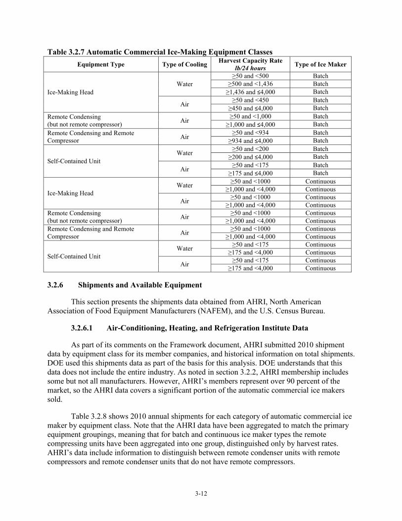
Table 3.2.7 shows the automatic commercial ice-making equipment classes DOE is considering within the scope of this rulemaking.
3-12
Table 3.2.7 Automatic Commercial Ice-Making Equipment Classes Equipment Type Type of Cooling Harvest Capacity Rate
lb/24 hours Type of Ice Maker
Ice-Making Head Water
≥50 and <500 Batch ≥500 and <1,436 Batch
≥1,436 and ≤4,000 Batch
Air ≥50 and <450 Batch ≥450 and ≤4,000 Batch
Remote Condensing (but not remote compressor) Air ≥50 and <1,000 Batch
≥1,000 and ≤4,000 Batch Remote Condensing and Remote Compressor Air ≥50 and <934 Batch
≥934 and ≤4,000 Batch
Self-Contained Unit Water ≥50 and <200 Batch
≥200 and ≤4,000 Batch
Air ≥50 and <175 Batch ≥175 and ≤4,000 Batch
Ice-Making Head Water ≥50 and <1000 Continuous
≥1,000 and <4,000 Continuous
Air ≥50 and <1000 Continuous ≥1,000 and <4,000 Continuous
Remote Condensing (but not remote compressor) Air ≥50 and <1000 Continuous
≥1,000 and <4,000 Continuous Remote Condensing and Remote Compressor Air ≥50 and <1000 Continuous
≥1,000 and <4,000 Continuous
Self-Contained Unit Water ≥50 and <175 Continuous
≥175 and <4,000 Continuous
Air ≥50 and <175 Continuous ≥175 and <4,000 Continuous
3.2.6 Shipments and Available Equipment
This section presents the shipments data obtained from AHRI, North American Association of Food Equipment Manufacturers (NAFEM), and the U.S. Census Bureau.
3.2.6.1 Air-Conditioning, Heating, and Refrigeration Institute Data
As part of its comments on the Framework document, AHRI submitted 2010 shipment data by equipment class for its member companies, and historical information on total shipments. DOE used this shipments data as part of the basis for this analysis. DOE understands that this data does not include the entire industry. As noted in section 3.2.2, AHRI membership includes some but not all manufacturers. However, AHRI’s members represent over 90 percent of the market, so the AHRI data covers a significant portion of the automatic commercial ice makers sold.
Table 3.2.8 shows 2010 annual shipments for each category of automatic commercial ice maker by equipment class. Note that the AHRI data have been aggregated to match the primary equipment groupings, meaning that for batch and continuous ice maker types the remote compressing units have been aggregated into one group, distinguished only by harvest rates. AHRI’s data include information to distinguish between remote condenser units with remote compressors and remote condenser units that do not have remote compressors.

3-13
Table 3.2.8 AHRI 2010 Shipments of Automatic Commercial Ice Makers, by Equipment Class
Type of Ice Maker Equipment Type
Type of Cooling
Harvest Capacity Rate lb/24 hours 2010 Shipments
Batch IMH Water ≥50 and <500 7,364 Batch IMH Water ≥500 and <1,436 4,734 Batch IMH Water ≥1,436 and ≤4,000 748 Batch IMH Air ≥50 and <450 43,913 Batch IMH Air ≥450 and ≤4,000 26,173 Batch RCU Air ≥50 and <1,000 8,804 Batch RCU Air ≥1,000 and ≤4,000 9,856 Batch SCU Water ≥50 and <200 1,101 Batch SCU Water ≥200 and ≤4,000 351 Batch SCU Air ≥50 and <175 22,468 Batch SCU Air ≥175 and ≤4,000 10,640 Continuous IMH Water ≥50 and <1000 1,265 Continuous IMH Water ≥1,000 and <4,000 123 Continuous IMH Air ≥50 and <1000 7,213 Continuous IMH Air ≥1,000 and <4,000 260 Continuous RCU Air ≥50 and <1000 1,972 Continuous RCU Air ≥1,000 and <4,000 773 Continuous SCU Water ≥50 and <175 - Continuous SCU Water ≥175 and <4,000 241 Continuous SCU Air ≥50 and <175 7,478 Continuous SCU Air ≥175 and <4,000 6,713
3.2.6.2 North American Association of Food Equipment Manufacturers Data
NAFEM publishes a biennial study of the foodservice equipment and supplies market. The latest available report is titled 2010 Size and Shape of the Industry Study.14 It contains survey data from NAFEM members (not all members provided data for the report), including shipments numbers and the value of sales in dollars. Based on the numbers reported by the respondents to the survey, NAFEM developed a total market estimate of shipments (units shipped and dollar sales) for the year 2009. NAFEM published similar study reports for shipments in 200815 and 2006.16
The “refrigeration and ice machine study” is part of the NAFEM reports and includes shipments data for cube, flake, and nugget ice makers as well as ice dispensers—both manual fill and integrated systems. Table 3.2.9 shows the DOE equipment classes to which the NAFEM equipment corresponds. Due to the aggregation of the NAFEM data, it provided additional data for putting total shipments into context, but not for identifying the relative shares of shipments by equipment class. Shipment estimates have been withheld from publication because the NAFEM reports are not publicly available.

3-14
Table 3.2.9 NAFEM Ice Maker Category Cross Reference with DOE Equipment Classes NAFEM Category DOE Equipment Class
Cube Ice Makers Batch Flake Ice Makers Continuous Nugget Ice Makers Continuous Ice Dispenser, Integrated Systems Self-Contained Units Ice Dispenser, Manual Fill –
3.2.6.3 Census Bureau Data
The U.S. Census Bureau’s Current Industrial Report (CIR) series publishes statistics on the quantity and value of shipments based on a survey of manufacturers. The CIR has been published since 1904, and DOE collected CIR data going back to the 1940s for purposes of evaluating prices and shipments.
Table 3.2.10 shows shipment data for ice-making machines.
Table 3.2.10 Census Bureau Automatic Commercial Ice Maker Shipments Product Description Year Quantity Value Companies
Self-contained ice-cube makers, automatic, under 200 lb
2010 42,293 43,039 4 2009 61,699 55,522
Self-contained ice-cube makers, automatic, 200 lb and over
2010 (not reported) 102,696 5 2009 (not reported) 84,524
Self-contained flake or chip machines, 300 lb and under
2010 (not reported) (not reported) 3 2009 546 1,369
Self-contained flake or chip machines, over 300 lb 2010 21,368 50,728 6 2009 17,958 42,016
Ice-making machines, not self-contained 2010 107,723 258,408 7 2009 94,876 217,791
Ice-making machines, combination ice makers and ice/drink dispensers
2010 74,635 181,612 5 2009 62,367 150,330
Source: U.S. Census Bureau, Current Industrial Reports, 2010. www.census.gov/manufacturing/cir/historical_data/ma333m/index.html
Automatic commercial ice makers are treated in U.S. Census Bureau data series as part of NAICS 333415. In general, automatic commercial ice makers are such a small piece of NAICS 333415 that the U.S. Census Bureau does not report them separately in any table reviewed by the DOE, except for the CIR tables.
In summary, although the U.S. Census Bureau data contain some limited shipments data that would be useful for conducting technical analyses, not enough detail is available to provide specific assessments for shipments within each of the primary categories covered in this rulemaking.
3.2.7 Equipment Lifetimes
DOE reviewed available literature and consulted with experts on automatic commercial ice makers to establish typical equipment lifetimes. The literature and individuals consulted estimated a fairly narrow and consistent range of typical equipment lifetimes, shown in Table

3-15
3.2.11. Most references cited in the table appear to have derived the underlying data for their estimates of equipment lifetime from the 1996 Arthur D. Little report.17
Individuals with experience in the manufacture or distribution of automatic commercial ice makers suggested a typical case life of 7 to 10 years, with some equipment being retired after as short a period as 5 years in cases of building remodels and as long as 20 years in cases where the equipment owners did not care about the appearance of the equipment.
Some literature suggested lifetimes of up to 20 years or more for tube type automatic commercial ice makers.
Table 3.2.11 Estimates for Automatic Commercial Ice Maker Lifetimes Life Reference
7 to 10 years Arthur D. Little, 199617 8.5 years California Energy Commission, 200418 8.5 years Fernstrom, G., 200419 8.5 years Koeller J., and H. Hoffman, 20082 7 to 10 years Navigant Consulting, Inc. 200920
3.3 TECHNOLOGY ASSESSMENT
This section provides a technology assessment for automatic commercial ice makers. Contained in this technology assessment are details about product operations and components (section 3.3.1), an examination of possible technological improvements for each product (section 3.3.2), and a characterization of the product efficiency levels currently available on the market (section 3.3.3).
3.3.1 Baseline Equipment Components and Operation
This section briefly describes the components and operation of automatic commercial ice makers (referred to within this section as “ice makers”). These descriptions provide a basis for understanding the technologies used to improve product efficiency.
3.3.1.1 Basic Equipment Description and Components
A typical ice maker consists of a refrigeration system and a water supply system contained within an insulated case. The ice makers may or may not have an integrated storage bin. Ice makers that have no integral storage bin generally deliver ice by gravity (i.e., dropping the ice) into a bin or other equipment, such as a beverage/ice dispenser, on which the ice maker is mounted when in use. The refrigeration system may be entirely contained in a single unit, or the condenser and possibly the compressor may be located remotely.
Ice makers are classified into three categories, as discussed in section 3.2.5: ice-making heads (IMHs), remote condensing units (RCUs), and self-contained units (SCUs). IMHs have the highest sales levels and are available in the widest range of capacities. They are generally mounted on top of a separate storage bin or other equipment that uses the ice. The indoor sections of RCUs are similar to IMHs, except that they are mated with remote condensers intended to be located outdoors, rejecting heat directly to the outside air without adding to the interior air-conditioning load. SCUs have their own integral ice storage bins. They generally

3-16
have smaller harvest capacities than IMHs and RCUs, and most of these units are designed for under-counter placement.
There are two distinct ice-making processes that are used by commercial ice makers:
• The batch process involves alternate freezing and harvesting periods, producing batches of solid ice by allowing water to flow over an evaporator and freeze into cubes, tubes, or another shape depending on the evaporator geometry. Once the ice is fully formed, the refrigeration system switches into harvest mode, in which compressor heat is transferred to the evaporator to release the ice, which is subsequently moved to storage.
• The continuous process makes flake and nugget-shaped ice by continuously scraping ice as it freezes on a cylindrical evaporator surface. Most commercial flake and nugget ice makers use a stationary evaporator that contains a rotating auger that scrapes the ice off its inner surface as the water freezes, extruding it upward. The auger forces the ice through exit orifices past a cutter, whose specific geometry dictates the ice format: in nugget ice makers, the flakes are converted into nuggets using an extrusion head with smaller openings that compresses the flakes to form nuggets. After passing through the entire evaporator, the flakes or nuggets typically drop down into the ice bin.
All commercially available ice makers use vapor compression refrigeration systems to provide the refrigeration needed for ice production. Table 3.3.1 provides descriptions for the key refrigeration components. Aside from the evaporator, ice makers use the same refrigeration components that are used in other medium-temperature commercial refrigeration applications. Ice makers use either air-cooled or water-cooled condensers. Air-cooled condensers are used in roughly 90 percent of units shipped.21 Water-cooled condensers can increase energy efficiency because the lower inlet water temperature and higher heat transfer possible with water cooling allow condensing temperature to be reduced. However, in traditional installations this results in much higher water consumption because condenser water is most often drained after it is used to cool the condenser. Water-cooled ice makers can, however, be used with closed-water-loop systems in which the condenser heat is remotely rejected in a cooling tower or other equipment used to cool the water. Sections 3.3.1.2 (Batch Process) and 3.3.1.3(Continuous Process) describe the batch and continuous ice-making processes in more detail.

3-17
Table 3.3.1 Brief Description of Primary Refrigeration System Components Component Description of Typical Unit
Compressor
Compressor types used: • Reciprocating compressors for most ice makers • Scroll compressor for higher-capacity ice makers (~1,500 lb/24 hours and
higher) Refrigerants used: • R-134a ( < 100 lb/24 hours) • R-404A ( > 100 lb/24 hours)
Condenser
Air-Cooled • Copper tube-aluminum fin condensers, generally with enhanced fins (wavy or slit fin), maximum fin density near 15 fins per inch.
Water-Cooled
• Concentric tube heat exchanger with steel outer and copper or cupronickel inner tube, possibly enhanced surface area using spiral grooving. Water flow controlled by the supply valve to maintain a constant preset condensing temperature.
Expansion Device • Most ice makers use conventional thermostatic expansion valves. Electronic valves rarely used. Smaller-capacity ice makers may use capillary tubes.
Evaporator • Copper tubing attached to copper or stainless steel ice-making surfaces (see specific descriptions of batch and continuous evaporators below).
Liquid Line/Suction Line Heat Exchanger
• Liquid and suction lines brazed together.
3.3.1.2 Batch Process
This section describes the batch ice-making process, including the refrigeration cycle, evaporator designs, and water supply systems currently used for batch ice-making in the ice maker industry. Cube- and tube-shaped ice types are made in batch process ice machines.
Figure 3.3.1 shows key components of a generic refrigeration cycle used for batch ice-making. The system adds to the basic vapor compression cycle a hot-gas bypass line that enables the evaporator to undergo a harvest or defrost cycle using hot gas directly from the compressor discharge line. The defrost cycle is used to melt the ice layers that hold the ice on the evaporator surface, causing the ice to slide off the evaporator. The hot gas solenoid valve opens during harvest to let the discharge gas bypass the condenser and thermostatic expansion valve to pass directly into the evaporator.

3-18
Source: Manitowoc
Figure 3.3.1 Typical Vapor Compression Refrigeration Cycle for Batch Type Ice Makers
There are five basic evaporator designs used by manufacturers in the ice maker industry today for ice makers with harvest capacities in the commercial range (up to 4,000 lb/24 hours). These designs are described in Table 3.3.2. The cube type evaporator consists of copper or stainless steel ice-making surfaces brazed to copper serpentine tubing, enabling the exchange of heat between the water and the refrigerant. The tube and cracked ice evaporators are used for ice makers with harvest capacities of 2,000 lb/24 hours and higher. Figure 3.3.2 shows cracked ice during harvest, illustrating the cracks that form due to thermal stresses associated with harvest heat addition just prior to ice release.

3-19
Table 3.3.2 Batch Evaporator Designs Evaporator
Design Manufacturers Using Design Ice Shape Description
Vertical Grid Manitowoc, Scotsman Industries
Rectangular Cube
Nickel-plated copper grid oriented vertically with copper serpentine tubing brazed onto rear plate; water flows down the face of the grid and freezes in cube-shaped cavities to form ice cubes.
Hoshizaki Style Hoshizaki
Crescent Cube
Vertically oriented pair of stainless steel surfaces shaped to ensure formation of individual crescent cubes and sandwiching the copper serpentine evaporator tube; water flows down both sides.
Horizontal Grid Kold-Draft
Rectangular Cube
Nickel-plated copper grid oriented horizontally with the ice-making surface facing downward with copper serpentine tubing brazed on the top; water is sprayed from below onto the ice-making surface by multiple nozzles.
Tube Vogt, Others
Cylindrical Tube
Vertical cylindrical stainless steel drum housing an array of vertical stainless steel tubes; water flows down and freezes on the inside surface of the tubes, forming long ice tubes that are cut into smaller pieces as they fall through and out the tubes during harvest; refrigerant flows inside the drum outside the tubes.
Cracked Vogt, Arctic Temp, Others Cracked Pieces
One or more vertically oriented concentric-cylindrical stainless steel tube evaporators with refrigerant flowing between the cylinders; water flows down and ice forms on the inner and outer surfaces. The thermal stress of harvest starts to crack the cylindrical ice, and it is ground into smaller pieces mechanically.
Image sources: Vertical Grid – Manitowoc: www.manitowocice.com Hoshizaki Style: www.ccfse.com/Hoshizaki-Crescent-Ice-Cuber-p/km-650mah.htm Horizontal Grid – Kold-Draft: www.kold-draft.com/ice-making-technology/ice-sizes.php Tube Ice: www.prithvinigen.com/tube_ice.jpg

3-20
Source: Vogt Ice (www.vogtice.com/downloads/General%20Info-VT.pdf)
Figure 3.3.2 Cracked Ice Forming on “Cracked Ice” Evaporators
Figure 3.3.3 shows the typical water system for cube type ice makers using vertically oriented evaporators.

3-21
Figure 3.3.3 Water System Diagram for Batch Type Ice Makers
Batches of ice are produced through a series of steps, as described below:
1. Sump fills with water. Some ice maker designs fill the sump completely before beginning the ice-making process, while others allow the filling process to continue through the ice-making process. The continuous fill technique is common in self-contained units.
2. Water is circulated over the evaporator, and ice gradually forms. Water that does not freeze on the evaporator falls to the sump to be recirculated by the pump. Solids and gases dissolved in the water are carried away by the remaining liquid. This process reduces inclusion of impurities in the ice, thus allowing production of clearer ice.
3. When the batch is complete, ice is harvested using hot refrigerant vapor that has been redirected from the compressor discharge to warm the evaporator to free the ice from the surface. The harvested ice falls into a storage bin, which may or may not be part of the ice maker. The ice maker can sense when the ice has reached the proper batch weight by (1) measuring sump water level; (2) waiting a certain amount of time after the compressor suction pressure drops to a preset level; or (3) measuring thickness of ice on the plate.
4. The remaining sump liquid, which contains high concentrations of dissolved solids, is drained. Depending on ice maker design details, the liquid may or may not be completely drained, and there may or may not be fresh potable water flowing during
Water Pump
Sump
Water Distributor Water Circuit
Water
Supply
Purge Drain

3-22
this time to help purge the contaminants. Typical potable water consumption ranges from 18–40 gallons for every 100 lb of ice produced, compared to 12 gallons per 100 lb contained in the ice produced.
5. After completion of draining, the sump is refilled.
Manufacturers of cube ice machines have been able to minimize meltage during harvest using mechanical or pressurized-air assist. Such methods rely on the formation of an ice bridge between cubes to transfer the force between cubes and/or ensure that the pressurized air spreads out over the evaporator surface. Hoshizaki ice makers utilize the incoming potable water stream to assist in the harvest process by directing the incoming water behind the two evaporator plates. The water can provide a substantial amount of the heat required for harvest. This approach also pre-chills the incoming water for the next batch of ice. Harvest times range from less than 1 minute up to 2 minutes.
Tube and cracked ice machines use a cutter at the base of the evaporator to chop the ice into small sections as it falls.
3.3.1.3 Continuous Process
This section describes the “continuous” ice-making process, including the refrigeration cycle, the evaporator designs, and the water supply systems currently used for continuous ice-making in the ice maker industry. As previously stated, the continuous process is used to make flake and nugget ice.
Figure 3.3.4 shows the typical refrigeration cycle used for continuous ice-making. The cycle involves the basic vapor compression cycle. In contrast to the batch process, there is no hot-gas bypass line, because there is no need for a harvest cycle.

3-23
Source: Manitowoc
Figure 3.3.4 Typical Vapor Compression Refrigeration Cycle for Continuous Ice Makers
The continuous ice maker evaporator is typically a stainless steel cylinder with an auger that moves ice upward toward an extruding head, as shown in Figure 3.3.5. There are currently two variations of this design used across the industry. The most common design involves wrapping a copper coil around the cylinder and brazing the assembly to allow heat to be exchanged between the water and the refrigerant. A variation of this design uses concentric stainless steel cylinders to form a spiral-shaped space for refrigerant flow, as shown in Figure 3.3.5(B). The auger drives the water and ice upward as the water freezes on the cold inner surface of the evaporator cylinder. The ice is pushed through an extrusion head. The extrusion head for a nugget ice maker has smaller holes than that of a flake ice maker, causing the flakes to be compressed into nuggets as they leave the evaporator. Some designs use a rotating cutter to help shape the ice. At this point the ice is directed to the storage bin, often via gravity drop through a vertical transfer tube. Flake- and nugget-type ice makers do not have a purging process to remove impurities, and the resulting ice retains the impurities, similar to ice production in residential refrigerators. However, some designs use an occasional flush to remove impurities that may remain in the evaporator.
Compressor
Air or Water Condenser
Evaporator
Thermostatic
Expansion Valve
Liquid-line
Filter Drier
Suction-Liquid
Heat Exchanger

3-24
(A) Copper-tube continuous evaporator and auger motor (Ice-O-Matic) (B) Stainless-steel continuous evaporator (Follett)
Sources: www.kirbysupply.com/Equipment/Ice_Machines/IOM_Flaker_Self_Contained_fp.htm www.follettice.com/images/image_bank/AAI_Evaporator.jpg
Figure 3.3.5 Cross-Section of Continuous Evaporator and Auger
An alternative flaker system commercialized by Howe Corporation for capacities of 1,000 to 40,000 lb/24 hours uses an ice blade attached to a rotating shaft to score and wedge the ice off the inside surface of the evaporator drum. In this design, the ice is sub-cooled so that it is 22 °F when harvested, and it gravity-drops to a storage bin.
3.3.2 Technology Options
As discussed in preliminary TSD chapter 2, DOE’s primary focus in developing its analysis for this rulemaking is the reduction of energy use. Reduction of potable water use and condenser water use are considered in the context of their relationship to energy use. Hence, this section does not address technology options associated with water use reduction. This section instead discusses technology options for energy use reduction in ice makers.
Table 3.3.3 lists the technology options for improving the efficiency of automatic commercial ice makers. The technology options are categorized by their associated component or system. Each technology option category and the options available for improving the component or system category are discussed below.

3-25
Table 3.3.3 Technology Options for Automatic Commercial Ice Makers Technology Options Batch
Ice Makers Continuous Ice Makers Notes
Compressor Improved compressor efficiency √ √
Part-load operation √ √
Condenser
Increased surface area √ √
Enhanced fin surfaces √ √ Air-cooled only
Increased air flow √ √ Air-cooled only
Increased water flow √ √ Water-cooled only
Brazed plate condenser √ √ Water-cooled only Fans and Fan Motor
Higher efficiency condenser fans and fan motors √ √ Air-cooled only
Other Motors
Improved auger motor efficiency √
Improved pump motor efficiency √
Evaporator
Design options which reduce energy loss due to evaporator thermal cycling
√
Design options which reduce harvest meltage or reduce harvest time
√
Insulation Improved or thicker insulation √ √ Refrigeration Line Larger diameter suction line √ √ Primarily remote
compressor equipment
Potable Water Reduced potable water flow √
Drain water thermal exchange √
3.3.2.1 Compressor
The compressor is the primary energy consuming component in an ice maker. Most ice makers use hermetic compressors in which the entire motor-compressor assembly is hermetically sealed in the welded steel shell. Hermetic reciprocating compressors are the most commonly used compressors in ice makers, although hermetic scroll compressors and semi-hermetic reciprocating compressors are also used for the highest capacity equipment. Semi-hermetic compressors can be opened for repair of internal components—they are typically very heavy, because the flanges or sealed plates required for access must be thick and stiff to prevent refrigerant leaks during operation.
Almost all compressors are directly driven by two-pole, squirrel-cage induction motors running at approximately 3,000 rpm on 60 Hz power. Four types of single-phase induction motors have been used in ice maker compressors: capacitor start/capacitor run (CSCR), resistance start/induction run (RSIR), capacitor start/induction run (CSIR), and resistance start/capacitor run (RSCR). Of the four motor types, the RSIR motor is the least efficient. Single-phase compressors in ice makers run on either 115 or 230 V power. Larger ice makers can also use three-phase motors.

3-26
Ice maker compressor capacities range from approximately 1,500 British thermal units (Btu) per hour to 40,000 Btu/hr. Three organizations have established conditions for rating the performance of compressors: AHRI, ASHRAE, and Comité Européen des Constructeurs de Matériel Frigorifique (CECOMAF).c Table 3.3.4 shows the rating conditions of these organizations. The performance ratings are based on the premise that refrigerant tubing connecting system components are adiabatic (i.e., that they undergo no thermal exchange with the environment). Note that the actual operating conditions for compressors in ice makers under DOE energy test conditions can be different than these rating conditions. In fact, batch ice maker compressors operate over a range of conditions during each ice-making cycle.
Table 3.3.4 Compressor Rating Conditions (oF (oC)) Rating Condition ARI 540 MBP
Type 1 ARI 540 MBP
Type 2 ASHRAE MBP CECOMAF M
Evaporating Temperature*
20 (-6.7) 20 (-6.7) 20 (-6.7) 14 (-10)
Condensing Temperature**
120 (48.9) 120 (48.9) 130 (54.4) 131 (55)
Suction Temperature 65 (18.3) 40 (4.4) 95 (35) 90 (32) Condenser Outlet Temperature / Liquid Temp†
115 (46.1)
Subcooling† 32 (0) 32 (0) 32 (0) MBP = medium back pressure *Refrigerant dew point temperature corresponding to suction pressure. **Refrigerant dew point temperature corresponding to discharge pressure. †Condition just prior to refrigerant expansion.
Compressor performance data, collected as part of the engineering analysis, are presented in preliminary TSD chapter 5. Compressor efficiency is generally expressed as an energy efficiency ratio (EER)—a ratio of refrigeration capacity to input power with units of Btu/watt-hour. The EER of a compressor depends on the compressor operating conditions. Also, the peak EERs of compressors vary significantly over the range of compressor capacities used in ice makers, with higher EERs achieved by higher capacity compressors.
Improved Compressor Efficiency
Conversion to high-efficiency compressors is fairly straightforward for manufacturers to implement as long as compressors of a suitable capacity are available and they do not present additional challenges such as larger physical size or greater noise levels. The potential for efficiency improvement through use of higher efficiency compressors can be significant, but it depends on the specific circumstances for a given, existing ice maker design. Chapter 5 discusses in greater depth the potential for improving efficiency through use of higher EER compressors.
Part-Load Operation
Part-load operation may be achieved using variable-speed, variable-capacity, or dual-capacity compressors, or by using two compressors. This option would reduce the energy used c CECOMAF is a European appliance manufacturer trade association formed in 1958. It merged with EUROVENT in 1996 to become EUROVENT/CECOMAF. This organization is now called EUROVENT.

3-27
when the ice maker is producing ice at less than its full harvest capacity. During part-load operation, the temperature differentials between the evaporating refrigerant and the freezing water and also between the condensing refrigerant and the cooling medium can be reduced, thus improving the compressor’s operating EER. Information demonstrating such approaches in ice makers has not been made public, but variable-speed compressors are being used in other refrigeration applications, such as residential refrigerators.
3.3.2.2 Condenser
Increased Surface Area
Increasing the heat transfer surface area of air-cooled condensers can be achieved by (a) increasing the width of the rows of tubes; (b) adding more tube rows along the direction of air flow; or (c) adding more tube rows across the direction of air flow. These measures can be limited by the geometry of the ice maker. Increasing tube width can also result in an increased refrigerant pressure drop across the condenser, so there is a tradeoff between improving heat transfer to reduce condensing temperature and increasing condenser inlet pressure due to the higher pressure drop. Similarly, adding tube rows can increase the air pressure drop through the condenser, so there is a tradeoff between improving heat transfer and increasing fan work.
The surface area of water-cooled ice makers can also be increased through the use of larger coaxial condenser designs.
Increasing condenser size also has implications associated with limits on equipment size. Increasing the size of an ice maker to allow for a condenser size increase may not be acceptable because ice makers have standard sizes. Such limitations may be less important for remote condensers, however. There is often greater potential for increase in the size of condensers of water-cooled ice makers, since water-cooled and air-cooled designs are often based on the same platform, and the air-cooled condensers, condenser fan/motor assemblies, and space for air flow generally take up much more space than water-cooled condensers.
One issue to consider when implementing condenser size increase is the added refrigerant charge associated with such a design change. The added refrigerant can add cost, but also can increase the challenges associated with refrigerant management throughout both the freeze and harvest cycles of batch ice makers. While few IMH-style batch ice makers have refrigerant receivers, an increase of condenser size can potentially lead to required use of receivers to ensure reliable operation and avoid damage such as would occur with flooding of the compressor.
Enhanced Fin Surfaces (Air-Cooled Models)
Enhanced fin surfaces can improve the performance of air-cooled condensers by reducing air-side thermal resistance. Several such surfaces to improve performance have become available for use in fluid/air heat exchangers over the years. Among the most common types of fin surface enhancements are wavy fins and slit fins. Most air-cooled ice makers already take advantage of such enhanced fin surfaces.

3-28
Increased Air Flow (Air-Cooled Models)
Increasing the air flow rate through the condenser will increase the heat removal rate and reduce condensing temperature. However, increasing air flow generally requires increased fan input power, so there are limits to the benefits of this approach. Fan size increase, if necessary to increase air flow rate, can also be limited by the geometry of the ice maker, making it difficult to increase air flow in some models.
Increased Condenser Water Flow (Water-Cooled Models)
Increasing the condenser water flow rate for water-cooled ice makers will improve heat transfer. However, this measure can significantly increase costs associated with water consumption in installations where condenser water is drained to a building’s waste water system. Cube ice makers covered by the current DOE standards limit condenser water use. As discussed in preliminary TSD chapter 2, DOE has provisionally determined that design options that increase condenser water usage while improving energy efficiency are not prohibited, but that such changes must consider the cost effectiveness of increased condenser water flow.
Brazed Plate Condenser (Water-Cooled Models)
Brazed plate water-cooled condensers can have much larger heat transfer areas for a given volume than coil-in-coil condensers, resulting in higher heat transfer efficiency.
3.3.2.3 Higher Efficiency Condenser Fans and Fan Motors
Fans are used to draw or blow air through air-cooled condensers. Condenser fans used in ice makers almost exclusively are axial design.
One source of inefficiency for axial fans lies in their tendency to throw air outward. The Pax Group™ has developed a fan (PAX fan) that employs streamlined blades with patented geometrical shapes that reportedly provide better air flow direction and improved efficiency. Though a prototype has not yet been developed for ice makers, Pax is working to optimize the fans for other commercial refrigeration equipment, including supermarket display cases and vending machines. Tests performed with the PAX fan have demonstrated a reduction in fan-motor power of 15 to 20 percent.22 At this point, because the PAX fan is proprietary, the widespread use of the design is highly uncertain.
Most condenser fan motors used in products today have shaded pole induction designs with efficiencies between 20 and 30 percent, or permanent split capacitor (PSC) designs, which reach efficiencies of 40 to 65 percent. Brushless DC motors can have efficiencies up to 80 percent, thus representing an option for further efficiency improvement.
3.3.2.4 Improved Auger Motor Efficiency
Flake and nugget machines use an auger motor to drive the auger. CSIR, CSCR, and PSC motors are generally used in single-phase designs. Higher efficiency permanent magnet motors could also be used for auger motors.

3-29
3.3.2.5 Improved Pump Motor Efficiency
Cube machines use a pump motor to pump water from the sump to the top of the evaporator. Most ice maker pumps use shaded-pole motors. However, PSC or brushless-DC motors could also be used with ice maker pumps.
3.3.2.6 Evaporator
Manufacturers generally fabricate a limited number of evaporator sizes, which are used across the product lines matched to the extent possible with the appropriately sized compressors. This manufacturing strategy contributes to variations of energy efficiency across the product line because the evaporator/compressor combination cannot be optimized for each ice maker, resulting in some ice makers with undersized evaporators having oversized compressors to achieve the target production rate. Such products may have correspondingly higher energy consumption.23 This generally holds true for both batch and continuous ice makers.
Batch ice maker evaporator design requires finding a careful balance between the ice growth behavior, water flow rate over the evaporator, localized water distribution, materials selection, and harvest performance (e.g., successful ice detachment with little meltage). Evaporator design is a complex process not amenable to analysis, and developing a successful evaporator design requires many hours of laboratory testing. Manufacturers are very reluctant to change the evaporator design once a successful design has been developed.
Increased Evaporator Size
A larger evaporator size would allow for a higher evaporating temperature, thus allowing the compressor to operate more efficiently. It is important to note that increasing evaporator size has implications associated with limits on equipment size. Increasing the size of an ice maker to allow for an evaporator size increase may not be acceptable because ice makers have standard sizes.
Design Options that Reduce Energy Loss due to Evaporator Thermal Cycling
Energy loss associated with thermal cycling depends on the thermal mass of the portions of the evaporator that must cool down during the freeze cycle and warm up during harvest, and with the temperature extremes of the thermal cycling. These losses can be reduced by reducing thermal mass and moderating the temperature extremes. Hence, both thermal mass and thermal resistance between the evaporator and the ice must be considered in alternative designs to reduce this loss. Numerous patents suggest evaporator designs with reduced thermal mass or otherwise improved performance. However, performance data is publicly available for few of these designs, perhaps just for one: the evaporator design used in most Hoshizaki cube ice machines. DOE’s research of the proprietary status of this technology did not conclusively determine whether it can be used by other manufacturers. However, during the preliminary analysis, DOE also did not confirm conclusively that the design is clearly superior on the basis of energy efficiency.
DOE requests information regarding proprietary status of low-thermal-mass evaporator designs (see the preliminary TSD executive summary).

3-30
Design Options that Reduce Harvest Meltage or Reduce Harvest Time
Reduction of harvest meltage will improve efficiency by preserving more ice for harvest and by reducing harvest time. The reduction of harvest time improves efficiency by increasing harvest capacity because it reduces total cycle time associated with a given batch weight. Harvest meltage has been reduced in cube ice makers by ensuring smooth evaporator surfaces, allowing buildup of ice bridges connecting the cubes, and employing harvest assist. Ensuring that surfaces in contact with the ice are smooth prevents holdup of the cubes as they slide out of the evaporator cube cells. Ice bridges connecting cubes allow the entire ice sheet to be released at once, which can help ensure harvest of individual cubes that might be held up as they release from the evaporator. Harvest assist involves active removal of the ice sheet from the evaporator. This is done in current ice maker designs using a mechanical method employing a rod that pushes on the ice sheet from the evaporator side24 (this method is used by Scotsman and Ice-O-Matic ice makers) and by blowing air behind the ice sheet from the rear of the evaporator to create pressure to remove the ice25 (this method is used by Manitowoc ice makers). The speed of harvest and the meltage rate are also affected by details of compressor design, control of evaporator pressure and refrigerant flow during harvest, whether the ice maker has a remote condenser and/or compressor, and the use of incoming potable water to help in warming the ice. Additional design adjustments may be possible to further improve harvest to reduce harvest meltage or reduce harvest time, but information is not publicly available detailing such additional options and/or their effectiveness.
3.3.2.7 Improved or Thicker Insulation
Insulation can be used around the evaporator compartment and the sump to minimize the thermal load through the walls of these parts of the ice maker. Ice maker manufacturers vary in their use of insulation. Some manufacturers simply place a piece of batt insulation between the ice-making and compressor compartments, while other manufacturers use polystyrene pieces or blown-in polyurethane foam in the walls and/or base of the unit. Increased thickness and improved resistivity are both options to reduce the thermal load on the refrigeration system, reducing energy consumption.
3.3.2.8 Larger Diameter Suction Line (Remote Compressor Models)
Remote condenser units must be tested with at least 25 feet of interconnecting refrigerant piping between the condenser and the ice-making head (ARI Standard 810-2003, section 4.1.3). For ice makers with both remote condensers and remote compressors, this significantly increases the length of the suction line, resulting in additional pressure drop between the evaporator and the compressor suction inlet. Increasing the size of the suction line would reduce this pressure drop. However, consideration must be given to oil return, which can depend on maintaining relatively high suction velocities. If the suction line refrigerant velocity is too low, oil may not return reliably to the compressor, thus increasing the risk of oil loss and compressor failure.
3.3.2.9 Reduced Potable Water Flow
Potable water use and energy use of ice makers are related. Some or all of the purge water drained from batch ice makers leaves the equipment near 32 °F. This represents lost

3-31
refrigeration that could potentially have been used to produce more ice. However, water is purged from batch ice makers to remove dissolved solids that enter with the potable water supply. Selecting excessively low potable water levels can lead to increased maintenance cost associated with an increased need for descaling operations, and, after the ice maker has operated for a number of cycles, the scale build-up can reduce ice production and increase energy use.
3.3.2.10 Drain Water Thermal Exchange
Batch ice makers can benefit from drain water thermal exchange that cools potable water supply entering the sump, thereby reducing the energy required to freeze the water. In most batch ice makers, the sump pump cycles water over the evaporator throughout the freeze cycle, and only drains and refills during the harvest. At the end of the freeze cycle, the water in the sump is just above freezing temperature, so this water could be drained to a secondary sump or reservoir. The water inlet tube would pass through this secondary sump to facilitate thermal exchange between the water entering the sump at supply water temperature and the recently drained water near freezing temperature. Efficiency gains are limited by the fact that purge water amounts have been reduced to about one-third of the supply water quantity for many ice makers.
3.3.3 Energy Use Data
DOE gathered data on the energy use of automatic commercial ice makers currently available in the marketplace. DOE created a database of the current models by surveying manufacturers’ websites. The data provide an overview of the energy use of each equipment class covered by this rulemaking according to the current DOE test procedure, which references ARI Standard 810-2003. Figure 3.3.6 through Figure 3.3.16 show energy consumption as a function of production capacity within each equipment class. Note that water-cooled tube ice machines are combined with the other water-cooled IMH cube machines in Figure 3.3.7, since there were only two models within the harvest capacity range up to 4,000 lb/24 hours. The tube and cracked ice RCU models are shown in Figure 3.3.9 separately from the cube RCU models.
For continuous ice makers, the energy use shown in these plots has been adjusted consistent with the test procedure formula for adjustment of the energy use and condenser water use metrics based on ice hardness. 77 FR 1591 (January 11, 2012). Because ice hardness data was not available in any of the databases consulted, DOE assumed for this adjustment that ice hardness was 0.7 for flake machines and 0.85 for nugget machines.
The current DOE standards and ENERGY STAR criteria that cover the cube machines are shown in the figures showing the energy use data for cube machines. Note that for the RCU plot (Figure 3.3.8), the indicated DOE standard is for RCU units without remote compressors—the standard is 0.2 kWh/100 lb higher for equipment with a harvest capacity greater than roughly 950 lb/day. The figures showing energy use data for flake and nugget machines indicate the “trial baseline” levels for each equipment class, since there are no DOE standards for this equipment. These are the baseline efficiency levels DOE used in the preliminary analyses for continuous ice makers. For more information about how DOE established trial baseline levels, see chapter 5.
The remote condensing flake and nugget machines (shown in Figure 3.3.14) include a number of data points that appear to have extremely low energy use ratings (less than 3

3-32
kWh/100 lb). DOE expects that these data points represent models that are intended to be connected to compressor rack systems, and that these ratings do not include compressor energy use.
Figure 3.3.6 Energy Consumption vs. Harvest Rate (Air-Cooled Cube Ice-Making Heads)
0
2
4
6
8
10
12
0 500 1000 1500 2000 2500 3000 3500
Ener
gy C
onsu
mpt
ion
(kW
h/10
0lbs
Ice)
Harvest Rate (lbs Ice/24 hrs)
Energy Consumption vs. Harvest Rate (Cube-IMH-A)
DOE Standard
Energy Star

3-33
Figure 3.3.7 Energy Consumption vs. Harvest Rate (Water-Cooled Batch Ice-Making Heads)
Figure 3.3.8 Energy Consumption vs. Harvest Rate (Air-Cooled Cube Remote Condensing Units)
0
2
4
6
8
10
12
0 500 1000 1500 2000 2500 3000 3500
Ener
gy C
onsu
mpt
ion
(kW
h/10
0lbs
Ice)
Harvest Rate (lbs Ice/24 hrs)
Energy Consumption vs. Harvest Rate (Batch-IMH-W)
DOE Standard
Cube Ice
Tube Ice
0
2
4
6
8
10
12
0 500 1000 1500 2000 2500 3000 3500 4000
Ener
gy C
onsu
mpt
ion
(kW
h/10
0lbs
Ice)
Harvest Rate (lbs Ice/24 hrs)
Energy Consumption vs. Harvest Rate (Cube-RCU-A)
DOE Standard
Energy Star
Remote Condenser Only
Remote Compressor and Condenser

3-34
Figure 3.3.9 Energy Consumption vs. Harvest Rate (Air-Cooled Non-Cube-Batch Remote Condensing Units)
Figure 3.3.10 Energy Consumption vs. Harvest Rate (Air-Cooled Cube Self-Contained Units)
0
2
4
6
8
10
12
0 500 1000 1500 2000 2500 3000 3500 4000 4500 5000
Ener
gy C
onsu
mpt
ion
(kW
h/10
0lbs
Ice)
Harvest Rate (lbs Ice/24 hrs)
Energy Consumption vs. Harvest Rate (Non-Cube-Batch-RCU-A)
DOE Standard
Energy Star
Cracked Ice
Tube Ice
0
5
10
15
20
25
0 100 200 300 400 500 600
Ener
gy C
onsu
mpt
ion
(kW
h/10
0lbs
Ice
Harvest Rate (lbs Ice/24 hrs)
Energy Consumption vs. Harvest Rate (Cube-SCU-A)
DOE StandardEnergy Star

3-35
Figure 3.3.11 Energy Consumption vs. Harvest Rate (Water-Cooled Cube Self-Contained Units)
Figure 3.3.12 Energy Consumption vs. Harvest Rate (Air-Cooled Flake/Nugget Ice-Making Heads)
0
5
10
15
20
25
0 100 200 300 400 500 600
Ener
gy C
onsu
mpt
ion
(kW
h/10
0lbs
Ice
Harvest Rate (lbs Ice/24 hrs)
Energy Consumption vs. Harvest Rate (Cube-SCU-W)
DOE Standard
0
2
4
6
8
10
12
14
16
0 500 1000 1500 2000 2500 3000 3500 4000
Ener
gy C
onsu
mpt
ion
(kW
h/10
0lbs
Ice
Harvest Rate (lbs Ice/24 hrs)
Energy Consumption vs. Harvest Rate (Flake/Nugget-IMH-A)
Trial BaselineCuber StandardFlakeNugget

3-36
Figure 3.3.13 Energy Consumption vs. Harvest Rate (Water-Cooled Flake/Nugget Ice-Making Heads)
Figure 3.3.14 Energy Consumption vs. Harvest Rate (Air-Cooled Flake/Nugget Remote Condensing Units)
0
2
4
6
8
10
12
14
16
0 500 1000 1500 2000 2500 3000 3500 4000
Ener
gy C
onsu
mpt
ion
(kW
h/10
0lbs
Ice
Harvest Rate (lbs Ice/24 hrs)
Energy Consumption vs. Harvest Rate (Flake/Nugget-IMH-W)
Cuber StandardTrial BaselineFlakeNugget
0
2
4
6
8
10
12
14
16
0 500 1000 1500 2000 2500 3000 3500 4000
Ener
gy C
onsu
mpt
ion
(kW
h/10
0lbs
Ice)
Harvest Rate (lbs Ice/24 hrs)
Energy Consumption vs. Harvest Rate (Flake/Nugget-RCU-A)
Trial Baseline
Cuber Standard
Flake, Remote Condenser Only
Nugget, Remote Condenser Only
Flake, Remote Condenser and Compressor
Nugget, Remote Condenser and Compressor
Flake, Remote Condenser w/Compressor Rack
Nugget, Remote Condenser w/Compressor Rack

3-37
Figure 3.3.15 Energy Consumption vs. Harvest Rate (Air-Cooled Flake/Nugget Self-Contained Units)
Figure 3.3.16 Energy Consumption vs. Harvest Rate (Water-Cooled Flake/Nugget Self-Contained Units)
0
2
4
6
8
10
12
14
16
18
20
0 100 200 300 400 500 600
Ener
gy C
onsu
mpt
ion
(kW
h/10
0lbs
Ice)
Harvest Rate (lbs Ice/24 hrs)
Energy Consumption vs. Harvest Rate (Flake/Nugget-SCU-A)
Trial BaselineCuber StandardFlakeNugget
Note: Selected Trial Baseline equal to Cuber Standard
0
2
4
6
8
10
12
14
16
18
20
0 100 200 300 400 500 600
Ener
gy C
onsu
mpt
ion
(kW
h/10
0lbs
Ice)
Harvest Rate (lbs Ice/24 hrs)
Energy Consumption vs. Harvest Rate (Flake/Nugget-SCU-W)
Cuber StandardTrial BaselineFlakeNugget

3-38
REFERENCES
1. Air-Conditioning, Heating, and Refrigeration Institute. AHRI Members. (Last accessed November 16, 2011.) <www.ahrinet.org/ahri+members.aspx>
2. Koeller J., and H. Hoffman. A report on Potential Best Management Practices. 2008. Prepared by Koeller and Company for the California Urban Water Conservation Council, Sacramento, CA.
3. Enodis, PLC. Excerpts from 20-F SEC Filing, filed by ENODIS PLC on 12/19/2003. Information found on-line via a Google search, at the following web address (last accessed November 19, 2011): <http://sec.edgar-online.com/enodis-plc/20-f-annual-and-transition-report-foreign-private-issuer/2003/12/19/section6.aspx>
4. Manitowoc Company. The Manitowoc Company signs definitive agreement to divest Enodis ice business (press release). March 30, 2009. Manitowoc, WI. <www.manitowocfsusa.com/?xhtml=xhtml/eno/us/en/pressrelease/2009_03_30_manitowoc_company_divest_enodis_ice_business.html&xsl=pressrelease.xsl>
5. Scotsman Industries. Warburg Pincus Completes Acquisition of Enodis Global Ice Machine Business from the Manitowoc Company: New Holding Company to be Named Scotsman Industries, Inc. (press release). May 18, 2009. Vernon Hills, IL. <www.warburgpincus.com/PDF/Enodis%20PRESS%20RELEASE%205-15-09%20final.pdf>
6. U.S. Small Business Administration. Small Business Size Standards Matched to North American Industry Classification System. 2006. (Last accessed June 25, 2007.) <www.sba.gov/gopher/Financial-Assistance/Size-Standards/sizetablestandards.txt> The June 25, 2007 material from this website is available in Docket EE-2006-STD-0126. For more information, contact Brenda Edwards-Jones at (202) 586-2945.
7. Standards Australia/Standards New Zealand. Performance of commercial ice makers and ice storage bins. Part 3: Minimum energy performance standard (MEPS) requirements. 2004. AS/NZS 4865:3:2008.
8. U.S. Environmental Protection Agency/U.S. Department of Energy. Ice Machines. Current specifications adopted July 25, 2007 and effective January 1, 2008. (Last accessed October 19, 2011.) <www.energystar.gov/index.cfm?c=archives.ice_machines>
9. U.S. Department of Energy–Office of Energy Efficiency and Renewable Energy. FEMP Designated Product: Air-Cooled Ice Machines. 2010. (Last accessed August 30, 2010.) <www1.eere.energy.gov/femp/technologies/eep_ice_makers.html>
10. U.S. Department of Energy—Office of Energy Efficiency and Renewable Energy. Federal Energy Management Program, Covered Product Categories. The air-cooled ice maker specifications are dated September 2009 while the water-cooled ice maker specifications

3-39
are dated April, 2011. (Last accessed November 1, 2011.) <www1.eere.energy.gov/femp/technologies/eep_purchasingspecs.html>
11. Consortium for Energy Efficiency. Commercial Kitchens Initiative. (Last accessed November 1, 2011.) <www.cee1.org/com/com-kit/com-kit-equip.php3>
12. EnergySmart Grocer. EnergySmart Grocer Incentive Worksheet. 2011. (Last accessed September 19, 2011.) <www.energysmartgrocer.org/pdfs/PGE/2010_12%20EnergySmartGrocer%20IncentiveWorksheet_v2.pdf>
13. New York State Energy Research and Development Agency. Pre-Qualified Commercial Refrigeration Equipment. (Last accessed September 19, 2011.) <www.nyserda.org/programs/Existing_facilities/pdfs/EESEFP_CommRefrigeration.pdf>
14. North American Association of Food Equipment Manufacturers. 2010 Size and Shape of the Industry. 2010. Chicago, IL.
15. North American Association of Food Equipment Manufacturers. 2008 Size and Shape of the Industry. 2008. Chicago, IL.
16. North American Association of Food Equipment Manufacturers. 2006 Size and Shape of the Industry. 2006. Chicago, IL
17. Arthur D. Little, Inc. Energy Savings for Commercial Refrigeration. Final Report. June, 1996. Submitted to the U.S. Department of Energy’s Energy Efficiency and Renewable Energy Building Technologies Program. Washington, D.C.
18. California Energy Commission. Update of Appliance Efficiency Regulations. 2004. Sacramento, CA.
19. Fernstrom, G. B. Analysis of Standards Options For Commercial Packaged Refrigerators, Freezers, Refrigerator-Freezers and Ice Makers: Codes and Standards Enhancement Initiative For PY2004: Title 20 Standards Development. 2004. Prepared by the American Council for an Energy-Efficient Economy for Pacific Gas & Electric Company, San Francisco, CA.
20. Navigant Consulting, Inc. Energy Savings Potential and R&D Opportunities for Commercial Refrigeration. Final Report. 2009. Submitted to the U.S. Department of Energy’s Energy Efficiency and Renewable Energy Building Technologies Program, Washington, D.C. <http://apps1.eere.energy.gov/buildings/publications/pdfs/corporate/commercial_refrig_report_10-09.pdf>
21. AHRI Ice Maker Shipment Data, submitted to DOE by Karim Amrane, May 2011.

3-40
22. Penney, K. Personal communication. PAX Scientific, Inc., San Rafael, CA. Email to Heather Lisle, Navigant Consulting, Inc. July 2011.
23. Biel, J. Personal communication. Scotsman Industries, Inc., Vernon Hills, IL. Telephone call with Heather Lisle, Navigant Consulting, Inc. April 2008.
24. Van Steenburgh, Jr., Leon R. Automatic Ice Cube Making Apparatus. U.S. Patent No. 4,341,087, July 27, 1982.
25. Shedivy, Scott J. et al. Ice Machine with Assisted Harvest. U.S. Patent No. 6,681,580 B2, January 27, 2004.
Related Documents