Chapter 3-1 Chapter 3: Energy Transport by Heat, Work, and Mass We will soon learn how to apply the first law of thermodynamics as the expression of the conservation of energy principle. But, first we study the ways in which energy may be transported across the boundary of a general thermodynamic system. For closed systems (fixed mass systems) energy can cross the boundaries of a closed system only in the form of heat or work. For open systems or control volumes energy can cross the control surface in the form of heat, work, and energy transported by the mass streams crossing the control surface. We now consider each of these modes of energy transport across the boundaries of the general thermodynamic system. Classical Sign Convention for Energy Transport by Heat and Work Energy transfer across a system boundary due solely to the temperature difference between a system and its surroundings is called heat. Work energy can be thought of as the energy expended to lift a weight. A sign convention is required for heat and work energy transfers, and the classical sign convention is selected for these notes. According to the classical sign convention, heat transfer to a system and work done by a system are positive; heat transfer from a system and work done on a system are negative. The system shown below has heat supplied to it and work done by it. In these study guide we will use the concept of net heat and net work.

Welcome message from author
This document is posted to help you gain knowledge. Please leave a comment to let me know what you think about it! Share it to your friends and learn new things together.
Transcript

Chapter 3-1
Chapter 3: Energy Transport by Heat, Work, and Mass
We will soon learn how to apply the first law of thermodynamics as theexpression of the conservation of energy principle. But, first we study theways in which energy may be transported across the boundary of a generalthermodynamic system. For closed systems (fixed mass systems) energycan cross the boundaries of a closed system only in the form of heat orwork. For open systems or control volumes energy can cross the controlsurface in the form of heat, work, and energy transported by the massstreams crossing the control surface. We now consider each of thesemodes of energy transport across the boundaries of the generalthermodynamic system.
Classical Sign Convention for Energy Transport by Heat and Work
Energy transfer across a system boundary due solely to the temperaturedifference between a system and its surroundings is called heat.
Work energy can be thought of as the energy expended to lift a weight.
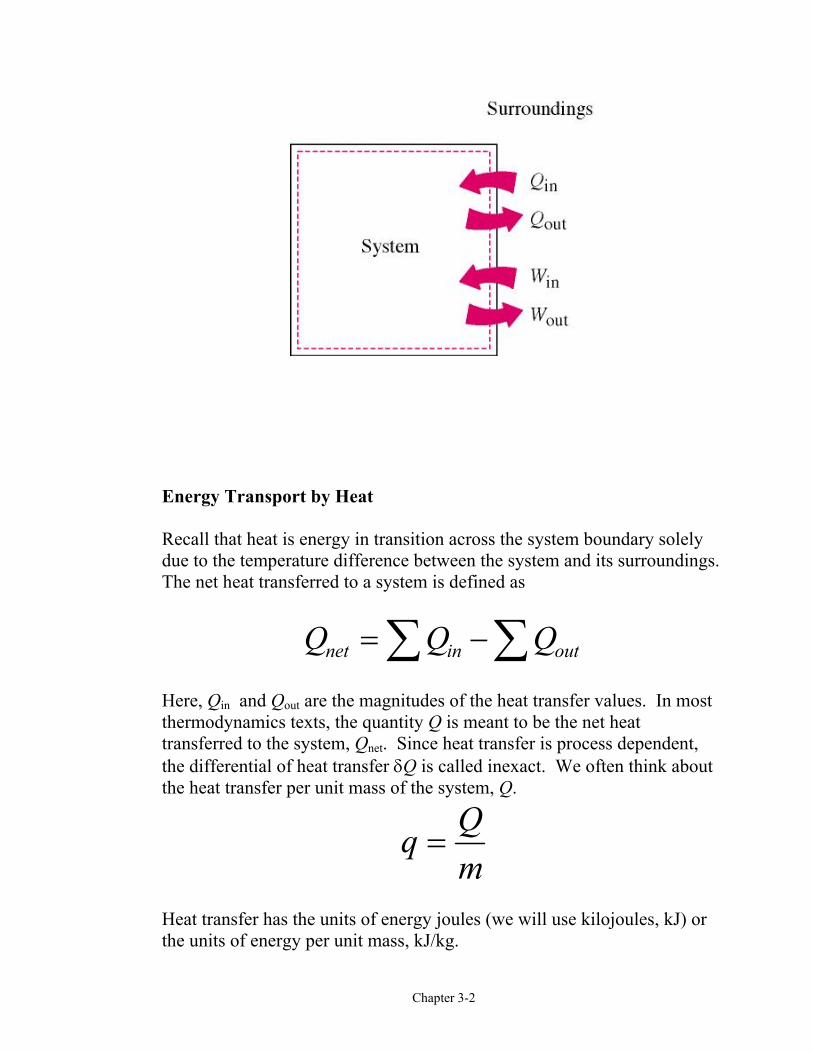
A sign convention is required for heat and work energy transfers, and theclassical sign convention is selected for these notes. According to theclassical sign convention, heat transfer to a system and work done by asystem are positive; heat transfer from a system and work done on a systemare negative. The system shown below has heat supplied to it and workdone by it.
In these study guide we will use the concept of net heat and net work.
Chapter 3-2
Energy Transport by Heat
Recall that heat is energy in transition across the system boundary solelydue to the temperature difference between the system and its surroundings.The net heat transferred to a system is defined as
Q Q Qnet in out= −∑∑Here, Qin and Qout are the magnitudes of the heat transfer values. In mostthermodynamics texts, the quantity Q is meant to be the net heattransferred to the system, Qnet. Since heat transfer is process dependent,the differential of heat transfer δQ is called inexact. We often think aboutthe heat transfer per unit mass of the system, Q.
q Qm
=
Heat transfer has the units of energy joules (we will use kilojoules, kJ) orthe units of energy per unit mass, kJ/kg.
Chapter 3-3
Since heat transfer is energy in transition across the system boundary dueto a temperature difference, there are three modes of heat transfer at theboundary that depend on the temperature difference between the boundarysurface and the surroundings. These are conduction, convection, andradiation. However, when solving problems in thermodynamics involvingheat transfer to a system, the heat transfer is usually given or is calculatedby applying the first law, or the conservation of energy, to the system.
An adiabatic process is one in which the system is perfectly insulated andthe heat transfer is zero.
For those of us who do not have the opportunity to have a complete coursein heat transfer theory and applications, the following is a shortintroduction to the basic mechanisms of heat transfer. Those of us whohave a complete course in heat transfer theory may elect to omit thismaterial at this time.
Heat transfer is energy in transition due to a temperature difference. Thethree modes of heat transfer are conduction, convection, and radiation.
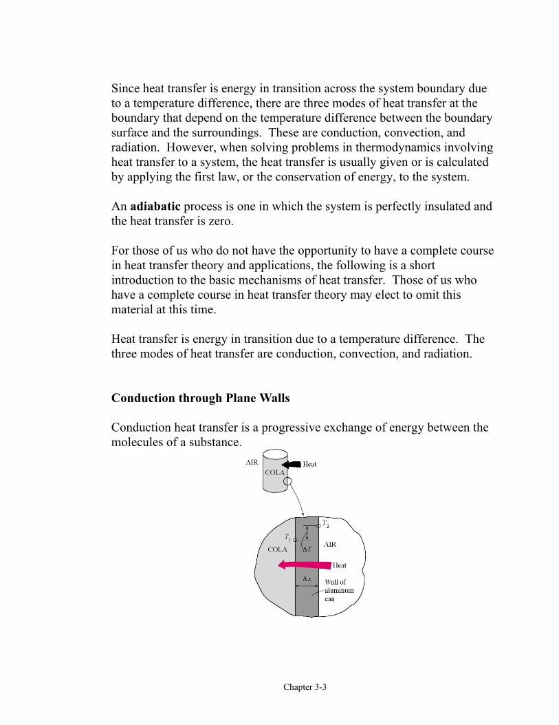
Conduction through Plane Walls
Conduction heat transfer is a progressive exchange of energy between themolecules of a substance.
Fourier's law of heat conduction is
Q A k dTdxcond t= −
hereQcond = heat flow per unit time (W)kt = thermal conductivity (W/m⋅K)A = area normal to heat flow (m2)dTdx
= temperature gradient in the direction of heat flow (°C/m)
Integrating Fourier's law
Q kA Txcond =
∆∆
Since T2>T1, the heat flows from right to left in the above figure.
Example 3-1
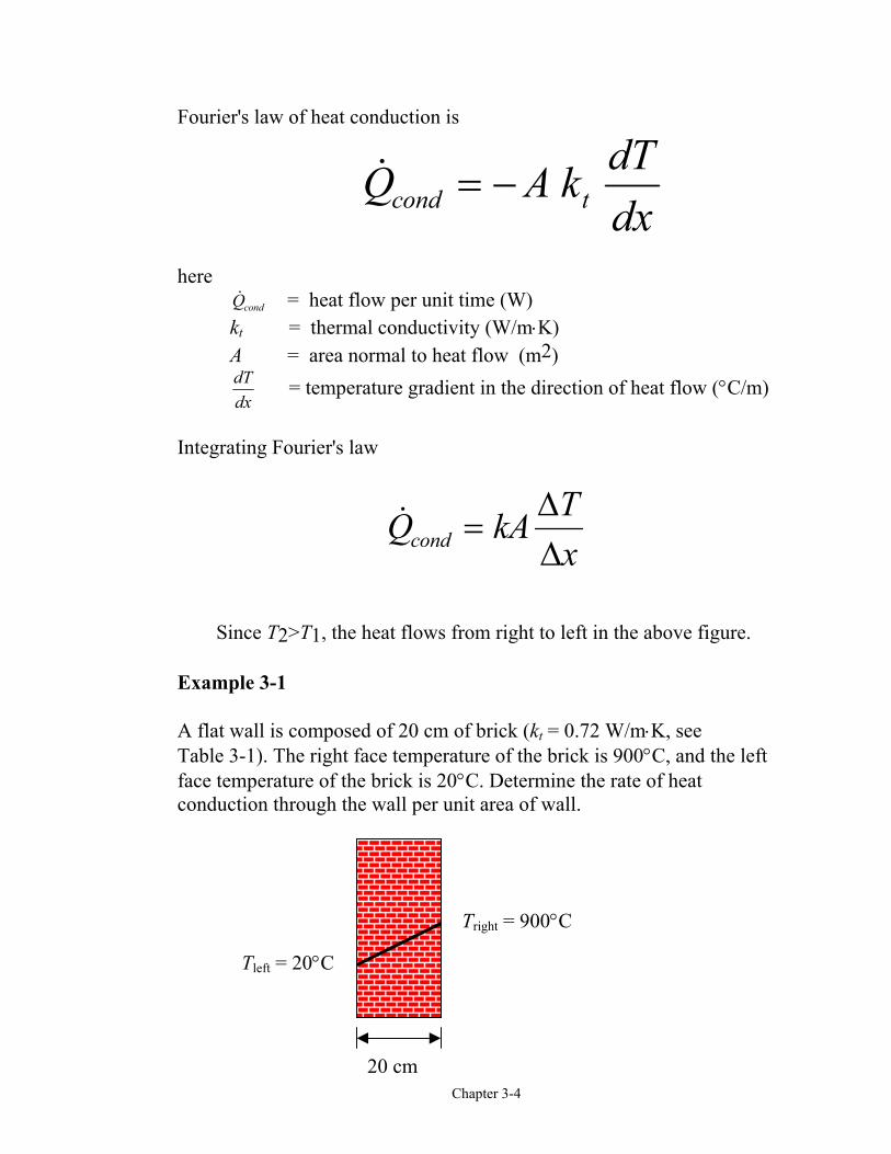
A flat wall is composed of 20 cm of brick (kt = 0.72 W/m⋅K, see Table 3-1). The right face temperature of the brick is 900°C, and the leftface temperature of the brick is 20°C. Determine the rate of heatconduction through the wall per unit area of wall.
Tright = 900°C
Tleft = 20°C
20 cm
Chapter 3-4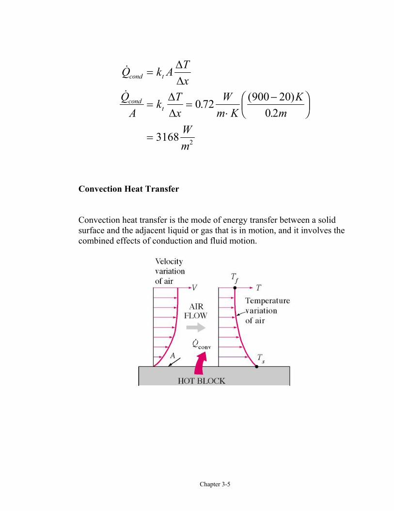
Chapter 3-5
. ( ).
Q k A Tx
QA
k Tx
Wm K
Km
Wm
cond t
condt
=
= =⋅
−FHG
IKJ
=
∆∆
∆∆
0 72 900 200 2
3168 2
Convection Heat Transfer
Convection heat transfer is the mode of energy transfer between a solidsurface and the adjacent liquid or gas that is in motion, and it involves thecombined effects of conduction and fluid motion.
Chapter 3-6
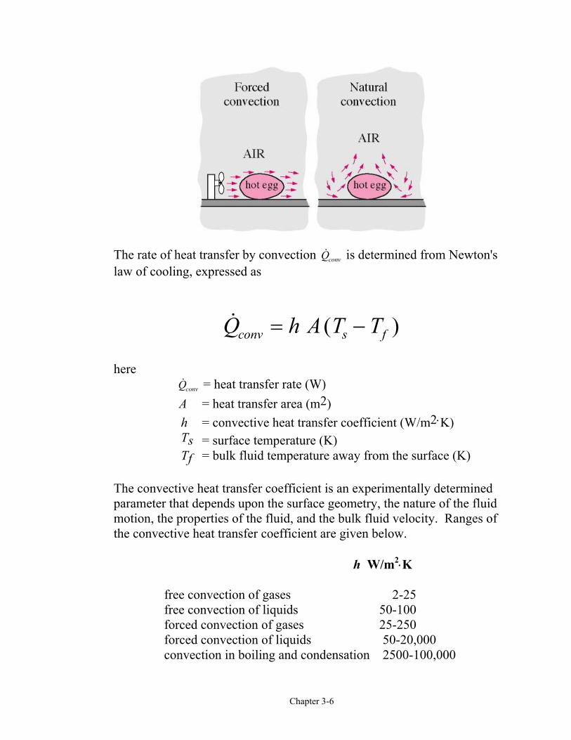
The rate of heat transfer by convection Qconv is determined from Newton'slaw of cooling, expressed as
( )Q h A T Tconv s f= −
here Qconv = heat transfer rate (W) A = heat transfer area (m2) h = convective heat transfer coefficient (W/m2⋅K)
Ts = surface temperature (K)Tf = bulk fluid temperature away from the surface (K)
The convective heat transfer coefficient is an experimentally determinedparameter that depends upon the surface geometry, the nature of the fluidmotion, the properties of the fluid, and the bulk fluid velocity. Ranges ofthe convective heat transfer coefficient are given below.
h W/m2⋅K
free convection of gases 2-25free convection of liquids 50-100forced convection of gases 25-250forced convection of liquids 50-20,000convection in boiling and condensation 2500-100,000

Chapter 3-7
Radiative Heat Transfer
Radiative heat transfer is energy in transition from the surface of one bodyto the surface of another due to electromagnetic radiation. The radiativeenergy transferred is proportional to the difference in the fourth power ofthe absolute temperatures of the bodies exchanging energy.
The net exchange of radiative heat transfer between a body surface and itssurroundings is given by
Q A T Trad s surr= −ε σ 4 4c hhere
Qrad = heat transfer per unit time (W)A = surface area for heat transfer (m2) σ = Stefan-Boltzmann constant, 5.67x10⁻⁸ W/m2K4
and 0.1713x10⁻⁸ BTU/h ft2 R4 ε = emissivity
Ts = absolute temperature of surface (K)Tsurr = absolute temperature of surroundings (K)

Chapter 3-8
Example 3-2
A vehicle is to be parked overnight in the open away from largesurrounding objects. It is desired to know if dew or frost may form on thevehicle top. Assume the following:
• Convection coefficient h from ambient air to vehicle top is 6.0W/m2⋅°C.
• Equivalent sky temperature is -18°C.• Emissivity of vehicle top is 0.84.• Negligible conduction from inside vehicle to top of vehicle.
Determine the temperature of the vehicle top when the air temperature is 5 oF. State which formation (dew or frost) occurs.
Ttop
Tsky = -Tair = 5 C
Qconv Qrad
Under steady-state conditions, the energy convected to the vehicle top isequal to the energy radiated to the sky.
Q Qconv rad=
The energy convected from the ambient air to the vehicle top is
( )Q A h T Tconv top air top= −
The energy radiated from the top to the night sky is
Chapter 3-9
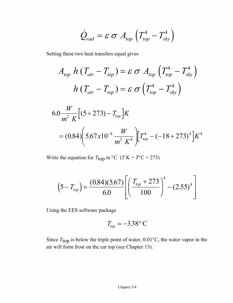
Q A T Trad top top sky= −ε σ 4 4d iSetting these two heat transfers equal gives
A h T T A T T
h T T T T
top air top top top sky
air top top sky
( )
( )
− = −
− = −
ε σ
ε σ
4 4
4 4
d id i
6 0 273
0 84 5 67 10 18 273
2
82 4
4 4 4
. (5 )
( . ) . ( )
Wm K
T K
x Wm K
T K
top
top
+ −
=FHG
IKJ − − +−
Write the equation for Ttop in °C (T K = T°C + 273)
5 084 676 0
273100
2 554
4− =+F
HGIKJ −
LNMM
OQPPT
Ttop
topd i ( . )(5. ).
( . )
Using the EES software package
Ttop = − °338. C
Since Ttop is below the triple point of water, 0.01°C, the water vapor in theair will form frost on the car top (see Chapter 13).
Chapter 3-10
Extra Problem
Explore what happens to Ttop as you vary the convective heat transfercoefficient. On a night when the atmosphere is particularly still and coldand has a clear sky, why do fruit growers use fans to increase the airvelocity in their fruit groves?
Energy Transfer by Work
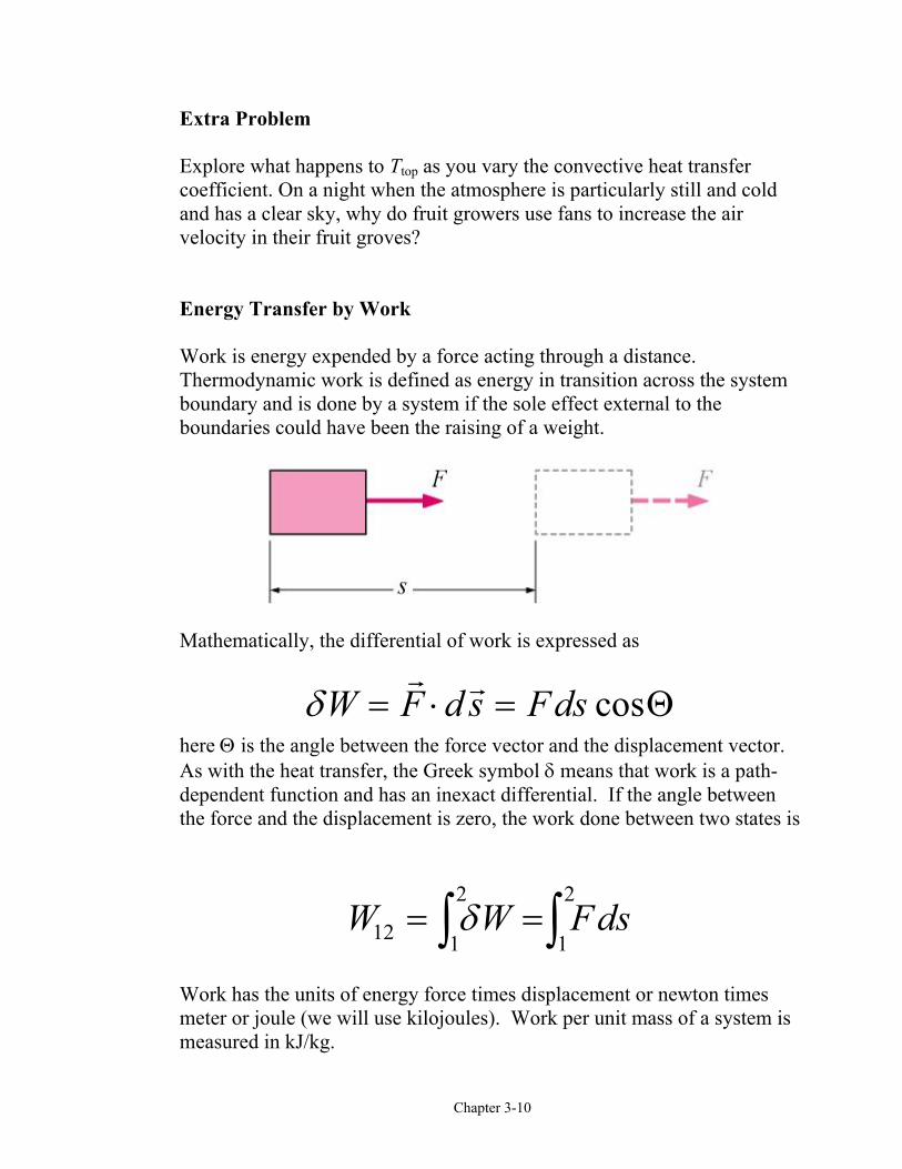
Work is energy expended by a force acting through a distance.Thermodynamic work is defined as energy in transition across the systemboundary and is done by a system if the sole effect external to theboundaries could have been the raising of a weight.
Mathematically, the differential of work is expressed as
δW F d s Fds= ⋅ = cosΘhere Θ is the angle between the force vector and the displacement vector.As with the heat transfer, the Greek symbol δ means that work is a path-dependent function and has an inexact differential. If the angle betweenthe force and the displacement is zero, the work done between two states is
W W Fds12 1
2
1
2= =z zδ
Work has the units of energy force times displacement or newton timesmeter or joule (we will use kilojoules). Work per unit mass of a system ismeasured in kJ/kg.
Chapter 3-11
Common Types of Work Energy
The net work done by the system may be in two forms. First, there can bework crossing the system boundary in the form of a rotating shaft orelectrical work. We will call shaft work and electrical work “other” work,that is, work not associated with a moving boundary. In thermodynamicselectrical energy is normally considered to be work energy rather than heatenergy, but the placement of the system boundary dictates whether toinclude electrical energy as work or heat. Second, the system may do workon its surroundings because of moving boundaries.
The net work done by a closed system is defined by
W W W Wnet out in other b= − +∑ ∑d iHere, Wout and Win are the magnitudes of the other work forms crossing theboundary. Wb is the work due to the moving boundary and will be positiveor negative depending upon the process.
Or
W W Wnet net other b= +e jSeveral types of “other” work (shaft work, electrical work, etc.) arediscussed in the text.
In the next section we will look at boundary work in detail. Review thetext material on other types of work such as shaft work, spring work,electrical work.
Boundary Work
Chapter 3-12
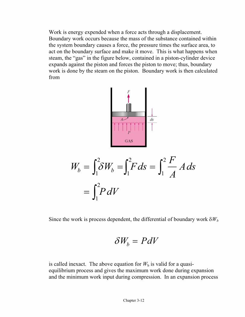
Work is energy expended when a force acts through a displacement.Boundary work occurs because the mass of the substance contained withinthe system boundary causes a force, the pressure times the surface area, toact on the boundary surface and make it move. This is what happens whensteam, the “gas” in the figure below, contained in a piston-cylinder deviceexpands against the piston and forces the piston to move; thus, boundarywork is done by the steam on the piston. Boundary work is then calculatedfrom
W W Fds FA
Ads
P dV
b b= = =
=
z z zzδ
1
2
1
2
1
2
1
2
Since the work is process dependent, the differential of boundary work δWb
δW PdVb =
is called inexact. The above equation for Wb is valid for a quasi-equilibrium process and gives the maximum work done during expansionand the minimum work input during compression. In an expansion process
Chapter 3-13
the boundary work must overcome friction, push the atmospheric air out ofthe way, and rotate a crankshaft.
b friction atm crank2
friction atm crank1( )
W W W W
F P A F ds
= + +
= + +∫To calculate the boundary work, the process by which the system changedstates must be known. Once the process is determined, the pressure-volume relationship for the process can be obtained and the integral in theboundary work equation can be performed. For each process we need todetermine
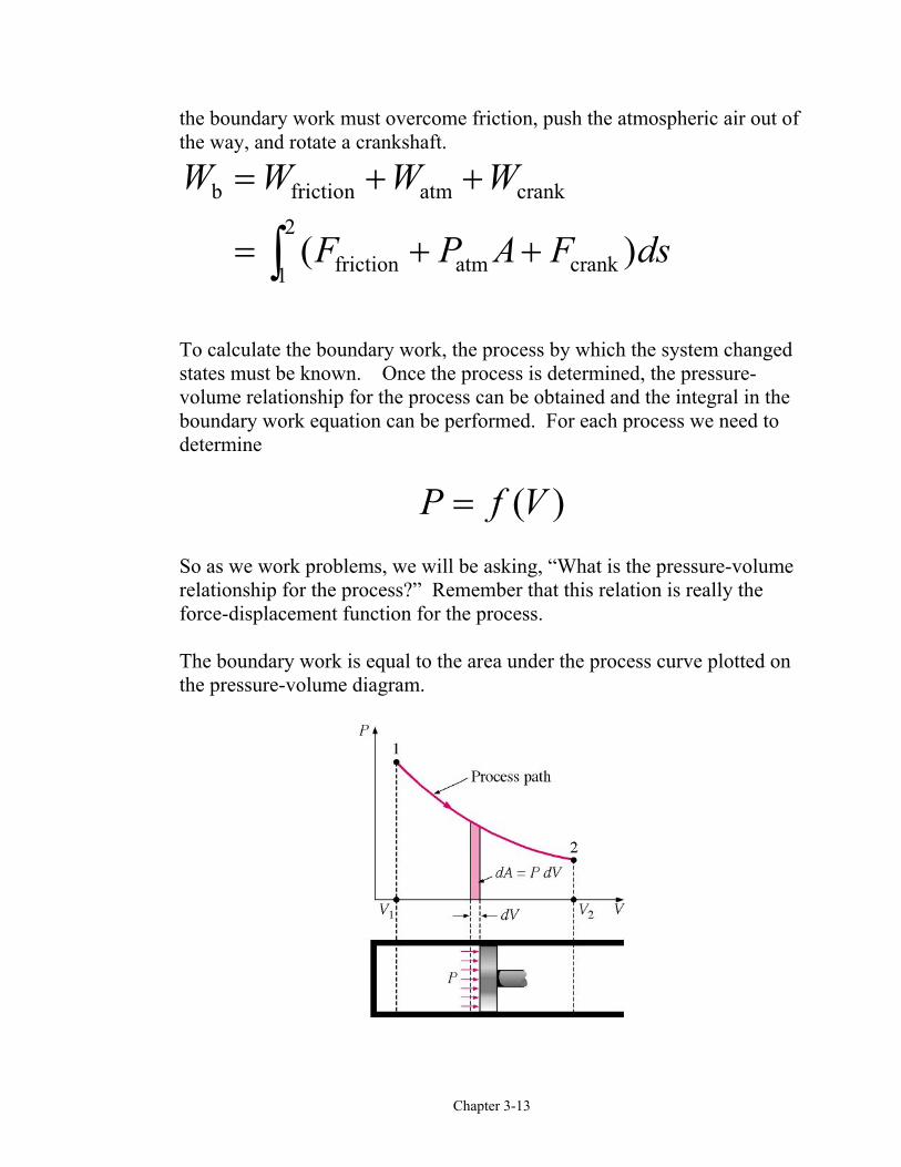
P f V= ( )So as we work problems, we will be asking, “What is the pressure-volumerelationship for the process?” Remember that this relation is really theforce-displacement function for the process.
The boundary work is equal to the area under the process curve plotted onthe pressure-volume diagram.
Chapter 3-14
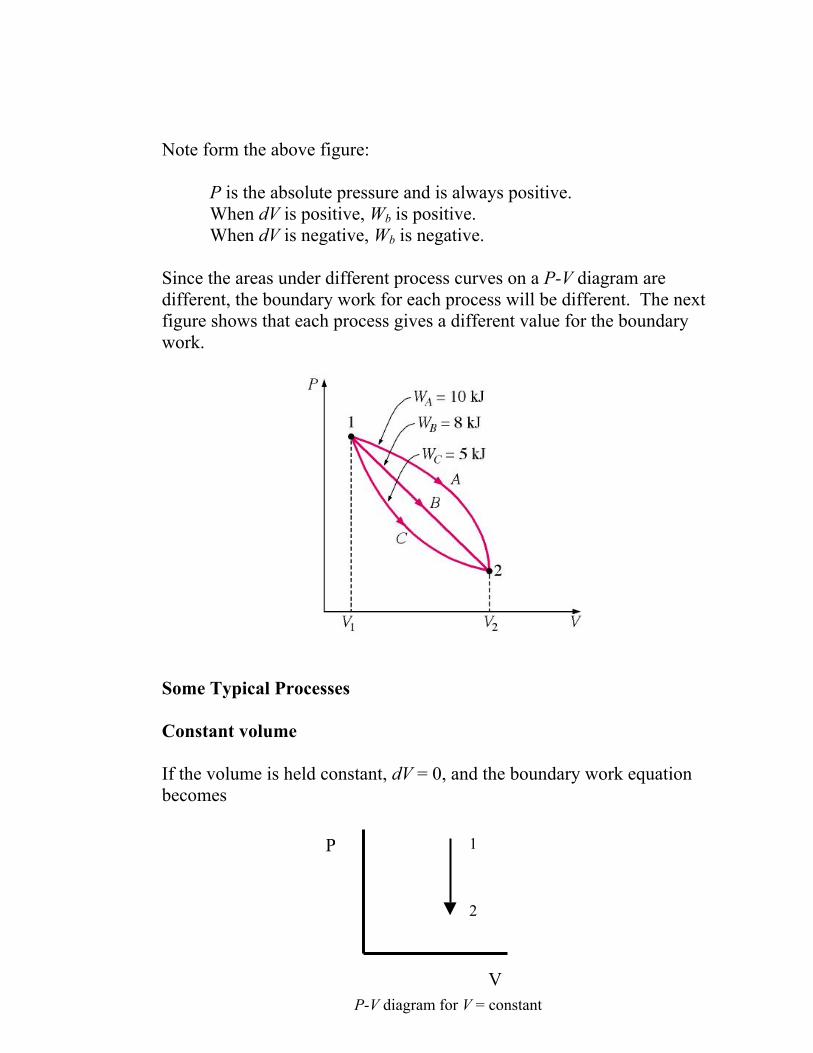
Note form the above figure:
P is the absolute pressure and is always positive.When dV is positive, Wb is positive.When dV is negative, Wb is negative.
Since the areas under different process curves on a P-V diagram aredifferent, the boundary work for each process will be different. The nextfigure shows that each process gives a different value for the boundarywork.
Some Typical Processes
Constant volume
If the volume is held constant, dV = 0, and the boundary work equationbecomes
P
V
1
2
P-V diagram for V = constant

Chapter 3-15
W PdVb = =z12 0If the working fluid is an ideal gas, what will happen to the temperature ofthe gas during this constant volume process?
Constant pressure
If the pressure is held constant, the boundary work equation becomes
W PdV P dV P V Vb = = = −z z1
2
1
2
2 1b gFor the constant pressure process shown above, is the boundary workpositive or negative and why?
Constant temperature, ideal gas
If the temperature of an ideal gas system is held constant, then the equationof state provides the pressure-volume relation
P mRTV
=
P
V
2 1
P-V diagram for P = constant
Chapter 3-16
Then, the boundary work is
W PdV mRTV
dV
mRT VV
b = =
=FHGIKJ
z z1
2
1
2
2
1
ln
Note: The above equation is the result of applying the ideal gas assumptionfor the equation of state. For real gases undergoing an isothermal (constanttemperature) process, the integral in the boundary work equation would bedone numerically.
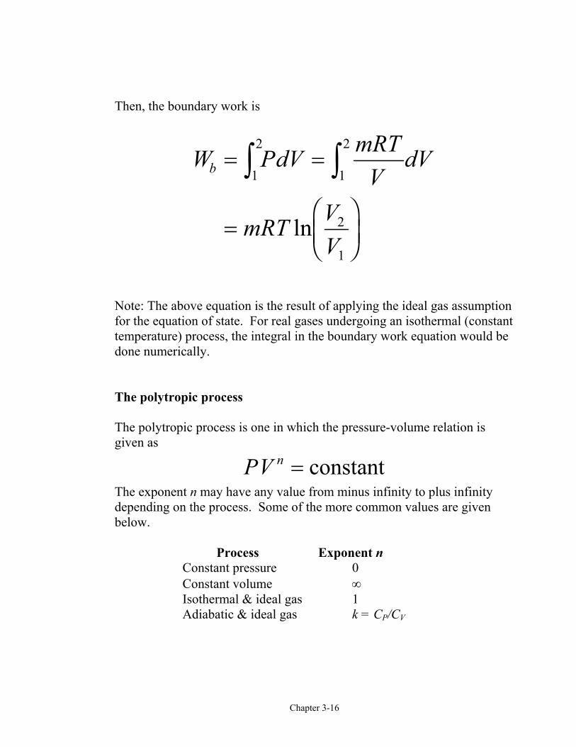
The polytropic process
The polytropic process is one in which the pressure-volume relation isgiven as
PV n = constantThe exponent n may have any value from minus infinity to plus infinitydepending on the process. Some of the more common values are givenbelow.
Process Exponent nConstant pressure 0Constant volume ∞Isothermal & ideal gas 1 Adiabatic & ideal gas k = CP/CV
Chapter 3-17
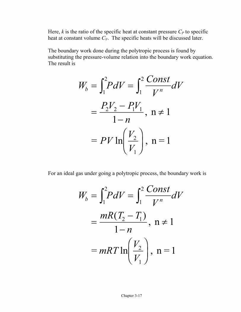
Here, k is the ratio of the specific heat at constant pressure CP to specificheat at constant volume CV. The specific heats will be discussed later.
The boundary work done during the polytropic process is found bysubstituting the pressure-volume relation into the boundary work equation.The result is
W PdV ConstV
dV
PV PVn
PV VV
b n= =
=−−
≠
FHGIKJ
z z1
2
1
2
2 2 1 1
2
1
1,
ln ,
n 1
= n = 1
For an ideal gas under going a polytropic process, the boundary work is
W PdV ConstV
dV
mR T Tn
mRT VV
b n= =
=−
−≠
FHGIKJ
z z1
2
1
2
2 1
2
1
1( ) ,
ln ,
n 1
= n = 1

Chapter 3-18
Notice that the results we obtained for an ideal gas undergoing a polytropicprocess when n = 1 are identical to those for an ideal gas undergoing theisothermal process.
Example 3-3
Three kilograms of nitrogen gas at 27°C and 0.15 MPa are compressedisothermally to 0.3 MPa in a piston-cylinder device. Determine theminimum work of compression, in kJ.
System: Nitrogen contained in a piston-cylinder device.
Process: Constant temperature
Property Relation: Check the reduced temperature and pressure fornitrogen. The critical state properties are found in Table A-1.
T TT
KK
T
P PP
MPaMPa
P P
Rcr
R
Rcr
R R
11
2
11
2 1
27 273126 2
2 38
0153 39
0 044
2 0 088
= =+
= =
= = =
= =
( ).
.
..
.
.
Since PR<<1 and T>2Tcr, nitrogen is an ideal gas, and we use the ideal gasequation of state as the property relation.
P-V diagram for T = constant
P
V
2
1WbNitrogen
gas
SystemBoundary
Chapter 3-19
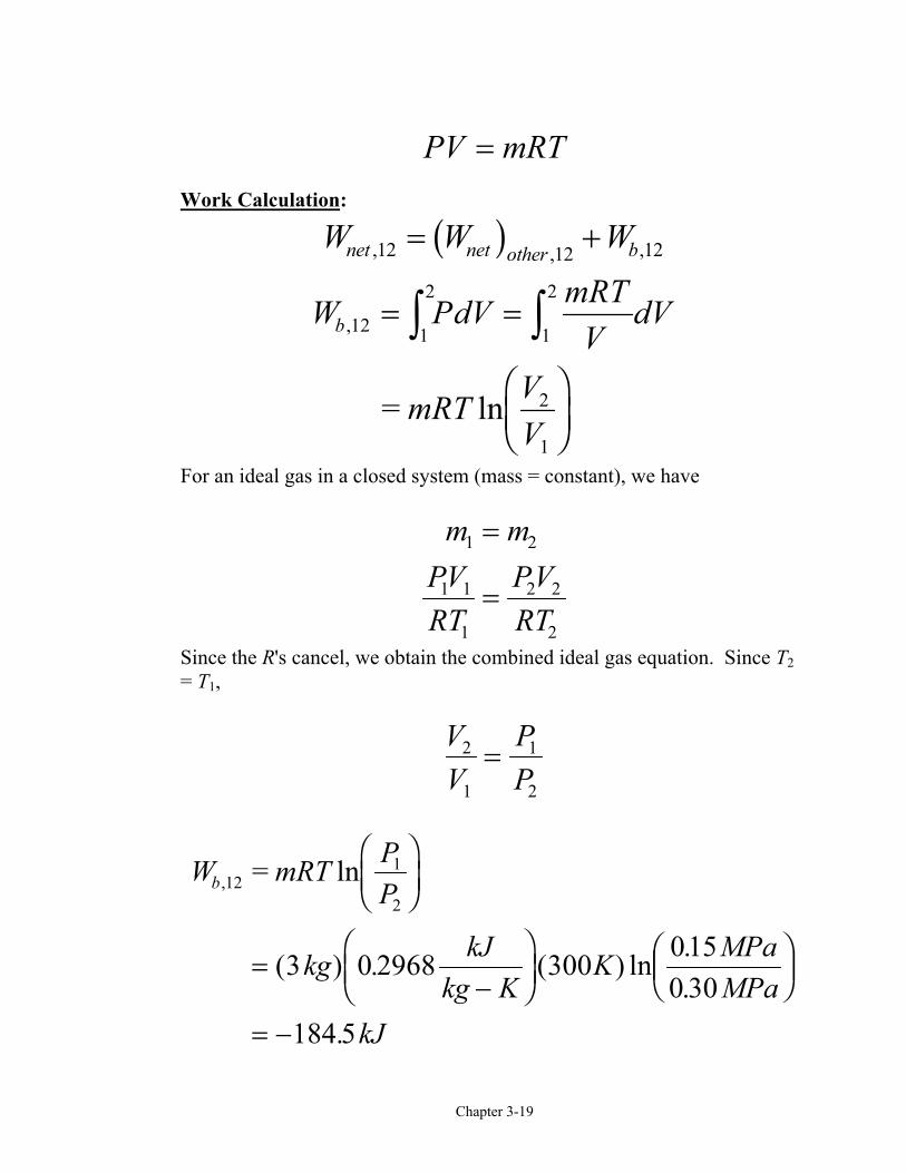
PV mRT=Work Calculation:
W W Wnet net other b, , ,12 12 12= +b gW PdV mRT
VdV
mRT VV
b ,
ln
12 1
2
1
2
2
1
= =
FHGIKJ
z z=
For an ideal gas in a closed system (mass = constant), we have
m mPVRT
PVRT
1 2
1 1
1
2 2
2
=
=
Since the R's cancel, we obtain the combined ideal gas equation. Since T2= T1,
VV
PP
2
1
1
2
=
W mRT PP
kg kJkg K
K MPaMPa
kJ
b , ln
( ) . ( ) ln ..
.
121
2
3 0 2968 300 0150 30
184 5
=FHGIKJ
=−
FHG
IKJ
FHG
IKJ
= −
Chapter 3-20
The net work is
W W kJnet b, , .12 120 184 5= + = −On a per unit mass basis
wW
mkJkgnet
net,
, .1212 615= = −
The net work is negative because work is done on the system during thecompression process. Thus, the work done on the system is 184.5 kJ, or184.5 kJ of work energy is required to compress the nitrogen.
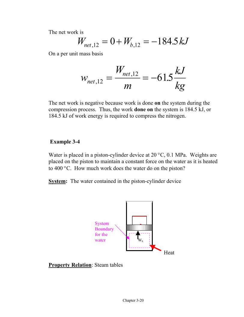
Example 3-4
Water is placed in a piston-cylinder device at 20 °C, 0.1 MPa. Weights areplaced on the piston to maintain a constant force on the water as it is heatedto 400 °C. How much work does the water do on the piston?
System: The water contained in the piston-cylinder device
Property Relation: Steam tables
Heat
SystemBoundaryfor thewater Wb
Chapter 3-21
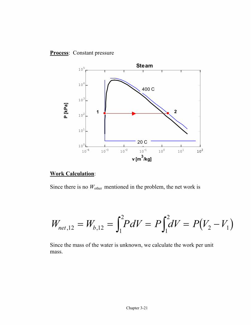
Process: Constant pressure
10-4 10-3 10-2 10-1 100 101 102102100
101
102
103
104
105
v [m3/kg]
P [k
Pa]
400 C
20 C
Steam
1 2
Work Calculation:
Since there is no Wother mentioned in the problem, the net work is
W W PdV P dV P V Vnet b, ,12 12 1
2
1
2
2 1= = = = −z z b gSince the mass of the water is unknown, we calculate the work per unitmass.
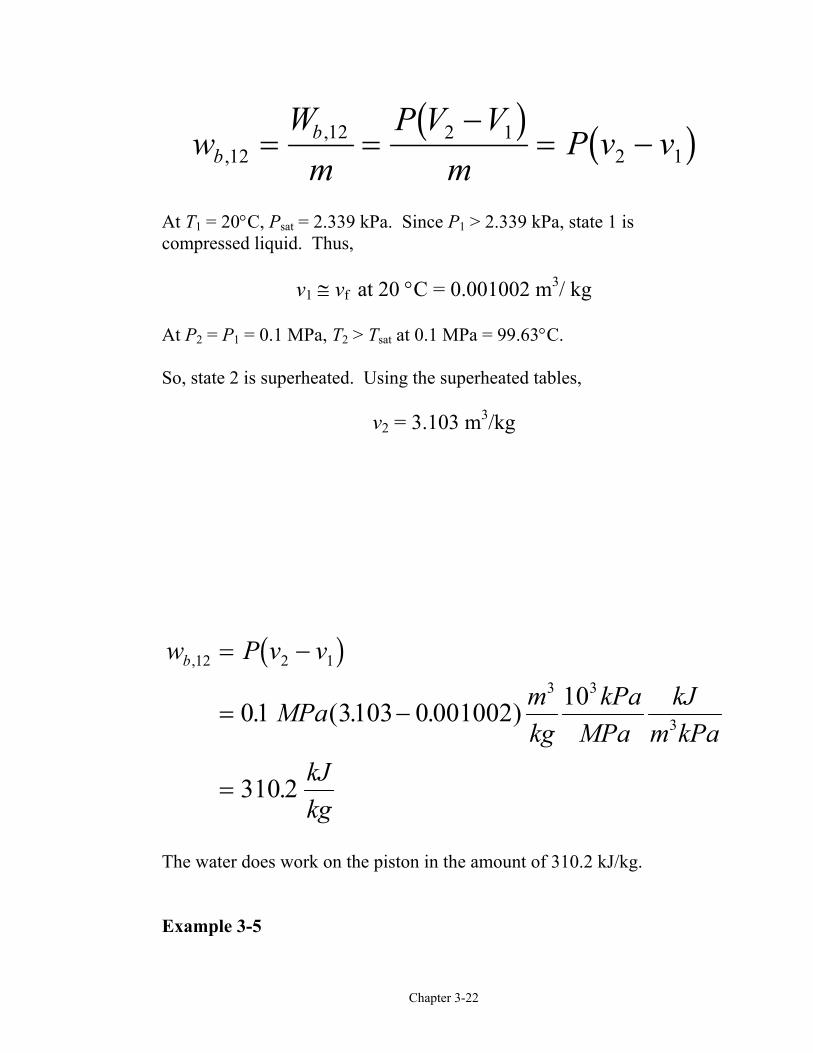
Chapter 3-22
wW
mP V V
mP v vb
b,
,12
12 2 12 1= =
−= −
b g b gAt T1 = 20°C, Psat = 2.339 kPa. Since P1 > 2.339 kPa, state 1 iscompressed liquid. Thus,
v1 ≅ vf at 20 °C = 0.001002 m3/ kg
At P2 = P1 = 0.1 MPa, T2 > Tsat at 0.1 MPa = 99.63°C.
So, state 2 is superheated. Using the superheated tables,
v2 = 3.103 m3/kg
w P v v
MPa mkg
kPaMPa
kJm kPa
kJkg
b,
. ( . . )
.
12 2 1
3 3
301 3103 0 001002 10
310 2
= −
= −
=
b g
The water does work on the piston in the amount of 310.2 kJ/kg.
Example 3-5
Chapter 3-23
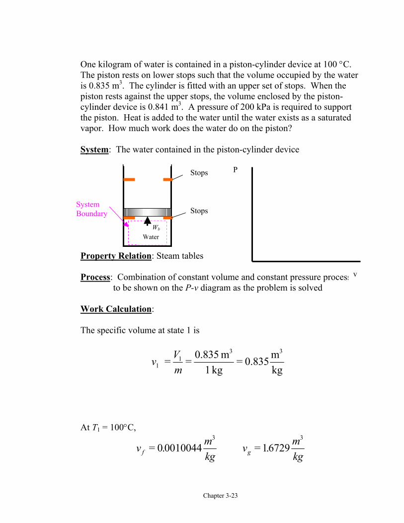
One kilogram of water is contained in a piston-cylinder device at 100 °C.The piston rests on lower stops such that the volume occupied by the wateris 0.835 m3. The cylinder is fitted with an upper set of stops. When thepiston rests against the upper stops, the volume enclosed by the piston-cylinder device is 0.841 m3. A pressure of 200 kPa is required to supportthe piston. Heat is added to the water until the water exists as a saturatedvapor. How much work does the water do on the piston?
System: The water contained in the piston-cylinder device
Property Relation: Steam tables
Process: Combination of constant volume and constant pressure processesto be shown on the P-v diagram as the problem is solved
Work Calculation:
The specific volume at state 1 is
v Vm1
1 = = 0.835 m1 kg
= 0.835 mkg
3 3
At T1 = 100°C,
v mkg
v mkgf g= . = .0 0010044 16729
3 3
P
v
WaterWb
SystemBoundary
Stops
Stops
Chapter 3-24
Therefore, vf < v1 < vg and state 1 is in the saturation region; so P1 = 101.35 kPa.
Now let’s consider the processes for the water.
Process 1-2: The volume stays constant until the pressure increasesto 200 kPa. Then the piston will move.
v v mkg2 1
3
0 835= = .
Process 2-3: Piston lifts off the bottom stops while the pressure staysconstant. Does the piston hit the upper stops before orafter reaching the saturated vapor state?
Let's set
v Vm
mkg
mkg3
33 30841
10841 = = . = .
At P3 = P2 = 200 kPa
v mkg
v mkgf g= . = .0 0010061 08857
3 3
Thus, vf < v3 < vg. So, the piston hits the upper stops before the waterreaches the saturated vapor state. Now we have to consider a third process.
Process 3-4: With the piston against the upper stops, the volumeremains constant during the final heating to thesaturated vapor state and the pressure increases.
Because the volume is constant in process 3-to-4, v4 = v3 = 0.841 m3/kgand v4 is a saturated vapor state. Interpolating in either the saturationpressure table or saturation temperature table at v4 = vg gives

Chapter 3-25
StateP kPav v
T Cg
42113
1224
44
:.=
=UVW
= °
The net work for the heating process is (the “other” work is zero)
W W PdV PdV PdV PdV
mP v v
kg kPa mkg
kJm kPa
kJ
net b, ,
( )
( )( )( . . )
.
14 14 1
4
1
2
2
3
3
4
3 23
3
0 0
1 200 0 841 0 835
12
= = = + +
= + − +
= −
=
z z z z
Later in Chapter 4, we will apply the conservation of energy, or the firstlaw of thermodynamics, to this process to determine the amount of heattransfer required.
Example 3-6
Air undergoes a constant pressure cooling process in which the temperaturedecreases by 100°C. What is the magnitude and direction of the work forthis process?

T2= T1-100°C
System:
roperty Relation: Ideal gas law, Pv = RT
Process: Co stant pressure
Work Calcu
Wn
The work pe
,1netw
The work doEnergy Tra
The conservopen systemthe system bwork crossincrosses the sopen system
AirWb
SystemBoundary
T1
P-V diagram for T = constant
P
V
21
n
lation: Neglecting
W
mR Tet b,
(12
2
0= +
=
r unit mass is
,122
(0.287
netWm
kg
= =
=
ne on the air is 28nsport by Mass
ation of mass and s or control volumoundary or controlg the system bounystem boundaries. may change when
P
Chapter 3-26
the “other” w
PdV
T,
)12 1
2
1
=
−z
2 1( )
)( 10
R T T
kJK
−
−⋅
.7 kJ/kg.
the conservaties apply to sy surface. In adaries, mass c Thus, the ma mass enters o
ork
P V V( )2 1= −
0 ) 28.7 kJKkg
= −
on of energy principles forstems having mass crossingddition to the heat transfer andarries energy with it as itss and energy content of ther leaves the control volume.
Wnet
Chapter 3-27
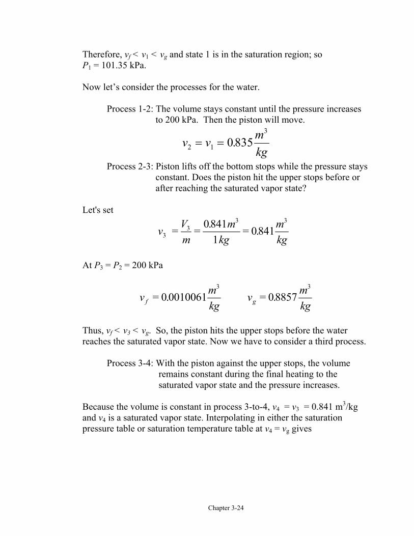
Typical control volume or open system
Thermodynamic processes involving control volumes can be considered intwo groups: steady-flow processes and unsteady-flow processes. During asteady-flow process, the fluid flows through the control volume steadily,experiencing no change with time at a fixed position.
Mass Flow Rate
Mass flow through a cross-sectional area per unit time is called the massflow rate m . It is expressed as
m V dAnA
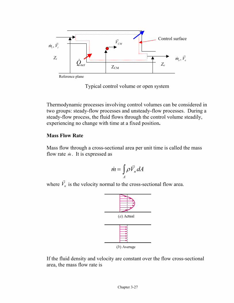
= z ρwhere Vn is the velocity normal to the cross-sectional flow area.
If the fluid density and velocity are constant over the flow cross-sectionalarea, the mass flow rate is
Reference plane
Qnet ZCM
VCM
Control surface
,m Ve e
,m Vi i
Ze
Zi
Chapter 3-28
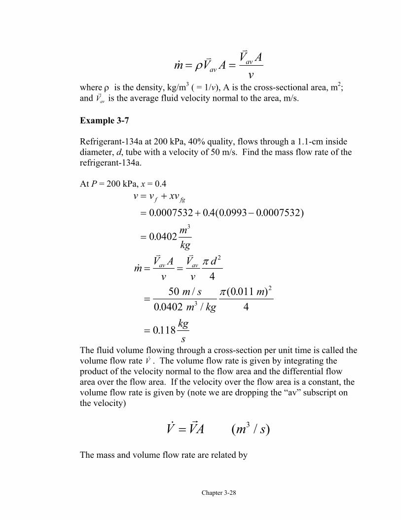
m V A V Avav
av= =ρ
where ρ is the density, kg/m3 ( = 1/v), A is the cross-sectional area, m2;and Vav is the average fluid velocity normal to the area, m/s.
Example 3-7
Refrigerant-134a at 200 kPa, 40% quality, flows through a 1.1-cm insidediameter, d, tube with a velocity of 50 m/s. Find the mass flow rate of therefrigerant-134a.
At P = 200 kPa, x = 0.4v v xv
mkg
f fg= +
= + −
=
0 0007532 0 4 0 0993 0 0007532
0 04023
. . ( . . )
.
/. /
( . )
.
m V Av
Vv
d
m sm kg
m
kgs
av av= =
=
=
π
π
2
3
24
500 0402
0 0114
0118
The fluid volume flowing through a cross-section per unit time is called thevolume flow rate V . The volume flow rate is given by integrating theproduct of the velocity normal to the flow area and the differential flowarea over the flow area. If the velocity over the flow area is a constant, thevolume flow rate is given by (note we are dropping the “av” subscript onthe velocity)
( / )V VA m s= 3
The mass and volume flow rate are related by
Chapter 3-29
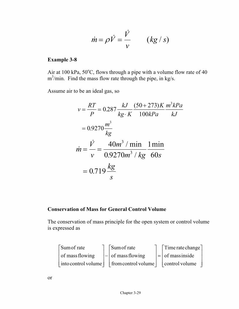
( / )m V Vv
kg s= =ρ
Example 3-8
Air at 100 kPa, 50oC, flows through a pipe with a volume flow rate of 40m3/min. Find the mass flow rate through the pipe, in kg/s.
Assume air to be an ideal gas, so
v RTP
kJkg K
KkPa
m kPakJ
mkg
= =⋅
+
=
0 287 273100
0 9270
3
3
. (50 )
.
/ min. /
min
.
m Vv
mm kg s
kgs
= =
=
400 9270
160
0 719
3
3
Conservation of Mass for General Control Volume
The conservation of mass principle for the open system or control volumeis expressed as
Sumof rateof massflowinginto control volume
Sumof rateof massflowingfromcontrol volume
Time ratechangeof massinsidecontrol volume
L
NMMM
O
QPPP−L
NMMM
O
QPPP=L
NMMM
O
QPPP
or

Chapter 3-30
( / )m m m kg sin out system∑ ∑− = ∆
Steady-State, Steady-Flow Processes
Most energy conversion devices operate steadily over long periods of time.The rates of heat transfer and work crossing the control surface areconstant with time. The states of the mass streams crossing the controlsurface or boundary are constant with time. Under these conditions themass and energy content of the control volume are constant with time.
0CVCV
dm mdt
= ∆ =
Steady-state, Steady-Flow Conservation of Mass:
Since the mass of the control volume is constant with time during thesteady-state, steady-flow process, the conservation of mass principlebecomes
Sumof rateof massflowinginto control volume
Sumof rateof massflowingfromcontrol volume
L
NMMM
O
QPPP=L
NMMM
O
QPPP
or
( / )m m kg sin out∑ ∑=
Special Case: Steady Flow of an Incompressible Fluid
The mass flow rate is related to volume flow rate and fluid density by
Chapter 3-31
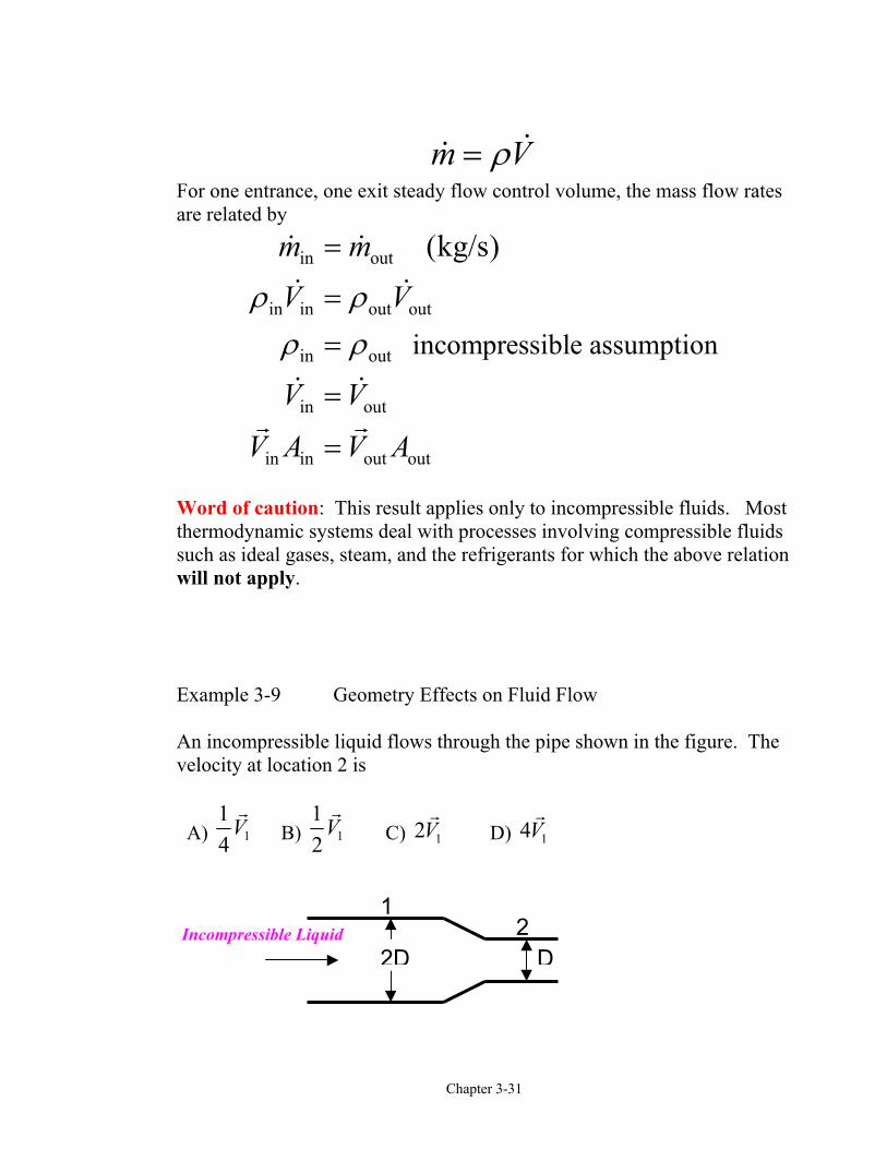
m Vρ=For one entrance, one exit steady flow control volume, the mass flow ratesare related by
in out
in in out out
in out
in out
in in out out
incompressible assumption
(kg/s)
m m
V V
V V
V A V A
ρ ρρ ρ
=
==
=
=
Word of caution: This result applies only to incompressible fluids. Mostthermodynamic systems deal with processes involving compressible fluidssuch as ideal gases, steam, and the refrigerants for which the above relationwill not apply.
Example 3-9 Geometry Effects on Fluid Flow
An incompressible liquid flows through the pipe shown in the figure. Thevelocity at location 2 is
A) 114
V B) 112
V C) 12V D) 14V
21
Incompressible LiquidD2D
Chapter 3-32
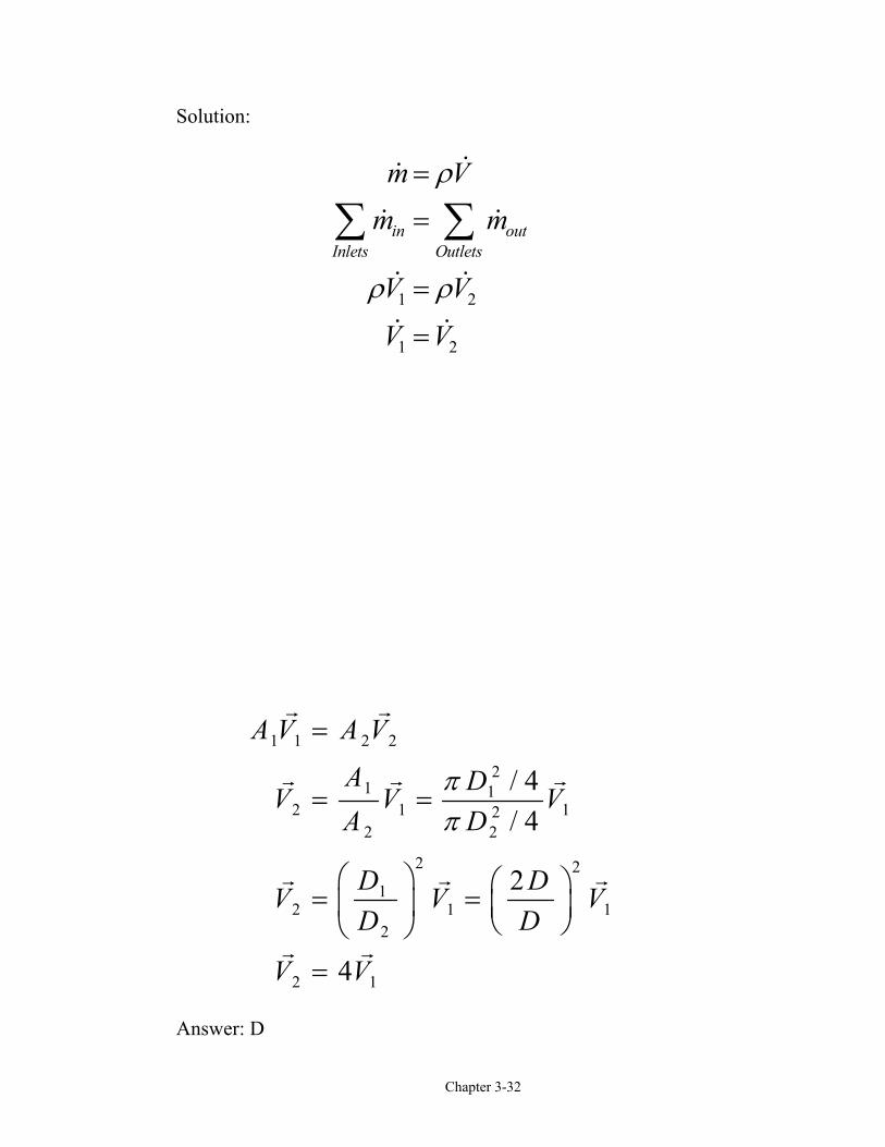
Solution:
Answer: D
1 1 2 2
21 1
2 1 122 2
2 21
2 1 12
2 1
/ 4/ 4
2
4
A V A V
A DV V VA D
D DV V VD D
V V
ππ
=
= =
= =
=
1 2
1 2
in outInlets Outlets
m Vm m
V V
V V
ρ
ρ ρ
=
=
=
=
∑ ∑
Chapter 3-33
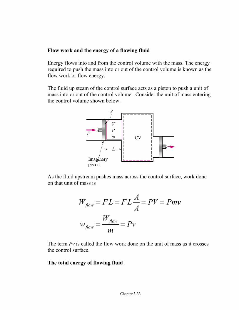
Flow work and the energy of a flowing fluid
Energy flows into and from the control volume with the mass. The energyrequired to push the mass into or out of the control volume is known as theflow work or flow energy.
The fluid up steam of the control surface acts as a piston to push a unit ofmass into or out of the control volume. Consider the unit of mass enteringthe control volume shown below.
As the fluid upstream pushes mass across the control surface, work doneon that unit of mass is
flow
flowflow
AW F L F L PV PmvA
Ww Pv
m
= = = =
= =
The term Pv is called the flow work done on the unit of mass as it crossesthe control surface.
The total energy of flowing fluid

Chapter 3-34
The total energy carried by a unit of mass as it crosses the control surfaceis the sum of the internal energy, flow work, potential energy, and kineticenergy.
θ = + + +
= + +
u Pv V gz
h V gz
2
2
2
2
Here we have used the definition of enthalpy, h = u + Pv.
Energy transport by mass
Amount of energy transport:2
(kJ)2mass
VE m m h gzθ
= = + +
Rate of energy transport:2
( )2mass
VE m m h gz kWθ
= = + +
Related Documents