Central Eyre Iron Project Mining Lease Proposal CHAPTER 3 DESCRIPTION OF THE PROPOSED MINING OPERATIONS CHAPTER 3: DESCRIPTION OF THE PROPOSED MINING OPERATIONS

Welcome message from author
This document is posted to help you gain knowledge. Please leave a comment to let me know what you think about it! Share it to your friends and learn new things together.
Transcript

Central Eyre Iron Project Mining Lease Proposal
CHAPTER 3 DESCRIPTION OF THE PROPOSED MINING
OPERATIONS
CHAPTER 3: DESCRIPTION OF THE PROPOSED
MINING OPERATIONS

COPYRIGHT Copyright © IRD Mining Operations Pty Ltd and Iron Road Limited, 2015 All rights reserved
This document and any related documentation is protected by copyright owned by IRD Mining Operations Pty Ltd and Iron Road Limited. The content of this document and any related documentation may only be copied and distributed for purposes of section 35A of the Mining Act, 1971 (SA) and otherwise with the prior written consent of IRD Mining Operations Pty Ltd and Iron Road Limited.
DISCLAIMER A declaration has been made on behalf of IRD Mining Operations Pty Ltd by its Managing Director that he has taken reasonable steps to review the information contained in this document and to ensure its accuracy as at 5 November 2015.
Subject to that declaration:
(a) in writing this document, Iron Road Limited has relied on information provided by specialist consultants, government agencies, and other third parties. Iron Road Limited has reviewed all information to the best of its ability but does not take responsibility for the accuracy or completeness; and
(b) this document has been prepared for information purposes only and, to the full extent permitted by law, Iron Road Limited, in respect of all persons other than the relevant government departments, makes no representation and gives no warranty or undertaking, express or implied, in respect to the information contained herein, and does not accept responsibility and is not liable for any loss or liability whatsoever arising as a result of any person acting or refraining from acting on any information contained within it.

Chapter 3: Description of the Proposed Mining Operations Mineral Claim 4383 5 Nov 2015 Page i
3 Description of the Proposed Mining Operations ..... 3-1
3.1 Overview of Mining Operation ................................................................................................ 3-1 3.1.1 Phases of Mining ...................................................................................................... 3-1 3.1.2 Mining Operation ..................................................................................................... 3-2
3.2 Reserves, Products and Market ............................................................................................... 3-5 3.2.1 Geological Environment ........................................................................................... 3-5 3.2.2 Reserves and Resources ........................................................................................... 3-9 3.2.3 Product and Market ............................................................................................... 3-11
3.3 Exploration Activities ............................................................................................................. 3-12
3.4 Mining Description ................................................................................................................. 3-16 3.4.1 Mining Method ....................................................................................................... 3-16 3.4.2 Mining Schedule ..................................................................................................... 3-18 3.4.3 Construction Phase Summary ................................................................................ 3-22 3.4.4 Use of Explosives .................................................................................................... 3-23 3.4.5 Type of Equipment ................................................................................................. 3-26 3.4.6 Stockpiles ................................................................................................................ 3-27 3.4.7 In-Pit Crushing and Conveying Plant Description ................................................... 3-30 3.4.8 Ore Processing Facility Description ........................................................................ 3-32 3.4.9 Concentrate Handling Facilities Description .......................................................... 3-36 3.4.10 Mine Dewatering .................................................................................................... 3-37 3.4.11 Process Water Requirements ................................................................................. 3-38
3.5 Waste ..................................................................................................................................... 3-42 3.5.1 Processing Wastes .................................................................................................. 3-42 3.5.2 Integrated Waste Landform ................................................................................... 3-42 3.5.3 Industrial and Commerical Wastes......................................................................... 3-53
3.6 Supporting Surface Infrastructure ......................................................................................... 3-55 3.6.1 Site Access .............................................................................................................. 3-55 3.6.2 Accommodation, Office and Maintenance Areas .................................................. 3-58 3.6.3 Emergency Services ................................................................................................ 3-60 3.6.4 Public Roads, Services and Utilities ........................................................................ 3-63 3.6.5 Visual Screening...................................................................................................... 3-65 3.6.6 Fuel and Chemical Storage ..................................................................................... 3-65 3.6.7 Site Security ............................................................................................................ 3-66 3.6.8 Stormwater Management ...................................................................................... 3-68
3.7 Mine Completion ................................................................................................................... 3-68 3.7.1 Surface Infrastructure and Buildings ...................................................................... 3-69 3.7.2 Mine Pit .................................................................................................................. 3-69 3.7.3 Integrated Waste Landform ................................................................................... 3-72 3.7.4 Land Use Options.................................................................................................... 3-73 3.7.5 Native Vegetation Cover ........................................................................................ 3-76

Page ii Mineral Claim 4383 5 Nov 2015 Chapter 3: Description of the Proposed Mining Operations
3.8 Resource Inputs ..................................................................................................................... 3-76 3.8.1 Workforce and Hours of Operation ........................................................................ 3-76 3.8.2 Energy Sources ....................................................................................................... 3-77 3.8.3 Water Sources ........................................................................................................ 3-78
List of Figures Figure 3-1 Mine Site Layout .................................................................................................................. 3-3 Figure 3-2 Surface Geology of the Exploration Licence ........................................................................ 3-7 Figure 3-3 Geological Age of CEIP Deposit ........................................................................................... 3-8 Figure 3-4 CEIP Orebody ....................................................................................................................... 3-9 Figure 3-5 Orebody Mineralisation Looking West ................................................................................ 3-9 Figure 3-6 Aeromagnetic Response of Exploration Licence ............................................................... 3-14 Figure 3-7 Stages of Iron Road’s Drilling Programmes ....................................................................... 3-15 Figure 3-8 Simplified Mining Process Diagram ................................................................................... 3-17 Figure 3-9 Indicative Progress of the Mine Pit at Year 5, 10, 15, 20, 25 and Post Closure ................ 3-20 Figure 3-10 Indicative Progress of the IWL at Year 5, 10, 15, 20, 25 and Post Closure ...................... 3-21 Figure 3-11 Indicative Construction Schedule .................................................................................... 3-22 Figure 3-12 Explosives Storage and Manufacturing Facility ............................................................... 3-25 Figure 3-13 Ore Processing Plant Layout ............................................................................................ 3-33 Figure 3-14 Simplified Process Flow Diagram for Ore Processing Facility .......................................... 3-34 Figure 3-15 Predicted Average Annual Dewatering Rates during the 25 years of Mine Operation .. 3-38 Figure 3-16 Locations of Water Storage Dams ................................................................................... 3-39 Figure 3-17 Proposed Dewatering Well Locations ............................................................................. 3-40 Figure 3-18 Simplified Process Water Flow Diagram ......................................................................... 3-41 Figure 3-19 Provisional Additional Waste Storage Locations ............................................................. 3-44 Figure 3-20 Conceptual IWL Cross-Section ......................................................................................... 3-48 Figure 3-21 Conceptual Design of the IWL (view from south-east to north-west) ............................ 3-49 Figure 3-22 Concept Landform Cover Profiles (from MWH 2015 in Appendix S) .............................. 3-50 Figure 3-23 Access Route to the Mine Site ......................................................................................... 3-57 Figure 3-24 Indicative Layout of Mine Site Camp (Source: DoricGroup) ............................................ 3-59 Figure 3-25 Mine Administration Areas, Emergency Services and Warehousing .............................. 3-61 Figure 3-26 Mine Maintenance Facilities ........................................................................................... 3-62 Figure 3-27 Existing Public Roads, Water Supply and Electricity Network ......................................... 3-64 Figure 3-28 Site Fencing and Site Security .......................................................................................... 3-67 Figure 3-29 Definition of Terms of Instability (Source: DIR 1997) ...................................................... 3-70 Figure 3-30 Required Stand-off Distances for Safety Bund Wall (Source: DIR 1997) ......................... 3-70 Figure 3-31 Indicative Safety Bund Wall Offsets from Edge of Mine Pit ............................................ 3-71 Figure 3-32 Predicted Pit Lake Level Post Closure .............................................................................. 3-72 Figure 3-33 Final Post Mining Land Use within Proposed Mining Lease ............................................ 3-74 Figure 3-34 Final Post Mining Cross Sections ..................................................................................... 3-75
List of Plates Plate 3-1 Coarse CEIP Magnetite Concentrate ................................................................................... 3-12 Plate 3-2 Illustration of Excavator Feeding a Fully Mobile Crusher and Track Mounted Conveyor (Source: MMD) ................................................................................................................................... 3-16 Plate 3-3 Indicative Fully Mobile Crusher Stations (Source: MMD) ................................................... 3-30 Plate 3-4 Example of an IWL Spreader ............................................................................................... 3-46 Plate 3-5 Example of Mobile Spreader Placing Material at the Toe of Slope ..................................... 3-53
Chapter 3: Description of the Proposed Mining Operations Mineral Claim 4383 5 Nov 2015 Page iii
List of Tables Table 3-1 Key Characteristics of the Proposed Mining Lease ............................................................... 3-4 Table 3-2 CEIP Global Mineral Resource Estimate (27 February 2015) .............................................. 3-10 Table 3-3 Iron Road Ore Reserve Summary (CEIP) (27 February 2015) ............................................. 3-10 Table 3-4 Resource History ................................................................................................................. 3-10 Table 3-5 Indicative Concentrate Specifications ................................................................................ 3-11 Table 3-6 Stages of Resource Drilling by Iron Road ............................................................................ 3-13 Table 3-7 Mining Schedule ................................................................................................................. 3-19 Table 3-8 Explosives Storage and Manufacturing Facility Capacities ................................................. 3-26 Table 3-9 Indicative Mobile Fleet ....................................................................................................... 3-27 Table 3-10 Topsoil Temporary Storage Area ...................................................................................... 3-28 Table 3-11 Subsoil Stockpile Summary ............................................................................................... 3-29 Table 3-12 Mobile Primary Crusher Specifications ............................................................................. 3-31 Table 3-13 Ore Processing Facility – Building Dimensions ................................................................. 3-35 Table 3-14 Preliminary Mine Waste Materials Inventory for the CEIP (MWH 2015 in Appendix S) .. 3-45 Table 3-15 Estimates of soil resource requirements for cover profile (from MWH 2015 in Appendix S) ......................................................................................................................................... 3-50 Table 3-16 Indicative Waste Streams at the Proposed Mine Site ...................................................... 3-54 Table 3-17 Typical Mine Pit Wall Slope Angles (Coffey 2014) ............................................................ 3-70 Table 3-18 Horizontal Distance from Toe to Crest of Pit Slope .......................................................... 3-71 Table 3-19 Required Stand-off Distances from Mine Pit Edge to Safety Bund Wall .......................... 3-71 Table 3-20 Projected Peak Workforce at the Proposed Mine ............................................................ 3-77 Table 3-21 Electricity Use and Calculated GHG Emissions ................................................................. 3-77 Table 3-22 Diesel Use and Calculated GHG Emissions ....................................................................... 3-77 Table 3-23 Expected Annual Water Usage for CEIP Mining Operations Post Start Up ...................... 3-79

Page iv Mineral Claim 4383 5 Nov 2015 Chapter 3: Description of the Proposed Mining Operations
This page has been left blank intentionally.

Chapter 3: Description of the Proposed Mining Operations Mineral Claim 4383 5 Nov 2015 Page 3-1
3 Description of the Proposed Mining Operations This chapter outlines the iron ore mining and minerals processing operation proposed for the CEIP mine. It includes an overview of the operation as well as information on the following:
· CEIP reserves, product and market · Exploration activities · Mining description · Waste management · Supporting surface infrastructure · Mine completion · Resource inputs (workforce, energy and water)
3.1 Overview of Mining Operation The following description provides an overview of the mine schedule, mining method, processing and site infrastructure, including justifications for the proposed mining approach. For reference, the proposed mine site layout is illustrated in Figure 3-1. The mine would be developed and operated by a mining contractor.
3.1.1 Phases of Mining
The mining schedule incorporates three years of pre-stripping and surface facilities construction (Construction phase) followed by 25 years of mining (Production phase). Further details regarding the mining schedule are provided in Section 3.4.2. It is proposed that the mine will produce 21.5 Mt of magnetite (iron) concentrate per annum following a staged ramp-up over 2.5 years. An open pit mine is proposed with two distinct stages of production, first focusing on the Murphy South pit area, then extending into the Boo Loo pit area (as shown on Figure 4-1). The pre-strip to expose the orebody would start in the eastern half of the Murphy South pit area. Mining will remain exclusively in the Murphy South pit until approximately year 17 of production, when pre-stripping of Boo Loo pit commences. Ore from the Boo Loo pit is expected from year 17 with both pits in operation up to year 25 of production. Following the Production phase, a mine closure phase will be completed prior to relinquishment of the proposed mining lease at mine completion. The closure phase will involve decommissioning and removal of site infrastructure, including rehabilitation of land as required, final rehabilitation of the integrated waste landform and any works required to stabilise the mine pit and prevent unauthorised entry. At mine completion it has been estimated that the Murphy South pit will be approximately 6.2 km long, 1.4 km wide and 630 m deep and the Boo Loo pit will be approximately 3 km long, 1 km wide and 325 m deep. Additional details on mine completion are provided in Section 3.7.

Page 3-2 Mineral Claim 4383 5 Nov 2015 Chapter 3: Description of the Proposed Mining Operations
3.1.2 Mining Operation
An in-pit crushing and conveying (IPCC) mining operation is proposed. A comparison of the feasibility of conventional truck and shovel mining for the life of the mine versus commencement of IPCC technology following pre-stripping was completed as part of the Definitive Feasibility Study (DFS). It was determined that the nature of the resource ideally suited IPCC and that this method would be a more cost effective option as well as provide a number of other benefits. The advantages and efficiencies of IPCC include a reduced mining fleet resulting in reduced wheel-generated dust on haul roads, simplified in-pit traffic flow, lower diesel requirements and optimised waste rock disposal. The IPCC mining method comprises traditional open pit operation consisting of drilling and blasting followed by direct feed of six fully mobile crushers by large diesel-powered excavators (nominally Liebherr R9800) at the mine face, eliminating the traditional need for trucks to move material between excavators and crusher feed bins. Each crusher will feed a track-mounted and covered mobile conveyor connected to overland conveyers exiting the mine pit. Once out of the pit, the ore will be delivered via covered conveyors to the coarse ore stockpiles prior to processing and waste rock delivered via covered conveyors to the proposed integrated waste landform (IWL) for spreading. For a more detailed explanation of the IPCC mining method, refer to Section 3.4.1. Management of groundwater intrusion into the mine pit using dewatering bores surrounding the mine pit will be an essential part of the mining operation. Additional detail about mine dewatering is provided in Section 3.4.10. Ore treatment by conventional crushing, milling and magnetic/gravity separation is planned to deliver low impurity magnetite concentrate. The ore processing facility will treat up to approximately 160 Mtpa of feed material at a head grade of 15.5% Fe. It has been designed to produce up to 21.5 Mtpa magnetite concentrate at approximately 67% Fe with a relatively coarse size distribution, P80 of 130 mm. The modularised ore processing facility will be constructed on the south-east edge of the Murphy South pit. The facility has three discrete crushing, grinding and recovery trains to provide a high level of plant availability and to minimise operational downtime. Each processing train will incorporate:
· Semi-Autogenous Grinding (SAG) Mill for secondary crushing · Rougher Magnetic Separator (RMS) building for low intensity magnetic separation · Ball Mill for grinding of rougher concentrate · Cleaner Magnetic Separator (CMS) building containing Derrick screens, CMS units, concentrate
filters and concentrate storage tanks for recovering clean magnetite and storing concentrate · Gravity Beneficiation Circuit (Gravity) building for gravity recovery of coarse magnetite · Regrind circuit (verti mill) for grinding and recovery of magnetite from middlings fraction from
gravity section · Tailings thickener (dewatering) · Tailings filter building · Tailings storage tanks
Tailings from each processing train will pass through the tailings thickener (dewatering) and filter building to reduce moisture to approximately 10%. The filtered tailings, with the consistency of wet sand, are then transferred to conveyor, combined with the waste rock and spread on the IWL.

Chapter 3: Description of the Proposed Mining Operations Mineral Claim 4383 5 Nov 2015 Page 3-3
Figure 3-1 Mine Site Layout
Page 3-4 Mineral Claim 4383 5 Nov 2015 Chapter 3: Description of the Proposed Mining Operations
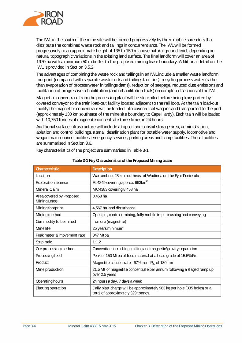
The IWL in the south of the mine site will be formed progressively by three mobile spreaders that distribute the combined waste rock and tailings in concurrent arcs. The IWL will be formed progressively to an approximate height of 135 to 150 m above natural ground level, depending on natural topographic variations in the existing land surface. The final landform will cover an area of 1970 ha with a minimum 50 m buffer to the proposed mining lease boundary. Additional detail on the IWL is provided in Section 3.5.2. The advantages of combining the waste rock and tailings in an IWL include a smaller waste landform footprint (compared with separate waste rock and tailings facilities), recycling process water (rather than evaporation of process water in tailings dams), reduction of seepage, reduced dust emissions and facilitation of progressive rehabilitation (and rehabilitation trials) on completed sections of the IWL. Magnetite concentrate from the processing plant will be stockpiled before being transported by covered conveyor to the train load-out facility located adjacent to the rail loop. At the train load-out facility the magnetite concentrate will be loaded into covered rail wagons and transported to the port (approximately 130 km southeast of the mine site boundary to Cape Hardy). Each train will be loaded with 10,750 tonnes of magnetite concentrate three times in 24 hours. Additional surface infrastructure will include a topsoil and subsoil storage area, administration, ablution and control buildings, a small desalination plant for potable water supply, locomotive and wagon maintenance facilities, emergency services, parking areas and camp facilities. These facilities are summarised in Section 3.6. Key characteristics of the project are summarised in Table 3-1.
Table 3-1 Key Characteristics of the Proposed Mining Lease
Characteristic Description
Location Warramboo, 28 km southeast of Wudinna on the Eyre Peninsula
Exploration Licence EL 4849 covering approx. 663km2
Mineral Claim MC 4383 covering 8,458 ha
Area covered by Proposed Mining Lease
8,458 ha
Mining footprint 4,567 ha land disturbance
Mining method Open pit, contract mining, fully mobile in-pit crushing and conveying
Commodity to be mined Iron ore (magnetite)
Mine life 25 years minimum
Peak material movement rate 347 Mtpa
Strip ratio 1:1.2
Ore processing method Conventional crushing, milling and magnetic/gravity separation
Processing feed Peak of 150 Mtpa of feed material at a head grade of 15.5% Fe
Product Magnetite concentrate - 67% iron, P80 of 130 mm
Mine production 21.5 Mt of magnetite concentrate per annum following a staged ramp up over 2.5 years
Operating hours 24 hours a day, 7 days a week
Blasting operation Daily blast charge will be approximately 983 kg per hole (335 holes) or a total of approximately 329 tonnes.
Chapter 3: Description of the Proposed Mining Operations Mineral Claim 4383 5 Nov 2015 Page 3-5
Characteristic Description
Workforce Site personnel - 1050 during construction phase (including workforce to construct long-term employee village in Wudinna), 560 during operation (260 employees, 300 contractors), 300 for shutdown. Adelaide office – 540 during construction (for CEIP infrastructure and mine) and 60 during operation.
Waste rock and tailings Stacked waste rock and tailings combined in IWL. Progressively stacked to three levels – 45, 90 and 135 m. Radius of stack area 3 - 3.5 km (approximately a semi-circle). Waste rock up to 160 mm diameter and up to approximately 186 Mtpa. Tailings approximately 6.8% moisture and up to approximately 130 Mtpa. Coarse tailings 130 µm - 6 mm. Fine tailings <130 µm. 60% coarse, 40% fine tailings.
Power Approximate peak demand of 2569 GWh per year. Supply from proposed 275 kV transmission line from Yadnarie substation approximately 76 km southeast of the proposed mining lease boundary. The power transmission line is being sought under Iron Road’s Environmental Impact Statement pursuant to the Development Act 1993.
Process water Approximately 12.4 GL per year of saline groundwater from the proposed Kielpa borefield. Commissioning and ramp up of the ore processing facility will require a once off additional quantity of water. The proposed borefield will be located approximately 60 km southeast of the proposed mining lease boundary. A separate approval for the borefield and water pipeline is being sought under Iron Road’s Environmental Impact Statement pursuant to the Development Act 1993.
3.2 Reserves, Products and Market A summary of the geological environment of the mine site, estimated reserves and resources and a description of the product and market is provided in this section of the mining proposal.
3.2.1 Geological Environment
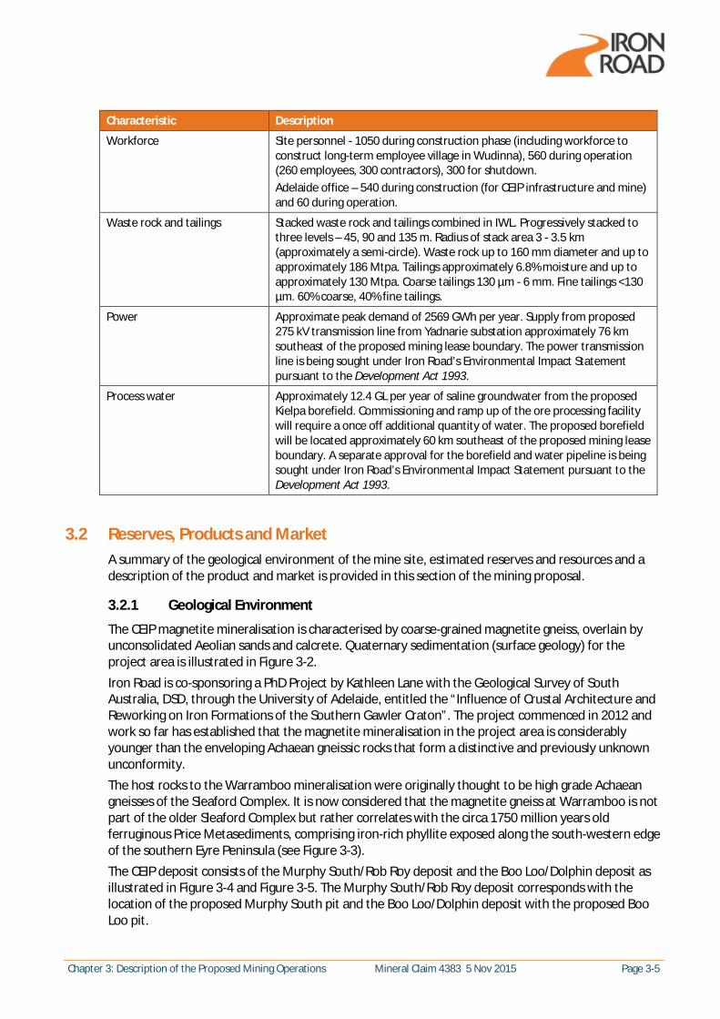
The CEIP magnetite mineralisation is characterised by coarse-grained magnetite gneiss, overlain by unconsolidated Aeolian sands and calcrete. Quaternary sedimentation (surface geology) for the project area is illustrated in Figure 3-2. Iron Road is co-sponsoring a PhD Project by Kathleen Lane with the Geological Survey of South Australia, DSD, through the University of Adelaide, entitled the “Influence of Crustal Architecture and Reworking on Iron Formations of the Southern Gawler Craton”. The project commenced in 2012 and work so far has established that the magnetite mineralisation in the project area is considerably younger than the enveloping Achaean gneissic rocks that form a distinctive and previously unknown unconformity. The host rocks to the Warramboo mineralisation were originally thought to be high grade Achaean gneisses of the Sleaford Complex. It is now considered that the magnetite gneiss at Warramboo is not part of the older Sleaford Complex but rather correlates with the circa 1750 million years old ferruginous Price Metasediments, comprising iron-rich phyllite exposed along the south-western edge of the southern Eyre Peninsula (see Figure 3-3). The CEIP deposit consists of the Murphy South/Rob Roy deposit and the Boo Loo/Dolphin deposit as illustrated in Figure 3-4 and Figure 3-5. The Murphy South/Rob Roy deposit corresponds with the location of the proposed Murphy South pit and the Boo Loo/Dolphin deposit with the proposed Boo Loo pit.

Page 3-6 Mineral Claim 4383 5 Nov 2015 Chapter 3: Description of the Proposed Mining Operations
The Murphy South/Rob Roy iron mineralisation is a large elongate homogeneous south dipping unit (see Figure 3-5). The main strike of the mineralisation is east to west and extends for 6.1 km. The mineralised unit ranges from 100 m to 400 m in width and dips from the top of the fresh zone at 30 degrees to 60 degrees to the South. The dip is steeper in the west and flattens towards the east. The eastern and flatter end contains a pod of internal waste, however petrological indications suggest that it is unrelated to the bounding “barren gneisses” and is possibly a zone of iron depletion in the magnetite gneiss. The main rock types that occur in the Murphy South/Rob Roy prospect are a quartz-feldspar-biotite gneiss “barren gneiss” that envelops the magnetite gneiss and “magnetite gneiss” characterised by quartz-feldspar-magnetite-garnet-biotite. Thin, late stage, dolerite intrusives are also observed in the drill core. The Boo Loo/Dolphin mineralisation is also represented by two main rock types. They are a quartz-feldspar-biotite gneiss or “barren gneiss” that envelops the magnetite-bearing gneiss that consists mainly of quartz-feldspar-magnetite-garnet-biotite. The mineralisation shows greater partitioning in the Boo Loo/Dolphin prospect with the formation of higher grade but thinner discrete lenses. Whilst some of the mineralisation may be open at depth, further delineation will occur as the mine matures. This information informs ongoing management decisions around aspects such as short and long term mine planning, pit back-filling and mine life. Other minor bedrock lithologies present in the drillholes include calcite marble and amphibole-bearing gneiss. Relatively rare, thin dolerite dykes and sills also traverse the area. The local structure of the Boo Loo/Dolphin deposit consists of folding and has had the greatest influence on the current configuration of the gneissic units. The data from structural studies indicates a major synformal fold closure running approximately east-west between Boo Loo and Dolphin and was interpreted based on chemical and structural information.
Chapter 3: Description of the Proposed Mining Operations Mineral Claim 4383 5 Nov 2015 Page 3-7
Figure 3-2 Surface Geology of the Exploration Licence

Page 3-8 Mineral Claim 4383 5 Nov 2015 Chapter 3: Description of the Proposed Mining Operations
Figure 3-3 Geological Age of CEIP Deposit

Chapter 3: Description of the Proposed Mining Operations Mineral Claim 4383 5 Nov 2015 Page 3-9
Figure 3-4 CEIP Orebody
Figure 3-5 Orebody Mineralisation Looking West
3.2.2 Reserves and Resources
The Australasian Joint Ore Reserves Committee (JORC) Code provides a minimum standard for public reporting of exploration results and estimates of mineral resources and ore reserves. Mineral resources may be further divided into Inferred, lndicated and Measured, in order of increasing certainty. An lnferred Resource is that part of the resource for which quantity and grade (or quality) are estimated on the basis of limited geological evidence and sampling. An lnferred Resource can be upgraded to an lndicated Resource with continued exploration. Iron Road reported to the Australian Securities Exchange on 27 February 2015 an updated JORC Code compliant mineral resource of approximately 4.5 billion tonnes (Bt) at a grade of 16% iron. This mineral resource estimate underpins the current mine plan and production schedule for the CEIP mine as well as presenting potential for extending the life of the proposed mine post-25 years (refer to Table 3-2).
Page 3-10 Mineral Claim 4383 5 Nov 2015 Chapter 3: Description of the Proposed Mining Operations
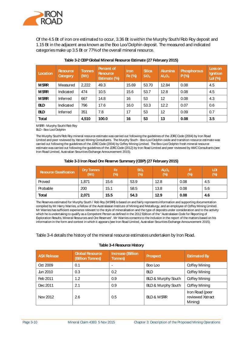
Of the 4.5 Bt of iron ore estimated to occur, 3.36 Bt is within the Murphy South/Rob Roy deposit and 1.15 Bt in the adjacent area known as the Boo Loo/Dolphin deposit. The measured and indicated categories make up 3.5 Bt or 77% of the overall mineral resource.
Table 3-2 CEIP Global Mineral Resource Estimate (27 February 2015)
Location Resource Category
Tonnes (Mt)
Percent of Resource Estimate (%)
Iron Fe (%)
Silica SiO₂
Alumina Al₂O₃
Phosphorous P (%)
Loss on Ignition Lol (%)
MSRR Measured 2,222 49.3 15.69 53.70 12.84 0.08 4.5
MSRR Indicated 474 10.5 15.6 53.7 12.8 0.08 4.5
MSRR Inferred 667 14.8 16 53 12 0.08 4.3
BLD Indicated 796 17.6 16.0 53.3 12.2 0.07 0.6
BLD Inferred 351 7.8 17 53 12 0.09 0.7
Total 4,510 100.0 16 53 13 0.08 3.5
MSRR - Murphy South/Rob Roy BLD - Boo Loo/Dolphin
The Murphy South/Rob Roy mineral resource estimate was carried out following the guidelines of the JORC Code (2004) by Iron Road Limited and peer reviewed by Xstract Mining Consultants. The Murphy South - Boo-Loo/Dolphin oxide and transition resource estimate was carried out following the guidelines of the JORC Code (2004) by Coffey Mining Limited. The Boo-Loo/Dolphin fresh mineral resource estimate was carried out following the guidelines of the JORC Code (2012) by Iron Road Limited and peer reviewed by AMC Consultants (see Iron Road Limited, Australian Securities Exchange Announcement 2015).
Table 3-3 Iron Road Ore Reserve Summary (CEIP) (27 February 2015)
Resource Classification Dry Tonnes (Mt)
Fe (%)
SiO2 (%)
Al2O3 (%)
P (%)
LOI (%)
Proved 1,871 15.6 53.9 12.8 0.08 4.5
Probable 200 15.1 58.5 13.8 0.08 5.6
Total 2,071 15.5 54.3 12.9 0.08 4.6
The Reserves estimated for Murphy South / Rob Roy (MSRR) is based on and fairly represents information and supporting documentation compiled by Mr Harry Warries, a Fellow of the Australasian Institute of Mining and Metallurgy, and an employee of Coffey Mining Limited. Mr Warries has sufficient experience relevant to the style of mineralisation and the type of deposits under consideration and to the activity which he is undertaking to qualify as a Competent Person as defined in the 2012 Edition of the “Australasian Code for Reporting of Exploration Results, Mineral Resources and Ore Reserves”. Mr Warries consents to the inclusion in the report of the matters based on his information in the form and context in which it appears (see Iron Road Limited, Australian Securities Exchange Announcement 2015).
Table 3-4 details the history of the mineral resource estimates undertaken by Iron Road.
Table 3-4 Resource History
ASX Release Global Resource (Billion Tonnes)
Increase (Billion Tonnes) Prospect Estimated By
Oct 2009 0.1 - Boo Loo Coffey Mining
Jun 2010 0.3 0.2 BLD Coffey Mining
Feb 2011 1.2 0.9 BLD & Murphy South Coffey Mining
Dec 2011 2.1 0.9 BLD & Murphy South Coffey Mining
Nov 2012 2.6 0.5 BLD & MSRR Iron Road (peer reviewed Xstract Mining)
Chapter 3: Description of the Proposed Mining Operations Mineral Claim 4383 5 Nov 2015 Page 3-11
ASX Release Global Resource (Billion Tonnes)
Increase (Billion Tonnes) Prospect Estimated By
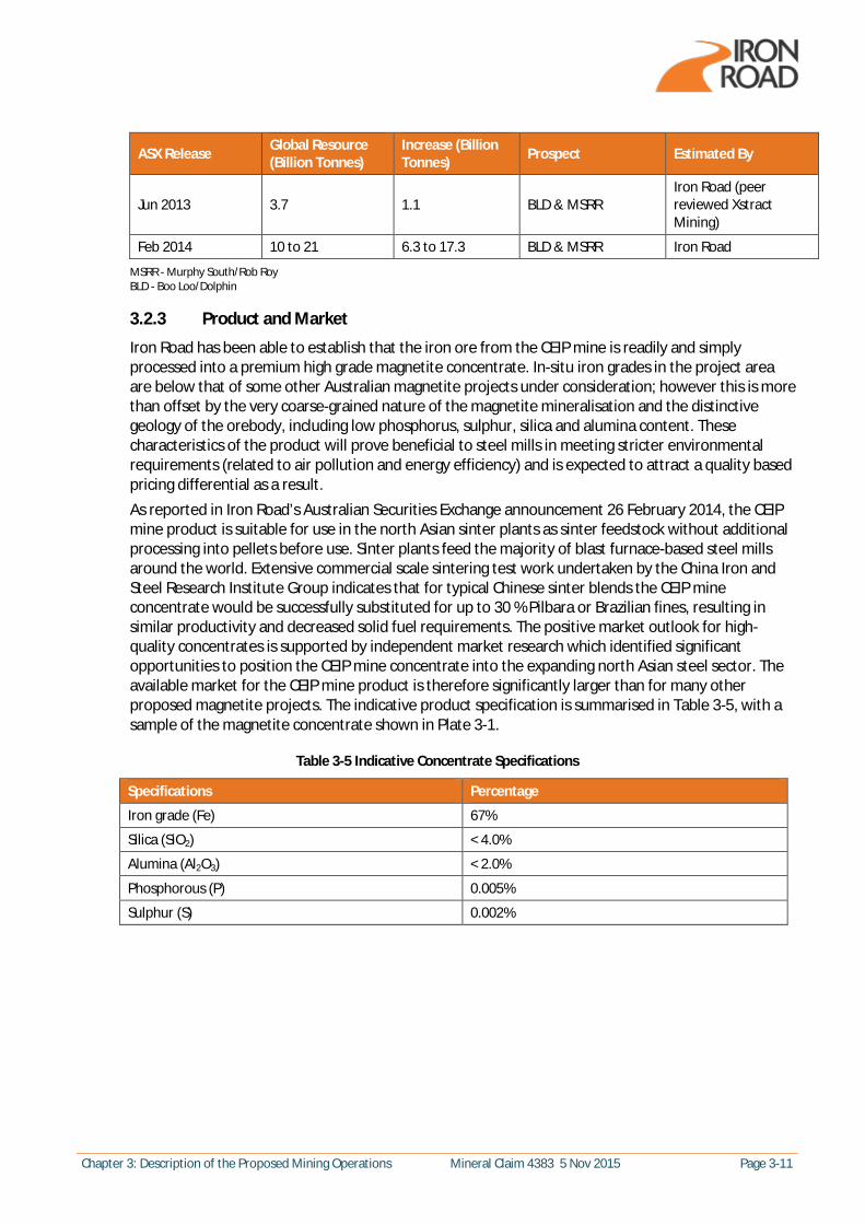
Jun 2013 3.7 1.1 BLD & MSRR Iron Road (peer reviewed Xstract Mining)
Feb 2014 10 to 21 6.3 to 17.3 BLD & MSRR Iron Road
MSRR - Murphy South/Rob Roy BLD - Boo Loo/Dolphin
3.2.3 Product and Market
Iron Road has been able to establish that the iron ore from the CEIP mine is readily and simply processed into a premium high grade magnetite concentrate. In-situ iron grades in the project area are below that of some other Australian magnetite projects under consideration; however this is more than offset by the very coarse-grained nature of the magnetite mineralisation and the distinctive geology of the orebody, including low phosphorus, sulphur, silica and alumina content. These characteristics of the product will prove beneficial to steel mills in meeting stricter environmental requirements (related to air pollution and energy efficiency) and is expected to attract a quality based pricing differential as a result. As reported in Iron Road’s Australian Securities Exchange announcement 26 February 2014, the CEIP mine product is suitable for use in the north Asian sinter plants as sinter feedstock without additional processing into pellets before use. Sinter plants feed the majority of blast furnace-based steel mills around the world. Extensive commercial scale sintering test work undertaken by the China Iron and Steel Research Institute Group indicates that for typical Chinese sinter blends the CEIP mine concentrate would be successfully substituted for up to 30 % Pilbara or Brazilian fines, resulting in similar productivity and decreased solid fuel requirements. The positive market outlook for high-quality concentrates is supported by independent market research which identified significant opportunities to position the CEIP mine concentrate into the expanding north Asian steel sector. The available market for the CEIP mine product is therefore significantly larger than for many other proposed magnetite projects. The indicative product specification is summarised in Table 3-5, with a sample of the magnetite concentrate shown in Plate 3-1.
Table 3-5 Indicative Concentrate Specifications
Specifications Percentage
Iron grade (Fe) 67%
Silica (SiO2) < 4.0%
Alumina (Al2O3) < 2.0%
Phosphorous (P) 0.005%
Sulphur (S) 0.002%

Page 3-12 Mineral Claim 4383 5 Nov 2015 Chapter 3: Description of the Proposed Mining Operations
Plate 3-1 Coarse CEIP Magnetite Concentrate
3.3 Exploration Activities Iron Road has held Exploration Licence (EL) 4849 (formally EL 3699) under the Mining Act 1971 since 2008. EL 4849 contains the Warramboo, Kopi and Hambidge project areas as illustrated in Figure 3-6. The proposed CEIP mine will be located over the Warramboo project area which has been subjected to nine staged resource drilling programmes (incorporating over 500 drill holes) to determine the extent of the iron ore resource. Prior to Iron Road commencing its first exploration drilling programme in 2008, the Warramboo project area had not been subjected to a sustained exploration programme for iron ore. However, several high-level surveys and limited drilling programmes had been completed since the mid-1950s by other parties. An airborne magnetic survey by the Commonwealth Bureau of Mineral Resources (BMR) in 1953-55 located anomalies and defined targets of interest in the region. This was followed by a second airborne survey in 1960, then ground magnetics, gravity surveys and interpretation of resulting data. The former South Australian Department of Minerals and Energy (SADME) also completed a limited drilling programme to evaluate some of the anomalies and subsequently released a detailed report on low grade iron ore deposits on the Eyre Peninsula in 1964. Several companies explored the area intermittently from 1970 but were not focused on iron ore. An aeromagnetic survey was flown in 1994 covering the majority of the magnetic anomalies. The total strike length of magnetic anomalies within the area due to magnetite-bearing gneiss was estimated to be well in excess of 50 km. In 1999 and 2000, with the co-operation of the South Australian Government, Adelaide Resources Limited conducted ground magnetic and gravity surveys over restricted areas within the prospect, drilled six reverse circulation percussion holes totalling 945 m and completed a programme of metallurgical studies further defining the potentially economic iron grades that are present.
Chapter 3: Description of the Proposed Mining Operations Mineral Claim 4383 5 Nov 2015 Page 3-13
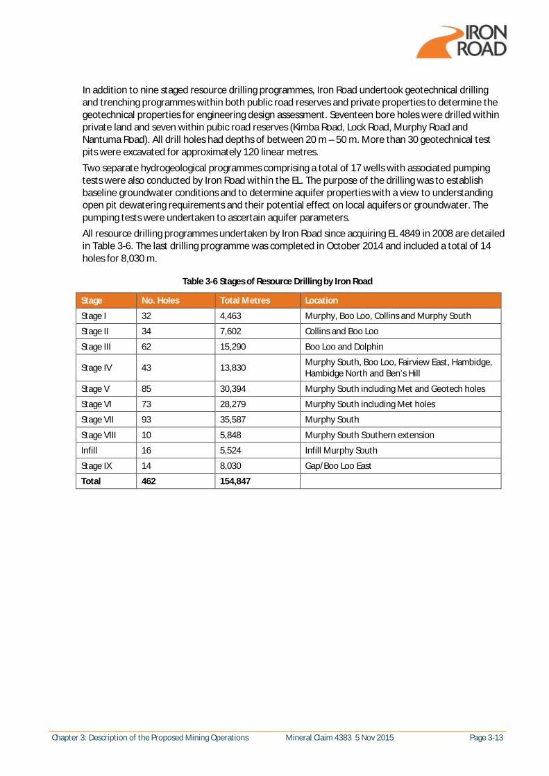
In addition to nine staged resource drilling programmes, Iron Road undertook geotechnical drilling and trenching programmes within both public road reserves and private properties to determine the geotechnical properties for engineering design assessment. Seventeen bore holes were drilled within private land and seven within pubic road reserves (Kimba Road, Lock Road, Murphy Road and Nantuma Road). All drill holes had depths of between 20 m – 50 m. More than 30 geotechnical test pits were excavated for approximately 120 linear metres. Two separate hydrogeological programmes comprising a total of 17 wells with associated pumping tests were also conducted by Iron Road within the EL. The purpose of the drilling was to establish baseline groundwater conditions and to determine aquifer properties with a view to understanding open pit dewatering requirements and their potential effect on local aquifers or groundwater. The pumping tests were undertaken to ascertain aquifer parameters. All resource drilling programmes undertaken by Iron Road since acquiring EL 4849 in 2008 are detailed in Table 3-6. The last drilling programme was completed in October 2014 and included a total of 14 holes for 8,030 m.
Table 3-6 Stages of Resource Drilling by Iron Road
Stage No. Holes Total Metres Location
Stage I 32 4,463 Murphy, Boo Loo, Collins and Murphy South
Stage II 34 7,602 Collins and Boo Loo
Stage III 62 15,290 Boo Loo and Dolphin
Stage IV 43 13,830 Murphy South, Boo Loo, Fairview East, Hambidge, Hambidge North and Ben’s Hill
Stage V 85 30,394 Murphy South including Met and Geotech holes
Stage VI 73 28,279 Murphy South including Met holes
Stage VII 93 35,587 Murphy South
Stage VIII 10 5,848 Murphy South Southern extension
Infill 16 5,524 Infill Murphy South
Stage IX 14 8,030 Gap/Boo Loo East
Total 462 154,847

Page 3-14 Mineral Claim 4383 5 Nov 2015 Chapter 3: Description of the Proposed Mining Operations
Figure 3-6 Aeromagnetic Response of Exploration Licence
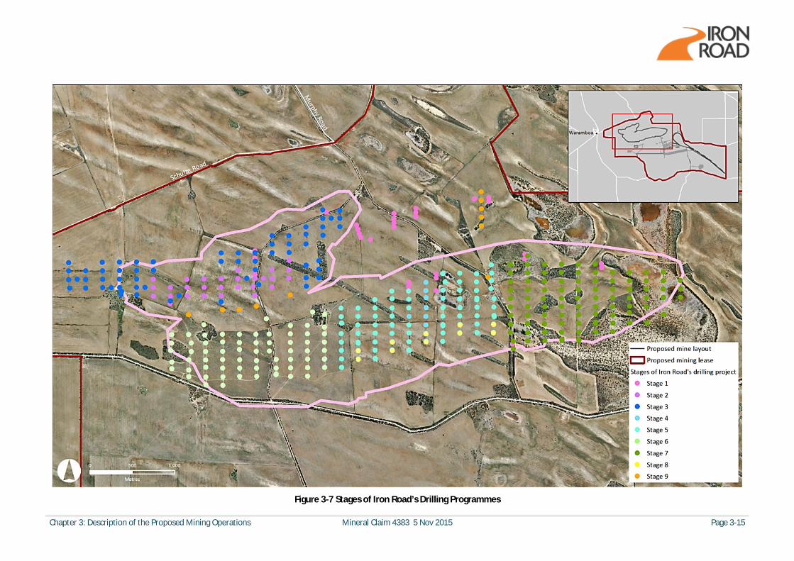
Chapter 3: Description of the Proposed Mining Operations Mineral Claim 4383 5 Nov 2015 Page 3-15
Figure 3-7 Stages of Iron Road’s Drilling Programmes

Page 3-16 Mineral Claim 4383 5 Nov 2015 Chapter 3: Description of the Proposed Mining Operations
3.4 Mining Description
3.4.1 Mining Method
As indicated above, an in-pit crushing and conveying (IPCC) mining operation is proposed using a mining contractor. The IPCC mining method comprises a traditional open pit operation consisting of drilling and blasting followed by direct feed of six fully mobile crushers by large diesel powered excavators at the mine face. The crushers and excavators will move repeatedly back and forth along the mine face excavating either ore or waste rock. Each crusher will feed a track-mounted mobile covered conveyor (similar to Plate 3-2) connected to overland covered conveyers exiting the mine pit. Both ore and waste will be crushed before placement onto the conveyor. Once out of the pit, the material will be batch handled at a conveyor distribution transfer point located between the edge of the pit and the coarse ore stockpiles, to direct ore via covered conveyors to the course ore stockpiles close to the ore processing facility and waste rock via covered conveyors to the IWL. The transfer point will use shuttle head conveyors to direct ore and waste to the correct destination. As the conveyor carrying waste to the IWL passes the ore processing facility, tailings from the ore treatment process will be placed on the waste conveyor. This will facilitate the co-mingling of the waste and tailings for deposition on the IWL by spreaders.
Plate 3-2 Illustration of Excavator Feeding a Fully Mobile Crusher and Track Mounted Conveyor (Source: MMD)
A comparison of the feasibility of conventional truck and shovel mining for the life of the mine versus commencement of IPCC technology following pre-stripping was completed as part of the DFS. It was determined that the nature of the resource ideally suited IPCC and this method will be a more cost-effective option. The advantages and efficiencies of IPCC include a reduced truck fleet, simplified in-pit traffic flow, lower diesel requirements, optimised waste rock disposal and environmental benefits due to reduced diesel use and reduced wheel-generated dust on haul roads. An overview of the mining process is shown in Figure 3-8, with the stages of the proposed mining schedule detailed in Section 3.4.2.

Chapter 3: Description of the Proposed Mining Operations Mineral Claim 4383 5 Nov 2015 Page 3-17
Figure 3-8 Simplified Mining Process Diagram

Page 3-18 Mineral Claim 4383 5 Nov 2015 Chapter 3: Description of the Proposed Mining Operations
3.4.2 Mining Schedule
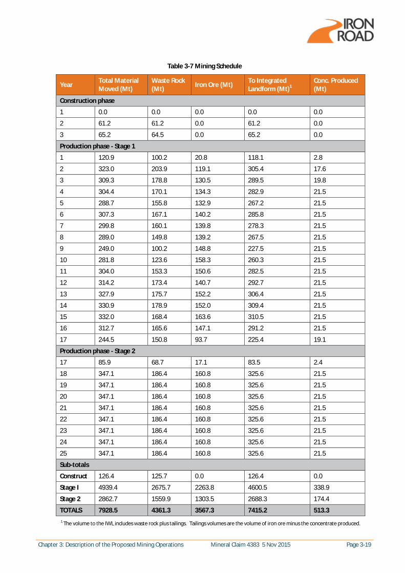
A summary of the proposed mining schedule detailing years of mining and corresponding quantities of material moved, waste and ore is provided in Table 3-7. Movement of top soils and subsoils are discussed in Section 3.4.6. It is proposed that mining will commence in 2020. The mining schedule is based on the following constraints/targets:
· Concentrate production target of 21.5 Mtpa · Maximum ore processing facility throughput of 150 Mtpa · Maximum total material movement of 350 Mtpa · Mining of Boo Loo/Dolphin deposit to be deferred as long as possible · Life of mine of 25 years
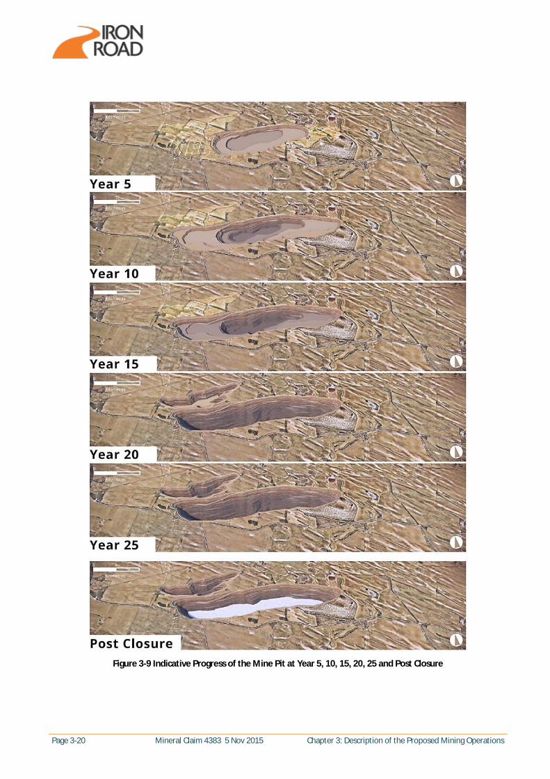
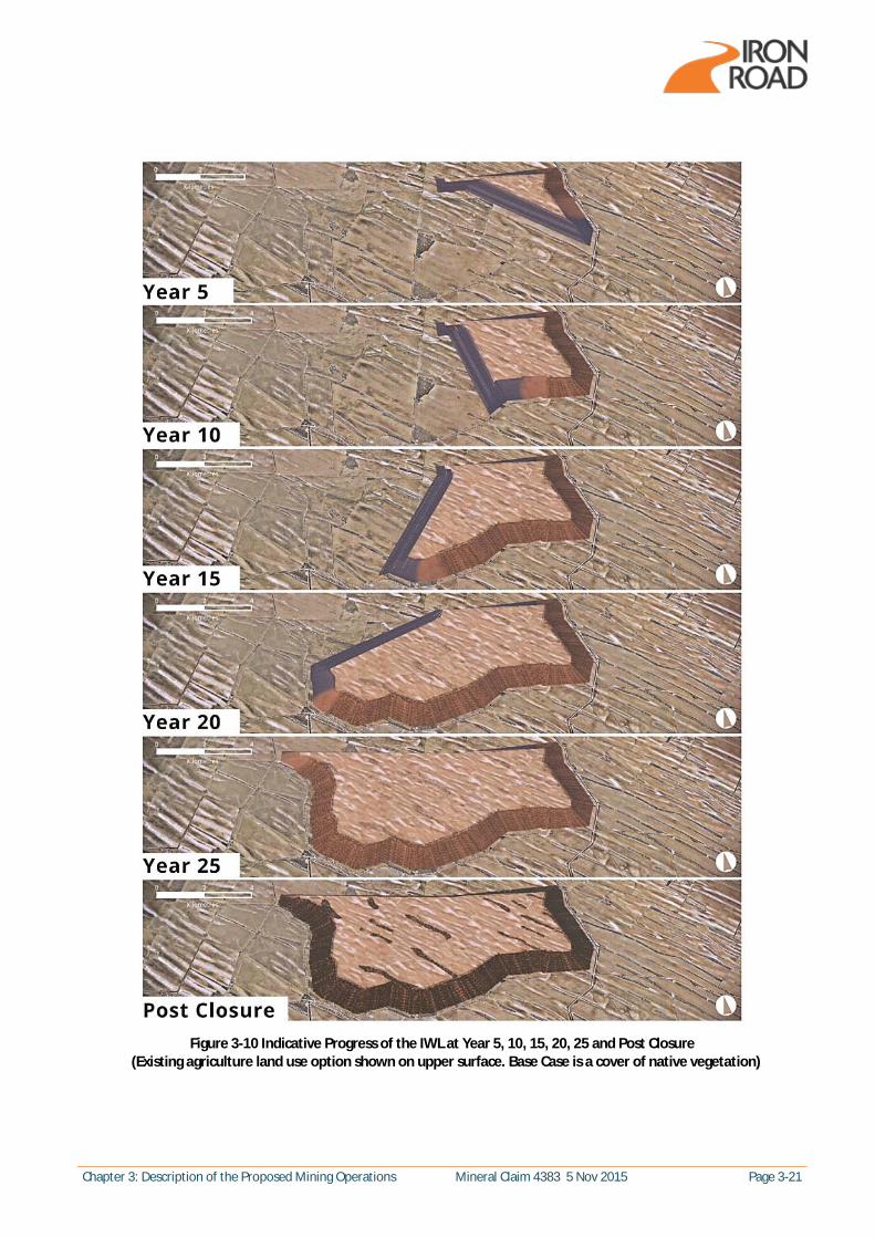
The mining schedule incorporates three years of pre-stripping and surface facilities construction (Construction phase) followed by 25 years of mining (Production phase). It is proposed that the mine will produce 21.5 Mt of magnetite concentrate per annum following a staged ramp up over 2.5 years. The pre-strip to expose the Murphy South/Rob Roy orebody will start in the eastern half of the Murphy South pit area during the Construction phase. Additional Construction phase works are summarised in Section 3.4.3. Mining will remain exclusively in the Murphy South pit until year 17 of production, when pre-stripping of the Boo Loo pit to expose the Boo Loo/Dolphin orebody commences. Ore from the Boo Loo pit is expected from year 17, with both pits in operation up to year 25 of production. Following the Production phase, a mine closure phase will be completed prior to relinquishment of the proposed mining lease at mine completion. The closure phase will involve decommissioning of site infrastructure, final capping and rehabilitation of the IWL and any works required to stabilise the mine pit and prevent unauthorised entry. At mine completion it has been estimated that the Murphy South pit will be approximately 6.2 km long, 1.4 km wide and 630 m deep and the Boo Loo pit will be approximately 3 km long, 1 km wide and 325 m deep. Additional details on mine completion are provided in Section 3.7. Graphics illustrating the indicative progress of the mine pit and IWL at years 5, 10, 15, 20, 25 and post closure are provided in Figure 3-9 and Figure 3-10.
Chapter 3: Description of the Proposed Mining Operations Mineral Claim 4383 5 Nov 2015 Page 3-19
Table 3-7 Mining Schedule
Year Total Material Moved (Mt)
Waste Rock (Mt) Iron Ore (Mt) To Integrated
Landform (Mt)1 Conc. Produced (Mt)
Construction phase
1 0.0 0.0 0.0 0.0 0.0
2 61.2 61.2 0.0 61.2 0.0
3 65.2 64.5 0.0 65.2 0.0
Production phase - Stage 1
1 120.9 100.2 20.8 118.1 2.8
2 323.0 203.9 119.1 305.4 17.6
3 309.3 178.8 130.5 289.5 19.8
4 304.4 170.1 134.3 282.9 21.5
5 288.7 155.8 132.9 267.2 21.5
6 307.3 167.1 140.2 285.8 21.5
7 299.8 160.1 139.8 278.3 21.5
8 289.0 149.8 139.2 267.5 21.5
9 249.0 100.2 148.8 227.5 21.5
10 281.8 123.6 158.3 260.3 21.5
11 304.0 153.3 150.6 282.5 21.5
12 314.2 173.4 140.7 292.7 21.5
13 327.9 175.7 152.2 306.4 21.5
14 330.9 178.9 152.0 309.4 21.5
15 332.0 168.4 163.6 310.5 21.5
16 312.7 165.6 147.1 291.2 21.5
17 244.5 150.8 93.7 225.4 19.1
Production phase - Stage 2
17 85.9 68.7 17.1 83.5 2.4
18 347.1 186.4 160.8 325.6 21.5
19 347.1 186.4 160.8 325.6 21.5
20 347.1 186.4 160.8 325.6 21.5
21 347.1 186.4 160.8 325.6 21.5
22 347.1 186.4 160.8 325.6 21.5
23 347.1 186.4 160.8 325.6 21.5
24 347.1 186.4 160.8 325.6 21.5
25 347.1 186.4 160.8 325.6 21.5
Sub-totals
Construct 126.4 125.7 0.0 126.4 0.0
Stage I 4939.4 2675.7 2263.8 4600.5 338.9
Stage 2 2862.7 1559.9 1303.5 2688.3 174.4
TOTALS 7928.5 4361.3 3567.3 7415.2 513.3 1 The volume to the IWL includes waste rock plus tailings. Tailings volumes are the volume of iron ore minus the concentrate produced.
Page 3-20 Mineral Claim 4383 5 Nov 2015 Chapter 3: Description of the Proposed Mining Operations
Figure 3-9 Indicative Progress of the Mine Pit at Year 5, 10, 15, 20, 25 and Post Closure
Chapter 3: Description of the Proposed Mining Operations Mineral Claim 4383 5 Nov 2015 Page 3-21
Figure 3-10 Indicative Progress of the IWL at Year 5, 10, 15, 20, 25 and Post Closure
(Existing agriculture land use option shown on upper surface. Base Case is a cover of native vegetation)

Page 3-22 Mineral Claim 4383 5 Nov 2015 Chapter 3: Description of the Proposed Mining Operations
3.4.3 Construction Phase Summary
Key aspects of the Construction phase works include:
· Upgrades of a number of roads to be used to access the mine site as summarised in Section 3.6.1. · Earthworks and construction of surface infrastructure within the mine site as summarised below. · Commencement of pre-stripping and construction of the ramp at the IWL to allow installation of
the mobile spreaders as summarised below. · Module delivery and installation including processing plant and concentrate handling
infrastructure as summarised below.
An indicative construction schedule is provided in Figure 3-11 and further details are provided below.
Figure 3-11 Indicative Construction Schedule
Earthworks, Surface Infrastructure Construction and Module Installation
The initial focus of the earthworks and construction within the mine site will be on the first stage of the construction camp to provide accommodation for construction contractors, followed by internal road construction, commencement of earthworks in preparation for module delivery, water supply infrastructure and other buildings/facilities. Iron Road intends to use modular construction methods for large scale infrastructure and buildings including the crushers, conveyors, transfer stations, ore processing facility components and concentrate handling facility components. This method involves the majority of the construction work being undertaken at an off-shore pre-assembly yard and shipping the substantially completed assemblies to the proposed module offloading facility at the proposed port using lift on/lift off and roll on/roll off ships. To facilitate delivery of the modules from the proposed port to the mine road, upgrades will need to be completed along the module route. Further information in relation to the module route and road upgrades is provided in Chapter 8 Traffic. Earthworks will be required prior to arrival of the modules with different module types requiring particular site preparation from level compacted ground for modules that have precast concrete foundations to construction of concrete foundations on site for other modules. A concrete batching plant will be in operation on site to supply all concrete requirements as required for construction.
Chapter 3: Description of the Proposed Mining Operations Mineral Claim 4383 5 Nov 2015 Page 3-23
Construction of roads, turkey nests, stockpile hardstands and smaller buildings (such as offices, ablution and change rooms and the explosive storage facility) will also be completed during the Construction phase. Additional detail on these facilities is provided in Section 3.6.
Pre-stripping and Construction of the IWL Ramp
Pre-stripping (removal of overburden) to expose the orebody will start in the eastern half of the Murphy South pit area during the construction phase and continue into the production phase as required to enable access to the orebody. Pre-stripping will be deferred for as long as practicable, with approximately 50 % of the Murphy South pit pre-stripped by year 5 of production (see Figure 3-9 above). The pre-strip rate is expected to be approximately 10 % per year during the 3 year construction phase and the first two years of production phase, then slowing to approximately 2 % per year during subsequent years. Pre-stripping of the Boo Loo pit is not anticipated until year 17 of production. Overburden to be removed ranges in depth across the pit area from approximately 30-60 m. Pre-stripping will be completed by conventional truck and shovel, load and haul method within the mine pit area. Six large diesel powered excavators (nominally Liebherr R 9800) and 12 360 tonne haul trucks will undertake the pre-strip. Topsoil and subsoil depth across the pit area varies and both represent a valuable resource for rehabilitation of the IWL. Topsoil will be removed from beneath site infrastructure and pre-stripped from the mine pit as the pit progresses and stockpiled for future use during rehabilitation works. It will be delivered to the topsoil temporary storage area by truck. Subsoils from the mine pit pre-strip will be used initially in the development of ramps to establish the IWL conveyors and subsequently in the establishment of the cover profile for the IWL. A material balance for both topsoils and subsoils is provided in Section 3.4.6. Excavated material (predominately waste rock) to be transported to the IWL will be delivered by trucks to a temporary stockpile area at the edge of the pit area. One conveyor stream from the edge of the mine pit area to the IWL will be in operation to deliver the excavated waste rock during pre-strip to the IWL. Transfer stations will be used to transfer waste rock from one conveyor to the next. These will be enclosed and have dust extraction and filtration units fitted to minimise dust emissions. Initially waste rock and subsoils delivered to the IWL will be worked by dozers to construct the first IWL spreader ramp. Once the ramp is constructed, the first IWL spreader will be positioned and allow efficient delivery of the waste rock to form the IWL. Water trucks will be operating during the pre-stripping operation to minimise dust emissions. However the use of saline water for dust suppression during the stripping of topsoil containing native seedbanks will be avoided where practicable to preserve any native seedbank that may occur. Additional desalinated water will be sourced from the temporary construction RO plant for dust suppression use on soils to be used as IWL cover materials.
3.4.4 Use of Explosives
Blasting Operation
Explosives will be used for blasting operations in the mine pit. Blasting will break the iron ore and waste rock into loose material that allows the mining equipment to readily excavate it for loading directly into the mobile crushers.
Page 3-24 Mineral Claim 4383 5 Nov 2015 Chapter 3: Description of the Proposed Mining Operations
In the mine pit, the orebody will be drilled and blasted in benches. The blast holes will be drilled by a fleet of production drill rigs in a ‘pattern’ in an area of the bench identified for blasting. The pattern comprises evenly-spaced rows of drill holes set out in a specific pattern and depth. The proposed blasting operation includes operating two benches daily with a bench width of 15 m and drilling approximately 335 holes per day with a diameter of 310 mm at 9 m spacing. The drill rig fleet will comprise 20 D90K and seven PV271 drill rigs with 10 drill rigs in operation on each bench each day. The 20 drill rigs will operate at 90% utilisation. Approximately 983 kg of explosive will be put into each individual blast hole. Once all holes have been charged, they are connected together to explode in a certain sequence. Blasting is done on a hole-by-hole basis – no two holes are blasted at exactly the same time. This process not only presents optimum blasting performance but also helps reduce airblast noise and ground vibration. Blasting will take place once per day during daylight hours at a regular time advised to the local community.
Explosives Storage and Manufacturing Facility
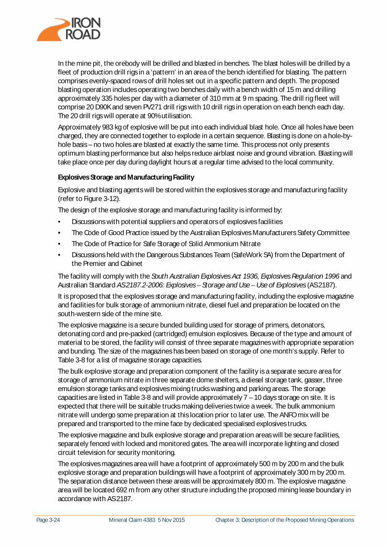
Explosive and blasting agents will be stored within the explosives storage and manufacturing facility (refer to Figure 3-12). The design of the explosive storage and manufacturing facility is informed by:
· Discussions with potential suppliers and operators of explosives facilities · The Code of Good Practice issued by the Australian Explosives Manufacturers Safety Committee · The Code of Practice for Safe Storage of Solid Ammonium Nitrate · Discussions held with the Dangerous Substances Team (SafeWork SA) from the Department of
the Premier and Cabinet
The facility will comply with the South Australian Explosives Act 1936, Explosives Regulation 1996 and Australian Standard AS 2187.2-2006: Explosives – Storage and Use – Use of Explosives (AS 2187). It is proposed that the explosives storage and manufacturing facility, including the explosive magazine and facilities for bulk storage of ammonium nitrate, diesel fuel and preparation be located on the south-western side of the mine site. The explosive magazine is a secure bunded building used for storage of primers, detonators, detonating cord and pre-packed (cartridged) emulsion explosives. Because of the type and amount of material to be stored, the facility will consist of three separate magazines with appropriate separation and bunding. The size of the magazines has been based on storage of one month’s supply. Refer to Table 3-8 for a list of magazine storage capacities. The bulk explosive storage and preparation component of the facility is a separate secure area for storage of ammonium nitrate in three separate dome shelters, a diesel storage tank, gasser, three emulsion storage tanks and explosives mixing trucks washing and parking areas. The storage capacities are listed in Table 3-8 and will provide approximately 7 – 10 days storage on site. It is expected that there will be suitable trucks making deliveries twice a week. The bulk ammonium nitrate will undergo some preparation at this location prior to later use. The ANFO mix will be prepared and transported to the mine face by dedicated specialised explosives trucks. The explosive magazine and bulk explosive storage and preparation areas will be secure facilities, separately fenced with locked and monitored gates. The area will incorporate lighting and closed circuit television for security monitoring. The explosives magazines area will have a footprint of approximately 500 m by 200 m and the bulk explosive storage and preparation buildings will have a footprint of approximately 300 m by 200 m. The separation distance between these areas will be approximately 800 m. The explosive magazine area will be located 692 m from any other structure including the proposed mining lease boundary in accordance with AS 2187.
Chapter 3: Description of the Proposed Mining Operations Mineral Claim 4383 5 Nov 2015 Page 3-25
Figure 3-12 Explosives Storage and Manufacturing Facility

Page 3-26 Mineral Claim 4383 5 Nov 2015 Chapter 3: Description of the Proposed Mining Operations
Table 3-8 Explosives Storage and Manufacturing Facility Capacities
Storage area Capacity
Explosive magazine
Primers, detonators, detonating cord Three 50 t magazines
Pre-packed emulsion explosives One 10 t magazine
Bulk explosive storage and preparation area
Ammonium nitrate 500 t bulka bag storage in each of the three dome shelters (Total 1500 t)
Diesel fuel 68 kL storage tank
Emulsion Three 320 t emulsion storage tanks (Total 960 t)
Preparation and Placement of Explosives
Explosives will be delivered to the predrilled blasting area of the mine in standard Mobile Processing Units (MPU). An MPU is defined as a vehicle-mounted plant which carries its own ingredients, manufactures or blends a Class 1 explosive and contains its own delivery system for the explosive, or a vehicle-mounted bulk explosives container which contains its own delivery system for the explosive. An important design feature of MPU types intended for use at the CEIP mine is that the explosive product is manufactured as part of the delivery system, which means that all vehicle-manufactured explosive is removed from the vehicle immediately following manufacture and apart from minor residues the vehicle carries no explosive material. The following MPUs are considered for the mine blasting operations:
· ANFO Units - ANFO units mix ammonium nitrate prills and a combustible liquid, usually diesel oil, to form an explosive. Extra ingredients such as aluminium powder and polystyrene beads may also be added. The mixing process is typically via a mixing auger. The delivery system is usually an auger, a slide or a pneumatic blow-loading arrangement.
· Emulsion Units - Typically, these vehicles carry ammonium nitrate emulsion, ammonium nitrate and fuel oil in containers. These are mixed on the MPU to produce the explosive. Additional materials (e.g. “effect chemicals”) may be added to modify the properties of the explosive. Typically these units can produce a range of explosives by varying the ratios of the ingredients.
· Pre-blended ANFO Units - Typically, these vehicles contain a bulk container of blended ANFO and a system for delivering the ANFO directly to the blast holes.
3.4.5 Type of Equipment
The mining contractor’s vehicle and equipment fleet may vary during the life of the mine, however an indicative equipment list is provided in Table 3-9. The potential dust and exhaust emissions from the equipment fleet was assessed in the Air Quality Impact Assessment Report which is provided in Appendix K and summarised in Chapter 15. The potential noise and vibration generated by the equipment fleet was assessed as part of the Environmental Noise and Vibration Assessment Report which is provided in Appendix L and summarised in Chapter 16 and 17.

Chapter 3: Description of the Proposed Mining Operations Mineral Claim 4383 5 Nov 2015 Page 3-27
Table 3-9 Indicative Mobile Fleet
Equipment Description Number of Units – Construction
Number of Units – Production
Tracked excavator – Liebherr R9800 6 7
Modified pipe layers - 4
Haul Trucks – 360T Ultra Class 12 -
Haul Trucks – 240T Class 2 2
Caterpillar – CAT 944H Loader 1 1
Bulldozer – CAT D11 6 6
Bulldozer – CAT D10 4 4
Dozer – Wheel 3 3
Grader – 24M 6 6
Grader – 16M 1 1
Water Truck – 135 kL 5 5
Water Truck – 85 kL 2 2
Diesel Generators 3 -
Cranes 3 -
Drill Rig – Sandvik D90K - 20
Drill Rig – Atlas Copco PV271 - 7
3.4.6 Stockpiles
The following stockpiles will be required within the proposed mining lease:
· Topsoil stockpiles – two separate topsoil stockpiles will be required; one for the storage of native seedbank topsoil and one for agriculture topsoils (potentially including other materials useful for progressive rehabilitation of the IWL, including clay material).
· A subsoil stockpile – for storage of pre-stripped subsoils required for the progressive rehabilitation of the IWL.
· Coarse ore stockpiles – three stockpiles of coarse ore will be located north of the ore processing facility for storage of iron ore conveyed from the mine pit prior to it being reclaimed for processing.
· Concentrate stockpile – for storage of concentrate from the processing plant prior to it being reclaimed for loading onto trains.
An option exists which requires no stockpiling of subsoils, where initial subsoils generated are used in the generation of IWL ramps or disposed of into the IWL. Subsequent subsoil material which is generated from the mine pit pre-strip will be immediately deployed directly onto the IWL cover profile as the IWL develops to enable progressive rehabilitation and any shortfall in subsoil material once the mine pit is fully stripped would come from pre-stripping in front of the landform as it develops. The location of each of the stockpiles listed above is shown on Figure 3-1.
Page 3-28 Mineral Claim 4383 5 Nov 2015 Chapter 3: Description of the Proposed Mining Operations
Topsoil Temporary Storage Area
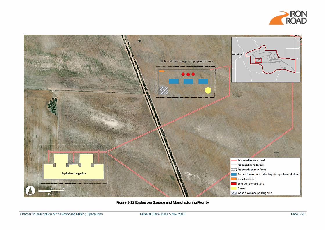
A topsoil temporary storage area will be located on the northern edge of the final footprint of the IWL which will consist of two separate topsoil stockpiles, one for topsoils containing native seed bank and one for agricultural topsoil. The native seed topsoil stockpile will be generated largely during the construction phase to collect and protect the valuable native vegetation seedbank material from beneath all site infrastructure, then progressively from the mine pit pre-strip and progressively from in front of the IWL as it progresses. The native seedbank stockpile will be a maximum height of 2 m (to maintain seedbank quality) and will cover an area of approximately 814 m by 814 m assuming all material is stored with no draw-down. Under a modelled draw-down scenario where native seedbank topsoil is progressively used on the IWL, the maximum size of the native seedbank topsoil stockpile is an area covering 538 m by 538 m. The agricultural topsoil stockpile will be generated progressively during the project as topsoil is removed during the progressive pre-strip of the mine pits (with the Boo Loo pit commencing pre-strip by year 17 of the Production phase). The agricultural topsoil stockpile will be a maximum height of 10 m and will cover a maximum area of 414 m by 414 m, assuming no progressive drawdown of materials. In reality, agricultural topsoil would be used progressively throughout the life of mine in the IWL surface covering for rehabilitation and modelling of this scenario indicates a peak agricultural topsoil stockpile size of 194 m by 194 m. Locations of both stockpiles are shown on Figure 3-1 with details of each summarised below in Table 3-10 below. Section 3.5.2 presents further details around the material balance for topsoil (i.e the requirements vs availability).
Table 3-10 Topsoil Temporary Storage Area
Material Maximum stockpile volume (m3)
Maximum stockpile area (m2)
Maximum stockpile height (m)
Stockpile square side dimension (m)
Topsoil – Native seedbank (no draw-down) 1,320,000 663,252 2 814
Topsoil – Native seedbank (draw-down scenario) 574,444 289,369 2 538
Topsoil – Agricultural (no draw-down) 1,630,000 171,140 10 414
Topsoil – Agricultural (draw-down scenario) 338,519 37,596 10 194
The topsoil storage area would be used during the life of the mine to store topsoils excavated during ongoing pre-stripping. The soil material will be used for rehabilitation works across the mine site, in particular on the IWL. The preferred method of use for recovered topsoil is to transfer it directly to suitable sites that have been prepared and are ready for progressive rehabilitation. However, where this is not possible, native seedbank stockpiles would be managed at a maximum height of approximately 2 m to preserve the viability of the seed bank and to maintain the soil properties. Agricultural topsoil is expected to be stored for shorter periods of time as it is progressively stripped and used in the surface cover of the IWL. There are no restrictions on the height at which this material can be stored. A height of 10 m has been adopted for planning purposes. Stockpiles will be protected from wind erosion utilising mulch or similar to minimise dust losses.
Chapter 3: Description of the Proposed Mining Operations Mineral Claim 4383 5 Nov 2015 Page 3-29
An inventory of topsoil will be developed for the storage area, detailing:
· Original location of the topsoil · Expected seedbank (native versus exotic) properties within stockpiles · The volume of topsoil stockpiled · Individual stockpile locations within the storage area
Water runoff from the stockpiles will be directed to side swales and collector drains surrounding the storage area and a sedimentation pond at the low point. Water will evaporate from the sediment pond and the sedimentation pond will be cleaned out as required. Overland flow will be directed around the storage area and follow natural drainage lines.
Subsoils
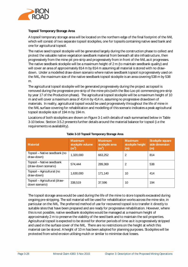
Subsoils also represent a valuable resource for the proposed mine operation and are important for the successful rehabilitation of the IWL. A subsoil stockpile will be generated progressively during the project as topsoil is removed during the progressive pre-strip of the mine pits (with the Boo Loo pit commencing pre-strip by year 17 of the Production phase). The subsoil stockpile will be a maximum height of 10 m and will cover a maximum area of 874 m by 874 m, assuming progressive drawdown of materials. This stockpile could be removed all together if early subsoils which are generated by the mine pre-strip are disposed of into the IWL (in ramp generation and into the IWL) and future subsoil requirements are met by progressive pre-stripping in front of the IWL as it is formed, with material stripped being placed directing into the cover profile. This will be the subject of further optimisation studies prior to the commencement of pre-stripping. The location of the subsoil stockpile is shown on Figure 3-1 with details of the stockpile summarised below in Table 3-11 below.
Table 3-11 Subsoil Stockpile Summary
Material Maximum stockpile volume (m3)
Maximum stockpile area (m2)
Maximum stockpile height (m)
Stockpile square side dimension (m)
Subsoil (assuming drawdown) 7,470,370 764,390 10 874
Section 3.5.2 presents the requirements for subsoils (and topsoils) on the IWL, data regarding the volume of material available and a material balance demonstrating how materials will be moved. There is no requirement to stockpile subsoils at the site as all subsoils are progressively used as they are generated via the pre-stripping process.
Coarse Ore Stockpiles
The conveyors from the conveyor distribution point will deliver iron ore to the three coarse ore stockpiles. The stockpiles will have approximate diameters of 150 m and be located on compacted earth pads. Each stockpile will cover an area of approximately 18,000 m2, have a maximum height of 60 m, diameter of 170 m and contain approximately 500,000 t of iron ore. The stockpiles will comprise sufficient iron ore for approximately 1 day of processing per train. Ore will be reclaimed from the stockpile automatically by an under draw reclaimer under the stockpile and be conveyed through the reclaim tunnel to the ore processing facility. Each stockpile will have a live capacity of 72,000 t, sufficient for 9 hours of operation.
Page 3-30 Mineral Claim 4383 5 Nov 2015 Chapter 3: Description of the Proposed Mining Operations
Concentrate Stockpile
The stockyard that incorporates the concentrate stockpile will be located on the south-eastern side of the mine pit, between the ore processing facility and the rail loop. The stockyard will be approximately 83 m wide and 620 m long, running in an east to west orientation as shown on Figure 3-1. The stockpile capacity will be 360,000 t and the design provides a 44 m wide depressed area, effectively bunding the concentrate, with a 14.5 m wide raised berm on the reclaim side and a 24 m wide raised berm on the stacker side, that both accommodate associated machines. This pad is nominally graded at 0.2% longitudinally to allow some longitudinal drainage, whilst maintaining workable grades for the stacker and reclaimer machines. A single travelling, luffing and slewing stacker mounted on rails will be used to load the stockpile at a rate of 2,900 t/h. The magnetite concentrate will be reclaimed by a bi-directional bridge bucket wheel reclaimer, also mounted on rails, at an average rate of 8,000 t/h. The concentrate stockpile is orientated such that the majority of the adjacent land grades away. As a result of this, there are only some short hillside cuttings that require protecting from overland runoff by constructing interception drains along the high side, thus sheading the runoff around and preventing inundation of the stockpile from external flows. Water trucks will be used to minimise dust from the stockpiles during stacking and reclaiming activities. Water runoff from the stockpile will be directed to side swales and collector drains surrounding the stockpile pad and a sedimentation pond at the low point. Water will evaporate from the sediment pond and the sedimentation pond will be cleaned out as required.
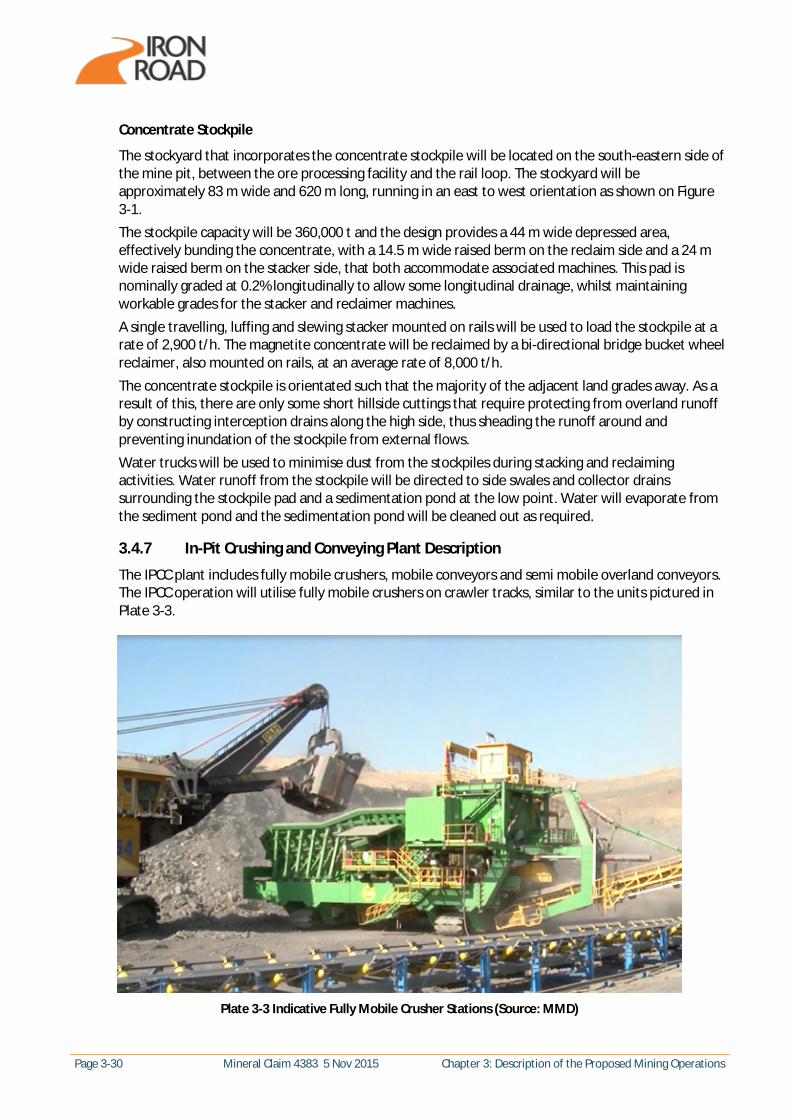
3.4.7 In-Pit Crushing and Conveying Plant Description
The IPCC plant includes fully mobile crushers, mobile conveyors and semi mobile overland conveyors. The IPCC operation will utilise fully mobile crushers on crawler tracks, similar to the units pictured in Plate 3-3.
Plate 3-3 Indicative Fully Mobile Crusher Stations (Source: MMD)

Chapter 3: Description of the Proposed Mining Operations Mineral Claim 4383 5 Nov 2015 Page 3-31
The crusher selection is based on the following factors:
· Type and maximum feed size of material(s) to be crushed · Maximum material strengths and breakage characteristics · Required material gradation · Relocation requirements · Economical operation without excessive maintenance costs · Desired crushing capacity
Different types of crushers such as double-roll crushers, twin shaft sizers, jaw breaker, gyratory and cone crushers and impact crushers, are common in the mining industry and were considered. A gyratory crusher has been chosen as the most suitable equipment for the CEIP magnetite gneiss at the required crushing capacities. The crusher specifications are listed in Table 3-12.
Table 3-12 Mobile Primary Crusher Specifications
Specification Data
Nominal average capacity 10,500 t/h
Input feed size of material (max) 1,200 mm
Output size of material P80 ≤ 160 mm
Total power installed Approx. 1,200 kW
Nominal dimensions 56.2 m x 12.9 m x 14 m
Nominal mass 1350 t
Relocation of plant Fully mobile
Six fully mobile crushers will be located in the mine pit. Excavators at the mine face will direct feed to the crushers and both the excavators and crushers will move repeatedly back and forth along the mine face excavating either ore or waste rock. Each crusher will feed a track-mounted mobile covered conveyor connected to semi mobile overland covered conveyers exiting the mine pit. Once out of the pit, the material will be batch handled at the conveyor distribution point, located between the edge of the pit and the coarse ore stockpiles, to direct ore via covered conveyors to the course ore stockpiles close to the ore processing facility and the waste rock via covered conveyors to the IWL. All conveyors on the mine site will be covered to contain the material being moved and avoid dust escape. Transfer stations are included in the conveyor system design to enclose the transfer points where the conveyor changes direction. The change of direction requires transfer of material from one conveyor to another via a transfer chute. Dust extraction units fitted to the transfer stations will capture dust generated inside the transfer chute. The overland conveyor flights, connecting the mobile conveyors in the mine pit with the conveyor distribution point, will be re-locatable by modified pipe layers. Each conveyor will exit the mine pit on ramps at a gradient of 10 degrees. Separate vehicle ramps are required as the conveyor gradient is too steep for the mobile fleet (mobile fleet ramps need to have a gradient of no more than 6 degrees). The potential dust and exhaust emissions from the IPCC plant was assessed in the Air Quality Impact Assessment Report which is provided in Appendix K and summarised in Chapter 15. The potential noise and vibration generated by the IPCC plant was assessed as part of the Environmental Noise and Vibration Assessment Report which is provided in Appendix L and summarised in Chapter 16 and 17.

Page 3-32 Mineral Claim 4383 5 Nov 2015 Chapter 3: Description of the Proposed Mining Operations
3.4.8 Ore Processing Facility Description
The modularised ore processing facility will be constructed on the south-east edge of the mine pit, between the coarse ore stockpiles and the IWL and will cover an area of approximately 460 m by 480 m. The facility will comprise three identical processing streams including crushing, grinding and recovery to provide a high level of plant availability and to minimise operational downtime. The components of each processing train will include:
· Semi-Autogenous Grinding (SAG) mill for secondary crushing · Rougher Magnetic Separator (RMS) building for low intensity magnetic separation · Ball mill for grinding of rougher concentrate · Cleaner Magnetic Separator (CMS) building containing Derrick screens, CMS units, concentrate
filters and concentrate storage tanks for recovering clean magnetite and storing concentrate · Gravity building for gravity recovery of coarse magnetite · Regrind circuit (verti mill) for grinding and recovery of magnetite from middlings fraction from
gravity section · Tailings thickener (dewatering) · Tailings filter building · Tailings storage tanks
The ore processing facility will treat up to 150 Mtpa of iron ore at a head grade of 15.5% Fe. It has been designed to operate 24 hours a day, seven days a week and produce up to 21.5 Mtpa of magnetite concentrate with a relatively coarse size distribution, P80 of 130 mm and with the following specifications:
· Iron grade (Fe) 67% · Silica (SiO2) < 4% · Alumina (Al2O3) < 2% · Phosphorous (P) 0.005% · Sulphur (S) 0.002%
A simplified process diagram for one process train of the ore processing facility is shown in Figure 3-14. Water used in the processing of the ore will be saline groundwater and will be recycled in the process. The final treatment of the concentrate will involve washing with desalinated water to remove salts from the concentrate. The tailings will have a moisture content of approximately 6.8%. The filtered tailings, with the consistency of damp sand, are transferred to conveyor, combined with the waste rock from the mine and spread on the IWL. A representation of the processing facility is shown in Figure 3-13 and the dimensions of each process building are listed in Table 3-13.

Chapter 3: Description of the Proposed Mining Operations Mineral Claim 4383 5 Nov 2015 Page 3-33
Figure 3-13 Ore Processing Plant Layout
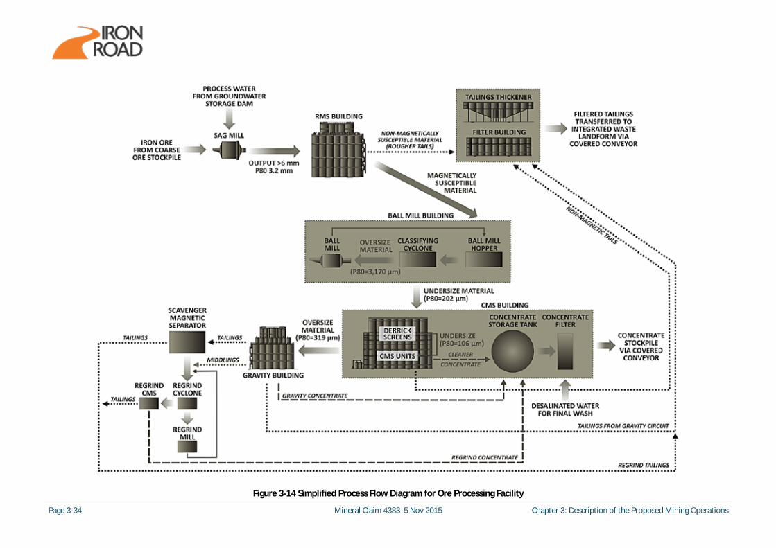
Page 3-34 Mineral Claim 4383 5 Nov 2015 Chapter 3: Description of the Proposed Mining Operations
Figure 3-14 Simplified Process Flow Diagram for Ore Processing Facility

Chapter 3: Description of the Proposed Mining Operations Mineral Claim 4383 5 Nov 2015 Page 3-35
A summary of the process illustrated in Figure 3-14 is provided below:
· Iron ore is transferred by conveyor to the SAG mill for secondary crushing which reduces the feed from approximately 160 mm to less than 6 mm, P80 of 3.2 mm. Process water is added during crushing in the SAG mill and the discharge feed is then pumped as slurry to the RMS building.
· The RMS process involves low intensity magnetic separation which separates the magnetically susceptible component (rougher concentrate) from the non-magnetically susceptible material. The non-magnetically susceptible material (rougher tail) is waste and represents approximately 60% of the feed mass which goes to tailings.
· The rougher concentrate is pumped to the Ball mill hopper and then pumped through classifying cyclones, the oversize (P80 = 3170 mm) is fed to the Ball mill, with the undersize (P80 = 202 mm) going to the Derrick screens in the CMS building.
· The Derrick screens are a nominal 125 mm. The undersize output from the Derrick screens (P80 = 106 mm) is feed for the CMS units (also within the CMS building) and the oversize (P80 = 319 mm) is feed to the gravity circuit (within the Gravity building).
· From the CMS units, clean concentrate is sent to the concentrate storage tank and the non-magnetic tails sent to the tailing dewatering circuit (incorporating tailings thickener and filtering).
· The gravity circuit uses two stages of spirals and two stages of up current classifiers to produce a coarse clean concentrate, which is sent to the concentrate storage tank.
· The middlings from the gravity circuit (weakly magnetic material that requires further grinding to liberate the magnetic component) are fed to the regrind cyclone which is followed by the regrind cleaner magnetic separator to produce a fine clean concentrate, which is sent to the concentrate storage tank.
· The non-magnetic tailings from the gravity and regrind circuits are sent to the tailings dewatering circuit.
· The concentrate from the concentrate storage tank is filtered and washed with desalinated water and sent to the concentrate stockpile.
· Process water from the tailings dewatering and concentrate filter building is directed to the process water runoff dam and recycled to the process.
The dewatered tailings will consist mainly of the non-magnetic components of the ore – predominately silicate and alumina minerals. A total of approximately 15,000 tph of dewatered tailings will be discharged at the tailings storage facility.
Table 3-13 Ore Processing Facility – Building Dimensions
Length Width Height SAG mill 30 30 30
RMS building 46.5 14 38
CMS building 50 14 48
Gravity building (gravity circuit) 33.5 14.4 33
Ball mill 30 20 20
Tailings thickener 60 60 In ground
Tailings filter building 53 12.8 29
The potential dust and exhaust emissions from the ore processing plant was assessed in the Air Quality Impact Assessment Report which is provided in Appendix K and summarised in Chapter 15.
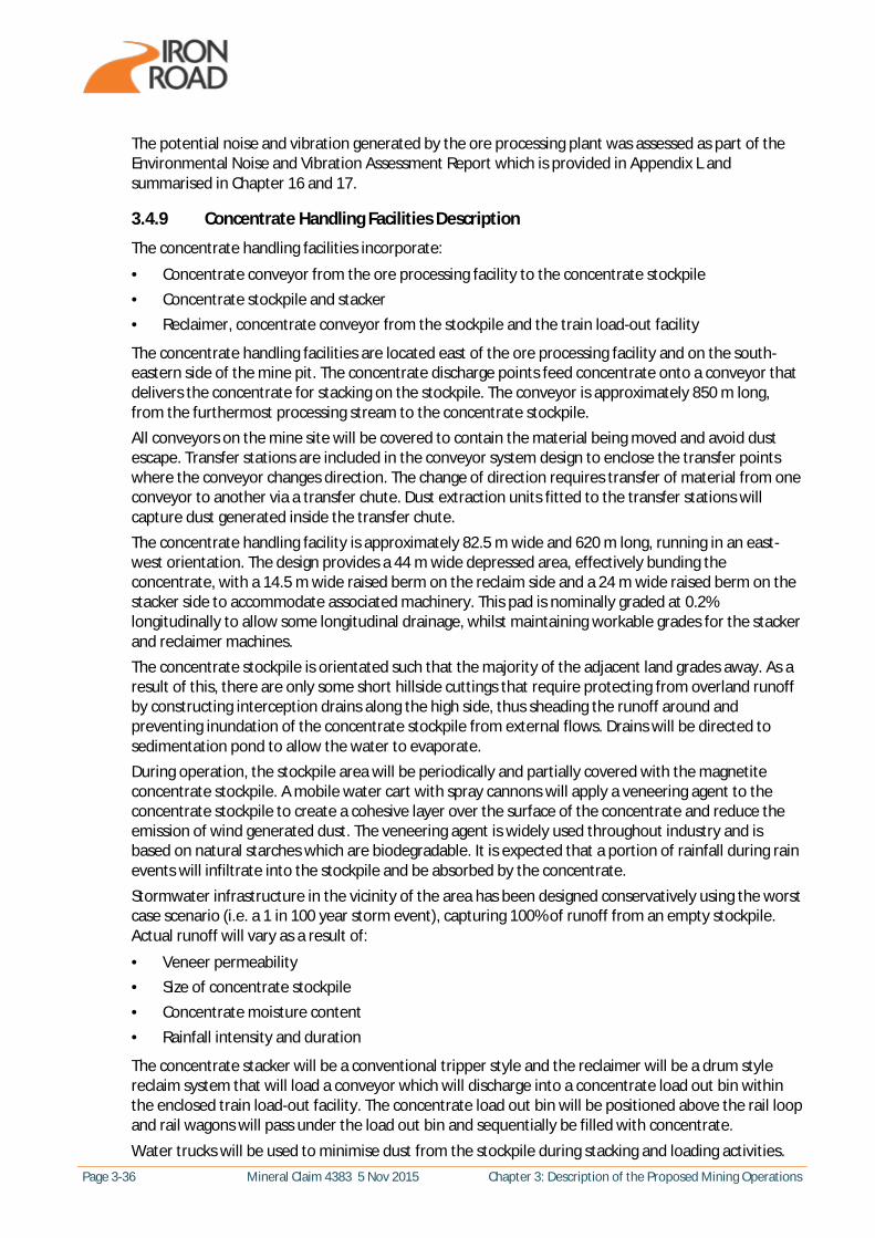
Page 3-36 Mineral Claim 4383 5 Nov 2015 Chapter 3: Description of the Proposed Mining Operations
The potential noise and vibration generated by the ore processing plant was assessed as part of the Environmental Noise and Vibration Assessment Report which is provided in Appendix L and summarised in Chapter 16 and 17.
3.4.9 Concentrate Handling Facilities Description
The concentrate handling facilities incorporate:
· Concentrate conveyor from the ore processing facility to the concentrate stockpile · Concentrate stockpile and stacker · Reclaimer, concentrate conveyor from the stockpile and the train load-out facility
The concentrate handling facilities are located east of the ore processing facility and on the south-eastern side of the mine pit. The concentrate discharge points feed concentrate onto a conveyor that delivers the concentrate for stacking on the stockpile. The conveyor is approximately 850 m long, from the furthermost processing stream to the concentrate stockpile. All conveyors on the mine site will be covered to contain the material being moved and avoid dust escape. Transfer stations are included in the conveyor system design to enclose the transfer points where the conveyor changes direction. The change of direction requires transfer of material from one conveyor to another via a transfer chute. Dust extraction units fitted to the transfer stations will capture dust generated inside the transfer chute. The concentrate handling facility is approximately 82.5 m wide and 620 m long, running in an east-west orientation. The design provides a 44 m wide depressed area, effectively bunding the concentrate, with a 14.5 m wide raised berm on the reclaim side and a 24 m wide raised berm on the stacker side to accommodate associated machinery. This pad is nominally graded at 0.2% longitudinally to allow some longitudinal drainage, whilst maintaining workable grades for the stacker and reclaimer machines. The concentrate stockpile is orientated such that the majority of the adjacent land grades away. As a result of this, there are only some short hillside cuttings that require protecting from overland runoff by constructing interception drains along the high side, thus sheading the runoff around and preventing inundation of the concentrate stockpile from external flows. Drains will be directed to sedimentation pond to allow the water to evaporate. During operation, the stockpile area will be periodically and partially covered with the magnetite concentrate stockpile. A mobile water cart with spray cannons will apply a veneering agent to the concentrate stockpile to create a cohesive layer over the surface of the concentrate and reduce the emission of wind generated dust. The veneering agent is widely used throughout industry and is based on natural starches which are biodegradable. It is expected that a portion of rainfall during rain events will infiltrate into the stockpile and be absorbed by the concentrate. Stormwater infrastructure in the vicinity of the area has been designed conservatively using the worst case scenario (i.e. a 1 in 100 year storm event), capturing 100% of runoff from an empty stockpile. Actual runoff will vary as a result of:
· Veneer permeability · Size of concentrate stockpile · Concentrate moisture content · Rainfall intensity and duration
The concentrate stacker will be a conventional tripper style and the reclaimer will be a drum style reclaim system that will load a conveyor which will discharge into a concentrate load out bin within the enclosed train load-out facility. The concentrate load out bin will be positioned above the rail loop and rail wagons will pass under the load out bin and sequentially be filled with concentrate.
Water trucks will be used to minimise dust from the stockpile during stacking and loading activities.

Chapter 3: Description of the Proposed Mining Operations Mineral Claim 4383 5 Nov 2015 Page 3-37
3.4.10 Mine Dewatering
To achieve safe mining conditions, it will be necessary to actively manage rainfall run-off and groundwater inflow to the pit. In-pit pumping infrastructure is designed to manage large volumes of rainfall run-off during peak rainfall events (RPS, 2015). Stormwater following peak rainfall events will be delivered to the process water pond and used in the plant (with temporary reduced demand on the borefield water supply). In-pit pumping infrastructure will be operated at reduced duty to manage groundwater seepage and the saline water subsequently used for dust suppression. The dewatering strategy is just-in-time dewatering, designed to maximise water content in the rock to control dust, whilst providing safe working conditions in the pit. Ex-pit abstraction wells will not be used unless required. A numerical groundwater flow model has been used to estimate the volumes of groundwater to be abstracted. The model output provides an upper estimate of dewatering rates, implementing both ex-pit bores and in –pit pumping. The predicted ex-pit (dewatering well) and in-pit (sump pump) abstraction volumes are illustrated in Figure 3-15. The groundwater model provides no allowance for evaporation of groundwater seepage which is expected to be a significant component of the pit water balance and no allowance for removal of water contained in excavated ore and waste rock. The volume of water removed by excavation is approximately 3.6 Gl/year. Pan evaporation in summer peaks at 6.6 mm per day in January and decreases to 1.6 mm per day in June (Kyancutta BOM station). For a combined pit area of 8.9 km2 this equates to potential evaporation of 14 to 59 ML/day. In-pit evaporation will be some lesser value controlled by: seepage distribution (concentrated piping vs diffuse seepage), pit configuration, seepage drainage, surface roughness and water storage. The model predicts in-pit seepage rates ranging from 3 to 17 ML/day. Elimination of ex-pit bore pumping and the removal of a very significant proportion of seepage by evaporation and rock excavation is expected to reduce the actual volume of water that reports to the pit sumps to zero in mid-summer, to up to around 10 ML/day in winter. The varying water available for dust suppression (seasonal variation due to evaporation and life of mine variation due to mine pit progression) will be managed by; firstly additional pumping from ex-pit bores (essentially intersecting groundwater seepage before it is lost to evaporation), secondly by diversion of RO brine from the process plant and thirdly by additional pumping from the mine water supply borefield. Excess water, particularly following peak rainfall events, will be managed by addition to the process water pond with reduced borefield demand.
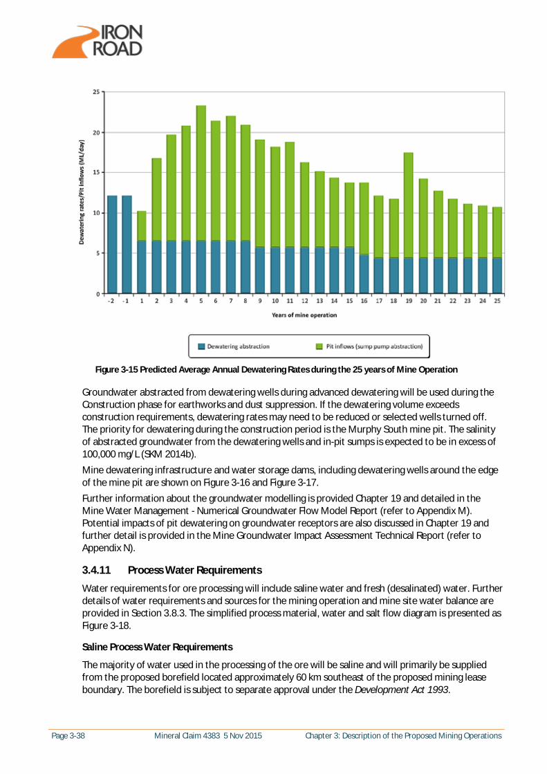
Page 3-38 Mineral Claim 4383 5 Nov 2015 Chapter 3: Description of the Proposed Mining Operations
Figure 3-15 Predicted Average Annual Dewatering Rates during the 25 years of Mine Operation
Groundwater abstracted from dewatering wells during advanced dewatering will be used during the Construction phase for earthworks and dust suppression. If the dewatering volume exceeds construction requirements, dewatering rates may need to be reduced or selected wells turned off. The priority for dewatering during the construction period is the Murphy South mine pit. The salinity of abstracted groundwater from the dewatering wells and in-pit sumps is expected to be in excess of 100,000 mg/L (SKM 2014b). Mine dewatering infrastructure and water storage dams, including dewatering wells around the edge of the mine pit are shown on Figure 3-16 and Figure 3-17. Further information about the groundwater modelling is provided Chapter 19 and detailed in the Mine Water Management - Numerical Groundwater Flow Model Report (refer to Appendix M). Potential impacts of pit dewatering on groundwater receptors are also discussed in Chapter 19 and further detail is provided in the Mine Groundwater Impact Assessment Technical Report (refer to Appendix N).
3.4.11 Process Water Requirements
Water requirements for ore processing will include saline water and fresh (desalinated) water. Further details of water requirements and sources for the mining operation and mine site water balance are provided in Section 3.8.3. The simplified process material, water and salt flow diagram is presented as Figure 3-18.
Saline Process Water Requirements
The majority of water used in the processing of the ore will be saline and will primarily be supplied from the proposed borefield located approximately 60 km southeast of the proposed mining lease boundary. The borefield is subject to separate approval under the Development Act 1993.

Chapter 3: Description of the Proposed Mining Operations Mineral Claim 4383 5 Nov 2015 Page 3-39
Approximately 12 GL/year of saline groundwater from the borefield will be required to provide saline process water requirements. Saline groundwater from the borefield will be piped from the borefield along the proposed infrastructure corridor and discharged into the groundwater storage dam. The groundwater storage dam will have a capacity of 400 ML and will store approximately 10 days’ supply of saline process water requirements. The saline water demand is primarily controlled by the volume of water lost to tailings. Sensitivity analysis of dewatered tailings moisture content indicates that the moisture content of tailing could vary from 4.2% to 9.3% with a base case estimate of 6.8% (GWS, 2015). The concomitant water demand from the borefield ranges from 9 to 15 GL/yr with a base case estimate of 12 Gl/yr. Minor variable amounts of saline process water will also be sourced from mine run-off following rainfall events (average annual volume is 0.4 Gl, RPS,2015), water within the ore and rain falling directly on the groundwater storage and process water dams. Additional captured rainfall run-off in wet years will offset pumping from the borefield.
Fresh (Desalinated) Process Water Requirements
A reverse osmosis (RO) plant will be located adjacent to the groundwater storage dam to produce desalinated water to be used for rinsing the concentrate to remove salts. The desalinated water will also be treated for potable use. Brine wastewater from the RO process will be used for dust suppression on the active (un-rehabilitated) part of the IWL. Fresh desalinated water will be used for dust suppression and plant establishment on the progressively rehabilitated part of the IWL. Approximately 1,963 ML/year of fresh (desalinated) water will be required for processing of ore, with an additional 38 ML/year of potable water required for use in the process plant.
Figure 3-16 Locations of Water Storage Dams

Page 3-40 Mineral Claim 4383 5 Nov 2015 Chapter 3: Description of the Proposed Mining Operations
Figure 3-17 Proposed Dewatering Well Locations
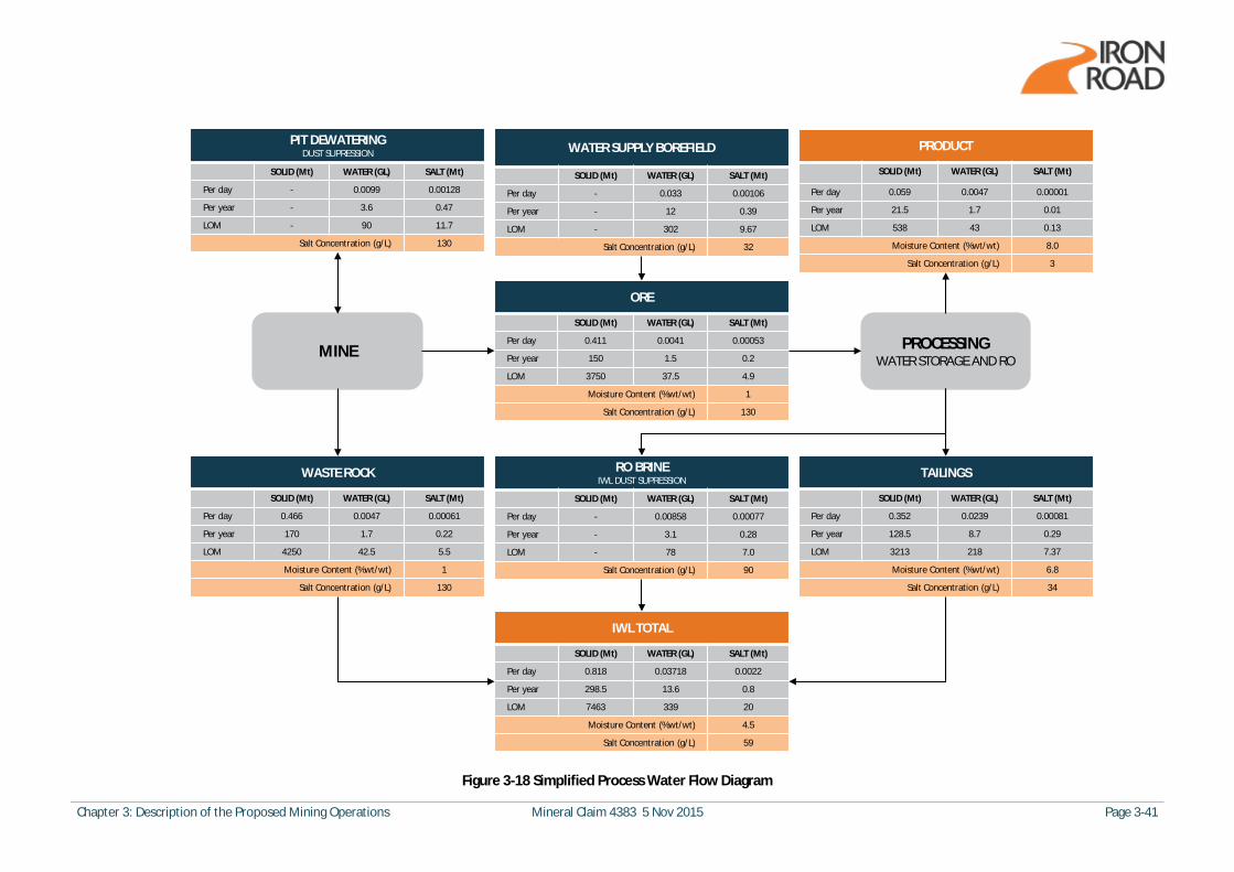
Chapter 3: Description of the Proposed Mining Operations Mineral Claim 4383 5 Nov 2015 Page 3-41
PIT DEWATERINGDUST SUPRESSION
SOLID (Mt) WATER (GL) SALT (Mt)
Per day - 0.0099 0.00128
Per year - 3.6 0.47
LOM - 90 11.7
Salt Concentration (g/L) 130
MINE
WASTE ROCK
SOLID (Mt) WATER (GL) SALT (Mt)
Per day 0.466 0.0047 0.00061
Per year 170 1.7 0.22
LOM 4250 42.5 5.5
Moisture Content (%wt/wt) 1
Salt Concentration (g/L) 130
WATER SUPPLY BOREFIELD
SOLID (Mt) WATER (GL) SALT (Mt)
Per day - 0.033 0.00106
Per year - 12 0.39
LOM - 302 9.67
Salt Concentration (g/L) 32
ORE
SOLID (Mt) WATER (GL) SALT (Mt)
Per day 0.411 0.0041 0.00053
Per year 150 1.5 0.2
LOM 3750 37.5 4.9
Moisture Content (%wt/wt) 1
Salt Concentration (g/L) 130
IWL TOTAL
SOLID (Mt) WATER (GL) SALT (Mt)
Per day 0.818 0.03718 0.0022
Per year 298.5 13.6 0.8
LOM 7463 339 20
Moisture Content (%wt/wt) 4.5
Salt Concentration (g/L) 59
PROCESSINGWATER STORAGE AND RO
TAILINGS
SOLID (Mt) WATER (GL) SALT (Mt)
Per day 0.352 0.0239 0.00081
Per year 128.5 8.7 0.29
LOM 3213 218 7.37
Moisture Content (%wt/wt) 6.8
Salt Concentration (g/L) 34
RO BRINEIWL DUST SUPRESSION
SOLID (Mt) WATER (GL) SALT (Mt)
Per day - 0.00858 0.00077
Per year - 3.1 0.28
LOM - 78 7.0
Salt Concentration (g/L) 90
PRODUCT
SOLID (Mt) WATER (GL) SALT (Mt)
Per day 0.059 0.0047 0.00001
Per year 21.5 1.7 0.01
LOM 538 43 0.13
Moisture Content (%wt/wt) 8.0
Salt Concentration (g/L) 3
Figure 3-18 Simplified Process Water Flow Diagram
Page 3-42 Mineral Claim 4383 5 Nov 2015 Chapter 3: Description of the Proposed Mining Operations
3.5 Waste
3.5.1 Processing Wastes
Saline water and tailings will be the dominant waste outputs from the ore processing facility. Ore processing will be undertaken using saline water which substantially reduces the project demand for fresh water. Freshwater is used only during the final rinse of the product. Water is recovered from the tailings by dewatering to be recycled; however waste water is produced in two streams; entrained water within the tailings and brine from the reverse osmosis (RO) plant. The filtered tailings, with the consistency of damp sand (an approximate moisture content of 6.8%), will consist mainly of the non-magnetic components of the ore, which are predominately silicate and alumina minerals. Approximately 130 Mtpa of tailings will be produced with 60% coarse tailings (130 µm - 6 mm) and 40% fine tailings (<130 µm). Tailings will be disposed of to the IWL as detailed in Section 3.5.2. Brine from the RO plant will be used for dust suppression on the active (non-rehabilitated) part of the IWL. Salt comprises a proportion of the waste generated from the process. The salt balance is presented as part of the material, salt and water balance (Figure 3-18). Salt is imported to the site from the water supply borefield in the form of saline groundwater and salt is mobilised from the pit contained within the moisture on the ore and waste rock. Mine pit dewatering also mobilises salt however this component is recycled within the pit and haul roads through dust suppression. The total salt throughput is approximately 0.8 Mtpa. The salt is ultimately discharged to the IWL within the moisture retained by the tailings and the waste rock and through application of RO waste brine to the IWL for dust suppression. The total average salt content of the IWL is approximately 0.3% and accumulates to a total mass over the life of mine of 20 Mt. The salt will remain stored within the IWL. Seepage of emplaced water is not predicted due to the water content of the placed material being less than the specific retention (Groundwater Science, 2015). Minor rainfall infiltration and seepage from the IWL is predicted (Refer Chapter 19 Groundwater), however this will report to the already saline groundwater table at low rates that do not cause the water table to rise. Over very long time frames (100s of years) rainfall infiltration to the IWL will report to the saline mine pit lake.
3.5.2 Integrated Waste Landform
The IWL design concept is presented in detail in Appendix S (with supporting technical reports within). Waste rock and tailings (both fine and coarse) are the only waste products from the mining operation and both are proposed to be stored within a single IWL with material to be delivered via three conveyor spreader systems operating concurrently. Combining the waste material streams in the IWL provides a number of advantages over a regular truck and shovel and tailings storage facility disposal designs, including:
· A highly managed rock storage approach, enabling placement of material streams in locations which maximise the ability to meet design objectives.
· A reduced overall landform footprint as voids within waste rock are filled with finer tailings and the need for separate waste rock storage and tailings storage facilities is removed.
· Co-disposal of an integrated waste stream enables potentially acid forming materials (PAF) to co-mingle with materials which have an acid neutralising capacity (ANC).
· A greater ability to meet local stakeholder objectives in terms of visual amenity and minimised footprint.
Chapter 3: Description of the Proposed Mining Operations Mineral Claim 4383 5 Nov 2015 Page 3-43
The concept landform design is consistent with work in progress and completed for waste rock and IWL designs in Australia over the last 20 years. Concave and linear slopes, often rock armoured and of varied configuration, exist at mine sites such as Wiluna Gold and Mt McClure. Two IWLs containing tailings are found at the Challenger Mine and at Sunrise Dam, which has a 30 m high concave armoured slope. Large landforms with stable water harvesting berms can be found at Granny Smith, Leinster Nickel and Kalgoorlie Consolidated Gold Mines. At the Jundee mine, the W10 landform, with a 30 m vertical height armoured concave slope, has 0.15 m of topsoil ripped into the armoured surface and is somewhat analogous to the landform design presented here, although it is important to note that all have unique features which make direct comparisons difficult.
Size and Location of the IWL Storage Facility
The IWL will be located within the southern portion of the proposed mining lease to the south of the pit, as indicated on Figure 3-1. The IWL will have a footprint of approximately 1,970 ha at mine completion with a buffer between the Life of Mine (LOM) IWL footprint and the proposed mining lease boundary of 50 m minimum. The IWL will have an approximate height of 135 to 150 m above natural ground level, depending on natural topographic variations of the existing ground and at a course level, it would represent a concave landform analogous with natural (non-granite outcrop) landforms in the region. Further details regarding the size and location of the IWL are provided in Appendix S.
Estimated Volumes to be Stored and Material Composition
Mine waste material includes oxide bulk waste (overburden) and fresh bulk waste rock from both the Murphy South and Boo Loo pits. The overburden includes up to 30 to 40 m of oxidised gneissic material above the ‘barren gneiss’ fresh waste rock and up to 70 m of overburden cover above the ‘magnetite gneiss’ orebody. A fine and a coarse tailings material will be generated by mine processing of the magnetite gneiss orebody. The waste material composition is described in detail within Appendix S, but in summary will compose of:
· Waste rock material (barren and fresh gneiss) crushed to 160 mm and below · Fine tailings: 0% gravel, 43% fines, 31% fine sand, 26% medium sand · Coarse tailings: 24% gravel, 1% fines, 1% fine sand, 16% medium sand, 58% coarse sand
The combined volume of waste rock and tailings materials for the LOM is approximately 3,370 Mm3. 1,800 Mm3 will be stored in the IWL, with the remaining volume stored in the Zones A and B as shown in Figure 3-19. Detailed mine planning and material block modelling will refine material balances and the final placement of materials will be optimised. The LOM volumes includes 1,982 Mm3 (approximately 60 %) of waste rock (including oxide and fresh rock) and 1,388 Mm3 (approximately 40 %) of tailings material (coarse and fine fractions). Table 3-14 summarises the waste material volumes. A mine waste material inventory and storage volume comparison is described in further detail in Appendix S.

Page 3-44 Mineral Claim 4383 5 Nov 2015 Chapter 3: Description of the Proposed Mining Operations
Figure 3-19 Provisional Additional Waste Storage Locations

Chapter 3: Description of the Proposed Mining Operations Mineral Claim 4383 5 Nov 2015 Page 3-45
Table 3-14 Preliminary Mine Waste Materials Inventory for the CEIP (MWH 2015 in Appendix S)
Mine Waste Material Type Tonnage Volume 1
Annualised Average (Mtpa)
LOM Tonnes (Mt)
Annualised Average (Mm3pa)
LOM Volume (Mm3)
Waste rock Total (oxide and fresh rock) 170 4,360 77 1,982
Tailings Combined coarse and fine fractions 130 3,053 59 1,388
TOTAL 300 2 7,413 136 2 3,370
1. A consolidated stress bulk density of 2.2 t/m3 estimated for the combined tailings/waste rock upon deposition within the IWL (information from Iron Road).
2. The annual production of waste rock and tailings to be combined within the IWL. An assessment of the geochemistry of the waste materials indicates the following:
· Confirmed low total sulphur content with approximately 2% of total waste material (oxide, fresh rock and tailings) considered potentially acid forming.
· Approximately 10% of the oxide material to be encountered is classified as potentially acid forming (PAF), with the majority (estimated 90% by volume) of this PAF material classified as having low to very low acid generating potential (<0.5% sulphur).
· PAF material with total sulphur exceeding 1% comprises approximately 0.5% of the entire overburden material. This material is considered to be a low net acid production potential.
· The tailings component has a high Acid Neutralisation Capacity (ANC) ratio >2 (average ratio of 17) and high ANC (average of 15.6 kg H2SO4/t).
· Indicated negligible or low metal and elemental concentrations with the exception of manganese (average of 1140 mg/kg compared to an ecological investigation level (EIL) of 500 mg/kg and average crustal abundance of 950 mg/kg for manganese).
Further details around the geochemistry and management planning for the IWL are provided in the CEIP Oxide Zone Mine Waste Geochemistry Review incorporating an Acid Management Drainage Management Plan (within Appendix S).
Method of Material Placement
An advantageous feature of the IWL is the construction method which employs three mobile stacker conveyors concurrently placing material in a roughly ‘semi-circular’ arrangement. Material placement onto the IWL involves a central loading area where materials are placed on to the conveyor systems, with each conveyor system placing approximately 45 m of material (with some variation on the lower lift due to variability of the Nominal Ground Level (NGL)). The method of material placement creates a number of opportunities for the construction process, including:
· The capability to strategically design the mix of materials for different areas of the landform, such as across the flat upper surfaces and on the side slopes. This would be done by selecting specific material trains to feed the conveyors from the central loading area.
· The opportunity to use a high proportion of waste rock material (to 160 mm in diameter) in the outer layer of the surface to minimise the erosion risks.
· The opportunity to integrate topsoil and subsoil into the material mix for the outer cover layer to facilitate effective landform rehabilitation (discussed further below).
· The potential for creating variability in the top surface through variation of the final back stacking placement.

Page 3-46 Mineral Claim 4383 5 Nov 2015 Chapter 3: Description of the Proposed Mining Operations
The landform design involves the three stackers (an example is illustrated in Plate 3-4), each building a 45 m lift in two stacks; a front or forward stack of 30 m and a back stack of 15 m. This construction approach limits the future need for dozing or double handling. The design for the IWL is considered extremely conservative and includes the following approach to material placement:
· The front stack of each conveyor is designed as a concave outer slope, with typical heights of 30 m, but potentially slightly higher due to the back slope of benches (i.e. up to 35 m for the second concave slope). The lowest bench is also higher in places (up to 50 m) due to the variation of the natural ground level. The concave slopes range from 18 degrees (1 vertical : 3 horizontal) to 11.3 degrees (1 vertical : 5 horizontal) for the 30 m high lifts, but flatten further for the longer lower slopes to generate an overall concave outer slope, with the slope reducing to 9.46 degrees (1 vertical : 6 horizontal).
· The benches have been made progressively wider moving downslope, to generate an overall concave outer slope, with each bench designed to accommodate the sediment loading and runoff for the design event for the full upslope catchment measured from each bench to the crest of the IWL and not just the inter-bench catchment. The benches vary in width from 20 m on the upper bench, to 100 m for the lowest and widest bench.
· For the back stack of each stacker, the slopes are linear with typical heights of 15 m, again increasing slightly in height due to the back slope of benches. The slope angle for the back stacks will be 18 degrees (1 vertical : 3 horizontal).
· In addition to a crest bund on the upper edge of the IWL, each of the upper three benches will have crest bunds, typically 1.5 m in height, to further limit the risk of overspill from the bench.
Based on the above design criteria, representations of the proposed outer slope profile and the overall conceptual landform shape are presented in Figure 3-20 and Figure 3-21 respectively (with further details in Appendix S).
Plate 3-4 Example of an IWL Spreader
Chapter 3: Description of the Proposed Mining Operations Mineral Claim 4383 5 Nov 2015 Page 3-47
Benefits of material placement via use of three concurrent stackers are discussed in detail in Appendix S and include:
· Improved safety with increased landform stability during construction and at closure and minimal truck use along landform wall faces.
· Improved efficiency during construction with reduced diesel requirements (and subsequent reduction in greenhouse gas emissions).
· Reduced noise impacts during construction. · Reduced wheel-generated dust emissions and the ability to place ‘rock mulch’ over final surfaces
to stability and suppress dust until rehabilitation. · Ability to undertake progressive rehabilitation as final landform height is progressively reached.
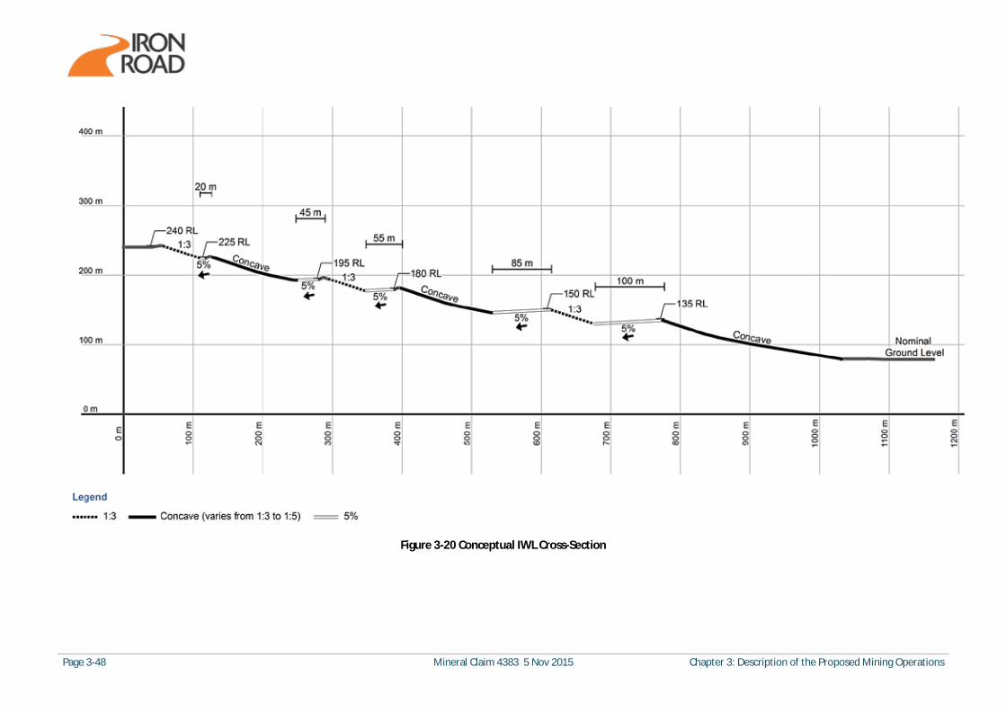
Page 3-48 Mineral Claim 4383 5 Nov 2015 Chapter 3: Description of the Proposed Mining Operations
Figure 3-20 Conceptual IWL Cross-Section

Chapter 3: Description of the Proposed Mining Operations Mineral Claim 4383 5 Nov 2015 Page 3-49
Figure 3-21 Conceptual Design of the IWL (view from south-east to north-west)
Proposed Landform Cover Profile
In addition to the mine waste materials discussed above, topsoil and subsoil materials will be available from the mine pit pre-strip, beneath other site infrastructure and from beneath the IWL if required. This material represents an important resource for use in the final landform cover to facilitate landform rehabilitation and future use. The proposed concept design for the landform cover is presented graphically in Figure 3-22 and consists of:
· 0.15 m of topsoil over 3 m of subsoil / waste rock mix (25% subsoil / 75% waste rock) over 1.5 – 2 m of straight waste rock (as a capillary break) on the flat upper surface.
· 0.15 m of topsoil over 2 m of subsoil / waste rock mix (25% subsoil / 75% waste rock) over 1.5 – 2 m of straight waste rock (as a capillary break) on the batter slopes.
The 0.15 m of topsoil in the cover profile has been applied as it represents a practical estimate for consideration of soil volumes and material balances, where the spreading of material in large volumes by heavy machinery is likely to vary between 0.1 and 0.2 m depth. A minimum depth of 0.1 m of topsoil is considered necessary for successful plant germination and application of topsoil at depths greater than 0.2 m have been observed to present surface stability and erosion issues when applied in reconstructed profiles on landform slopes. In addition, viability of contained seedbank and germination success can also reduce at depths greater than 0.2 m. Based on the proposed cover profile and concept IWL design, estimates of required topsoil and subsoil volumes were undertaken and compared with volumes available. Estimates of topsoil and sub-soil volumes available were calculated from soil bores undertaken across the site (see Appendix S for further details) which indicate availability of a combined total of approximately 50.1 Mm3 (10.2 and 39.8 Mm3 of topsoil and subsoil respectively). The proposed cover profile for the concept IWL requires 2.95 and 24.5 Mm3 of topsoil and subsoil respectively; a total of 27.45 Mm3. The comparison is provided in Table 3-15, which at a high level demonstrates sufficient topsoil and subsoil for the proposed cover profile.
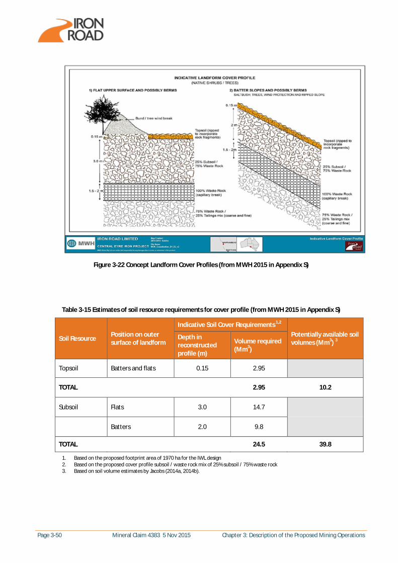
Page 3-50 Mineral Claim 4383 5 Nov 2015 Chapter 3: Description of the Proposed Mining Operations
Figure 3-22 Concept Landform Cover Profiles (from MWH 2015 in Appendix S)
Table 3-15 Estimates of soil resource requirements for cover profile (from MWH 2015 in Appendix S)
Soil Resource Position on outer surface of landform
Indicative Soil Cover Requirements 1,2
Potentially available soil volumes (Mm3) 3
Depth in reconstructed profile (m)
Volume required (Mm3)
Topsoil Batters and flats 0.15 2.95
TOTAL 2.95 10.2
Subsoil Flats 3.0 14.7
Batters 2.0 9.8
TOTAL 24.5 39.8
1. Based on the proposed footprint area of 1970 ha for the IWL design 2. Based on the proposed cover profile subsoil / waste rock mix of 25% subsoil / 75% waste rock 3. Based on soil volume estimates by Jacobs (2014a, 2014b).
Chapter 3: Description of the Proposed Mining Operations Mineral Claim 4383 5 Nov 2015 Page 3-51
Material Balance
A further consideration for material availability relates to the timing of material availability and the temporary storage of required material which cannot be immediately used. A detailed ‘block model’ for all material movement over the life of the mine will be undertaken during detailed design. A high level material balance was undertaken which indicates that topsoil material (both native vegetation seedbank topsoil and agricultural topsoil) will be required to be stockpiled at the topsoil temporary storage area (refer to Section 3.4.6 and Figure 3-1) for use in progressive rehabilitation as the IWL develops. A total of 2.95 Mm3 of topsoil is required for the IWL cover profile design, as indicated in Table 3-15. This will include both native vegetation topsoil and agricultural topsoil. A native topsoil stockpile will be generated during the construction phase of the project to collect, store and protect the valuable native topsoil material for progressive use throughout the production phase. All of the native vegetation topsoil beneath the project footprint (mine pit, IWL and infrastructure) is estimated to be 1.32 Mm3, which requires approximately 663,252 m2 of storage area if stored at 2 m height (approximately 814 m x 814 m). This represents the ‘peak’ or worst case stockpile size (indicated on Figure 3-1) assuming all material is collected during the construction phase and stored, from where it would be progressively drawn on for use in the IWL cover profile without additional material being added. A more realistic scenario is that native vegetation topsoil will be stockpiled progressively as surface material is pre-stripped or just prior to it being covered by the IWL, with progressive drawdown of the stockpile for use on the IWL as it develops. Material balance modelling indicates that if 30 % of the mine pit is pre-stripped during the construction phase as planned and resulting native vegetation topsoil is stockpiled with a drawdown of 48,890 m3 per year (representing the total requirement spread between two construction years and 25 production years), a maximum native vegetation topsoil stockpile size of 289,369 m2 (at 2 m height) is required (approximately 538 m by 538 m accounting for batters). An agricultural topsoil stockpile will be generated initially as topsoil is stripped beneath site infrastructure (in year 1 of construction) then progressively added to as topsoil is pre-stripped from the mine pit, indicatively with 50% of the pit stripped by year 5 of production. A total of 3.7 Mm3 of agricultural topsoil is available from beneath site infrastructure and from the mine pit pre-strip, with only 2.07 Mm3 required in the cover profile of the IWL design. Stockpiling all of the available material (with no drawdown) results in a maximum (worst case) stockpile size of 171,140 m2 at 10 m height. A more realistic scenario is that this material will be progressively used in the landform cover (as per the native vegetation seedbank topsoil) as the landform establishes. Material balance modelling indicates that if that if 30 % of the mine pit is pre-stripped during the construction phase as planned and resulting agricultural topsoil is stockpiled with a drawdown of 60,370 m3 per year (representing the total requirement spread between two construction years and 25 production years), a maximum agricultural topsoil stockpile size of 37,596 m2 (at 2 m height) is required (approximately 194 m by 194 m accounting for batters). 24.5 Mm3 of sub soils are required for the IWL cover profile, as indicated in Table 3-15. A stockpile of subsoils will be generated as pre-stripped subsoils will be generated at a rate faster than subsoils are required in the IWL cover profile during the construction phase and first 2 years of production. Subsoils from the preliminary mine pit pre-strip (10 % of pit area per year during construction and for the first 2 years of production) equate to approximately 2.68 Mm3 per year compared with approximately 0.9 Mm3 required in the IWL cover per year. 2.3 Mm3 of subsoils are used in the IWL ramp generation in year 1 of construction leaving 0.38 Mm3 to be stockpiled in the first year. The excess subsoils are subsequently stockpiled which results in an increasing stockpile size until year 3 of production when the pre-strip rate drops to 2-3 % of the pit area. From this point forward, the stockpile size decreases over the life of the mine. The maximum subsoil stockpile size is 7.47 Mm3, approximately 764,390 m2 at 10 m height accounting for batters.

Page 3-52 Mineral Claim 4383 5 Nov 2015 Chapter 3: Description of the Proposed Mining Operations
Method of Stabilisation and Erosion Control
As indicated above, the concept IWL includes wide lower benches with concave slopes and is considered to be an extremely conservative design. The benefits of the progressively wider benches for the lower sections of the landform are as follows:
· There is a provision to prevent progressive failure down the slope, since each bench is designed to contain the total sediment and runoff load from the upslope catchment.
· The lower bench designs are extremely conservative and (for the 200 year modelling analysis) no overtopping from the upper benches is predicted.
· The wider benches provide significant attenuation of any future overspills. Peak flow rates of any overspill will be significantly reduced, which will further reduce the risk of erosion in the long term.
Landform modelling of the concept design predicts exceptional erosion outcomes. Siberia modelling (for a 200 year design, assessing water management based on the 1% Annual Exceedance Probability (AEP) storm event, which is equivalent to the 1:100 year storm event) indicates erosion rates of 5-10 t/ha/yr without inclusion of bunding on each bench or vegetative cover for a surface cover material comprising 50% rock and 50% topsoil/subsoil (a conservative, less stable material ratio than that proposed). Inclusion of benches in the modelling reduces the erosion rate to approximately 5 t/ha/yr and a crest bund is planned to be placed on the upper surface crest. All the berm surfaces will be shaped to ensure water is contained and does not flow along the berm and ponding of water against the crest bund will also be minimised by the back sloping grade of the upper berm surface, limiting the risk of piping. Increasing the proportion of rock in the outer cover material to the proposed landform concept design of 75% (from the 50% discussed above) is predicted by the modelling to reduce the overall erosion rates by around 30%. Detailed landform modelling results are presented in Appendix S to demonstrate how this design was reached. A critical aspect of the design relates to the hydraulic properties of the proposed soil/waste rock cover profile and the capacity of the cover profile to control rainfall infiltration through ‘store and release’, thereby minimising through-drainage into the landform. To protect the growth cover from capillary rise of salts, the design includes the application of a 1.5 to 2 m capillary break of straight rock beneath the cover profile. The performance of the soil cover will result from a combination of both its physical properties and its overall capacity to support plant growth. The physical properties will directly influence rainfall infiltration and water storage in the profile and the store and release properties will enable plant roots to source water. Productive vegetation cover will drive further landform stability. Successful revegetation of the slopes is also expected to improve surface stability. The IWL concept design includes a surface cover which incorporates topsoil and subsoil into a stabilising rock matrix. This medium is expected to allow establishment of native plant species which will act to further stabilise the slopes and soften the visual impacts of the landform. Revegetation and rehabilitation trials will commence as soon as the final landform height is reached, to determine the optimal mix of waste rock and soils and progressive rehabilitation will reduce the area of land exposed to surface water and wind erosion.

Chapter 3: Description of the Proposed Mining Operations Mineral Claim 4383 5 Nov 2015 Page 3-53
Landform Slope Stability
Long-term landform stability is discussed above, with reference to design features and landform modelling. The geotechnical stability of the landform was also assessed to determine the factors of safety in relation to use of mobile conveyor and stacker equipment on the landform during construction. Geotechnical modelling indicates an anticipated factor of safety against bearing capacity failure beneath the tracks of the stacker machine for an applied pressure of 120 kPa is 3.0 with estimated settlement of 25 to 40 mm. The anticipated factor of safety is considered more than adequate for the transient nature of the load and the estimated settlements are within the tolerances of the spreader machine (details provided in the IWL Geotechnical Stability Technical Note within Appendix S).
Plate 3-5 Example of Mobile Spreader Placing Material at the Toe of Slope
3.5.3 Industrial and Commerical Wastes
Solid Waste
A breakdown of the various waste streams likely to be generated at the mine site and the preferred location for disposal of the waste is provided in Table 3-16. This indicative list of waste streams has been informed by information on waste generated by the mining industry in the Waste Account of Australia (Australian Bureau of Statistics 2013) as well as project-specific consideration of waste sources.

Page 3-54 Mineral Claim 4383 5 Nov 2015 Chapter 3: Description of the Proposed Mining Operations
Table 3-16 Indicative Waste Streams at the Proposed Mine Site
Waste Stream Preferred Method of Disposal
Paper and cardboard Offsite recycling facility
Recyclable food containers and packaging including plastic, bottles, cans, metal and glass Offsite recycling facility
Scrap metal Offsite recycling facility
Tyres and other rubber Offsite recycling facility
Electrical and electronic Offsite recycling facility
Solid hazardous waste Licenced facility (offsite)
Waste oil Offsite recycling facility
Masonry Onsite landfill
General waste – inseparable Onsite landfill or Wudinna landfill
Plastics Wudinna landfill
Organics and putrescible Wudinna landfill
Leather and textiles Wudinna landfill
Timber and wood Wudinna landfill
Further information including estimated waste quantities and benchmarking against comparable mine sites in South Australia and regional landfill capacities is provided in Chapter 14.
Sewerage Reticulation and Treatment
Sewage generated within the proposed mining lease will be treated on site via a package wastewater treatment plant (WWTP) with treated water utilised for the watering and maintenance of vegetation and/or landscaping within the mine site. The sewer reticulation system will comprise gravity pipes connected to each facility serviced by the sewerage treatment system. Due to the topography of the site and distance between each service facility, a number of small pump stations are required to transfer the waste via a pressure reticulation system to the centralised WWTP for treatment and disposal. The treatment system will comprise a spray irrigation sprinkler and pipework system along for disposal via infiltration and evaporation. The proposed location of the WWTP is to the east of the ore processing facility, with a minimum 150 m clear zone either side to surrounding infrastructure; however the final site is yet to be determined and has not be identified on the mine site layout. The design flows for the WWTP are based on the staffing numbers and estimated daily flow per person. This produces a design inflow of 50,600 L/day. The spray irrigation rate adopted for sizing the irrigation area is based on an application rate of 4.5 L/m2/day. This results in an area of approximately 11,200 m2 or an approximate footprint of 130 m by 115 m including allowance for the WWTP, hardstand and access track. The treatment plant facility, including spray irrigation network will be fenced.
Chapter 3: Description of the Proposed Mining Operations Mineral Claim 4383 5 Nov 2015 Page 3-55
3.6 Supporting Surface Infrastructure A number of ancillary facilities will be located within the proposed mining lease to support mine operations. These include:
· New and upgraded internal and external access roads · Accommodation and administration buildings · Emergency services · Public utilities · Landscaping · Fuel and chemical storage · Site security infrastructure · Stormwater management and drainage infrastructure
These facilities are described briefly in the sections below.
3.6.1 Site Access
The following section describes access arrangements to the mine site, including the existing public roads proposed to be used for access, proposed road upgrades, internal access arrangements and module access. In addition to alterations to the local road network, Wudinna airport is proposed to be upgraded to accommodate commercial flight movements required for the fly-in/fly-out construction workforce. The upgrade to Wudinna airport is being pursued by Wudinna DC as part of a separate approvals process.
Access Roads
Prior to project implementation, management agreements would be entered into with Wudinna DC for a range of items, including road maintenance. A regular independent road condition and use audit would be undertaken to ensure fair and equitable maintenance costs of roads are allocated to Iron Road where applicable.
Construction Phase
During the Construction phase, heavy vehicles (including modules) will enter the mine site from the western end via an access gate on Kimba Road, off the Tod Highway. To accommodate this, it is proposed that Kimba Road will be upgraded from Warramboo and within the mine site with pavement widening and upgraded basecourse material as required to accommodate the over-dimensional vehicles which have increased axle loadings. Personnel and light vehicle traffic during the Construction phase will be directed onto the mine site via Nantuma Road off the Tod Highway and through an access gate at the Nantuma/Dolphin Road intersection.
Production Phase
The main access route during the Production phase will be from Nantuma Road off the Tod Highway and via the Main Gate at the Nantuma/Lock Road intersection. The Main Gate will service the ore processing facility, administration and maintenance areas, concentrate handling facilities and mine contractor camp.

Page 3-56 Mineral Claim 4383 5 Nov 2015 Chapter 3: Description of the Proposed Mining Operations
The existing formation along Nantuma Road commencing at the Tod Highway intersection to the Main Gate will be upgraded to a nominal 8 m width with a spray sealed pavement and a wider unsealed shoulder formation. The existing formation along Lock Road from the proposed Main Gate into the mine site and to the mine construction/contractor camp will also be similarly upgraded. An unsealed upgrade of Nantuma Road from the Main Gate eastward to Mays Road and northward along Mays Road to past the level crossing for the CEIP railway line will also be completed. Infrequent access may also be required from the Eyre Highway, which is proposed to be obtained via Mays Road feeding onto Kimba Road, or Nantuma Road. Emergency access gates will be located on the western boundary of the mine site on Kimba Road, on the north-western boundary at Murphy Road and in the northeast of the mine site at the Kimba Road/Lock Road intersection. Site access arrangements are illustrated in Figure 3-23.
Internal Roads
An internal road network will be established within the mine site to accommodate a two-way flow of traffic as illustrated in Figure 3-1. Internal roads will utilise existing local roads where practicable, with a new internal road network established where required to access site infrastructure such as at the ore processing facility, camp and explosives magazine. Heavy vehicle and light vehicle traffic around the mine pit will be segregated wherever possible to maintain safe vehicle movement. Nominally, the main internal roads (particularly those accommodating heavy vehicles) will be sealed, whilst other roadways such as those around the ore processing facility will be unsealed and dust management will be implemented.
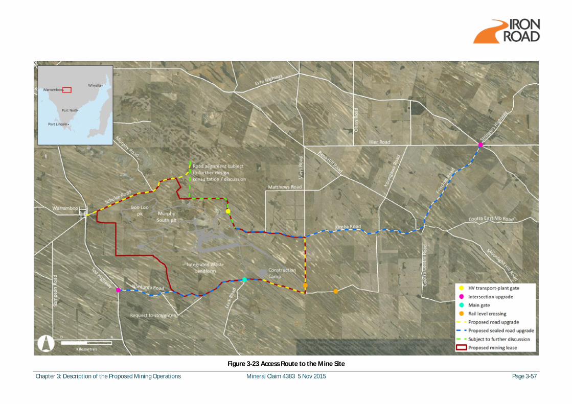
Chapter 3: Description of the Proposed Mining Operations Mineral Claim 4383 5 Nov 2015 Page 3-57
Figure 3-23 Access Route to the Mine Site
Page 3-58 Mineral Claim 4383 5 Nov 2015 Chapter 3: Description of the Proposed Mining Operations
3.6.2 Accommodation, Office and Maintenance Areas
This section describes the accommodation available for employees at the mine site, as well as the administration and maintenance areas available on site. Administration and maintenance areas include induction areas, warehousing, workshops and light and heavy vehicle facilities.
Accommodation
Accommodation for personnel working at the mine site will be provided in one of two locations. During the Construction phase, accommodation for up to 1050 personnel will be provided in a camp at the mine site (the mine construction camp). Once the project has moved into Production phase, approximately 260 permanent employees will be accommodated at the proposed long-term employee village adjacent to Wudinna and the contractor workforce of approximately 300 will be accommodated at the mine contractor camp (which will be the construction camp adapted as required). The long-term employee village will provide accommodation for approximately 300 personnel to accommodate visiting staff or others as required in addition to the anticipated 260 mine site workforce. The mine site operational camp will provide accommodation for the contractor and maintenance or shut down workforce of up to 600 employees. Refer to Section 3.8.1 for further information in relation to the mine workforce. The mine site construction camp will be located east of the Lock Road/Nantuma Road intersection. Following completion of the Construction phase, the construction camp will be partially decommissioned and altered to meet the requirements of the production workforce. The operation camp will utilise the remaining infrastructure from the construction camp and be located at the same location. Access to the mine site camp will be from Nantuma Road and the Main Gate. The camp will provide housing, dining, laundry and recreation facilities for the residents. The camp site will be fenced with a controlled entrance. Generally, all buildings will be of a pre-fabricated modular construction, transported to and installed on the site. The buildings will likely be finished in colorbond steel with zincalume roofing. An indicative layout of the mine camp is shown on Figure 3-24. The camp will include the following facilities:
· Dining and kitchen building · A licenced ‘wet mess’ · Generators with associated fuel storage to provide power · Communications facility, including phone and internet access · Access road and car parking · Laundry · Waste disposal · Bus parking, bus stop area and car parking areas · Recreation building, gym and multi-purpose sports court
The long-term employee village is located north of Wudinna and is subject to approval under the Development Act 1993 in conjunction with the remainder of the CEIP Infrastructure and is therefore not discussed further.

Chapter 3: Description of the Proposed Mining Operations Mineral Claim 4383 5 Nov 2015 Page 3-59
Figure 3-24 Indicative Layout of Mine Site Camp (Source: DoricGroup)
Administration and Induction Areas
The mine site induction area is located adjacent to the security gatehouse at the Main Gate at the intersection of Lock Road and Nantuma Road, as described in Section 3.6.7 below. The administration areas, as illustrated in Figure 3-25, provide office accommodation for the mine site personnel. The administration areas are located adjacent to the ore processing facilities and include an administration office, ablution and change rooms, control room, office and crib. The areas external to the administration areas are unsealed paved hardstand and laydown areas. This external area provides for light vehicle parking, as well as allowing access around the building and provides additional outdoor storage areas. The administration office and control buildings will provide: · Managers offices · Reception and waiting area · Area for work stations and desks · Meeting rooms · Training room · Pre-start meeting room · Central control room · Testing laboratory
Page 3-60 Mineral Claim 4383 5 Nov 2015 Chapter 3: Description of the Proposed Mining Operations
A warehouse and additional offices are also identified on Figure 3-25 and will operate as a storage facility for the processing and stockyard spare parts. It will also provide space for any new augmentation works and general consumables for the mine operation site personnel. The areas external to the warehouse are unsealed paved hardstand and laydown areas. This external area provides for light vehicle parking, as well as allowing access around the building and provides additional outdoor storage areas.
Maintenance Facilities
The following maintenance facilities are incorporated in the mine site layout as illustrated in Figure 3-26:
· Heavy vehicle workshop – incorporating a workshop and refuelling for heavy mine vehicles only · Engineering workshop – facilities to support maintenance of processing and materials handling
infrastructure such as the ore processing facility, conveyors etc. · Light vehicle maintenance facility – incorporating a workshop, refuelling and washdown area for
light vehicles · Wagon and locomotive maintenance buildings – facilities for servicing of wagons and locomotives
Bunding, controlled surface water runoff and hydrocarbon separation will be provided in these facilities, with the collected waste disposed of by a licensed contractor. Hydrocarbon and chemical storage facilities and wash bays will be designed in accordance with Australian Standards, relevant legislation and guidelines, including:
· Stormwater Management for Wash Bays (EPA 517/04 - April 2004) · Bunding and spill management guideline (EPA 2007) · AS 1940-2004: The storage and handling of flammable and combustible liquids · AS 1692-2006: Steel tanks for flammable and combustible liquids · Relevant South Australian legislation
3.6.3 Emergency Services
The emergency services area is proposed to be located centrally within the mine site, adjacent to the ore processing facilities as illustrated in Figure 3-25. It provides facilities for full-time fire management and medical treatment and includes undercover parking for an ambulance and fire assistance vehicle if required. The emergency services area provides:
· Manager’s office and two workstations · Casualty/recovery rooms (two) · Toilets · Covered carport for emergency vehicle (ambulance) · Covered carport for fire appliance (fire assistance vehicle)
The exterior of the emergency services area will be an unsealed paved hardstand and laydown area assigned as a Medevac helipad in the event of an emergency. The main car park within the ore processing facilities area will be primarily utilised for light vehicle and bus parking during mine operations, however can also be utilised as a secondary Medevac helipad in the event on an extreme emergency.
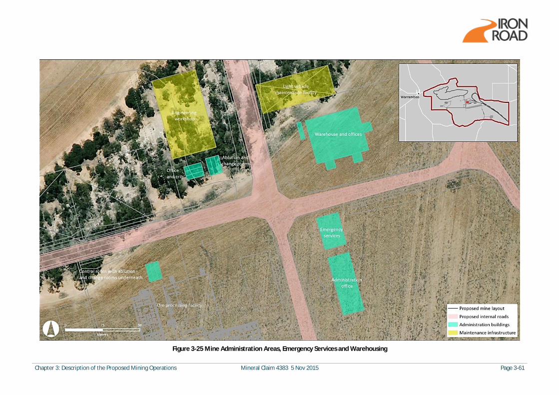
Chapter 3: Description of the Proposed Mining Operations Mineral Claim 4383 5 Nov 2015 Page 3-61
Figure 3-25 Mine Administration Areas, Emergency Services and Warehousing
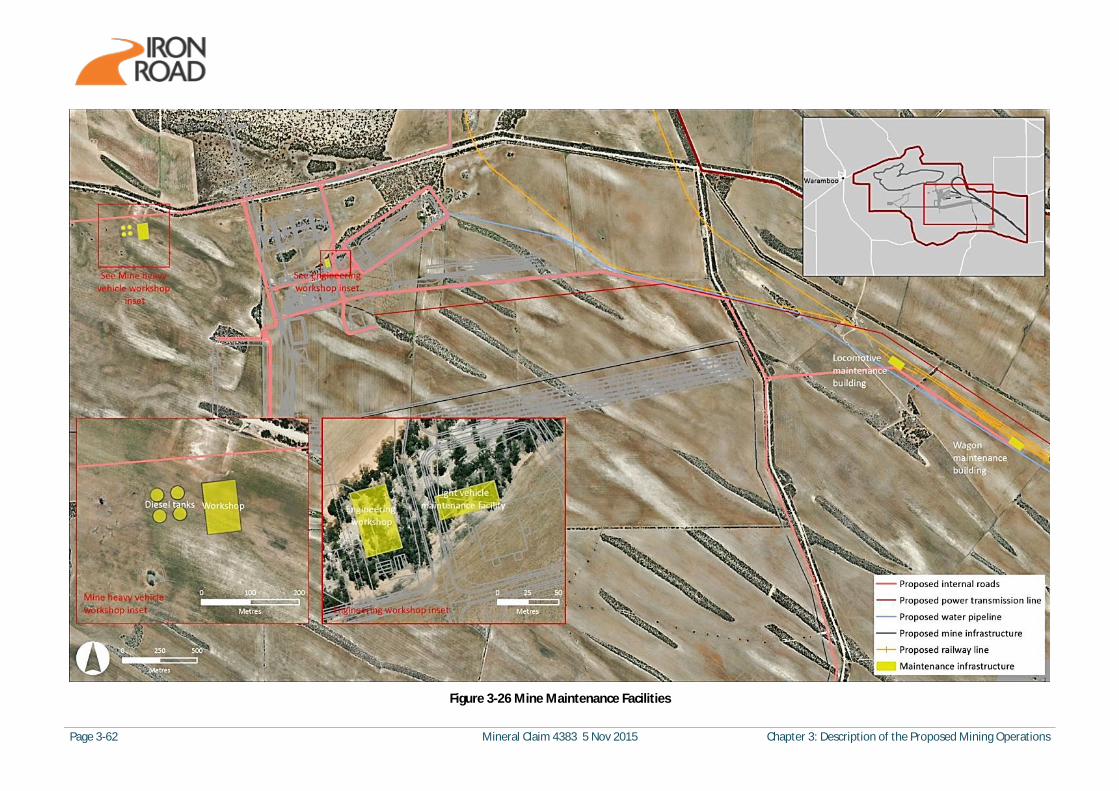
Page 3-62 Mineral Claim 4383 5 Nov 2015 Chapter 3: Description of the Proposed Mining Operations
Figure 3-26 Mine Maintenance Facilities
Chapter 3: Description of the Proposed Mining Operations Mineral Claim 4383 5 Nov 2015 Page 3-63
3.6.4 Public Roads, Services and Utilities
Public Roads
As outlined in Section 3.6.1, a range of public roads will be utilised for access to the mine site and will require upgrading to support anticipated traffic movements. Every effort will be made to minimise disruption and inconvenience. The following road closures will be required where sections of roads are located within the mine site boundary:
· Dolphin Road · Murphy Road · Kimba Road · Lock Road
The estimated numbers of vehicle movements, additional discussion on road closures and potential impacts upon existing traffic and road networks are outlined in Chapter 8.
Existing Services and Relocations
The following services and utilities enter the mine site and are illustrated in Figure 3-27:
· SA Water pipeline along Kimba Road · 19 kV SA Power Network overhead power lines run along Kimba Road, connect to existing
dwellings within the mine site boundary and through the mine site from Kimba Road to a number of dwellings to the north and south of the boundary
· 132 kV SA Power Network overhead power line runs through the mine site to the west of the mine pit
Telstra copper connections to existing dwellings within the mine site boundary are not illustrated in Figure 3-27. As is the case with road changes, every effort will be made to minimise disruption and inconvenience, recognising that these services are not under the direct control of Iron Road. The following utilities relocations are proposed:
· Prior to decommissioning the Kimba Road SA Water pipeline and following final negotiation with SA Water it is proposed that a new DN 150 CICL water pipeline will be installed around the mine site northern boundary. Re-connection will be made into the Kimba Road pipeline at the eastern and western boundary extents, to maintain regional supply.
· Once electricity is available from the new power transmission line to be constructed along the proposed infrastructure corridor, the 19 kV power lines will progressively be isolated and removed. New power lines will be installed prior to disconnection of the existing services, where required, to maintain service continuity to properties outside the mine site.
· It is proposed that the 132 kV transmission line that crosses the western end of the mine site be isolated at the mine site boundary and removed and a new line installed around the mine site boundary.
· It is proposed that the majority of the Telstra services will be terminated at the mine site boundary. Service realignments will be undertaken to existing properties outside the mine site boundary including on Nantuma and Kimba Road.

Page 3-64 Mineral Claim 4383 5 Nov 2015 Chapter 3: Description of the Proposed Mining Operations
Figure 3-27 Existing Public Roads, Water Supply and Electricity Network
Chapter 3: Description of the Proposed Mining Operations Mineral Claim 4383 5 Nov 2015 Page 3-65
New Services and Utilities
Electricity and water will be supplied to the mine site via the infrastructure corridor. Electricity will be supplied via a 275 kV power transmission line from the Yadnarie substation. Water will be sourced from saline groundwater supplies, taken from a proposed borefield approximately 7 km west of Kiepla. Small volumes of groundwater will also be sourced from mine pit dewatering. Within the mine site, the following utilities are proposed to be provided:
· Groundwater supply from the Kielpa borefield, including storage ponds · Reverse osmosis plant for the desalinisation of groundwater, including storage and potable water
distribution infrastructure with brine output to the process water runoff dam · Fire water reticulation and pump station, including fire hydrants and fire brigade booster
assemblies · Wash down hoses, dust suppression spray bar and water carts · Sewerage reticulation, pump stations and treatment · Surface water runoff containment ponds · Process water storage, treatment and recirculation · Compressed air (within workshops only) · Electrical distribution · Emergency backup power supply
All utilities within the mine site are designed to accommodate demand peaks such as daily start-up, shift breaks (crib) and end of shift periods.
3.6.5 Visual Screening
Landscaping will be incorporated in association with each project component utilising locally indigenous species. The landscaping will be used to provide visual relief and partial screening of infrastructure within and around the mine site boundary where required.
3.6.6 Fuel and Chemical Storage
Fuel and chemicals will be stored at the following locations (refer to Figure 3-26):
· Heavy vehicle workshop · Engineering workshop · Light vehicle maintenance facility · Wagon and locomotive maintenance buildings · Bulk explosive storage and preparation area (within the explosives storage and manufacturing
facility, refer to Table 3-8)
Fuel and chemical storage facilities will be designed and managed in accordance with the following guidelines and standards:
· Bunding and spill management guideline (EPA 2007a) · AS 1940-2004: The storage and handling of flammable and combustible liquids · AS 1692-2006: Steel tanks for flammable and combustible liquids · Relevant South Australian legislation
Page 3-66 Mineral Claim 4383 5 Nov 2015 Chapter 3: Description of the Proposed Mining Operations
Light and Heavy Vehicle Refuelling Facilities
The light vehicle refuelling facility will be capable of unloading, storing and dispensing diesel fuel to light vehicles and is co-located within the light vehicle maintenance facility east of the ore processing facility. The heavy vehicle refuelling facility will be capable of unloading, storing and dispensing diesel fuel for heavy vehicles on site and will be co-located with the heavy vehicle workshop, west of the ore processing facility. Both fuel unloading areas include a covered concrete slab, with filtration and oil/water separation facilities. Above-ground storage tanks will be self-bunded, mounted on pad footings and incorporate all piping, valving and instrumentation to facilitate the use of a single pump station. A pump station and metering system will pump fuel from storage tanks to the dispensing point. The light vehicle fuel dispensing point is from a standard bowser on a bunded concrete slab. The heavy vehicle fuel dispensing point will consist of a high flow hose and nozzle with articulated arm and access platforms to facilitate maintenance.
3.6.7 Site Security
The majority of the mine site boundary will be fenced with seven strand stock fencing with barbed wire at the top. Rural standard gates will be installed at Kimba Road, Murphy Road and Lock Road (north of Kimba Road) for access only in the event of an emergency. A staffed gatehouse, with boom gates operating 24 hours a day will be located at the Main Gate (at the Lock Road/Nantuma Road intersection) to control unauthorised access to the mine site and control the movement of approved vehicles entering/exiting the mine site. The gatehouse building will provide:
· Security office with two work stations · Drug and alcohol testing room · Toilet · Kitchenette · Car parking and vehicle layby at both the entrance and exit of the mine site
Within the mine site, additional security will be located at the explosives storage and manufacturing facility and the high voltage substation. The high voltage substation compound will be fenced with a 2.1 m chainlink fence incorporating personnel and vehicle access gates. Similarly, the explosive magazine and bulk explosive storage and preparation areas will be secure facilities, separately fenced with a 2.1 m chainlink fence incorporating locked and monitored gates. The explosives storage and manufacturing facility will also incorporate lighting and closed circuit television for security monitoring. Site fencing and security across the mine site is depicted in Figure 3-28.

Chapter 3: Description of the Proposed Mining Operations Mineral Claim 4383 5 Nov 2015 Page 3-67
Figure 3-28 Site Fencing and Site Security

Page 3-68 Mineral Claim 4383 5 Nov 2015 Chapter 3: Description of the Proposed Mining Operations
3.6.8 Stormwater Management
As described in more detail in Chapter 18, the landscape incorporating the mine site is characterised by sand dunes with no existing drainage lines or creek lines. Most rainfall infiltrates directly into the soil. Prolonged heavy rainfall events may generate run-off which collects in natural swales between wide dunes. There is currently no known capture or retention of surface water for potable, agriculture, or industrial purposes within catchments intersected by the mine site. The design of surface water management controls has been undertaken with the overarching aim of maintaining the natural flow regime and preventing sediment runoff from the mine site. Site-wide design and management measures for surface water and stormwater management are detailed in Chapter 18 and include bunding of vehicle wash down, fuel and chemical storage areas, culverts at low points of roads to allow natural movement of surface water runoff and installation of rock armour downstream of culverts to minimise soil erosion.
Management of Stormwater Runoff from the IWL
As summarised in Chapter 18 and Section 3.5.2 above, the slopes of the IWL will incorporate a series of berms and back-benches to control runoff and encourage infiltration into the landform. The landform is designed as a water retaining structure (store and release) to limit the amount of runoff that will occur. The top surface of the IWL will be shaped and bunded if required to prevent runoff down the face of the outer slopes. As summarised in Chapter 19, seepage through the landform to groundwater will be negligible. The water will be absorbed by the soils, drawn in by vegetation and lost to evaporation or evapotranspiration. The outer perimeter of the IWL will be bunded in those areas where stormwater run-off has the potential to leave the mine site to ensure infiltration of runoff. The IWL will be rehabilitated progressively during the project, reducing the area exposed and prone to erosion. Vegetation will be established on the top surface and slopes of the IWL to control surface water flows, encourage infiltration and facilitate nutrient and water cycling.
3.7 Mine Completion Following the Production phase, a mine closure phase will be completed prior to relinquishment of the proposed mining lease at mine completion. The closure phase will involve decommissioning of site infrastructure, any works required to stabilise (make-safe) the mine pit and prevent unauthorised entry and final rehabilitation of the IWL. At mine completion the mine site will comprise:
· Rehabilitated land where surface infrastructure and buildings have been decommissioned and removed
· Infrastructure retained for future use · A mine pit which will be stabilised and become a pit lake as rainwater collects and groundwater
discharges into the pit · An IWL with a surface cover which allows successful revegetation
These components of the mine site at completion are described below.

Chapter 3: Description of the Proposed Mining Operations Mineral Claim 4383 5 Nov 2015 Page 3-69
3.7.1 Surface Infrastructure and Buildings
Based on liaison with Wudinna DC, local landowners and other key stakeholders during the late stages of mining, it will be determined which site infrastructure is of value and which will be decommissioned and removed from site. It is expected that the railway line and loop and transmission line will be retained based on negotiation with the State Government and potential private investors for future use. Decommissioning and removal of site infrastructure would involve site assessment and remediation planning, including removal of fuel and chemical storage and wastewater treatment facilities in accordance with the relevant legislation and standards.
3.7.2 Mine Pit
At mine completion it has been estimated that the Murphy South pit will be approximately 6.2 km long, 1.4 km wide and 630 m deep and the Boo Loo pit will be approximately 3 km long, 1 km wide and 325 m deep.
Mine Pit Stability
The Work Health and Safety Regulations 2012 require that at the time of closure of the mine, Iron Road must ensure that the mine is safe, including prevention of unauthorised entry. Prior to mine closure, a detailed assessment of slope stability will be made based on observations of the performance of the pit walls and data collected during excavation of the mine pit. It is considered that in the unlikely event of mine pit instability occurring, the severity of consequence can be adequately managed by the construction of safety bund walls placed at an appropriate distance from the mine pit edge.
Concept design criteria for safety bund walls
A guideline produced by the Western Australian Department of Industry and Resources (DIR 1997) provides simple and generic design criteria for the location and construction of mine pit safety bund walls that allow for the normal variation of the factors affecting long-term stability. The guideline requires that the abandonment bund wall is constructed outside the area designated as the potentially unstable pit edge zone (defined Figure 3-29). Case history data from slope failure and tension crack measurements around open pits in Western Australia suggest that the overall angle defining the maximum potentially unstable rock mass is primarily dependent on whether the pit wall consists of weathered (oxidised) rock or unweathered (unoxidised) rock. These case data also suggest that the maximum area of potentially unstable rock mass for failure through each class of rock can be defined by two separate design angles:
· 25° for soil and weathered rock · 45° for unweathered rock
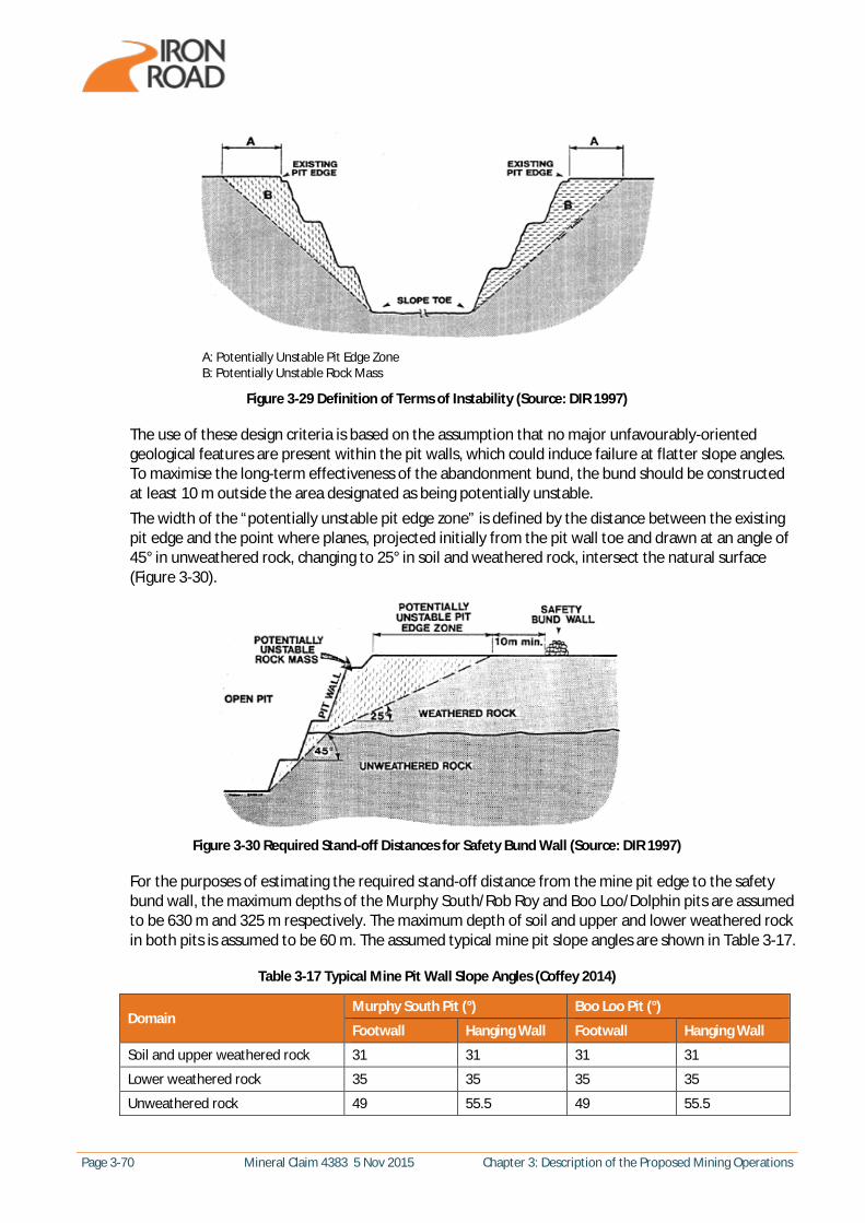
Page 3-70 Mineral Claim 4383 5 Nov 2015 Chapter 3: Description of the Proposed Mining Operations
A: Potentially Unstable Pit Edge Zone B: Potentially Unstable Rock Mass
Figure 3-29 Definition of Terms of Instability (Source: DIR 1997)
The use of these design criteria is based on the assumption that no major unfavourably-oriented geological features are present within the pit walls, which could induce failure at flatter slope angles. To maximise the long-term effectiveness of the abandonment bund, the bund should be constructed at least 10 m outside the area designated as being potentially unstable. The width of the “potentially unstable pit edge zone” is defined by the distance between the existing pit edge and the point where planes, projected initially from the pit wall toe and drawn at an angle of 45° in unweathered rock, changing to 25° in soil and weathered rock, intersect the natural surface (Figure 3-30).
Figure 3-30 Required Stand-off Distances for Safety Bund Wall (Source: DIR 1997)
For the purposes of estimating the required stand-off distance from the mine pit edge to the safety bund wall, the maximum depths of the Murphy South/Rob Roy and Boo Loo/Dolphin pits are assumed to be 630 m and 325 m respectively. The maximum depth of soil and upper and lower weathered rock in both pits is assumed to be 60 m. The assumed typical mine pit slope angles are shown in Table 3-17.
Table 3-17 Typical Mine Pit Wall Slope Angles (Coffey 2014)
Domain Murphy South Pit (°) Boo Loo Pit (°)
Footwall Hanging Wall Footwall Hanging Wall
Soil and upper weathered rock 31 31 31 31
Lower weathered rock 35 35 35 35
Unweathered rock 49 55.5 49 55.5

Chapter 3: Description of the Proposed Mining Operations Mineral Claim 4383 5 Nov 2015 Page 3-71
The horizontal distances from the toe to the crest of both the foot walls and hanging walls of both pits are shown in Table 3-18. The depths of the soil/upper weathered rock is assumed to be 30 m and the depth of the lower weathered rock is also assumed to be 30 m.
Table 3-18 Horizontal Distance from Toe to Crest of Pit Slope
Murphy South Pit (m) Boo Loo Pit (m)
Footwall Hanging Wall Footwall Hanging Wall
590 485 320 275 Based on the criteria shown in Figure 3-30, the bund wall for the Murphy South pit would lie approximately 710 m horizontally from the toe of the mine pit walls, while the bund wall for the toe of the Boo Loo pit would lie approximately 405 m horizontally from the toe of the mine pit walls. The required stand-off distances from the mine pit edge to the safety bund wall are presented in Table 3-19.
Table 3-19 Required Stand-off Distances from Mine Pit Edge to Safety Bund Wall
Murphy South Pit (m) Boo Loo Pit (m)
Footwall Hanging Wall Footwall Hanging Wall 120 225 85 130
Figure 3-31 Indicative Safety Bund Wall Offsets from Edge of Mine Pit
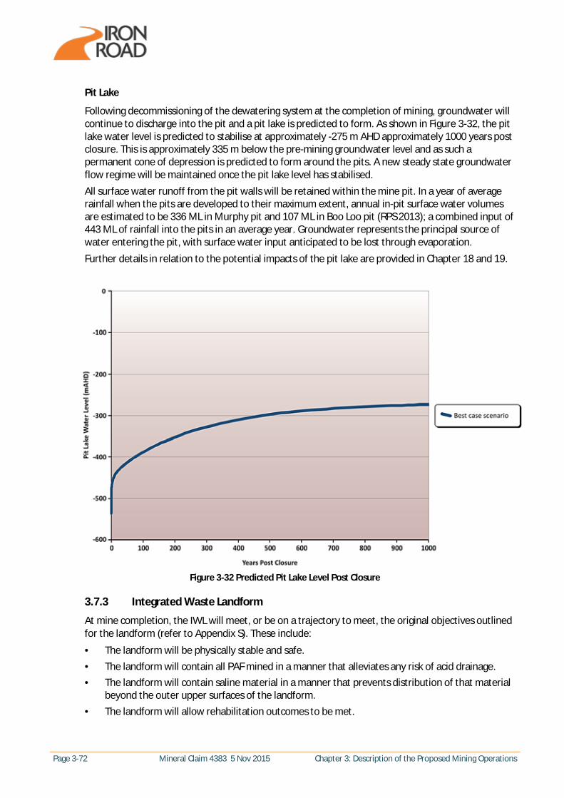
Page 3-72 Mineral Claim 4383 5 Nov 2015 Chapter 3: Description of the Proposed Mining Operations
Pit Lake
Following decommissioning of the dewatering system at the completion of mining, groundwater will continue to discharge into the pit and a pit lake is predicted to form. As shown in Figure 3-32, the pit lake water level is predicted to stabilise at approximately -275 m AHD approximately 1000 years post closure. This is approximately 335 m below the pre-mining groundwater level and as such a permanent cone of depression is predicted to form around the pits. A new steady state groundwater flow regime will be maintained once the pit lake level has stabilised. All surface water runoff from the pit walls will be retained within the mine pit. In a year of average rainfall when the pits are developed to their maximum extent, annual in-pit surface water volumes are estimated to be 336 ML in Murphy pit and 107 ML in Boo Loo pit (RPS 2013); a combined input of 443 ML of rainfall into the pits in an average year. Groundwater represents the principal source of water entering the pit, with surface water input anticipated to be lost through evaporation. Further details in relation to the potential impacts of the pit lake are provided in Chapter 18 and 19.
Figure 3-32 Predicted Pit Lake Level Post Closure
3.7.3 Integrated Waste Landform
At mine completion, the IWL will meet, or be on a trajectory to meet, the original objectives outlined for the landform (refer to Appendix S). These include:
· The landform will be physically stable and safe. · The landform will contain all PAF mined in a manner that alleviates any risk of acid drainage. · The landform will contain saline material in a manner that prevents distribution of that material
beyond the outer upper surfaces of the landform. · The landform will allow rehabilitation outcomes to be met.
Chapter 3: Description of the Proposed Mining Operations Mineral Claim 4383 5 Nov 2015 Page 3-73
The management of surface water flow is critical to the long-term stability of any constructed landform. At mine completion, the IWL should demonstrate that surface water flows are not being concentrated and that appropriate drainage features on the upper surface, berms and bunds are preventing over-topping onto constructed slopes and infiltration of rainfall for storage within the upper soil profile for plant root access and subsequent growth is occurring. The landform should be demonstrating no evidence of excessive or localised erosion or sedimentation. Appropriate placement of suitable topsoil, subsoil within the stabilising rock matrix on the cover surface should facilitate effective revegetation or rehabilitation by native vegetation on the slopes and batters. At mine completion, early slope rehabilitation should demonstrate self-sustaining ecosystems with evidence of water and nutrient cycling and recruitment by key plant species.
3.7.4 Land Use Options
In areas of the mine site that have been rehabilitated or were unused, it is anticipated that similar land uses to current (e.g. agricultural uses) will re-commence post closure with the benefit of the availability of additional infrastructure, including the railway line and transmission line. Alternative land use options including vegetation cover for the IWL are detailed in the Conceptual IWL Design for Rehabilitation and Closure report (refer to Appendix S). In summary, alternative final land uses may include agricultural production (cropping and grazing), agroforestry (multiple land use), a native woodland ecosystem for conservation or mixed use vegetation. Consideration of these alternative final land use options will incorporate an understanding of climatic influences and climate change upon long-term productivity and sustainability, particularly for options such as cropping or agroforestry. Increasing aridity is predicted in the bulk of southern Australia and factors such as declining rainfall and higher evaporation rates are predicted to gradually change the nature of local land use. The validity of alternative land use options, in terms of achieving stakeholder expectations and the primary objectives of a stable, rehabilitated landform are all to be considered by investigation and research, as part of the forward work plan during the investigation, construction and operational stages of the CEIP. Post closure land use options will be discussed in detail with the Wudinna DC, State Government, local landowners and other key stakeholders during the later stages of mining.
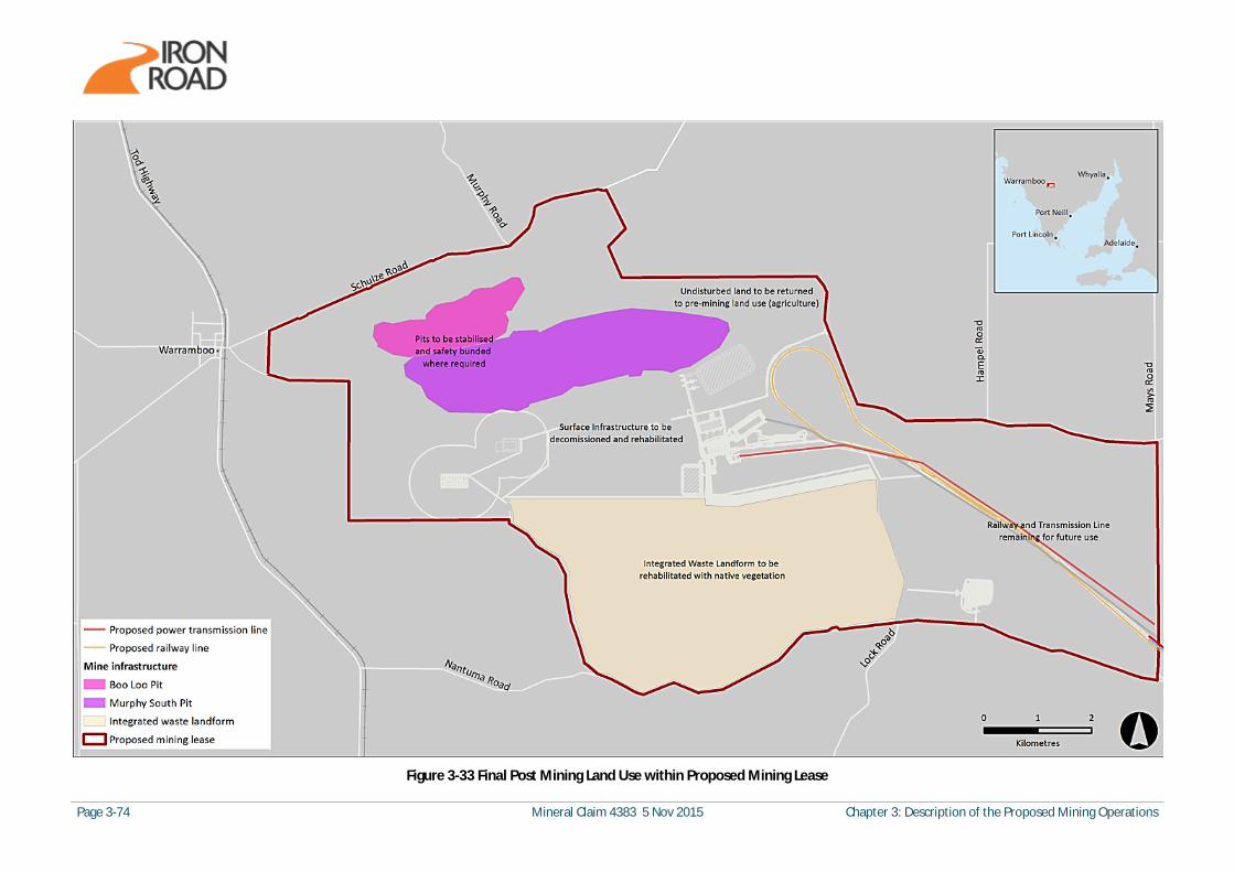
Page 3-74 Mineral Claim 4383 5 Nov 2015 Chapter 3: Description of the Proposed Mining Operations
Figure 3-33 Final Post Mining Land Use within Proposed Mining Lease

Chapter 3: Description of the Proposed Mining Operations Mineral Claim 4383 5 Nov 2015 Page 3-75
Figure 3-34 Final Post Mining Cross Sections
(N.B. ten times vertical exaggeration)

Page 3-76 Mineral Claim 4383 5 Nov 2015 Chapter 3: Description of the Proposed Mining Operations
3.7.5 Native Vegetation Cover
As described in Chapter 12, approximately 87% of the proposed mine site is cleared agricultural land and remnant vegetation cover is limited to isolated and fragmented patches of mallee vegetation from the Koongawa Interim Biogeographic Regionalisation for Australia vegetation association (approximately 1,118 ha in total). Clearance of native vegetation is prohibited under the Native Vegetation Act 1991 without approval from the Native Vegetation Council, delegated to DSD for mining proposals. Approval of native vegetation clearance requires agreement of a commensurate Significant Environmental Benefit (SEB) to offset the impacts of clearance. Native vegetation to be cleared and retained is also detailed in Chapter 12, Vegetation and Weeds, in particular Figure 12-6. Clearance of vegetation will be required for the establishment and maintenance of mine infrastructure, transport routes, ore extraction and development of the IWL. The approximate total native vegetation clearance required within the mine site, subject to approval, will be 602 ha, which is approximately 54% of the existing native vegetation cover within the mine site. During the life of the mine, landscaping for visual screening purposes and rehabilitation within the mine site (e.g. on the slopes of the IWL) are expected to result in increased native vegetation cover which may form a part of the SEB requirements, subject to negotiation and approval by DSD. Therefore at mine completion, rehabilitation with native vegetation in strategic areas of the mine site will have largely been completed.
3.8 Resource Inputs
3.8.1 Workforce and Hours of Operation
The majority of the construction workforce (during the Construction phase) would be in contract positions and construction activities would occur nominally seven days per week and up to 12 hours per day. It is anticipated that the majority of the construction workforce would work 12-hour shifts on a fly-in/fly-out (FIFO) or drive-in/drive-out (DIDO) basis and be accommodated at the construction camp at the mine site (refer to Section 3.6.2). While it is Iron Road’s preference to employ locally-based workers at the mine, it is recognised that in order to meet workforce requirements, at least initially, the majority of the operational workforce may be FIFO or DIDO. The operational workforce would include employees, many of which would be accommodated at the long-term employee village adjacent to Wudinna and contractors, who would be accommodated in the construction camp. The majority of contractors and employees engaged in operations at the mine would work on rosters of two weeks on and one week off, in shifts, with the mine operating on a 24 hours per day, 7 days per week, 365 days per year basis. As listed in Table 3-20, the peak construction workforce to be accommodated at the proposed mine site would be approximately 1050 personnel (including workforce for construction of the long-term employee village) and an operational workforce of approximately 560 personnel. In addition, a short-term workforce of around 300 contractors would be engaged periodically for routine maintenance shutdowns.

Chapter 3: Description of the Proposed Mining Operations Mineral Claim 4383 5 Nov 2015 Page 3-77
Table 3-20 Projected Peak Workforce at the Proposed Mine
Project Phase Mine Head Office Total
Construction 10501 5402 1590
Operations
- Employees 260 60 320
- Contractors 300 - 300
- Total Operations 560 60 620
Shutdown 3003 - 300
1. Includes the workforce required to construct the long-term employee village. 2. Includes workforce managing construction of mine as well as infrastructure (long-term employee village, railway, borefield, transmission line and port). 3. Not part of the permanent workforce as this work would be undertaken periodically as part of an annualised task.
3.8.2 Energy Sources
Energy will be sourced from the electricity grid and diesel fuel.
Electricity Use
During the Construction phase, electricity will be sourced temporarily from the existing network of 19 kV SA Power Network overhead power lines within the mine site boundary (within the capacity of the power lines) and from diesel generators where required. The estimated total electricity consumption during this phase (over 3 years) is 115 MWh. For the Production phase, electricity will be supplied via a 275 kV power transmission line from the Yadnarie substation. The approximate peak electricity consumption will be 2,569 GWh. The power transmission line is subject to separate approval under the Development Act 1993. The estimated electricity use and associated calculated greenhouse gas (GHG) emissions are listed in Table 3-21.
Table 3-21 Electricity Use and Calculated GHG Emissions
Project Phase Electricity Use Estimated GHG Emissions1
Construction Total for 3 years of 115 MWh 70 t CO2-e
Production Peak annual demand of 2,569 GWh 1,567,090 t CO2-e/annum
1. Emission factor of 0.61 t CO2-e/MWh
Diesel Use
The estimated mobile fleet diesel use during the Construction phase is 10 GL over three years and during the Production phase the approximate peak annual use will be 26,200 kL. Mobile fleet diesel use and the associated calculated GHG emissions are listed in Table 3-22.
Table 3-22 Diesel Use and Calculated GHG Emissions
Project Phase Diesel Use Estimated GHG Emissions1
Construction Total for 3 years of 10 GL 26,977 t CO2-e
Production Peak annual demand of 26,200 kL 70,691 t CO2-e/annum
1. Emission factors (kg CO2-e/GJ) of 69.2 for CO2, 0.2 for CH4 and 0.5 for N2O

Page 3-78 Mineral Claim 4383 5 Nov 2015 Chapter 3: Description of the Proposed Mining Operations
Energy Efficiency
The design of the CEIP has incorporated a number of energy efficiency measures that have directly contributed to a reduction in projected energy demand during construction and operations, including:
· Reduction in size of truck fleet – The change from diesel-powered conventional load and haul mining to the proposed in-pit crushing and conveying mining method has significantly reduced the size of the haul truck fleet required from approximately 93 to 12 trucks, while taking advantage of greener grid-based electricity as the mining energy supply.
· Optimisation of blasting techniques – Rock and ore blasting techniques have been optimised to minimise the energy consumed in the primary crushing phase of the mining process.
· Water source from borefield – Initial designs of a desalination plant located near Elliston or a water supply and desalination plant at the proposed port site required significantly more power to pump the water requirements to the mine site. The current proposal pumps water approximately half the distance of earlier designs.
· Optimisation of processing plant operations and stacked tailings – The optimisation of the processing plant operations and stacked tailings, including extensive dewatering of the tailings and reclamation of the water, significantly reduces the need for additional water and associated pumping energy requirements.
· Integration of tailings and rock storage facilities – The integration of the tailings storage facility and rock storage facilities, will significantly reduce the project footprint and thus the carbon stocks that would be disturbed during land clearing, saving around 100,000 t of CO2-e over the life of the operation.
Further optimisation to reduce energy demand will include:
· Water balance optimisation – Further optimisation of the mine water balance, including the application of water-efficient fixtures, fittings and appliances and the capture and reuse of stormwater together with water sensitive urban design will result in transfer of less water from the remote borefield, thus reducing energy demand.
· Incorporation of energy-efficient design elements and small scale renewable – Energy efficient design elements will be incorporated within the accommodation, administration and workshop facilities to reduce electricity demands (including the use of energy-efficient fixtures, fittings and appliances and the use of passive solar design elements within the plant and accommodation facilities) and small scale renewable options will be considered, where practicable, such as solar powered monitoring stations and solar power for site administration, accommodation and workshop facilities.
· Minimisation of fuel consumption – Fuel consumption will be minimised by sourcing products locally wherever practicable to minimise travel distances and selecting efficient plant and equipment.
· Offsets – Iron Road will investigate opportunities for the application of greenhouse emission offset programmes under the Emissions Reduction Fund and associated Carbon Farming Initiative.
3.8.3 Water Sources
The majority of water required for the mining operations will be saline water sourced from the borefield. This will be supplemented by small variable volumes of rainfall run-off from mine pit dewatering, with rainwater captured and used where possible. On-site treatment of saline water via a reverse osmosis desalination plant will be used to obtain freshwater for final filtering of the concentrate and potable water for administrative and accommodation areas. Expected annual usage requirements for each water source during operations are summarised in Table 3-23.
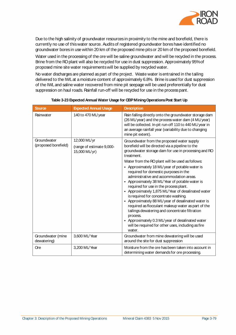
Chapter 3: Description of the Proposed Mining Operations Mineral Claim 4383 5 Nov 2015 Page 3-79
Due to the high salinity of groundwater resources in proximity to the mine and borefield, there is currently no use of this water source. Audits of registered groundwater bores have identified no groundwater bores in use within 20 km of the proposed mine pits or 20 km of the proposed borefield. Water used in the processing of the ore will be saline groundwater and will be recycled in the process. Brine from the RO plant will also be recycled for use in dust suppression. Approximately 95% of proposed mine site water requirements will be supplied by recycled water. No water discharges are planned as part of the project. Waste water is entrained in the tailing delivered to the IWL at a moisture content of approximately 6.8%. Brine is used for dust suppression of the IWL and saline water recovered from mine pit seepage will be used preferentially for dust suppression on haul roads. Rainfall run-off will be recycled for use in the process pant.
Table 3-23 Expected Annual Water Usage for CEIP Mining Operations Post Start Up
Source Expected Annual Usage Description
Rainwater 140 to 470 ML/year Rain falling directly onto the groundwater storage dam (26 ML/year) and the process water dam (4 ML/year) will be collected. In-pit run-off 110 to 440 ML/year in an average rainfall year (variability due to changing mine pit extent).
Groundwater (proposed borefield)
12,000 ML/yr
(range of estimate 9,000-15,000 ML/yr)
Groundwater from the proposed water supply borefield will be directed via a pipeline to the groundwater storage dam for use in processing and RO treatment. Water from the RO plant will be used as follows: · Approximately 18 ML/year of potable water is
required for domestic purposes in the administrative and accommodation areas.
· Approximately 38 ML/Year of potable water is required for use in the process plant.
· Approximately 1,875 ML/Year of desalinated water is required for concentrate washing.
· Approximately 88 ML/year of desalinated water is required as flocculant makeup water as part of the tailings dewatering and concentrate filtration process.
· Approximately 0.3 ML/year of desalinated water will be required for other uses, including as fire water.
Groundwater (mine dewatering)
3,600 ML/Year Groundwater from mine dewatering will be used around the site for dust suppression
Ore 3,200 ML/Year Moisture from the ore has been taken into account in determining water demands for ore processing.

Page 3-80 Mineral Claim 4383 5 Nov 2015 Chapter 3: Description of the Proposed Mining Operations
This page has been left blank intentionally.
Related Documents