Chapter 3 A survey of steganographic techniques Neil F. Johnson and Stefan C. Katzenbeisser Many different steganographic methods have been proposed during the last few years; most of them can be seen as substitution systems. Such methods try to substitute redundant parts of a signal with a secret message (as presented in Section 2.3); their main disadvantage is the relative weakness against cover modifications. Recently, the development of new robust watermarking techniques led to advances in the construction of robust and secure steganography systems. Therefore, some of the methods presented here are strongly related to watermarking techniques of Chapter 6. There are several approaches in classifying steganographic systems. One could categorize them according to the type of covers used for secret communication. A classification according to the cover modifications applied in the embedding process is another possibility. We want to follow the second approach and group stegano- graphic methods in six categories, although in some cases an exact classification is not possible: Substitution systems substitute redundant parts of a cover with a secret message; Transform domain techniques embed secret information in a transform space of the signal (e.g., in the frequency domain); Spread spectrum techniques adopt ideas from spread spectrum commu- nication; 43

Welcome message from author
This document is posted to help you gain knowledge. Please leave a comment to let me know what you think about it! Share it to your friends and learn new things together.
Transcript
Chapter 3
A survey of steganographic techniques
Neil F. Johnson and Stefan C. Katzenbeisser
Many different steganographic methods have been proposed during the last fewyears; most of them can be seen as substitution systems. Such methods try tosubstitute redundant parts of a signal with a secret message (as presented in Section2.3); their main disadvantage is the relative weakness against cover modifications.Recently, the development of new robust watermarking techniques led to advancesin the construction of robust and secure steganography systems. Therefore, someof the methods presented here are strongly related to watermarking techniques ofChapter 6.
There are several approaches in classifying steganographic systems. One couldcategorize them according to the type of covers used for secret communication. Aclassification according to the cover modifications applied in the embedding processis another possibility. We want to follow the second approach and group stegano-graphic methods in six categories, although in some cases an exact classification isnot possible:
Substitution systems substitute redundant parts of a cover with a secretmessage;Transform domain techniques embed secret information in a transformspace of the signal (e.g., in the frequency domain);Spread spectrum techniques adopt ideas from spread spectrum commu-nication;
43
44 Information hiding techniques for steganography and digital watermarking
Statistical methods encode information by changing several statistical prop-erties of a cover and use hypothesis testing in the extraction process;Distortion techniques store information by signal distortion and measurethe deviation from the original cover in the decoding step;Cover generation methods encode information in the way a cover for secretcommunication is created.
In the following sections these six categories will be discussed.
3.1 PRELIMINARY DEFINITIONS
Throughout the following sections we want to refer to the cover used in the embed-ding step as c. We will further assume (without loss of generality) that any covercan be represented by a sequence of numbers ci of length `(c) (i.e., 1 ≤ i ≤ `(c)). Inthe case of digital sound this could be just the sequence of samples over time; in thecase of a digital image, a sequence can be obtained by vectorizing the image (i.e.,by lining up all pixels in a left-to-right and top-to-bottom order). Possible valuesof ci are {0, 1} in the case of binary images or integers greater than 0 and less than256 in the case of quantized images or sound. We will denote the stego-object by swhich is again a sequence si of length `(c).
Sometimes we have to index all cover-elements ci; we will use the symbol jfor such an index. If the index is itself indexed by some set, we use the notationji. When we refer to the jith cover-element we mean cji
. We will refer to a stego-key as k; the structure of k will be explained separately in each steganographicapplication. The secret message will be denoted by m, the length of m by `(m),and the bits forming m by mi, 1 ≤ i ≤ `(m). Unless otherwise stated, we assumethat mi ∈ {0, 1}.
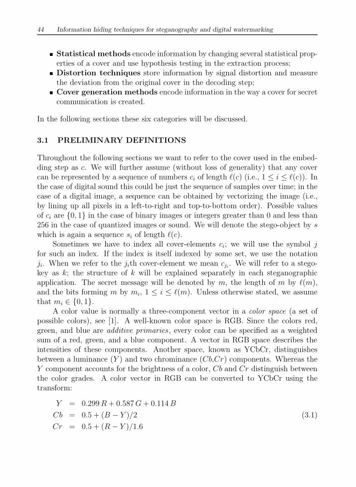
A color value is normally a three-component vector in a color space (a set ofpossible colors), see [1]. A well-known color space is RGB. Since the colors red,green, and blue are additive primaries , every color can be specified as a weightedsum of a red, green, and a blue component. A vector in RGB space describes theintensities of these components. Another space, known as YCbCr, distinguishesbetween a luminance (Y ) and two chrominance (Cb,Cr) components. Whereas theY component accounts for the brightness of a color, Cb and Cr distinguish betweenthe color grades. A color vector in RGB can be converted to YCbCr using thetransform:
Y = 0.299 R + 0.587 G + 0.114 B
Cb = 0.5 + (B − Y )/2 (3.1)
Cr = 0.5 + (R − Y )/1.6

A survey of steganographic techniques 45
An image C is a discrete function assigning a color vector (of any color space) c(x, y)to every pixel (x, y).
3.2 SUBSTITUTION SYSTEMS AND BITPLANE TOOLS
A number of methods exist for hiding information in various media. These meth-ods range from LSB coding—also known as bitplane or noise insertion tools—manipulation of image or compression algorithms to modification of image proper-ties such as luminance. Basic substitution systems try to encode secret informationby substituting insignificant parts of the cover by secret message bits; the receivercan extract the information if he has knowledge of the positions where secret in-formation has been embedded. Since only minor modifications are made in theembedding process, the sender assumes that they will not be noticed by a passiveattacker.
3.2.1 Least significant bit substitution
Bitplane tools encompass methods that apply LSB insertion and noise manipulation.These approaches are common in steganography and are relatively easy to applyin image and audio [2–6]. A surprising amount of information can be hidden withlittle, if any, perceptible impact to the carriers [5, 7, 8].
Sample tools used in this group include StegoDos [9], S-Tools [10], Mandelsteg[11], EzStego [12], Hide and Seek [13], Hide4PGP [14], White Noise Storm [15], andSteganos [16]. The image formats typically used in such steganography methodsare lossless and the data can be directly manipulated and recovered. Some of theseprograms apply compression and encryption in addition to steganography services.These services provide better security of the hidden data. Even so, the bitplanemethods are rather brittle and vulnerable to corruption due to small changes to thecarrier.
The embedding process consists of choosing a subset {j1, . . . , j`(m)} of cover-elements and performing the substitution operation cji
� mi on them, which ex-changes the LSB of cji
by mi (mi can either be 1 or 0). One could also imagine asubstitution operation which changes more than one bit of the cover, for instanceby storing two message bits in the two least significant bits of one cover-element.In the extraction process, the LSB of the selected cover-elements are extracted andlined up to reconstruct the secret message. This basic scheme is presented in Algo-rithms 3.1 and 3.2. One problem remains to be solved: in which way should the cji
be chosen?In order to be able to decode the secret message, the receiver must have access
to the sequence of element indices used in the embedding process. In the simplest
46 Information hiding techniques for steganography and digital watermarking
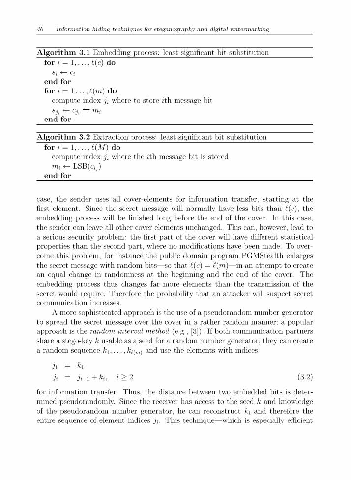
Algorithm 3.1 Embedding process: least significant bit substitution
for i = 1, . . . , `(c) dosi ← ci
end forfor i = 1 . . . , `(m) do
compute index ji where to store ith message bitsji← cji
� mi
end for
Algorithm 3.2 Extraction process: least significant bit substitution
for i = 1, . . . , `(M) docompute index ji where the ith message bit is storedmi ← LSB(cij)
end for
case, the sender uses all cover-elements for information transfer, starting at thefirst element. Since the secret message will normally have less bits than `(c), theembedding process will be finished long before the end of the cover. In this case,the sender can leave all other cover elements unchanged. This can, however, lead toa serious security problem: the first part of the cover will have different statisticalproperties than the second part, where no modifications have been made. To over-come this problem, for instance the public domain program PGMStealth enlargesthe secret message with random bits—so that `(c) = `(m)—in an attempt to createan equal change in randomness at the beginning and the end of the cover. Theembedding process thus changes far more elements than the transmission of thesecret would require. Therefore the probability that an attacker will suspect secretcommunication increases.
A more sophisticated approach is the use of a pseudorandom number generatorto spread the secret message over the cover in a rather random manner; a popularapproach is the random interval method (e.g., [3]). If both communication partnersshare a stego-key k usable as a seed for a random number generator, they can createa random sequence k1, . . . , k`(m) and use the elements with indices
j1 = k1
ji = ji−1 + ki, i ≥ 2 (3.2)
for information transfer. Thus, the distance between two embedded bits is deter-mined pseudorandomly. Since the receiver has access to the seed k and knowledgeof the pseudorandom number generator, he can reconstruct ki and therefore theentire sequence of element indices ji. This technique—which is especially efficient

A survey of steganographic techniques 47
Algorithm 3.3 Embedding process: random interval method
for i = 1 . . . , `(c) dosi ← ci
end forgenerate random sequence ki using seed kn← k1
for i = 1, . . . , `(m) dosn ← cn � mi
n← n + ki
end for
Algorithm 3.4 Extraction process: random interval method
generate random sequence ki using seed kn← k1
for i = 1, . . . , `(m) domi ← LSB(cn)n← n + ki
end for
in the case of stream covers—is illustrated in Algorithms 3.3 and 3.4, which arespecial cases of the general framework presented in Algorithms 3.1 and 3.2.
3.2.2 Pseudorandom permutations
If all cover bits can be accessed in the embedding process (i.e., if c is a randomaccess cover), the secret message bits can be distributed randomly over the wholecover. This technique further increases the complexity for an attacker, since it isnot guaranteed that subsequent message bits are embedded in the same order.
In a first attempt Alice could create (using a pseudorandom number gener-ator) a sequence j1, . . . , j`(m) of element indices and store the kth message bit inthe element with index jk. Note that one index could appear more than once inthe sequence, since we have not restricted the output of the pseudorandom numbergenerator in any way. We call such a case “collision.” If a collision occurs, Alice willpossibly try to insert more than one message bit into one cover-element, therebycorrupting some of them. If the message is quite short compared with the numberof cover-elements, she hopes that the probability of collisions is negligible and thatcorrupted bits could be reconstructed using an error-correcting code. This is, how-
48 Information hiding techniques for steganography and digital watermarking
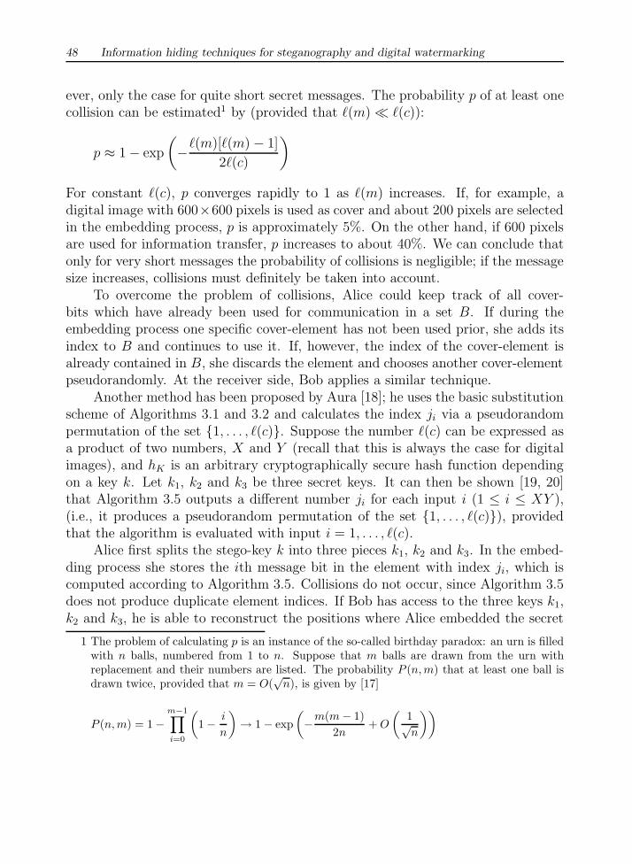
ever, only the case for quite short secret messages. The probability p of at least onecollision can be estimated1 by (provided that `(m)� `(c)):
p ≈ 1− exp
(−`(m)[`(m)− 1]
2`(c)
)
For constant `(c), p converges rapidly to 1 as `(m) increases. If, for example, adigital image with 600×600 pixels is used as cover and about 200 pixels are selectedin the embedding process, p is approximately 5%. On the other hand, if 600 pixelsare used for information transfer, p increases to about 40%. We can conclude thatonly for very short messages the probability of collisions is negligible; if the messagesize increases, collisions must definitely be taken into account.
To overcome the problem of collisions, Alice could keep track of all cover-bits which have already been used for communication in a set B. If during theembedding process one specific cover-element has not been used prior, she adds itsindex to B and continues to use it. If, however, the index of the cover-element isalready contained in B, she discards the element and chooses another cover-elementpseudorandomly. At the receiver side, Bob applies a similar technique.
Another method has been proposed by Aura [18]; he uses the basic substitutionscheme of Algorithms 3.1 and 3.2 and calculates the index ji via a pseudorandompermutation of the set {1, . . . , `(c)}. Suppose the number `(c) can be expressed asa product of two numbers, X and Y (recall that this is always the case for digitalimages), and hK is an arbitrary cryptographically secure hash function dependingon a key k. Let k1, k2 and k3 be three secret keys. It can then be shown [19, 20]that Algorithm 3.5 outputs a different number ji for each input i (1 ≤ i ≤ XY ),(i.e., it produces a pseudorandom permutation of the set {1, . . . , `(c)}), providedthat the algorithm is evaluated with input i = 1, . . . , `(c).
Alice first splits the stego-key k into three pieces k1, k2 and k3. In the embed-ding process she stores the ith message bit in the element with index ji, which iscomputed according to Algorithm 3.5. Collisions do not occur, since Algorithm 3.5does not produce duplicate element indices. If Bob has access to the three keys k1,k2 and k3, he is able to reconstruct the positions where Alice embedded the secret
1 The problem of calculating p is an instance of the so-called birthday paradox: an urn is filledwith n balls, numbered from 1 to n. Suppose that m balls are drawn from the urn withreplacement and their numbers are listed. The probability P (n, m) that at least one ball isdrawn twice, provided that m = O(
√n), is given by [17]
P (n, m) = 1−m−1∏i=0
(1− i
n
)→ 1− exp
(−m(m− 1)
2n+ O
(1√n
))

A survey of steganographic techniques 49
Algorithm 3.5 Computing the index ji using pseudorandom permutations
v ← i div Xu← i modXv ← (v + hk1(u)) modYu← (u + hk2(v)) modXv ← (v + hk3(u)) modYji ← vX + u
message bits. However, Aura’s method needs a considerable amount of computationtime, since the chosen hash function must be evaluated 3`(m) times.
3.2.3 Image downgrading and covert channels
In 1992, Kurak and McHugh [5] reported on a security threat in high-securityoperating systems. Their fear was that a steganographic technique, called imagedowngrading, could be used to exchange images covertly. Image downgrading is aspecial case of a substitution system in which images act both as secret messagesand covers. Given a cover-image and a secret image of equal dimensions, the senderexchanges the four least significant bits of the cover’s grayscale (or color) valueswith the four most significant bits of the secret image. The receiver extracts thefour least significant bits out of the stego-image, thereby gaining access to the mostsignificant bits of the secret image. While the degradation of the cover is not visuallynoticeable in many cases, 4 bits are sufficient to transmit a rough approximation ofthe secret image.
In multilevel-secure operating systems, subjects (processes, users) and objects(files, databases, etc.) are assigned a specific security level; for example, see thefamous Bell-LaPadula [21] model. Subjects are normally only allowed to accessobjects with a lower security level (“no read up”), whereas they are only able to writeonto objects with a higher level (“no write down”). Whereas the reason for the firstrestriction is obvious, the second attempts to prohibit users from making confidentinformation available to subjects with a lower security classification. Informationdowngrading can be used to declassify or downgrade information (hence the name)by embedding classified information into objects with a substantially lower securityclassification and thus subvert the principle of “no write down.” Chapter 4 will lookat possible counterstrategies.
50 Information hiding techniques for steganography and digital watermarking
3.2.4 Cover-regions and parity bits
We will call any nonempty subset of {c1, . . . , c`(c)} a cover-region. By dividing thecover in several disjoint regions, it is possible to store one bit of information in awhole cover-region rather than in a single element. A parity bit of a region I canbe calculated by
p(I) =∑j∈I
LSB(cj) mod 2 (3.3)
In the embedding step, `(m) disjoint cover-regions Ii (1 ≤ i ≤ `(m)) are selected,each encodes one secret bit mi in the parity bit p(Ii). If the parity bit of one cover-region Ii does not match with the secret bit mi to encode, one LSB of the valuesin Ii is flipped. This will result in p(Ii) = mi. In the decoding process, the paritybits of all selected regions are calculated and lined up to reconstruct the message.Again, the cover-regions can be constructed pseudorandomly using the stego-key asa seed.
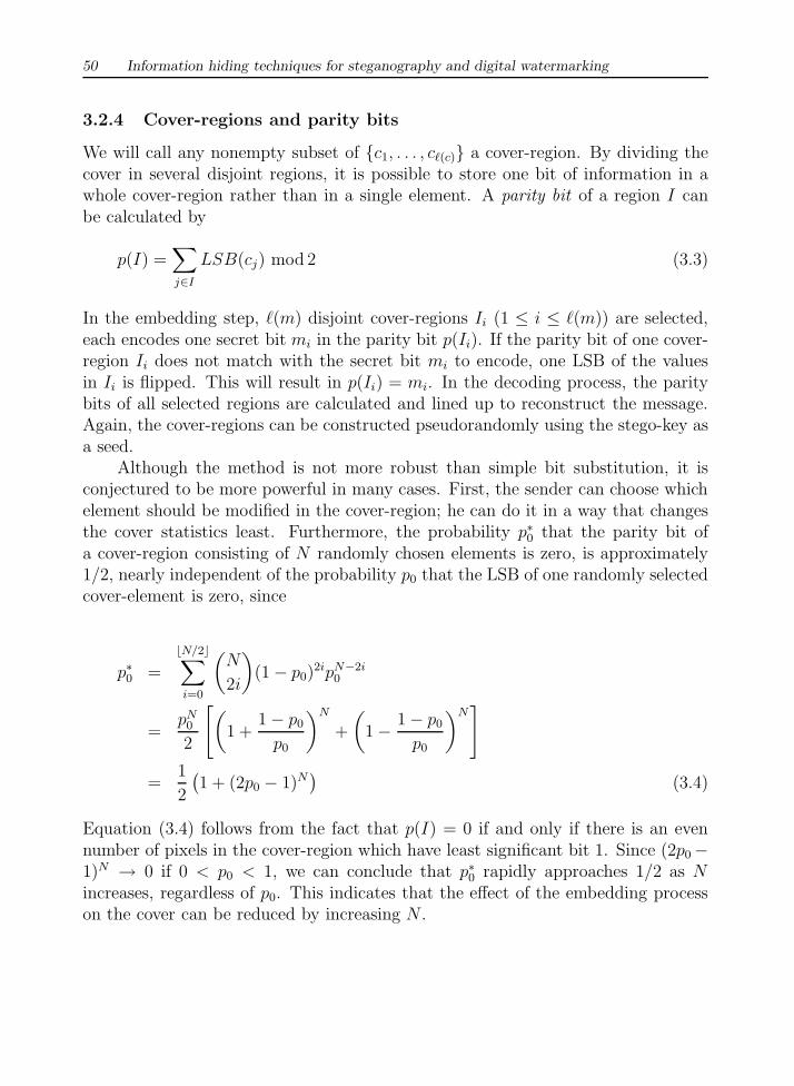
Although the method is not more robust than simple bit substitution, it isconjectured to be more powerful in many cases. First, the sender can choose whichelement should be modified in the cover-region; he can do it in a way that changesthe cover statistics least. Furthermore, the probability p∗0 that the parity bit ofa cover-region consisting of N randomly chosen elements is zero, is approximately1/2, nearly independent of the probability p0 that the LSB of one randomly selectedcover-element is zero, since
p∗0 =
bN/2c∑i=0
(N
2i
)(1− p0)
2ipN−2i0
=pN
0
2
[(1 +
1− p0
p0
)N
+
(1− 1− p0
p0
)N]
=1
2
(1 + (2p0 − 1)N
)(3.4)
Equation (3.4) follows from the fact that p(I) = 0 if and only if there is an evennumber of pixels in the cover-region which have least significant bit 1. Since (2p0−1)N → 0 if 0 < p0 < 1, we can conclude that p∗0 rapidly approaches 1/2 as Nincreases, regardless of p0. This indicates that the effect of the embedding processon the cover can be reduced by increasing N .

A survey of steganographic techniques 51
3.2.5 Palette-based images
In a palette-based image only a subset of colors from a specific color space canbe used to colorize the image. Every palette-based image format consists of twoparts: a palette specifying N colors as a list of indexed pairs (i, ci), assigning a colorvector ci to every index i, and the actual image data which assign a palette indexto every pixel rather than the color value itself. If only a small number of colorvalues are used throughout the image, this approach greatly reduces the file size.Two of the most popular formats are the graphics interchange format (GIF) and theBMP bitmap format. However, due to the availability of sophisticated compressiontechniques, their use declines.
Generally, there are two ways to encode information in a palette-based image:either the palette or the image data can be manipulated. The LSB of the colorvectors could be used for information transfer, just like the substitution methodspresented in the last subsections. Alternatively, since the palette does not need tobe sorted in any way, information can be encoded in the way the colors are storedin the palette. Since there are N ! different ways to sort the palette, there is enoughcapacity to encode a small message. However, all methods which use the order of apalette to store information, are not robust, since an attacker can simply sort theentries in a different way and destroy the secret message (he thereby does not evenmodify the picture visibly).
Alternatively, information can be encoded in the image data. Since neighbor-ing palette color values need not be perceptually similar, the approach of simplychanging the LSB of some image data fails. Some steganographic applications (e.g.,the program EzStego) therefore sort the palette so that neighboring colors are per-ceptually similar before they start the embedding process. Color values can, forinstance, be stored according to their Euclidian distance in RGB space:
d =√
R2 + G2 + B2 (3.5)
Since the human visual system is more sensitive to changes in the luminance ofa color, another (probably better) approach would be sorting the palette entriesaccording to their luminance component, see (3.1). After the palette is sorted, theLSB of color indices can safely be altered.
Fridrich [22] proposes using a slightly different technique which does not needthe palette to be sorted: for every pixel, the set of closest colors (in the Euclidiannorm) is calculated. Starting with the closest color, the sender proceeds to find thenext-closest color until a color is found where its parity (R+G+B mod2) matcheswith the secret bit to encode. Once such a color is found, the pixel is changed tothis new color.
Yet another steganographic application reduces the total number of color values
52 Information hiding techniques for steganography and digital watermarking
in a picture to bN/2c using some dithering method, and doubles the entire palette;thereby all doubled entries are slightly modified. After this preprocessing stage,each color value of the dithered image corresponds to two palette entries, from whichone is chosen according to a secret message bit (e.g., Mandelsteg [11], S-Tools [10],Hide4PGP [14], and Hide and Seek [13] apply variations of this method).
3.2.6 Quantization and dithering
Dithering and quantization of digital images can be used for embedding secret in-formation. Matsui and Tanaka [23] presented two steganographic systems whichoperate on quantized images. We briefly review quantization in the context of pre-dictive coding here. In predictive coding, the intensity of each pixel is predictedbased on the pixel values in a specific neighborhood; the prediction may be a lin-ear or nonlinear function of the surrounding pixel values. In its simplest form, thedifference ei between adjacent pixels xi and xi+1 is calculated and fed into a quan-tizer Q which outputs a discrete approximation ∆i of the difference signal xi−xi−1
(i.e., ∆i = Q(xi − xi−1)). Thus, in each quantization step a quantization erroris introduced. For highly correlated signals we can expect ∆i to be close to zero,so an entropy coder—which tries to create a minimum-redundancy code given astochastic model of the data to be transmitted—will be efficient. At the receiverside the difference signal is dequantized and added to the last signal sample in orderto construct an estimate for the sequence xi.
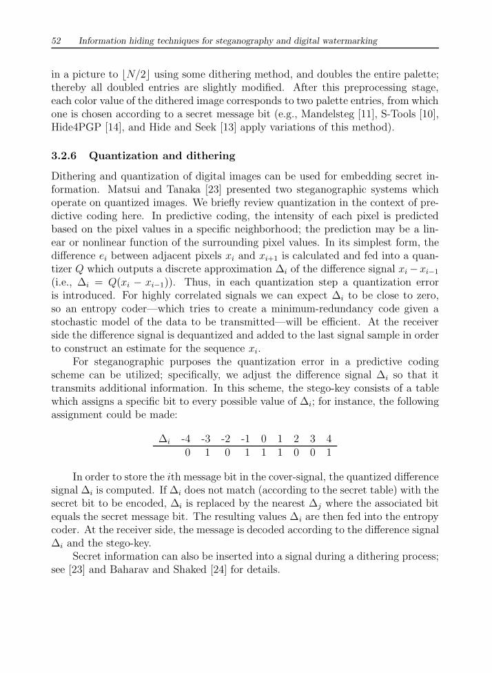
For steganographic purposes the quantization error in a predictive codingscheme can be utilized; specifically, we adjust the difference signal ∆i so that ittransmits additional information. In this scheme, the stego-key consists of a tablewhich assigns a specific bit to every possible value of ∆i; for instance, the followingassignment could be made:
∆i -4 -3 -2 -1 0 1 2 3 40 1 0 1 1 1 0 0 1
In order to store the ith message bit in the cover-signal, the quantized differencesignal ∆i is computed. If ∆i does not match (according to the secret table) with thesecret bit to be encoded, ∆i is replaced by the nearest ∆j where the associated bitequals the secret message bit. The resulting values ∆i are then fed into the entropycoder. At the receiver side, the message is decoded according to the difference signal∆i and the stego-key.
Secret information can also be inserted into a signal during a dithering process;see [23] and Baharav and Shaked [24] for details.
A survey of steganographic techniques 53
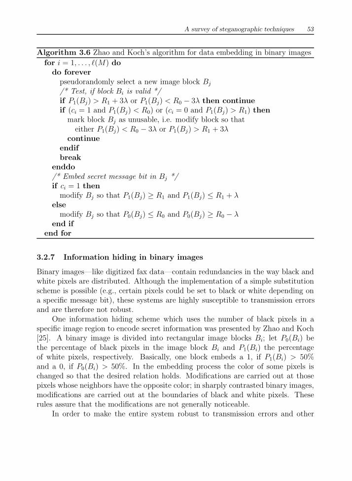
Algorithm 3.6 Zhao and Koch’s algorithm for data embedding in binary images
for i = 1, . . . , `(M) dodo forever
pseudorandomly select a new image block Bj
/* Test, if block Bi is valid */if P1(Bj) > R1 + 3λ or P1(Bj) < R0 − 3λ then continueif (ci = 1 and P1(Bj) < R0) or (ci = 0 and P1(Bj) > R1) then
mark block Bj as unusable, i.e. modify block so thateither P1(Bj) < R0 − 3λ or P1(Bj) > R1 + 3λ
continueendifbreak
enddo/* Embed secret message bit in Bj */if ci = 1 then
modify Bj so that P1(Bj) ≥ R1 and P1(Bj) ≤ R1 + λelse
modify Bj so that P0(Bj) ≤ R0 and P0(Bj) ≥ R0 − λend if
end for
3.2.7 Information hiding in binary images
Binary images—like digitized fax data—contain redundancies in the way black andwhite pixels are distributed. Although the implementation of a simple substitutionscheme is possible (e.g., certain pixels could be set to black or white depending ona specific message bit), these systems are highly susceptible to transmission errorsand are therefore not robust.
One information hiding scheme which uses the number of black pixels in aspecific image region to encode secret information was presented by Zhao and Koch[25]. A binary image is divided into rectangular image blocks Bi; let P0(Bi) bethe percentage of black pixels in the image block Bi and P1(Bi) the percentageof white pixels, respectively. Basically, one block embeds a 1, if P1(Bi) > 50%and a 0, if P0(Bi) > 50%. In the embedding process the color of some pixels ischanged so that the desired relation holds. Modifications are carried out at thosepixels whose neighbors have the opposite color; in sharply contrasted binary images,modifications are carried out at the boundaries of black and white pixels. Theserules assure that the modifications are not generally noticeable.
In order to make the entire system robust to transmission errors and other
54 Information hiding techniques for steganography and digital watermarking
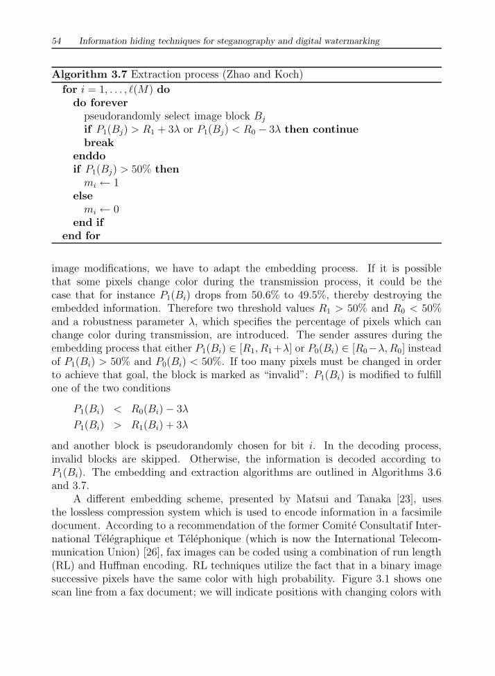
Algorithm 3.7 Extraction process (Zhao and Koch)
for i = 1, . . . , `(M) dodo forever
pseudorandomly select image block Bj
if P1(Bj) > R1 + 3λ or P1(Bj) < R0 − 3λ then continuebreak
enddoif P1(Bj) > 50% then
mi ← 1else
mi ← 0end if
end for
image modifications, we have to adapt the embedding process. If it is possiblethat some pixels change color during the transmission process, it could be thecase that for instance P1(Bi) drops from 50.6% to 49.5%, thereby destroying theembedded information. Therefore two threshold values R1 > 50% and R0 < 50%and a robustness parameter λ, which specifies the percentage of pixels which canchange color during transmission, are introduced. The sender assures during theembedding process that either P1(Bi) ∈ [R1, R1+λ] or P0(Bi) ∈ [R0−λ, R0] insteadof P1(Bi) > 50% and P0(Bi) < 50%. If too many pixels must be changed in orderto achieve that goal, the block is marked as “invalid”: P1(Bi) is modified to fulfillone of the two conditions
P1(Bi) < R0(Bi)− 3λ
P1(Bi) > R1(Bi) + 3λ
and another block is pseudorandomly chosen for bit i. In the decoding process,invalid blocks are skipped. Otherwise, the information is decoded according toP1(Bi). The embedding and extraction algorithms are outlined in Algorithms 3.6and 3.7.
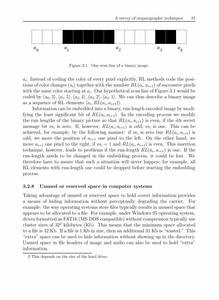
A different embedding scheme, presented by Matsui and Tanaka [23], usesthe lossless compression system which is used to encode information in a facsimiledocument. According to a recommendation of the former Comite Consultatif Inter-national Telegraphique et Telephonique (which is now the International Telecom-munication Union) [26], fax images can be coded using a combination of run length(RL) and Huffman encoding. RL techniques utilize the fact that in a binary imagesuccessive pixels have the same color with high probability. Figure 3.1 shows onescan line from a fax document; we will indicate positions with changing colors with
A survey of steganographic techniques 55
a a a a a2 4310
Figure 3.1 One scan line of a binary image.
ai. Instead of coding the color of every pixel explicitly, RL methods code the posi-tions of color changes (ai) together with the number RL(ai, ai+1) of successive pixelswith the same color starting at ai. Our hypothetical scan line of Figure 3.1 would becoded by 〈a0, 3〉, 〈a1, 5〉, 〈a2, 4〉, 〈a3, 2〉, 〈a4, 1〉. We can thus describe a binary imageas a sequence of RL elements 〈ai, RL(ai, ai+1)〉.
Information can be embedded into a binary, run-length encoded image by modi-fying the least significant bit of RL(ai, ai+1). In the encoding process we modifythe run lengths of the binary picture so that RL(ai, ai+1) is even, if the ith secretmessage bit mi is zero. If, however, RL(ai, ai+1) is odd, mi is one. This can beachieved, for example, by the following manner: if mi is zero but RL(ai, ai+1) isodd, we move the position of ai+1 one pixel to the left. On the other hand, wemove ai+1 one pixel to the right, if mi = 1 and RL(ai, ai+1) is even. This insertiontechnique, however, leads to problems if the run-length RL(ai, ai+1) is one. If therun-length needs to be changed in the embedding process, it could be lost. Wetherefore have to assure that such a situation will never happen; for example, allRL elements with run-length one could be dropped before starting the embeddingprocess.
3.2.8 Unused or reserved space in computer systems
Taking advantage of unused or reserved space to hold covert information providesa means of hiding information without perceptually degrading the carrier. Forexample: the way operating systems store files typically results in unused space thatappears to be allocated to a file. For example, under Windows 95 operating system,drives formatted as FAT16 (MS-DOS compatible) without compression typically usecluster sizes of 322 kilobytes (Kb). This means that the minimum space allocatedto a file is 32 Kb. If a file is 1 Kb in size, then an additional 31 Kb is “wasted.” This“extra” space can be used to hide information without showing up in the directory.Unused space in file headers of image and audio can also be used to hold “extra”information.
2 This depends on the size of the hard drive.
56 Information hiding techniques for steganography and digital watermarking
Another method of hiding information in file systems is to create a hiddenpartition. These partitions are not seen if the system is started normally. However,in many cases, running a disk configuration utility (such as DOS’s FDISK) exposesthe hidden partition. These concepts have been expanded in a novel proposal of asteganographic file system [27, 28]. If the user knows the file name and password,access is granted to the file; otherwise, no evidence of the file exists in the system.
Protocols in the OSI network model have characteristics that can be used tohide information [29]. TCP/IP packets used to transport information across theInternet have unused space in the packet headers. The TCP packet header has sixunused (reserved) bits and the IP packet header has two reserved bits. Thousandsof packets are transmitted with each communication channel, which provides an ex-cellent covert communication channel if unchecked. The ease in use and abundantavailability of steganography tools has law enforcement concerned in trafficking of il-licit material via Web page images, audio, and other files being transmitted throughthe Internet. Methods of message detection and understanding the thresholds ofcurrent technology are necessary to uncover such activities (see Chapter 4).
3.3 TRANSFORM DOMAIN TECHNIQUES
We have seen that LSB modification techniques are easy ways to embed information,but they are highly vulnerable to even small cover modifications. An attacker cansimply apply signal processing techniques in order to destroy the secret informationentirely. In many cases even the small changes resulting out of lossy compressionsystems yield to total information loss.
It has been noted early in the development of steganographic systems thatembedding information in the frequency domain of a signal can be much more robustthan embedding rules operating in the time domain. Most robust steganographicsystems known today actually operate in some sort of transform domain.
Transform domain methods hide messages in significant areas of the cover imagewhich makes them more robust to attacks, such as compression, cropping, andsome image processing, than the LSB approach. However, while they are morerobust to various kinds of signal processing, they remain imperceptible to the humansensory system. Many transform domain variations exist. One method is to use thediscrete cosine transformation (DCT) [30–33] as a vehicle to embed information inimages; another would be the use of wavelet transforms [34]. Transformations can beapplied over the entire image [30], to blocks throughout the image [35, 36], or othervariations. However, a trade-off exists between the amount of information added tothe image and the robustness obtained [7, 37]. Many transform domain methods

A survey of steganographic techniques 57
are independent to image format and may survive conversion between lossless andlossy formats.
Before we describe transform domain steganographic methods, we will brieflyreview the Fourier and cosine transforms which can be used to map a signal intothe frequency domain. The discrete Fourier transform (DFT) of a sequence s oflength N is defined to be
S(k) = F{s} =
N−1∑n=0
s(n) exp
(−2inπk
N
)(3.6)
where i =√−1 is the imaginary unit. The inverse Fourier transform is given by
s(k) = F−1{S} =N−1∑n=0
S(n) exp
(2inπk
N
)(3.7)
Another useful transform is the DCT, given by
S(k) = D{s} =C(k)
2
N∑j=0
s(j) cos
((2j + 1)kπ
2N
)
s(k) = D−1{S} =N∑
j=0
C(j)
2s(j) cos
((2j + 1)kπ
2N
)(3.8)
where C(u) = 1/√
2 if u = 0 and C(u) = 1 otherwise. The DCT has the primaryadvantage that D{s} is a sequence of real numbers, provided that the sequence s isreal. In digital image processing, the two-dimensional version of the DCT is used:
S(u, v) =2
NC(u)C(v)
N−1∑x=0
N−1∑y=0
s(x, y) cos
(πu(2x + 1)
2N
)cos
(πv(2y + 1)
2N
)
s(x, y) =2
N
N−1∑u=0
N−1∑v=0
C(u)C(v)S(u, v) cos
(πu(2x + 1)
2N
)cos
(πv(2y + 1)
2N
)
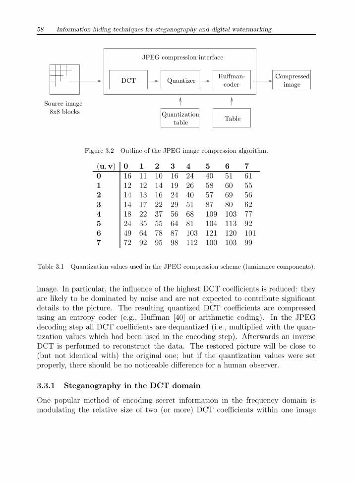
The two-dimensional DCT is the “heart” of the most popular lossy digital imagecompression system used today: the JPEG system [38, 39] (see Figure 3.2). JPEGfirst converts the image to be compressed into the YCbCr color space and breaks upeach color plane into 8×8 blocks of pixels. Then, all blocks are DCT transformed.In a quantization step all DCT coefficients are divided by some predefined quan-tization values (see Table 3.1) and rounded to the nearest integer (according to aquality factor, the quantization values can be scaled by a constant). The purpose ofthis process is to modulate the influence of the different spectral components on the
58 Information hiding techniques for steganography and digital watermarking
Source image8x8 blocks
JPEG compression interface
DCT QuantizerHuffman-
coder
Quantizationtable Table
Compressedimage
Figure 3.2 Outline of the JPEG image compression algorithm.
(u,v) 0 1 2 3 4 5 6 70 16 11 10 16 24 40 51 611 12 12 14 19 26 58 60 552 14 13 16 24 40 57 69 563 14 17 22 29 51 87 80 624 18 22 37 56 68 109 103 775 24 35 55 64 81 104 113 926 49 64 78 87 103 121 120 1017 72 92 95 98 112 100 103 99
Table 3.1 Quantization values used in the JPEG compression scheme (luminance components).
image. In particular, the influence of the highest DCT coefficients is reduced: theyare likely to be dominated by noise and are not expected to contribute significantdetails to the picture. The resulting quantized DCT coefficients are compressedusing an entropy coder (e.g., Huffman [40] or arithmetic coding). In the JPEGdecoding step all DCT coefficients are dequantized (i.e., multiplied with the quan-tization values which had been used in the encoding step). Afterwards an inverseDCT is performed to reconstruct the data. The restored picture will be close to(but not identical with) the original one; but if the quantization values were setproperly, there should be no noticeable difference for a human observer.
3.3.1 Steganography in the DCT domain
One popular method of encoding secret information in the frequency domain ismodulating the relative size of two (or more) DCT coefficients within one image

A survey of steganographic techniques 59
Algorithm 3.8 DCT–Steg encoding process
for i = 1, . . . , `(M) dochoose one cover-block bi
Bi = D{bi}if mi = 0 then
if Bi(u1, v1) > Bi(u2, v2) thenswap Bi(u1, v1) and Bi(u2, v2)
end ifelse
if Bi(u1, v1) < Bi(u2, v2) thenswap Bi(u1, v1) and Bi(u2, v2)
end ifend ifadjust both values so that |Bi(u1, v1)− Bi(u2, v2)| > xb′i = D−1{Bi}
end forcreate stego-image out of all b′i
block. We will describe a system which uses digital images as covers and which issimilar to a technique proposed by Zhao and Koch [25].
During the encoding process, the sender splits the cover-image in 8×8 pixelblocks; each block encodes exactly one secret message bit. The embedding processstarts with selecting a pseudorandom block bi which will be used to code the ithmessage bit. Let Bi = D{bi} be the DCT-transformed image block.
Before the communication starts, both sender and receiver have to agree onthe location of two DCT coefficients, which will be used in the embedding process;let us denote these two indices by (u1, v1) and (u2, v2). The two coefficients shouldcorrespond to cosine functions with middle frequencies; this ensures that the infor-mation is stored in significant parts of the signal (hence the embedded informationwill not be completely damaged by JPEG compression). Furthermore, we can as-sume that the embedding process will not degenerate the cover heavily, because it iswidely believed that DCT coefficients of middle frequencies have similar magnitudes[41]. Since the constructed system should be robust against JPEG compression, wechoose the DCT coefficients in such a way that the quantization values associatedwith them in the JPEG compression algorithm are equal. According to Table 3.1the coefficients (4,1) and (3,2) or (1,2) and (3,0) are good candidates.
One block encodes a “1,” if Bi(u1, v1) > Bi(u2, v2), otherwise a “0.” In theencoding step, the two coefficients are swapped if their relative size does not matchwith the bit to be encoded. Since the JPEG compression can (in the quantiza-
60 Information hiding techniques for steganography and digital watermarking
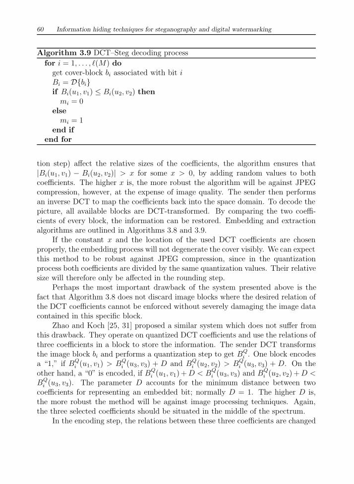
Algorithm 3.9 DCT–Steg decoding process
for i = 1, . . . , `(M) doget cover-block bi associated with bit iBi = D{bi}if Bi(u1, v1) ≤ Bi(u2, v2) then
mi = 0else
mi = 1end if
end for
tion step) affect the relative sizes of the coefficients, the algorithm ensures that|Bi(u1, v1) − Bi(u2, v2)| > x for some x > 0, by adding random values to bothcoefficients. The higher x is, the more robust the algorithm will be against JPEGcompression, however, at the expense of image quality. The sender then performsan inverse DCT to map the coefficients back into the space domain. To decode thepicture, all available blocks are DCT-transformed. By comparing the two coeffi-cients of every block, the information can be restored. Embedding and extractionalgorithms are outlined in Algorithms 3.8 and 3.9.
If the constant x and the location of the used DCT coefficients are chosenproperly, the embedding process will not degenerate the cover visibly. We can expectthis method to be robust against JPEG compression, since in the quantizationprocess both coefficients are divided by the same quantization values. Their relativesize will therefore only be affected in the rounding step.
Perhaps the most important drawback of the system presented above is thefact that Algorithm 3.8 does not discard image blocks where the desired relation ofthe DCT coefficients cannot be enforced without severely damaging the image datacontained in this specific block.
Zhao and Koch [25, 31] proposed a similar system which does not suffer fromthis drawback. They operate on quantized DCT coefficients and use the relations ofthree coefficients in a block to store the information. The sender DCT transformsthe image block bi and performs a quantization step to get BQ
i . One block encodesa “1,” if BQ
i (u1, v1) > BQi (u3, v3) + D and BQ
i (u2, v2) > BQi (u3, v3) + D. On the
other hand, a “0” is encoded, if BQi (u1, v1) + D < BQ
i (u3, v3) and BQi (u2, v2) + D <
BQi (u3, v3). The parameter D accounts for the minimum distance between two
coefficients for representing an embedded bit; normally D = 1. The higher D is,the more robust the method will be against image processing techniques. Again,the three selected coefficients should be situated in the middle of the spectrum.
In the encoding step, the relations between these three coefficients are changed
A survey of steganographic techniques 61
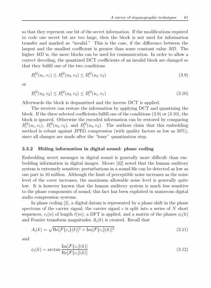
so that they represent one bit of the secret information. If the modifications requiredto code one secret bit are too large, then the block is not used for informationtransfer and marked as “invalid.” This is the case, if the difference between thelargest and the smallest coefficient is greater than some constant value MD . Thehigher MD is, the more blocks can be used for communication. In order to allow acorrect decoding, the quantized DCT coefficients of an invalid block are changed sothat they fulfill one of the two conditions
BQi (u1, v1) ≤ BQ
i (u3, v3) ≤ BQi (u2, v2) (3.9)
or
BQi (u2, v2) ≤ BQ
i (u3, v3) ≤ BQi (u1, v1) (3.10)
Afterwards the block is dequantized and the inverse DCT is applied.The receiver can restore the information by applying DCT and quantizing the
block. If the three selected coefficients fulfill one of the conditions (3.9) or (3.10), theblock is ignored. Otherwise the encoded information can be restored by comparingBQ
i (u1, v1), BQi (u2, v2), and BQ
i (u3, v3). The authors claim that this embeddingmethod is robust against JPEG compression (with quality factors as low as 50%),since all changes are made after the “lossy” quantization step.
3.3.2 Hiding information in digital sound: phase coding
Embedding secret messages in digital sound is generally more difficult than em-bedding information in digital images. Moore [42] noted that the human auditorysystem is extremely sensitive; perturbations in a sound file can be detected as low asone part in 10 million. Although the limit of perceptible noise increases as the noiselevel of the cover increases, the maximum allowable noise level is generally quitelow. It is however known that the human auditory system is much less sensitiveto the phase components of sound; this fact has been exploited in numerous digitalaudio compression systems.
In phase coding [2], a digital datum is represented by a phase shift in the phasespectrum of the carrier signal; the carrier signal c is split into a series of N shortsequences, ci(n) of length `(m), a DFT is applied, and a matrix of the phases φi(k)and Fourier transform magnitudes Ai(k) is created. Recall that
Ai(k) =√
Re[F{ci}(k)]2 + Im[F{ci}(k)]2 (3.11)
and
φi(k) = arctanIm[F{ci}(k)]
Re[F{ci}(k)](3.12)

62 Information hiding techniques for steganography and digital watermarking
Since phase shifts between consecutive signal segments can easily be detected, theirphase differences need to be preserved in the stego-signal. The embedding processthus inserts a secret message only in the phase vector of the first signal segment:
φ0(k) =
{π/2 if mk = 0−π/2 if mk = 1
(3.13)
and creates a new phase matrix using the original phase differences
φ1(k) = φ0(k) + [φ1(k)− φ0(k)]
. . .
φN(k) = φN−1(k) + [φN(k)− φN−1(k)] (3.14)
The sender then uses the new phase matrix φi(k) and the original matrix of Fouriertransform magnitudes Ai(k) to construct the stego-signal using the inverse Fouriertransform. Since φ0(k) is modified, the absolute phases of all following segments arechanged, while their relative differences are preserved. Before the secret informationcan be restored, some sort of synchronization must take place. Given the knowledgeof the sequence length `(m), the receiver is able to calculate the DFT and to detectthe phases φ0(k).
3.3.3 Echo hiding
Echo hiding [4] attempts to hide information in a discrete signal f(t) by introducingan echo f(t−∆t) in the stego-signal c(t):
c(t) = f(t) + αf(t−∆t) (3.15)
Information is encoded in the signal by modifying the delay ∆t between the signaland the echo. In the encoding step, the sender chooses either ∆t or ∆t′; in the firstcase, a “0” is encoded in the signal c(t), in the latter case a “1.” The delay times ∆tor ∆t′ are chosen in a way that the echo signal is not audible for a human observer.
The basic echo hiding scheme can only embed one bit in a signal; therefore acover signal is divided into `(m) blocks prior to the encoding process. Consecutiveblocks should be separated by a random number of unused samples so that thedetection and extraction of the secret message bits is harder. In each block onesecret bit is embedded according to (3.15); in the last step all signal blocks areconcatenated.
Before the secret message can be extracted out of the stego-signal, some sortof synchronization must take place; the receiver must be able to reconstruct the`(m) signal blocks the sender used to embed one secret message bit. Each signal
A survey of steganographic techniques 63
segment can then be decoded via the autocorrelation function of the signal’s cep-strum. Gruhl et al. [4] show that the autocorrelation function shows a spike at thedelay time ∆t. For a further investigation of echo hiding see Section 7.5.1.
Chang and Moskowitz [43] analyze several methods usable for information hid-ing in digital sound, among them low-bit coding (LSB), phase coding, spread spec-trum techniques (see Section 3.4), and echo hiding. Low-bit coding techniques arenot robust, but have the highest data transmission rate. Phase coding providesrobustness against resampling of the carrier signal, but has a very low data trans-mission rate since secret information is encoded only in the first signal segment. Onthe contrary, spread spectrum and echo hiding perform better in many cases.
3.3.4 Information hiding and data compression
In some cases, information hiding algorithms are incorporated in data compressionsystems; one can think of a videoconferencing system which allows messages to behidden in the video stream while it is being recorded. Most research work focussedon information hiding schemes for lossy video or image compression systems, butit should be noted that lossless compression systems can also be used for secret in-formation transfer; Cachin [44] showed how to construct an asymptotically optimalsteganographic system by modifying Willems [45] “repetition times” compressionalgorithm.
Numerous steganographic systems for compressed video or images have beenproposed. In the simplest technique, applied by the tool Jpeg-Jsteg [46], informa-tion is hidden in the way DCT coefficients in the JPEG compression system (seeSection 3.3) are rounded. Since the DCT normally outputs noninteger sequences forinteger inputs, the JPEG system must quantize DCT coefficients before the encod-ing process. Information is hidden by rounding the coefficients either up or downaccording to the secret message bits. Although such a system is not robust, detec-tion of the cover modifications seems to be difficult. Westfeld and Wolf [47] describea similar technique. Their system operates on quantized, DCT-encoded blocks ofvideo frames. After distinguishing blocks which are suitable for secret transmissionfrom unusable blocks, the modulo-2 sum of the DCT coefficients of the block ischanged in a way that it transmits secret information (see [47] for details). Moresophisticated methods combine video compression schemes with spread spectrum.As an example, Hartung and Girod [48, 49] presented an information-hiding schemeoperating on precompressed video using their spread spectrum watermarking system(see Section 6.4.1).

64 Information hiding techniques for steganography and digital watermarking
3.4 SPREAD SPECTRUM AND INFORMATION HIDING
Spread spectrum (SS) communication technologies have been developed since the1950s in an attempt to provide means of low-probability-of-intercept and antijam-ming communications. Pickholtz et al. [50] define spread spectrum techniques as“means of transmission in which the signal occupies a bandwidth in excess of theminimum necessary to send the information; the band spread is accomplished bymeans of a code which is independent of the data, and a synchronized reception withthe code at the receiver is used for despreading and subsequent data recovery.” Al-though the power of the signal to be transmitted can be large, the signal-to-noiseratio in every frequency band will be small. Even if parts of the signal could beremoved in several frequency bands, enough information should be present in theother bands to recover the signal. Thus, SS makes it difficult to detect and/or re-move a signal. This situation is very similar to a steganography system which triesto spread a secret message over a cover in order to make it impossible to perceive.Since spreaded signals tend to be difficult to remove, embedding methods based onSS should provide a considerable level of robustness. Since the landmark paper byTirkel et al. [51], spread spectrum methods are of increasing importance in the fieldof information hiding.
In information hiding, two special variants of SS are generally used: direct-sequence and frequency-hopping schemes. In direct-sequence schemes, the secretsignal is spread by a constant called chip rate, modulated with a pseudorandomsignal and added to the cover. On the other hand, in frequency-hopping schemesthe frequency of the carrier signal is altered in a way that it hops rapidly from onefrequency to the another. SS are widely used in the context of watermarking, aswill be shown in Section 6.4.1. One particularly interesting direct-sequence water-marking algorithm, invented by Hartung and Girod [48, 49], which could also beused for steganographic purposes, will be described in Section 6.4.1.
Due to the similarity of SS watermarking and steganography algorithms, we willlimit the discussion in this chapter to presenting a mathematical model describingthe application of spread spectrum techniques in information hiding and discuss asystem called SSIS as a case study.
3.4.1 A spread spectrum model
Smith and Comiskey [52] presented a general framework for spread spectrumsteganography. Their approach originally used N × M grayscale images as cov-ers; however, the work can easily be extended to all cover sets on which a scalarproduct can be defined. We will assume that Alice and Bob share a set of (at

A survey of steganographic techniques 65
least) `(m) orthogonal N × M images φi as a stego-key. Alice first generates astego-message E(x, y) by building the weighted sum
E(x, y) =∑
i
miφi(x, y) (3.16)
The images φi are orthogonal to each other,
〈φi, φj〉 =
N∑x=1
M∑y=1
φi(x, y)φj(x, y) = Giδi,j (3.17)
where Gi =∑N
x=1
∑My=1 φ2
i (x, y) and δi,j is the Kronecker delta function. Alice thenencodes the secret information E in a cover C by building the element-wise sum ofboth images, creating the stego-cover S:
S(x, y) = C(x, y) + E(x, y) (3.18)
In the ideal case, C is orthogonal to all φi, (so 〈C, φi〉 = 0) and Bob can extractthe ith message bit mi by projecting the stego-image S onto the ith basis image φi:
〈S, φi〉 = 〈C, φi〉+⟨∑
j
mjφj, φi
⟩
=∑
j
mj 〈φj, φi〉
= Gimi (3.19)
Therefore, the secret information can be recovered by calculating mi = 〈S, φi〉 /Gi.Note that the original cover C is not needed in the decoding phase. In practice,however, C will not be completely orthogonal to all images φi, so an error term〈C, φi〉 = ∆Ci has to be introduced in (3.19):
〈S, φi〉 = ∆Ci + Gimi (3.20)
We will now show that under reasonable assumptions the expected value of ∆Ci
is zero. Let both C and φi be two independent NM-dimensional random variables.If we assume that all basis images were created using a zero-mean random processand they are independent from the messages to be transmitted, then
E[∆Ci] =
N∑i=1
M∑j=1
E[C(x, y)]E[φi(x, y)] = 0 (3.21)
Thus, the expected value of the error term in (3.20) is zero under these assumptions.

66 Information hiding techniques for steganography and digital watermarking
The decoding operation therefore consists of reconstructing a secret message byprojecting the stego-image S onto all functions φi yielding an approximative value
si = 〈S, φi〉 = ∆Ci + Gimi (3.22)
Subject to the conditions stated above, the expected value of ∆Ci is zero, so si ≈Gimi. The final task is to reconstruct mi from si. If we encode secret messages asstrings of −1 and 1 instead of simply using binary strings, the values of mi can bereconstructed using the sign function, provided that Gi � 0:
mi = sign(si) =
−1 if si < 00 if si = 01 if si > 0
(3.23)
In the case of mi = 0 the encoded information has been lost. In some severe circum-stances the quantity |∆Ci| could become so large (recall that we have only provedthat the expected value is zero) that the recovery of one bit is not possible. How-ever, this case will not happen often and can be coped with by the implementationof an error-correcting code.
The main advantage of using spread spectrum techniques in steganographyis the relative robustness to image modifications. Since the encoded informationis spread over a wide frequency band it is quite difficult to remove it completelywithout entirely destroying the cover. In practice, modifications of the stego-coverwill increase the value of ∆Ci. These modifications will not be harmful to theembedded message, unless |∆Ci| > |Gimi|.
3.4.2 SSIS: a case study
Marvel et al. [53] presented a steganographic system called SSIS which we willdiscuss here briefly as a case study. SSIS uses a spread spectrum technique asan embedding function; this mechanism can be described as follows. Before theembedding process, the secret message is encrypted using a conventional symmet-ric encryption scheme, thereby using a secret key k1. Furthermore, the encryptedsecret message will be encoded via a low-rate error-correcting code (such as a Reed-Solomon code). This step will increase the robustness of the overall steganographicapplication. The resulting encoded message is then modulated by a pseudoran-dom sequence produced by a pseudorandom number generator using k2 as seed.The resulting (random-looking) signal is then input into an interleaver (which usesk3 as seed) and added to the cover. In a last step, the resulting stego-image isappropriately quantized.
At the receiver side the embedding process is reversed. Since one design goalof SSIS was to provide a blind steganographic system—thus, a system in which

A survey of steganographic techniques 67
the original image is not needed in the decoding process—an estimate of the orig-inal image is obtained using an image-restoration technique such as an adaptiveWiener filter. Subtracting the stego-image from the cover-image estimate yields anestimate for the modulated and spread stego-message. The resulting bits are thendeinterleaved and demodulated (using k3 and k2). Due to the poor performanceof the Wiener filter, the reconstructed secret message will contain incorrect bits;the stego-system can thus be seen as a form of transmission on a noisy channel.However, the use of an error-correcting code can help to recover corrupted messagebits. In a last step, the secret message is decrypted.
3.5 STATISTICAL STEGANOGRAPHY
Statistical steganography techniques utilize the existence of “1-bit” steganographicschemes, which embed one bit of information in a digital carrier. This is doneby modifying the cover in such a way that some statistical characteristics changesignificantly if a “1” is transmitted. Otherwise the cover is left unchanged. So thereceiver must be able to distinguish unmodified covers from modified ones.
In order to construct a `(m)-bit stego-system from multiple “1-bit” stego-systems, a cover is divided into `(m) disjoint blocks B1, . . . , B`(m). A secret bit,mi, is inserted into the ith block by placing a “1” into Bi if mi = 1. Otherwise,the block is not changed in the embedding process. The detection of a specific bitis done via a test function which distinguishes modified blocks from unmodifiedblocks:
f(Bi) =
{1 block Bi was modified in the embedding process0 otherwise
(3.24)
The function f can be interpreted as a hypothesis-testing function; we test the null-hypothesis “block Bi was not modified” against the alternative hypothesis “blockBi was modified.” Therefore, we call the whole class of such steganography systemsstatistical steganography. The receiver successively applies f to all cover-blocks Bi
in order to restore every bit of the secret message.The main question which remains to be solved is how such a function f in (3.24)
can be constructed. If we interpret f as a hypothesis-testing function, we can usethe theory of hypothesis testing from mathematical statistics. Let us assume wecan find a formula h(Bi), which depends on some elements of the cover-block Bi,and we know the distribution of h(Bi) in the unmodified block (i.e., the hypothesisholds in this case). We can then use standard procedures to test if h(Bi) equals orexceeds a specific value. If we manage to alter h(Bi) in the embedding process in away that its expected value is 0 if the block Bi was not modified, and its expected
68 Information hiding techniques for steganography and digital watermarking
value is much greater otherwise, we could test whether h(Bi) equals zero under thegiven distribution of h(Bi).
Statistical steganographic techniques are, however, difficult to apply in manycases. First, a good test statistic h(Bi) must be found which allows distinctionbetween modified and unmodified cover-blocks. Additionally, the distribution ofh(Bi) must be known for a “normal” cover; in most cases, this is quite a difficulttask. In practical implementations many (quite questionable) assumptions are madein order to determine a closed formula for this distribution.
As an example, we want to construct a statistical steganography algorithm outof Pitas’ watermarking system [54], which is similar to the Patchwork approach of
Bender et al. [2]. Suppose every cover-block Bi is a rectangular set of pixels p(i)n,m.
Furthermore, let S = {s(i)n,m} be a rectangular pseudorandom binary pattern of equal
size, where the number of ones in S equals the number of zeros. We will assumethat both the sender and receiver have access to S, which represents the stego-keyin this application. The sender first splits the image block Bi into two sets, Ci andDi, of equal size (i.e., he puts all pixels with indices (n, m) into set C where thecorresponding key bit sn,m equals zero):
Ci = {p(i)n,m ∈ Bi|sn,m = 1}
Di = {p(i)n,m ∈ Bi|sn,m = 0} (3.25)
The sender then adds a value k > 0 to all pixels in the subset Ci but leaves allpixels in Di unchanged. In the last step, Ci and Di are merged to form the markedimage block Bi.
In order to extract the mark, the receiver reconstructs the sets Ci and Di. Ifthe block contains a mark, all values in Ci will be larger than the correspondingvalues in the embedding step; thus we test the difference of the means of sets Ci
and Di. If we assume that all pixels in both Ci and Di are independent identicallydistributed random variables with an arbitrary distribution, the test statistic
qi =Ci −Di
σi(3.26)
with
σi =
√Var[Ci] + Var[Di]
|S|/2(3.27)
where Ci denotes the mean over all pixels in the set Ci and Var[Ci] the estimatedvariance of the random variables in Ci, will follow a N(0, 1) normal distributionasymptotically due to the central limit theorem. If a mark is embedded in the
A survey of steganographic techniques 69
image block Bi, the expected value of q will be greater than zero. The receiver isthus able to reconstruct the ith secret message bit by testing whether the statisticqi of block Bi equals zero under the N(0, 1) distribution.
3.6 DISTORTION TECHNIQUES
In contrast to substitution systems, distortion techniques require the knowledge ofthe original cover in the decoding process. Alice applies a sequence of modificationsto a cover in order to get a stego-object; she chooses this sequence of modificationsin such a way that it corresponds to a specific secret message she wants to trans-mit. Bob measures the differences to the original cover in order to reconstruct thesequence of modifications applied by Alice, which corresponds to the secret message.
In many applications, such systems are not useful, since the receiver must haveaccess to the original covers. If Wendy also has access to them, she can easilydetect the cover modifications and has evidence for a secret communication. If theembedding and extraction functions are public and do not depend on a stego-key, itis also possible for Wendy to reconstruct secret messages entirely. Throughout thissection we will therefore assume that original covers can be distributed through asecure channel.
An early approach to hiding information is in text. Most text-based hidingmethods are of distortion type (i.e., the arrangement of words or the layout of adocument may reveal information). One technique is by modulating the positionsof lines and words, which will be detailed in the next subsection. Adding spacesand “invisible” characters to text provides a method to pass hidden information.HTML files are good candidates for including extra spaces, tabs, and linebreaks.Web browsers ignore these “extra” spaces and lines, and they go unnoticed untilthe source of the Web page is revealed.
3.6.1 Encoding information in formatted text
Considerable effort has been made to construct data-embedding methods for for-matted text, which is interpreted as a binary image. Maxemchuk et al. [55–58]presented text-based steganographic schemes which use the distance between con-secutive lines of text or between consecutive words to transmit secret information.It should be noted, however, that any steganographic system which uses the textformat to transmit information can easily be broken by retyping the document.
In line-space encoding, the positions of lines in the document are moved upor down according to secret message bits, whereas other lines are kept stationaryfor the purpose of synchronization (in the original implementation, information wastransmitted in every second line). One secret message bit is encoded in one line that
70 Information hiding techniques for steganography and digital watermarking
This is just an exampleThis is just an exampleThis is just an example
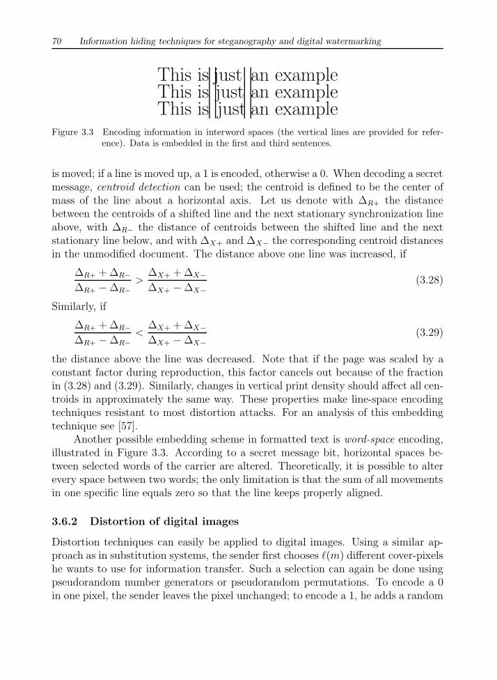
Figure 3.3 Encoding information in interword spaces (the vertical lines are provided for refer-ence). Data is embedded in the first and third sentences.
is moved; if a line is moved up, a 1 is encoded, otherwise a 0. When decoding a secretmessage, centroid detection can be used; the centroid is defined to be the center ofmass of the line about a horizontal axis. Let us denote with ∆R+ the distancebetween the centroids of a shifted line and the next stationary synchronization lineabove, with ∆R− the distance of centroids between the shifted line and the nextstationary line below, and with ∆X+ and ∆X− the corresponding centroid distancesin the unmodified document. The distance above one line was increased, if
∆R+ + ∆R−∆R+ −∆R−
>∆X+ + ∆X−∆X+ −∆X−
(3.28)
Similarly, if
∆R+ + ∆R−∆R+ −∆R−
<∆X+ + ∆X−∆X+ −∆X−
(3.29)
the distance above the line was decreased. Note that if the page was scaled by aconstant factor during reproduction, this factor cancels out because of the fractionin (3.28) and (3.29). Similarly, changes in vertical print density should affect all cen-troids in approximately the same way. These properties make line-space encodingtechniques resistant to most distortion attacks. For an analysis of this embeddingtechnique see [57].
Another possible embedding scheme in formatted text is word-space encoding,illustrated in Figure 3.3. According to a secret message bit, horizontal spaces be-tween selected words of the carrier are altered. Theoretically, it is possible to alterevery space between two words; the only limitation is that the sum of all movementsin one specific line equals zero so that the line keeps properly aligned.
3.6.2 Distortion of digital images
Distortion techniques can easily be applied to digital images. Using a similar ap-proach as in substitution systems, the sender first chooses `(m) different cover-pixelshe wants to use for information transfer. Such a selection can again be done usingpseudorandom number generators or pseudorandom permutations. To encode a 0in one pixel, the sender leaves the pixel unchanged; to encode a 1, he adds a random
A survey of steganographic techniques 71
value ∆x to the pixel’s color. Although this approach is similar to a substitutionsystem, there is one significant difference: the LSB of the selected color values donot necessarily equal secret message bits. In particular, no cover modifications areneeded when coding a 0. Furthermore, ∆x can be chosen in a way that betterpreserves the cover’s statistical properties. The receiver compares all `(m) selectedpixels of the stego-object with the corresponding pixels of the original cover. If theith pixel differs, the ith message bit is a 1, otherwise a 0.
Many variants of the above method could be implemented: similar to the paritybit method presented in Section 3.2.4, the parity bit of a certain image region canbe altered or left unchanged in order to encode a 1 or a 0. Furthermore, imageprocessing techniques could be applied to certain image regions so that they are notvisible to an observer.
Another image distortion technique, data embedding , has been introduced bySandford et al. [59, 60]. In contrast to all distortion techniques discussed so far, dataembedding tries to modify the order of appearance of redundant data in the coverrather than to change values themselves; the embedding process therefore maintainsa “pair list” (i.e., a list of pairs of samples whose difference is smaller than a specificthreshold). The receiver can reverse the embedding process if he has access to thepair list. This list can be seen as an analogon to a key in cryptography; it normallycannot be restored out of the cover by the receiver (see [59] for details).
3.7 COVER GENERATION TECHNIQUES
In contrast to all embedding methods presented above, where secret information isadded to a specific cover by applying an embedding algorithm, some steganographicapplications generate a digital object only for the purpose of being a cover for secretcommunication.
3.7.1 Mimic functions
Due to the explosion of information traffic it can be assumed that it is impossiblefor a human being to observe all communications around the world; as noted in theconclusion of Chapter 2, such a task can only be done using automated supervisionsystems which are therefore of increasing importance. These systems check com-munication by examining keywords and the statistical profile of a message. It ispossible, for instance, to distinguish unencrypted from encrypted messages automat-ically because of their different statistical properties. Mimic functions, proposed byWayner [61], can be used to hide the identity of a message by changing its statisticalprofile in a way that it matches the profile of any innocent looking text.
72 Information hiding techniques for steganography and digital watermarking
It is well known that the English language possesses several statistical prop-erties. For instance the distribution of characters is not uniform (see for in-stance the appendix of [62] for the frequency distributions of English di- and tri-grams). This fact has been exploited in numerous data-compression techniques(e.g., the Huffman coding scheme [40]). Given an alphabet Σ and a probabilitydistribution A, the Huffman coding scheme can be used to produce a minimum-redundancy compression function fA : Σ → {0, 1}∗, where ∗ denotes the Kleene-Star (Σ∗ =
⋃i≥0{x1 · · ·xi|x1, . . . , xi ∈ Σ}). A mimic function g : Σ∗ → Σ∗ that
converts a message whose characters show a probability distribution A to a mes-sage which approximately mimics the statistical profile B, can be constructed usingtwo Huffman compression functions:
g(x) = f−1B (fA(x)) (3.30)
Thus, the file x is first compressed using a Huffman scheme with distribution A.This process will create a file of binary strings which can be interpreted as outputof a Huffman compression scheme (with distribution B) of a different file. Thisfile can be reconstructed by applying the inverse Huffman compression functionf−1
B to the file of binary strings and will act as a stego-object. Since both fA
and fB are one-to-one, the constructed mimic function will be one-to-one. Waynershowed that this function is optimal in the sense that if fA is a theoretically optimalHuffman compression function and x is a file of random bits, then f−1
A (x) is the bestapproximation of the statistical profile A which is one-to-one.
Instead of using distributions of single characters, Huffman coding schemescan be constructed to compress n characters at one time, based on the frequencydistribution of n-grams. However, the size of the compression tree created by theHuffman schemes grows exponentially with n. Wayner instead proposed to exploitthe intercharacter dependencies by creating Huffman compression functions for ev-ery string t of length n − 1 to encode probabilities for each character which mayfollow t in the file. A mimic function can be constructed out of the collection ofthese Huffman compression functions (see [61] for details).
3.7.2 Automated generation of English texts
However, mimic functions can only be used to fool machines. Since the stego-objectsare created only according to statistical profiles, the semantic component is entirelyignored. To a human observer the created texts look completely meaningless andare full of grammatical and typographical errors.
To overcome this problem, the use of context-free grammars (CFG) has beenproposed; for a theoretical overview of CFG see [63]. Let G = 〈V, Σ, Π, S〉 be a CFG,where V is the set of variables, Σ the set of terminal symbols, Π ⊆ V×(V ∪ Σ)∗
A survey of steganographic techniques 73
the set of productions and S ∈ V the start symbol. The productions can be seenas a substitution rule; they convert a variable into a string containing terminal orvariable symbols. A string s ∈ Σ∗ which is defined to be a sequence of termi-nal symbols is said to be generated by G (formally: s ∈ L(G)) if s can be pro-duced successively from the start symbol S by substituting variables by sequencesof terminal or variable symbols according to Π. For example, from the grammar〈{S, A, B, C}, {A, . . . , Z, a . . . , z}, Π, S〉 with
Π = { S → Alice B, S → Bob B, S → Eve B, S → I A,A → am working, A → am lazy, A → am tired,B → is C, B → can cook,C → reading, C → sleeping, C → working}
the sentences I am lazy, Alice is reading, etc. can be derived. If for everystring s ∈ L(G) there exists exactly one way s can be generated from the startsymbol, the grammar is said to be unambiguous.
Unambiguous grammars can be used as a steganographic tool. Wayner [61,64] proposed an extension to the technique of mimic functions. Given a set ofproductions, we assign a probability to each possible production for variable Vi. Inour example above, we could choose
Π = { S →0.5 Alice B, S →0.3 Bob B, S →0.1 Eve B, S →0.1 I A,A →0.3 am working, A →0.4 am lazy, A →0.3 am tired,B →0.5 is C, B →0.5 can cook,C →0.5 reading, C →0.1 sleeping, C →0.4 working}
Let ΠVi= {πi,1, . . . , πi,n} be the set of all productions associated with variable
Vi. The sender then constructs a Huffman compression function fΠifor every set
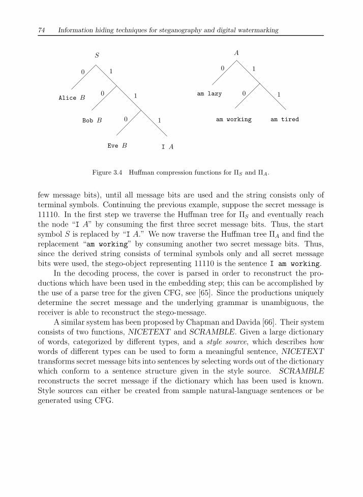
Πi. In Figure 3.4 possible Huffman trees for ΠS and ΠA are shown. Huffmancompression functions can easily be derived out of these trees; for example theproduction “Eve B” will be encoded as 110, “A am tired” as 11, etc.
For steganographic purposes, the inverse Huffman compression functions willbe used. In the encoding step, the sender derives one specific string out of the CFGwhich will act as the stego-object. Starting from the start symbol S, the leftmostvariable Vi is changed by a production. This production is determined by the secretmessage and the Huffman compression function for ΠVi
. Specifically, the Huffmantree is traversed according to the next bits of the secret message until a node of thetree is reached. The start symbol is then substituted by the production which canbe found at this node of the tree. This process is iterated (i.e., the leftmost variableis exchanged by a production which is determined by its Huffman tree and the next
74 Information hiding techniques for steganography and digital watermarking
10
S A
1
1
I AEve B
Alice B
Bob B
0
0
1
1
0
0
am tiredam working
am lazy
Figure 3.4 Huffman compression functions for ΠS and ΠA.
few message bits), until all message bits are used and the string consists only ofterminal symbols. Continuing the previous example, suppose the secret message is11110. In the first step we traverse the Huffman tree for ΠS and eventually reachthe node “I A” by consuming the first three secret message bits. Thus, the startsymbol S is replaced by “I A.” We now traverse the Huffman tree ΠA and find thereplacement “am working” by consuming another two secret message bits. Thus,since the derived string consists of terminal symbols only and all secret messagebits were used, the stego-object representing 11110 is the sentence I am working.
In the decoding process, the cover is parsed in order to reconstruct the pro-ductions which have been used in the embedding step; this can be accomplished bythe use of a parse tree for the given CFG, see [65]. Since the productions uniquelydetermine the secret message and the underlying grammar is unambiguous, thereceiver is able to reconstruct the stego-message.
A similar system has been proposed by Chapman and Davida [66]. Their systemconsists of two functions, NICETEXT and SCRAMBLE. Given a large dictionaryof words, categorized by different types, and a style source, which describes howwords of different types can be used to form a meaningful sentence, NICETEXTtransforms secret message bits into sentences by selecting words out of the dictionarywhich conform to a sentence structure given in the style source. SCRAMBLEreconstructs the secret message if the dictionary which has been used is known.Style sources can either be created from sample natural-language sentences or begenerated using CFG.

A survey of steganographic techniques 75
3.8 CONCLUSION
In this chapter we gave an overview of different steganographic methods which havebeen proposed in the literature during the last few years. Many flexible and simplemethods exist for embedding information in noisy communication channels.
However, covers and messages tend to have unique patterns a steganalyst couldexploit. Most of the simple techniques can be broken by careful analysis of thestatistical properties of the channel’s noise. Images and many other signals weresubject to quantization, filters, transformations, format converters, etc. Most ofthese techniques left some sort of “fingerprints” in the data. All these problemsmust be addressed when designing a steganographic system; methods which usethese properties to break secret communication will be outlined in the next chapter.
REFERENCES
[1] Foley, J., et al., Computer Graphics, Principles and Practice, Reading, MA: AddisonWesley, 1990.
[2] Bender, W., D. Gruhl, and N. Morimoto, “Techniques for data hiding,” IBM SystemsJournal , vol. 35, no. 3/4, 1996, pp. 131–336.
[3] Moller, S., A. Pfitzmann, and I. Stirand, “Computer Based Steganography: How ItWorks and Why Therefore Any Restrictions on Cryptography Are Nonsense, At Best,”in Information Hiding: First International Workshop, Proceedings, vol. 1174 of LectureNotes in Computer Science, Springer, 1996, pp. 7–21.
[4] Gruhl, D., A. Lu, and W. Bender, “Echo Hiding,” in Information Hiding: First Interna-tional Workshop, Proceedings, vol. 1174 of Lecture Notes in Computer Science, Springer,1996, pp. 295–316.
[5] Kurak, C., and J. McHughes, “A Cautionary Note On Image Downgrading,” in IEEEComputer Security Applications Conference 1992, Proceedings, IEEE Press, 1992, pp.153–159.
[6] van Schyndel, R. G., A. Tirkel, and C. F. Osborne, “A Digital Watermark,” in Pro-ceedings of the IEEE International Conference on Image Processing, vol. 2, 1994, pp.86–90.
[7] Johnson, N. F., and S. Jajodia, “Exploring Steganography: Seeing the Unseen,” IEEEComputer , vol. 31, no. 2, 1998, pp. 26–34.
[8] Gerzon, M. A., and P. G. Graven, “A High-Rate Buried-Data Channel for Audio CD,”Journal of the Audio Engineering Society, vol. 43, no. 1/2, 1995, pp. 3–22.
[9] “StegoDos—Black Wolf’s Picture Encoder v0.90B,” <ftp://ftp.csua.berkeley.edu/pub/cypherpunks/steganography/stegodos.zip>, 1993.
[10] Brown, A., “S-Tools for Windows,” <ftp://idea.sec.dsi.unimi.it/pub/security/crypt/code/s-tools4.zip>, 1996.
[11] Hastur, H., “Mandelsteg,” <ftp://idea.sec.dsi.unimi.it/pub/security/crypt/code/steg.tar.Z>, 1994.
[12] Machado, R., “EzStego, Stego Online, Stego,” <http://www.stego.com>, 1997.

76 Information hiding techniques for steganography and digital watermarking
[13] Maroney, C., “Hide and Seek,” <ftp://ftp.csua.berkeley.edu/pub/cypherpunks/steganography/hdsk41b.zip>, <http://www.rugeley.demon.co.uk/security/hdsk50.zip>, 1994–1997.
[14] Repp, H., “Hide4PGP,” <http://www.rugeley.demon.co.uk/security/hide4pgp.zip>, 1996.
[15] Arachelian, R., “White Noise Storm,” <ftp://ftp.csua.berkeley.edu/pub/cypherpunks/steganography/wns210.zip>, 1994.
[16] Hansmann, F., “Steganos, Deus Ex Machina Communications,” <http://www.steganography.com/>, 1996.
[17] Menezes, A. J., P. C. van Oorschot, and S. A. Vanstone, Handbook of Applied Cryptog-raphy, Boca Raton: CRC Press, 1996.
[18] Aura, T., “Practical Invisibility in Digital Communication,” in Information Hiding: FirstInternational Workshop, Proceedings, vol. 1174 of Lecture Notes in Computer Science,Springer, 1996, pp. 265–278.
[19] Luby, M., and C. Rackoff, “How to Construct Pseudorandom Permutations from Pseu-dorandom Functions,” SIAM Journal on Computation, vol. 17, no. 2, 1988, pp. 373–386.
[20] Naor, M., and O. Reingold, “On the Construction of Pseudorandom Permutations: Luby-Rackoff Revisited,” Journal of Cryptology, vol. 12, no. 1, 1999, pp. 29–66.
[21] Bell, D. E., and L. J. LaPadula, “Secure Computer Systems: Mathematical Founda-tions,” Mitre Report ESD-TR-73-278 (Vol. I–III), Mitre Corporation, Bedford, MA,Apr. 1974.
[22] Fridrich, J., “A New Steganographic Method for Palette-Based Images,” in Proceedingsof the IS&T PICS conference, Savannah, Georgia, Apr. 1998, pp. 285–289.
[23] Matsui, K., and K. Tanaka, “Video-Steganography: How to Secretly Embed a Signaturein a Picture,” IMA Intellectual Property Project Proceedings, vol. 1, no. 1, 1994, pp. 187–205.
[24] Baharav, Z., and D. Shaked, “Watermarking of Dither Halftoned Images,” in Proceedingsof the SPIE 3657, Security and Watermarking of Multimedia Content , 1999, pp. 307–316.
[25] Zhao, J., and E. Koch, “Embedding Robust Labels into Images for Copyright Protec-tion,” in Proceedings of the International Conference on Intellectual Property Rightsfor Information, Knowledge and New Techniques, Munchen, Wien: Oldenbourg Verlag,1995, pp. 242–251.
[26] “CCITT Recommendation T6: Facsimile Coding Schemes and Coding Control Functionsfor Group 4 Facsimile Apparatus for Document Transmission,” 1984.
[27] Anderson, R. J., R. Needham, and A. Shamir, “The Steganographic File System,” inProceedings of the Second International Workshop on Information Hiding, vol. 1525 ofLecture Notes in Computer Science, Springer, 1998, pp. 73–82.
[28] “ScramDisk: Free Hard Drive Encryption For Windows 95 & 98,” <http://www.scramdisk.clara.net>, 1998.
[29] Handel, T. G., and M. T. Sandford, “Data Hiding in the OSI Network Model,” inInformation Hiding: First International Workshop, Proceedings, vol. 1174 of LectureNotes in Computer Science, Springer, 1996, pp. 23–38.
[30] Cox, I., et al., “A Secure, Robust Watermark for Multimedia,” in Information Hid-ing: First International Workshop, Proceedings, vol. 1174 of Lecture Notes in ComputerScience, Springer, 1996, pp. 185–206.
[31] Koch, E., and J. Zhao, “Towards Robust and Hidden Image Copyright Labeling,” inIEEE Workshop on Nonlinear Signal and Image Processing, Jun. 1995, pp. 452–455.
A survey of steganographic techniques 77
[32] Koch, E., J. Rindfrey, and J. Zhao, “Copyright Protection for Multimedia Data,” inProceedings of the International Conference on Digital Media and Electronic Publishing,Leeds, UK, Dec. 1994.
[33] O Runaidh, J. J. K., F. M. Boland, and O. Sinnen, “Watermarking Digital Images forCopyright Protection,” in Electronic Imaging and the Visual Arts, Proceedings, Feb.1996.
[34] Xia, X., C. G. Boncelet, and G. R. Arce, “A Multiresolution Watermark for DigitalImages,” in Proceedings of the IEEE International Conference on Image Processing(ICIP’97), 1997.
[35] Rhodas, G. B., “Method and Apparatus Responsive to a Code Signal Conveyed Througha Graphic Image,” U.S. Patent 5,710,834, 1998.
[36] Swanson, M. D., B. Zhu, and A. H. Tewfik, “Transparent Robust Image Watermarking,”in Proceedings of the IEEE International Conference on Image Processing, vol. 3, 1996,pp. 211–214.
[37] Langelaar, G., J. van der Lubbe, and R. Lagendijk, “Robust Labeling Methods for CopyProtection of Images,” in Proceedings of the SPIE vol. 3022, Storage and Retrieval forImage and Video Databases V , 1997, pp. 298–309.
[38] Pennebaker, W. B., and J. L. Mitchell, JPEG Still Image Compression Standard , NewYork: Van Nostrand Reinhold, 1993.
[39] Wallace, G. K., “The JPEG Still Picture Compression Standard,” Communications ofthe ACM , vol. 34, no. 4, 1991, pp. 30–44.
[40] Huffman, D. A., “A Method for the Construction of Minimum-Redundancy Codes,”Proceedings of the IRE , vol. 40, no. 10, 1952, pp. 1098–1101.
[41] Smoot, S., and L. A. Rowe, “DCT Coefficient Distributions,” in Proceedings of the SPIE2657, Human Vision and Electronic Imaging , 1996, pp. 403–411.
[42] Moore, B. C. J., An Introduction to the Psychology of Hearing, London: Academic Press,1989.
[43] Chang, L., and I. S. Moskowitz, “Critical Analysis of Security in Voice Hiding Tech-niques,” in Proceedings of the International Conference on Information and Communi-cations Security, vol. 1334 of Lecture Notes in Computer Science, Springer, 1997, pp.203–216.
[44] Cachin, C., “An Information-Theoretic Model for Steganography,” in Proceedings of theSecond International Workshop on Information Hiding, vol. 1525 of Lecture Notes inComputer Science, Springer, 1998, pp. 306–318.
[45] Willems, F. M., “Universal Data Compression and Repetition Times,” IEEE Transac-tions on Information Theory, 1989, pp. 337–343.
[46] Upham, D., “Jpeg-Jsteg, modification of the independent JPEG group’s JPEG software(release 4) for 1-bit steganography in JFIF output files,” <ftp://ftp.funet.fi/pub/crypt/steganography/>, 1992–1997.
[47] Westfeld, A., and G. Wolf, “Steganography in a Video Conferencing System,” in Proceed-ings of the Second International Workshop on Information Hiding, vol. 1525 of LectureNotes in Computer Science, Springer, 1998, pp. 32–47.
[48] Hartung, F., and B. Girod, “Copyright Protection in Video Delivery Networks byWatermarking of Pre-Compressed Video,” in Multimedia Applications, Services andTechniques—ECMAST 97 , vol. 1242 of Lecture Notes in Computer Science, Springer,1997, pp. 423–436.
[49] Hartung, F., and B. Girod, “Watermarking of Uncompressed and Compressed Video,”
78 Information hiding techniques for steganography and digital watermarking
Signal Processing , vol. 66, no. 3, 1998, pp. 283–301.[50] Pickholtz, R. L., D. L. Schilling, and L. B. Milstein, “Theory of Spread-Spectrum
Communications—A Tutorial,” IEEE Transactions on Communications, vol. 30, no. 5,1982, pp. 855–884.
[51] Tirkel, A. Z., G. A. Rankin, and R. van Schyndel, “Electronic Watermark,” in Digi-tal Image Computing, Technology and Applications—DICTA 93, Macquarie University,1993, pp. 666–673.
[52] Smith, J., and B. Comiskey, “Modulation and Information Hiding in Images,” in Infor-mation Hiding: First International Workshop, Proceedings, vol. 1174 of Lecture Notesin Computer Science, Springer, 1996, pp. 207–227.
[53] Marvel, L. M., C. G. Bonclet, and C. T. Retter, “Reliable Blind Information Hiding forImages,” in Proceedings of the Second International Workshop on Information Hiding,vol. 1525 of Lecture Notes in Computer Science, Springer, 1998, pp. 48–61.
[54] Pitas, I., “A Method for Signature Casting on Digital Images,” in International Confer-ence on Image Processing, vol. 3, IEEE Press, 1996, pp. 215–218.
[55] Maxemchuk, N. F., “Electronic Document Distribution,” AT&T Technical Journal ,September/October 1994, pp. 73–80.
[56] Low, S. H., et al., “Document Marking and Identification Using Both Line and WordShifting,” in Proceedings of Infocom’95 , 1995, pp. 853–860.
[57] Low, S. H., N. F. Maxemchuk, and A. M. Lapone, “Document Identification for CopyrightProtection Using Centroid Detection,” IEEE Transactions on Communications, vol. 46,no. 3, 1998, pp. 372–383.
[58] Low, S. H., and N. F. Maxemchuk, “Performance Comparison of Two Text MarkingMethods,” IEEE Journal on Selected Areas in Communications, vol. 16, no. 4, 1998,pp. 561–572.
[59] Sandford, M. T., J. N. Bradley, and T. G. Handel, “Data Embedding Method,” inProceedings of the SPIE 2615, Integration Issues in Large Commercial Media DeliverySystems, 1996, pp. 226–259.
[60] Sandford, M. T., T. G. Handel, and J. M. Ettinger, “Data Embedding in DegenerateHosts,” Technical Report LA-95-4446UR, Los Alamos National Laboratory, 1996.
[61] Wayner, P., “Mimic Functions,” Cryptologia, vol. XVI/3, 1992, pp. 193–214.[62] “Basic Cryptanalysis,” Headquarters Department of the Army, Field Manual NO 34-40-
2, <ftp://ftp.ox.ac.uk/cryptanalysis/basic_cryptanalysis.ps.tar.gz>.[63] Hopcroft, J. E., and J. D. Ullman, Introduction to Automata Theory, Languages and
Computation, Reading, MA: Addison Wesley, 1979.[64] Wayner, P., “Strong Theoretical Steganography,” Cryptologia, vol. XIX/3, 1995, pp. 285–
299.[65] Aho, A., R. Sethi, and J. Ullman, Compilers: Principles, Techniques and Tools, Reading
(MA): Addison Wesley, 1986.[66] Chapman, M., and G. Davida, “Hiding the Hidden: A Software System for Concealing
Ciphertext as Innocuous Text,” in Proceedings of the International Conference on Infor-mation and Communications Security, vol. 1334 of Lecture Notes in Computer Science,Springer, 1997, pp. 335–345.
Related Documents

![Steganographic Watermarking for Documents - CNC · Steganographic Watermarking for Documents Benjamín Barán, Santiago Gómez and Víctor Bogarín Email: [bbaran, vbogarin]@cnc.una.py](https://static.cupdf.com/doc/110x72/5b48ed9b7f8b9aa4148dcad3/steganographic-watermarking-for-documents-steganographic-watermarking-for.jpg)