CHAPTER 3 CHAPTER 3 NETWORKS 1: NETWORKS 1: 0909201-01 0909201-01 23 September 2002 – Lecture 3a ROWAN UNIVERSITY ROWAN UNIVERSITY College of Engineering College of Engineering Professor Peter Mark Jansson, PP PE Professor Peter Mark Jansson, PP PE DEPARTMENT OF ELECTRICAL & COMPUTER ENGINEERING DEPARTMENT OF ELECTRICAL & COMPUTER ENGINEERING Autumn Semester 2002 Autumn Semester 2002

CHAPTER 3
Dec 31, 2015
CHAPTER 3. NETWORKS 1: 0909201-01 23 September 2002 – Lecture 3a ROWAN UNIVERSITY College of Engineering Professor Peter Mark Jansson, PP PE DEPARTMENT OF ELECTRICAL & COMPUTER ENGINEERING Autumn Semester 2002. networks I. Announcements – Homework 2 answers posted today - PowerPoint PPT Presentation
Welcome message from author
This document is posted to help you gain knowledge. Please leave a comment to let me know what you think about it! Share it to your friends and learn new things together.
Transcript
CHAPTER 3CHAPTER 3
NETWORKS 1: NETWORKS 1: 0909201-010909201-01 23 September 2002 – Lecture 3a
ROWAN UNIVERSITYROWAN UNIVERSITY
College of EngineeringCollege of Engineering
Professor Peter Mark Jansson, PP PEProfessor Peter Mark Jansson, PP PEDEPARTMENT OF ELECTRICAL & COMPUTER ENGINEERINGDEPARTMENT OF ELECTRICAL & COMPUTER ENGINEERING
Autumn Semester 2002Autumn Semester 2002

networks I
Announcements – Homework 2 answers posted today
Returned after test Tuesday First Test Tomorrow Ch. 3: 24 Sep Lab 1 assignment is due
Sec 1: TODAY - 23 Sep Sec 2: TOMORROW - 24 Sep
networks I
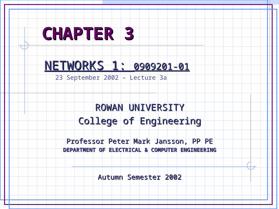
Today’s Learning Objectives – Define voltage/current divider circuits Analyze series V-sources Analyze parallel current sources Reduce resistive circuits Analyze DC circuits with passive and
active elements including: resistance and power sources

chapter 3 - overview electric circuit applications - DONE define: node, closed path, loop - DONE Kirchoff’s Current Law - DONE Kirchoff’s Voltage Law - DONE a voltage divider circuit parallel resistors and current division series V-sources / parallel I-sources resistive circuit analysis reduction

KVL
+V - vR1 - vR2 = 0
iV = iR1 = iR2 = i
+V = iR1 + iR2
V = i(R1 + R2)
R2= 20
V= 5v
R1=10
+
_
+ _
LOOP 1+_
Start
i = V/(R1 + R2)
vR! = iR1 = VR1 /(R1 + R2)
vR2 = iR2 = VR2/(R1 + R2)

SERIES RESISTORS
+V - vR1 - vR2 = 0
iV = iR1 = iR2 = i
+V = iR1 + iR2
V = i(R1 + R2)
R2= 20
V= 5v
R1=10
+
_
+ _
LOOP 1+_
Start
i = V/(R1 + R2)
vR! = iR1 = VR1 /(R1 + R2)
vR2 = iR2 = VR2/(R1 + R2)
VOLTAGE DIVIDER
NOTE

SERIES RESISTORS
resistors attached in a “string” can be added together to get an equivalent resistance.
R = 2 R = 3
R = 4R = 9
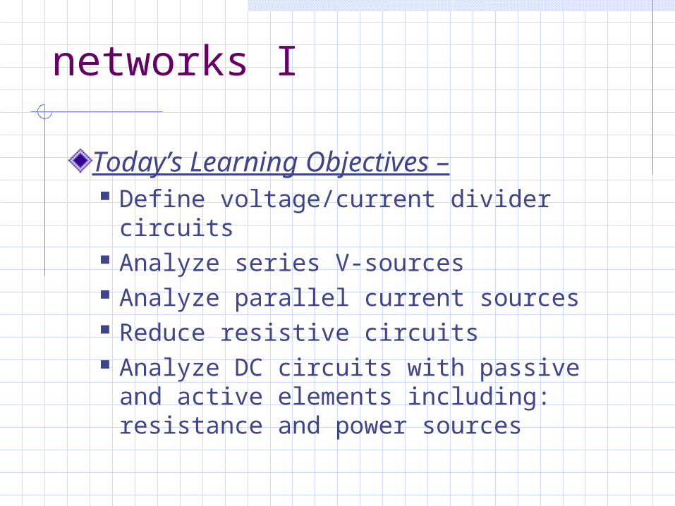
R2= 20
I=5A
R1=10
R3= 5v2=20v
+
_v3=20v
+
_
v1=50v+ _
i1
i2 i3
I
Node 1 +I - i1 = 0
Node 2 +i1 - i2 - i3 = 0
Node 3 +i2 + i3 - I = 0
i2 = v2/R2 i3 = v3/R3
Node 1 Node 2
Node 3
Use KCL andOhm’s Law
CURRENT DIVIDER

series voltage sources
when connected in series, a group of voltage sources can be treated as one voltage source whose equivalent voltage = all source voltages unequal voltage sources are not to be connected in parallel

parallel current sources
when connected in parallel, a group of current sources can be treated as one current source whose equivalent current
= all source currents unequal current sources are not to be connected in series

PROBLEM SOLVING METHOD
+
_
+ _++
_
+
__
node1 node2 node3
node4
Ra Rb
Rcvs is
ia ib
ic
va vb
vc
ivs
visloop1 loop2

steps taken
Apply P.S.C. to passive elements. Show current direction at voltages sources. Show voltage direction at current sources. Name nodes and loops. Name elements and sources. Name currents and voltages.
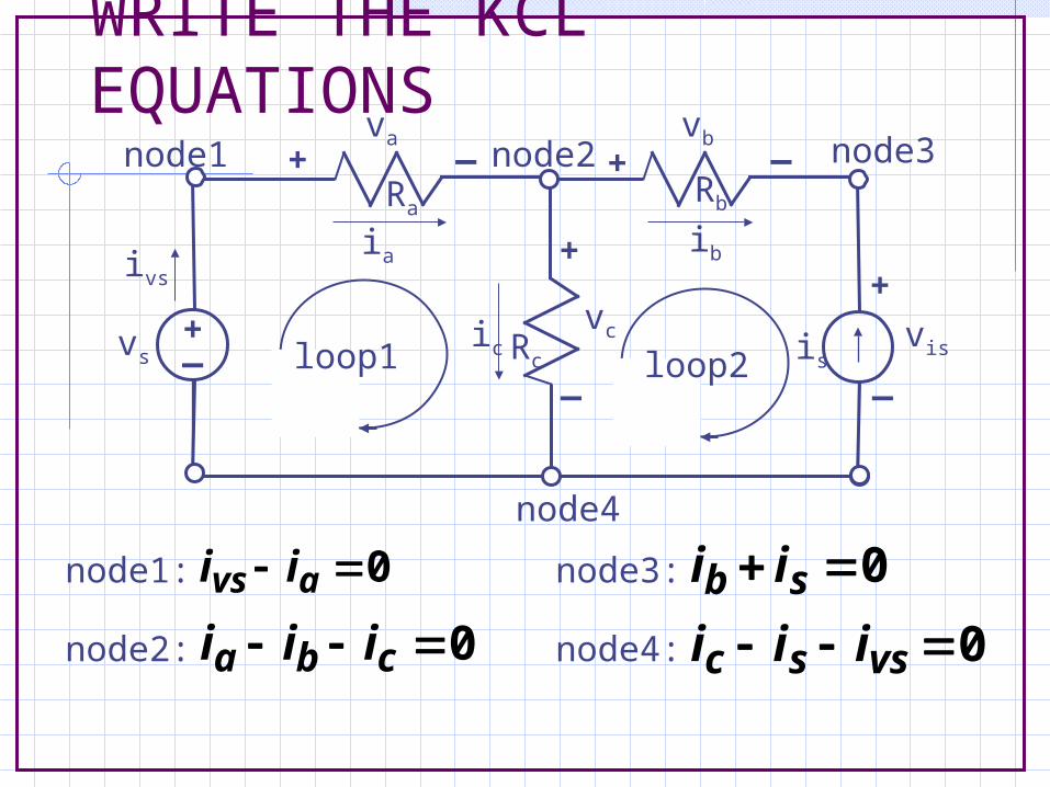
WRITE THE KCL EQUATIONS
0 avs ii
0 cba iii
0 sb ii
0 vssc iii
node1:
node2: node4:
node3:
+
_
+ _+
+
_
+
__
node1 node2 node3
node4
Ra Rb
Rcvs is
ia ib
ic
va vb
vc
ivs
visloop1 loop2

WRITE THE KVL EQUATIONS
+
_
+ _+
+
_
+
__
node1 node2 node3
node4
Ra Rb
Rcvs is
ia ib
ic
va vb
vc
ivs
visloop1 loop2
0 cas vvv 0 isbc vvv
loop1: loop2:

WRITE SUPPLEMENTARYEQUATIONS
+
_
+ _+
+
_
+
__
node1 node2 node3
node4
Ra Rb
Rcvs is
ia ib
ic
va vb
vc
ivs
visloop1 loop2
cccbbbaaa R/viR/viR/vi
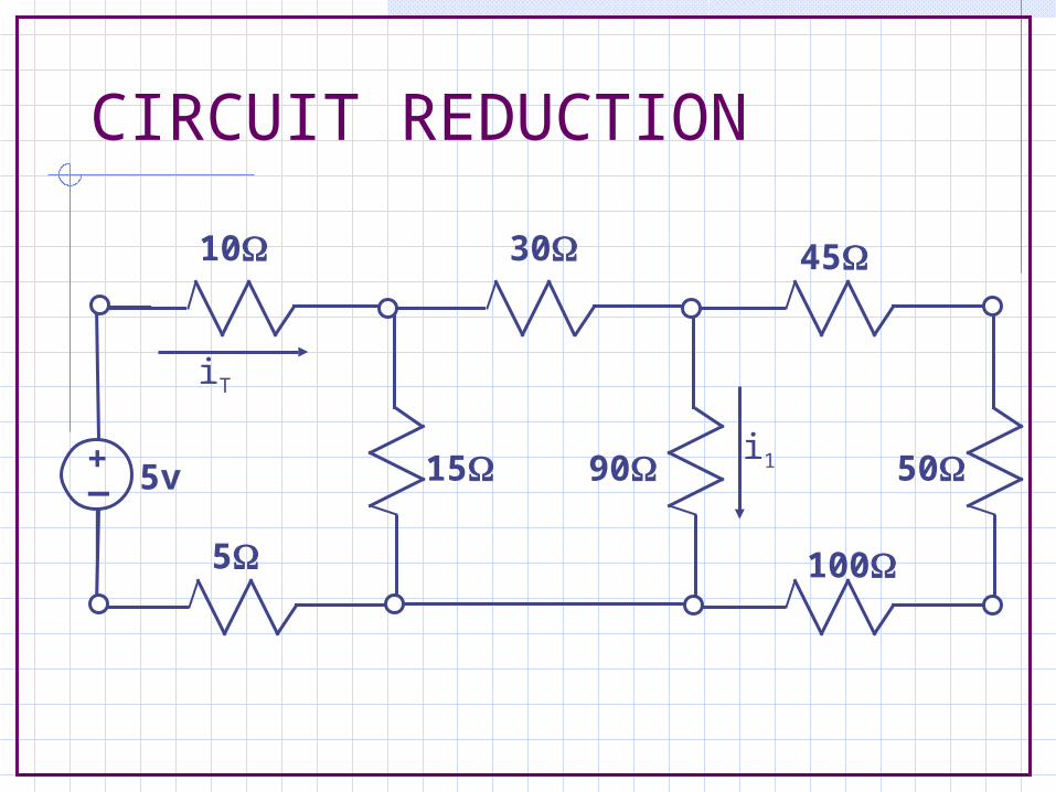
CIRCUIT REDUCTION
+_
10 30
5
15 90
45
50
100
i15v
iT

+_
10 30
5
15 90
45
50
100
i15v
iT
Begin with loop on far right.Combine the three resistors that are in series.Req = 45+50+100 = 195
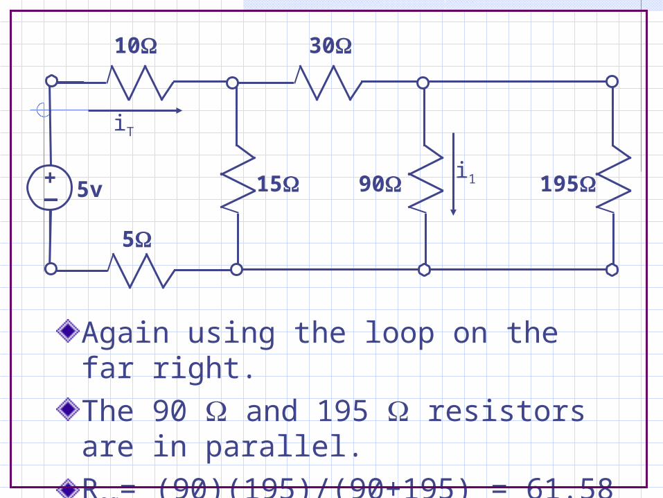
Again using the loop on the far right.The 90 and 195 resistors are in parallel.Req= (90)(195)/(90+195) = 61.58
+_
10 30
5
15 90 195i15v
iT

Still working with the loop on the far right.The 30 and the 61.58 resistors are in series.Req = 30 + 61.58 = 91.58
10 30
+_
5
15 61.585v
iT
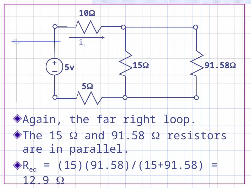
Again, the far right loop.The 15 and 91.58 resistors are in parallel.Req = (15)(91.58)/(15+91.58) = 12.9
10
+_
5
15 91.585v
iT
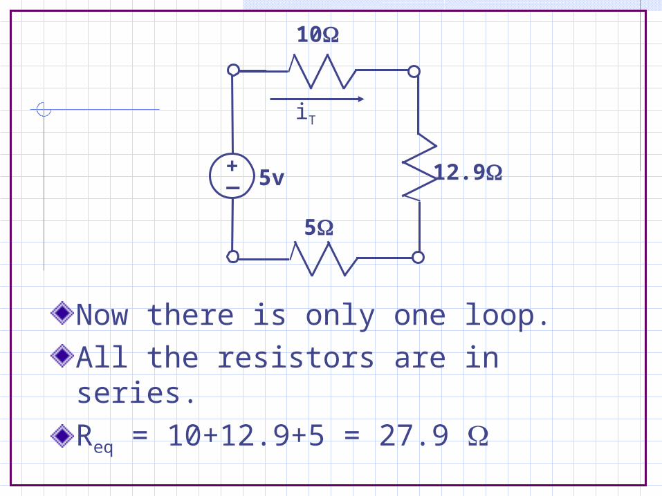
Now there is only one loop.All the resistors are in series.Req = 10+12.9+5 = 27.9
10
+_
5
12.95v
iT

Use Ohm’s Law to determine iT.
iT = 5/27.9 = 0.179A
iT flows in all three resistors, the 12.9 resistor is the equivalent resistance of the entire circuit beyond points a and b.
+_ 27.95v
iT
10
+_
5
12.95v
0.179A
a
b
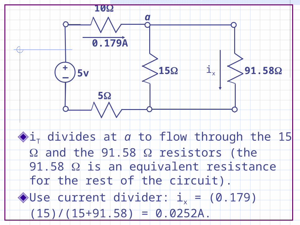
iT divides at a to flow through the 15 and the 91.58 resistors (the 91.58 is an equivalent resistance for the rest of the circuit). Use current divider: ix = (0.179)(15)/(15+91.58) = 0.0252A.
10
+_
5
15 91.585v
0.179A
ix
a

No calculations are required at this step because the 0.0252A is flowing through both resistors in the right loop.This circuit must be drawn however, because the 61.58 resistor is an equivalent for the circuit to the right of a and b.
10 30
+_
5
15 61.585v
0.179A0.0252A
a
b

Use the current divider equation again to determine i1.
i1 = (0.0252)(195)/(90+195) = 0.01724A = 17.24mA.The current through the 195 resistor is 0.0252 - 0.01724 = 7.96mA
+_
10 30
5
15 90 195i15v
0.179A 0.0252A
a
b

One Minute Paper
please complete handout no names leave in box on leaving thanks
Related Documents