Chapter 23 Transformers and Coupled Circuits

Welcome message from author
This document is posted to help you gain knowledge. Please leave a comment to let me know what you think about it! Share it to your friends and learn new things together.
Transcript
Chapter 23
Transformers andCoupled Circuits
2
Transformer Construction• Transformer is a magnetically coupled
circuit
• It consists of two coils wound on a common core
3
Transformer Construction
• Power flows from one circuit to the other circuit – Through the medium of the magnetic field
4
Transformer Construction• There is no electrical connection between
the two coils
• Coil (winding) on side of the transformer to which we apply power is called primary
5
Transformer Construction• Coil on side to which we connect the load
is called the secondary
6
Transformer Construction• Iron-core transformers
– Generally used for low-frequency applications (such as audio and power)
• Iron core provides an easy path for magnetic flux
7
Transformer Construction
• Two basic construction types– Core and shell
• Each type uses laminated sheets of metal to reduce eddy currents
8
Transformer Construction• Air-core and ferrite-core types
– Used for high-frequency applications (such as radio frequencies)
9
Transformer Construction
• These do not have high hysteresis and eddy-current losses of iron-core transformers
• Ferrite– Increases coupling between coils while
maintaining low losses
10
Transformer Construction
• Transformer may be used to change polarity of an ac voltage – Depending on the directions of its windings
11
Transformer Construction• If most of the flux produced by one of the
coils links the other– Coils are tightly coupled– Otherwise loosely coupled
• All transformer operations are described by Faraday’s law
12
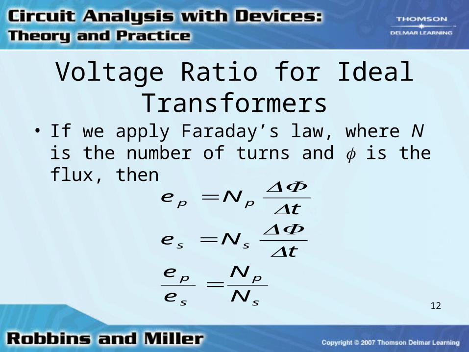
Voltage Ratio for Ideal Transformers
• If we apply Faraday’s law, where N is the number of turns and is the flux, then
s
p
s
p
ss
pp
N
N
e
et
Ne
tNe
=
=
=
ΔΔΦΔΔΦ
13
Voltage Ratio for Ideal Transformers
• Ratio of primary voltage to secondary voltage– Equal to ratio of the number of turns
14
The Turns Ratio
• Turns ratio (or the transformation ratio) – a = Np/Ns
• Also, ep/es = a
15
The Turns Ratio• A step-up transformer
– Secondary voltage is higher than the primary voltage (a < 1)
• A step-down transformer – Secondary voltage is lower (a > 1)
16
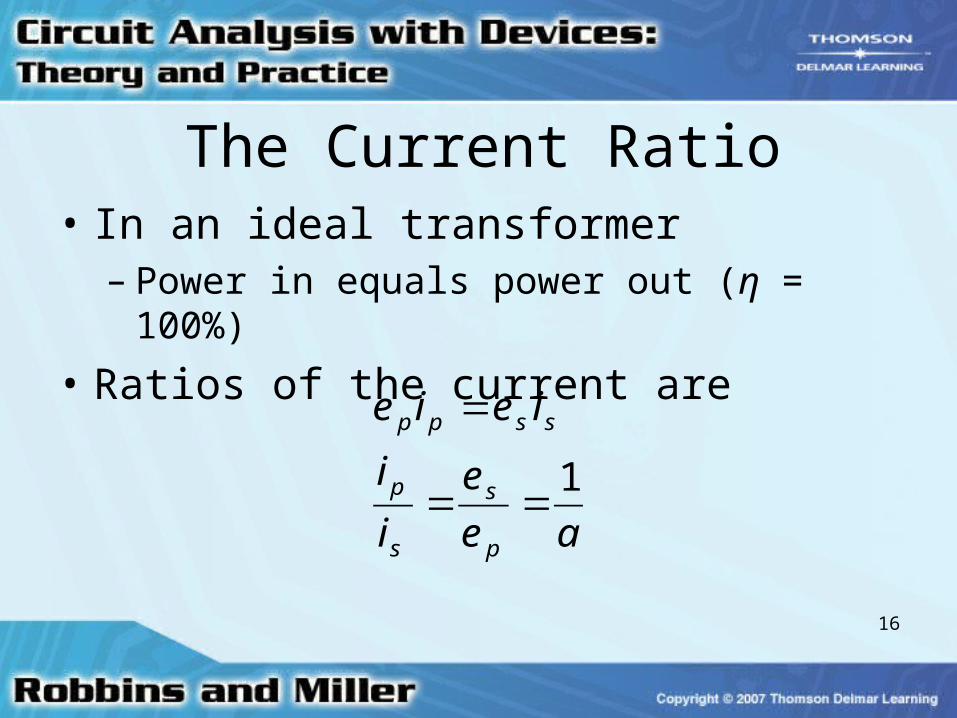
The Current Ratio• In an ideal transformer
– Power in equals power out (η = 100%)
• Ratios of the current are
ae
e
i
i
ieie
p
s
s
p
sspp
1==
=
17
The Current Ratio• If voltage is stepped up
– Current is stepped down, and vice versa
18
Reflected Impedance
• A load impedance ZL connected directly to a source is seen as ZL
• Impedance will be seen by the source differently – If a transformer is connected between the
source and the load
19
Reflected Impedance
• Reflected impedance, Zp, is given by
– Zp = a2ZL
20
Reflected Impedance• Load characteristics do not change
– Capacitive loads still look capacitive, etc.
• A transformer can make a load look larger or smaller– Depending on the turns ratio
21
Reflected Impedance• Using a transformer
– We can match loads to sources (such as amplifiers)
• Relates to the maximum power theorem discussed in a previous section
22
Transformer Ratings
• Transformers are rated in terms of voltage and apparent power
• Rated current can be determined from these ratings
23
Transformer Ratings• By dividing the apparent power rating by
the voltage rating– Rated current is determined, regardless of the
power factor
24
Power Supply Transformers• Used to convert the incoming 120 V
source to voltage levels required by circuit
• Some have a multi-tapped secondary winding to provide different voltages for different applications
25
Power Supply Transformers• Typically, an incoming voltage is
– Stepped down– Rectified– Smoothed by a filter– Passed through a voltage regulator
26
Transformers in Power Systems• Transformers are used at generating
stations to raise voltage for transmission– This lowers losses in the transmission lines
• At the user end– Voltage is stepped down
27
Transformers in Power Systems• Transformers have a split secondary
– This permits both 120-V and 240-V loads to be supplied from the same transformer
• For residential use– Single phase is used
28
Isolation Applications• Transformers are sometimes used to
isolate equipment
• Isolation transformers are often used to make measurements involving high voltages
29
Isolation Applications• They can also ensure that a grounded
metal chassis is not connected to a hot wire
30
Isolation Applications• Readings can be made on an oscilloscope
– Must have a grounded lead without shorting circuit components across ground connections by using a 1:1 transformer
31
Impedance Matching• A transformer can be used to raise or
lower apparent impedance of a load
• Impedance matching– Sometimes used to match loads to amplifiers
to achieve maximum power transfer
32
Impedance Matching• If load and source are not matched
– A transformer, with the proper turns ratio, can be inserted between them
33
Autotransformers
• In autotransformers– Primary circuit is not electrically isolated from
its secondary– They cannot be used as isolation
transformers
34
Autotransformers
• Smaller and cheaper than conventional transformers with the same load kVA
35
Practical Iron-Core Transformers• Non-ideal transformers have several
effects that cause loss of power
• Leakage flux – Will appear as small inductances in series
with the windings
36
Practical Iron-Core Transformers
• Winding resistance
• Core losses due to eddy currents and hysteresis
• Magnetizing current
37
Transformer Efficiency• Efficiency is ratio of output power to input
power– Given as a percentage.
• Losses – Due to power losses in the windings and in
core
38
Transformer Efficiency• Large transformers can have efficiencies
of 98 to 99 percent
• Smaller transformers have efficiencies of about 95 percent
39
Transformer Tests• Losses may be determined by making
tests on transformers• Short-circuit tests
– Determine losses due to resistance of windings
• Open-circuit tests will determine core losses
40
Voltage and Frequency Effects
• As applied voltage increases, core flux increases, causing greater magnetization current– Therefore, transformers should be
operated only at or near their rated voltage
41
Voltage and Frequency Effects• At very low frequencies
– Core flux and the magnetizing current increases• Causing large internal voltage drops
• At very high frequencies– Stray capacitances and inductances cause
voltage drops
42
Loosely Coupled Circuits• Circuits without an iron core, where only a
portion of the flux produced by one coil links another
• Cannot be characterized by turns ratios– They are characterized by self- and mutual
inductances
43
Loosely Coupled Circuits• Expressed by coefficient of coupling
– Air-core – Ferrite-core transformers– General inductive circuit coupling
44
Loosely Coupled Circuits
• Self-induced voltage in a coil is– v = L di/dt
• Mutually induced voltage of a coil is– v = M di/dt– M is mutual inductance between coils
45
Loosely Coupled Circuits
• In each coil– Induced voltage is the sum of its self-induced
voltage – Plus voltage mutually induced due to the
current in the other coil
46
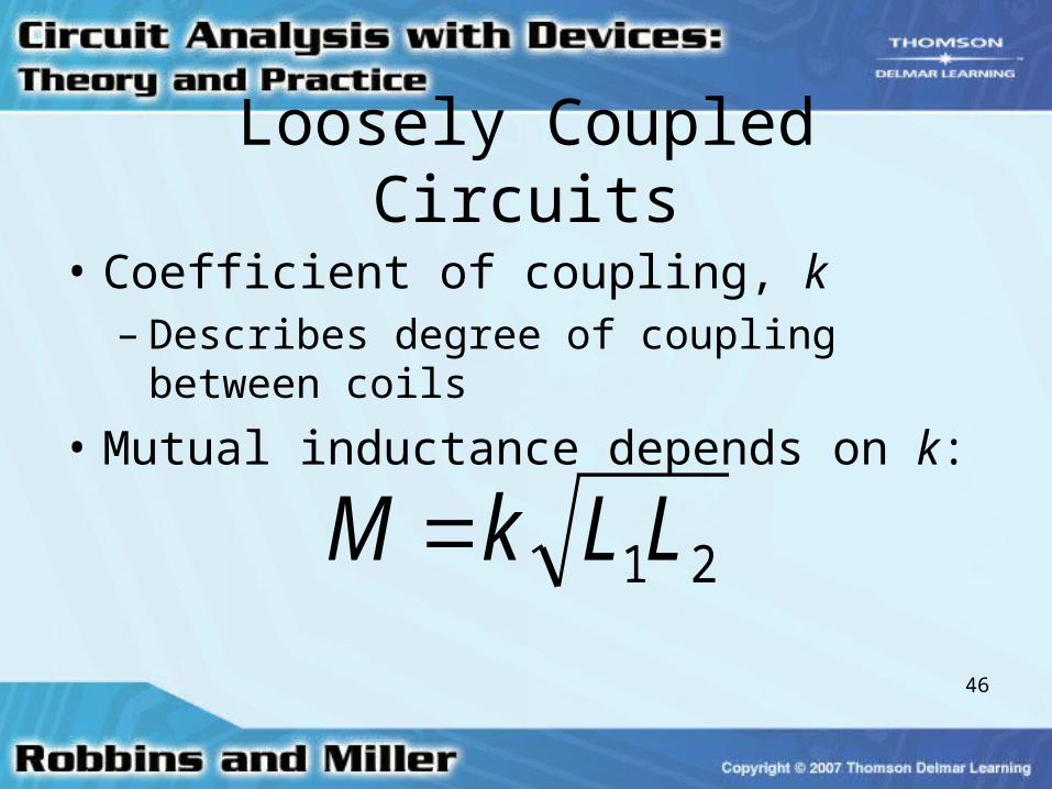
Loosely Coupled Circuits
• Coefficient of coupling, k– Describes degree of coupling between coils
• Mutual inductance depends on k:
21LLkM =
47
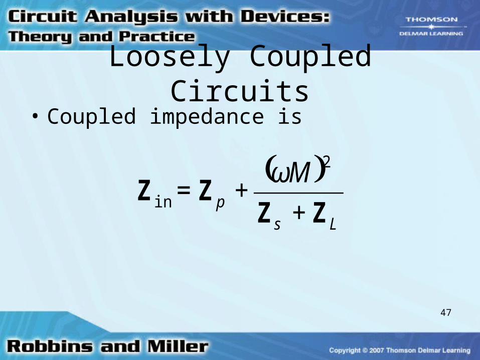
Loosely Coupled Circuits• Coupled impedance is
( )Ls
p
M
ZZZZ
++=
2ωin
Related Documents