Chapter 2 Voice over Internet Protocol Abstract This chapter presents an overview of the architecture and protocols involved in implementing VoIP networks. After the overview, the chapter dis- cusses the various factors that affect a high quality VoIP call. Furthermore, the chapter introduces various codecs and the engineering tradeoffs between delay and bandwidth. Finally, the chapter gives a detailed explanation of the currently widely used VoIP call signaling protocol, the Session Initiation Protocol or SIP. 2.1 VoIP Architecture 2.1.1 VoIP System VoIP calls can take place between phone-to-phone, PC-to-PC, and phone-to-PC. The VoIP system configuration [20], shown in Fig. 2.1, is a representative scenario. In the PC-to-PC call, as an example, once the media path is established, the analog signal is sampled at 8 kHz or another frequency depending upon the codec. These samples are then encoded in an appropriate binary format. The encoded samples are put into UDP packets of different sizes and sent over the Internet. The reverse process takes place at the receiver PC: the speech samples are extracted from the packet, processed, and then put into the play-out buffer as the analog speech signal. 2.1.2 VoIP Protocol Structure Since the 1990s, the dominant commercial architecture uses the Internet protocol suite TCP/IP, whereas VoIP uses RTP/UDP/IP. Figure 2.2 gives the complete communication network architecture. P. K. Verma and L. Wang, Voice over IP Networks, Lecture Notes in Electrical Engineering, 71, DOI: 10.1007/978-3-642-14330-4_2, Ó Springer-Verlag Berlin Heidelberg 2011 9

Welcome message from author
This document is posted to help you gain knowledge. Please leave a comment to let me know what you think about it! Share it to your friends and learn new things together.
Transcript

Chapter 2Voice over Internet Protocol
Abstract This chapter presents an overview of the architecture and protocolsinvolved in implementing VoIP networks. After the overview, the chapter dis-cusses the various factors that affect a high quality VoIP call. Furthermore, thechapter introduces various codecs and the engineering tradeoffs between delay andbandwidth. Finally, the chapter gives a detailed explanation of the currently widelyused VoIP call signaling protocol, the Session Initiation Protocol or SIP.
2.1 VoIP Architecture
2.1.1 VoIP System
VoIP calls can take place between phone-to-phone, PC-to-PC, and phone-to-PC.The VoIP system configuration [20], shown in Fig. 2.1, is a representative scenario.In the PC-to-PC call, as an example, once the media path is established, the analogsignal is sampled at 8 kHz or another frequency depending upon the codec. Thesesamples are then encoded in an appropriate binary format. The encoded samples areput into UDP packets of different sizes and sent over the Internet. The reverseprocess takes place at the receiver PC: the speech samples are extracted from thepacket, processed, and then put into the play-out buffer as the analog speech signal.
2.1.2 VoIP Protocol Structure
Since the 1990s, the dominant commercial architecture uses the Internet protocolsuite TCP/IP, whereas VoIP uses RTP/UDP/IP. Figure 2.2 gives the completecommunication network architecture.
P. K. Verma and L. Wang, Voice over IP Networks,Lecture Notes in Electrical Engineering, 71, DOI: 10.1007/978-3-642-14330-4_2,� Springer-Verlag Berlin Heidelberg 2011
9

As we know, the Internet Protocol (IP) deals only with the connectionlessdelivery of the packets, which is based on a best-effort service. TransmissionControl Protocol (TCP) is a reliable connection oriented control protocol above IP.The TCP has the following characteristics. The TCP is:
• Reliable
Each transmission of data is acknowledged by the receiver, and retransmissionis needed to ensure packet receipt in case of packet loss or error in the packet.
• Connection oriented
A virtual connection is established before any user data is transferred.
Fig. 2.2 Internet protocol stack [21]
Encoder Packetizer
De-Packetizer Playout buffer
Decoder
IP Networks
Voice
Sender
Receiver
Voice
Fig. 2.1 Conceptual diagram of a VoIP network
10 2 Voice over Internet Protocol

• Full Duplex
The transmission is provided in both directions.
• Rate Adjustment
The transmission rate increases when no congestion is detected; the transmis-sion rate reduces quickly when the sender does not receive positive acknowl-edgments from the receiver within a stipulated timeframe.
Despite these features, the TCP/IP is not suitable for real-time communications,such as speech, because the acknowledgment/retransmission feature would lead toexcessive delays [21].
In contrast to TCP, User Datagram Protocol (UDP) is classified as unreliableconnectionless protocol, which does not provide sequencing and acknowledge-ment. Without flow control and error recovery, UDP simply sends and receives IPtraffic between users in an Internet.
The Real-Time Protocol (RTP), used in conjunction with UDP, provides end-to-end network transport functions for applications transmitting real-time data,such as audio and video, over unicast and multicast network services [22]. RTPstandardizes the packet format by including the sequence numbers and time-stamps, which is convenient to multimedia applications. It should be emphasizedthat RTP in itself does not provide any mechanism to ensure timely delivery ofdata or provide other quality of service guarantees [23]. Indeed, RTP encapsulationcan only be seen at the end user location, and is not distinguishable from IPpackets without RTP at the intermediary routers.
A companion protocol RTCP does support the features as follows:
• Monitors the link• Separates packets sent on a different port number• Exchanges information about losses and delays between the end systems• Sends packets in intervals based on number of end systems and available
bandwidth
However, a continuous stream of RTP/UDP/IP packets is offered in most VoIPapplications as shown in Fig. 2.3.
As far as VoIP call signaling protocols are concerned, there are peer-to-peercontrol-signaling protocols such as H.323 protocol suites [24] and SIP [25],
Fig. 2.3 VoIP protocolstructure
2.1 VoIP Architecture 11

master–slave control-signaling protocols such as Media Gateway Control Protocol(MGCP) [26-27], and Megaco/H.248 [28].
2.2 Quality of Service
Quality of Service (QoS) is a measure of the voice quality experienced by the user.The network service provider uses it for bandwidth management over the IPnetwork in order to ensure that transmission resources consistent with the expectedQoS are available. Management of network resources is becoming increasinglyimportant as more services are added on to the Internet.
VoIP becomes an attractive and common solution for the future, since thepacket-switching technology has several advantages in both cost and architecturalaspects over the circuit-switching technology. However, questions remain as towhether the voice quality provided in VoIP networks can meet the high standardsprovided by the PSTN that users have become accustomed to, and would expectfrom any competing service. The quality of speech perceived by the VoIP user isultimately determined by parameters such as delay, jitter and packet loss [29].
2.2.1 A. Delay
Due to the interactive nature of voice communication, delay becomes a primaryparameter of concern in the QoS measure for VoIP networks. It is composed oftransmission delay, queuing delay, processing delay and propagation delay [30].The transmission delay is dependent on the channel capacity in bits per second(bps). Queuing delay is the time the packets are queued in the buffer before beingprocessed. Processing delay is incurred at the end points, e.g., in processing packetheaders, and in coding/decoding voice signals. Propagation delay depends on thedistance traveled and the transmission medium, such as coax, fiber, or wirelesschannel. The propagation delay is generally negligible when compared to the othercomponents of delay in an end-to-end VoIP scenario.
International Telecommunications Union-Telephony (ITU-T) RecommendationG.114 [31] provides one-way transmission delay specifications for voice. Thespecification is presented in Table 2.1. It has been shown that a mouth-to-ear delayof over 150 milliseconds (ms) is intolerable to VoIP users, and the delay betweensuccessive packets must be lower than 20 ms for uninterrupted and smooth hearing[33]. Studies have shown that several techniques such as Weighted Fair Queuing,Weighted Round Robin, Priority Round Robin, Priority Queuing, or Class-basedQueuing [34], can reduce the network delay.
In this book, we largely focus on the impact of queuing delay on VoIP net-works. Since voice traffic has higher priority over data traffic, the queuingbehavior of the voice packets is analyzed independently from the data packets. It is
12 2 Voice over Internet Protocol
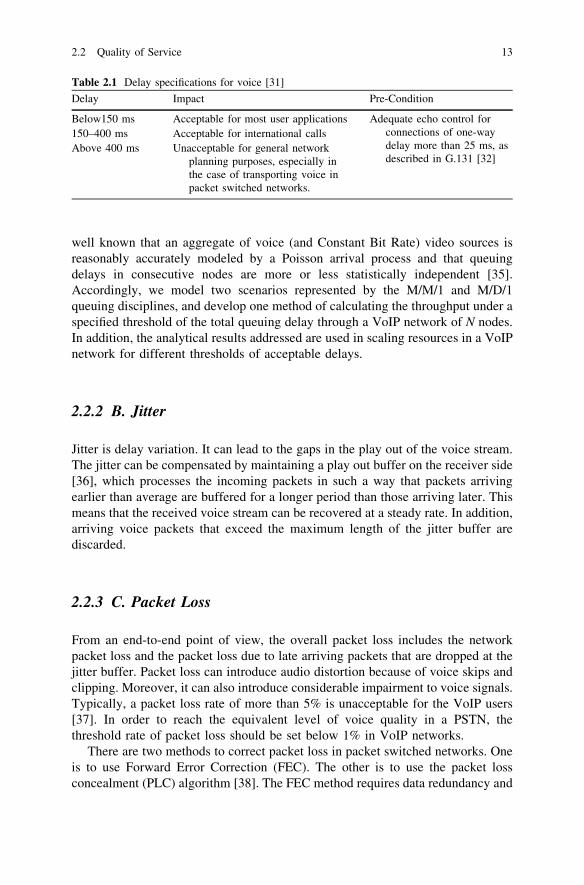
well known that an aggregate of voice (and Constant Bit Rate) video sources isreasonably accurately modeled by a Poisson arrival process and that queuingdelays in consecutive nodes are more or less statistically independent [35].Accordingly, we model two scenarios represented by the M/M/1 and M/D/1queuing disciplines, and develop one method of calculating the throughput under aspecified threshold of the total queuing delay through a VoIP network of N nodes.In addition, the analytical results addressed are used in scaling resources in a VoIPnetwork for different thresholds of acceptable delays.
2.2.2 B. Jitter
Jitter is delay variation. It can lead to the gaps in the play out of the voice stream.The jitter can be compensated by maintaining a play out buffer on the receiver side[36], which processes the incoming packets in such a way that packets arrivingearlier than average are buffered for a longer period than those arriving later. Thismeans that the received voice stream can be recovered at a steady rate. In addition,arriving voice packets that exceed the maximum length of the jitter buffer arediscarded.
2.2.3 C. Packet Loss
From an end-to-end point of view, the overall packet loss includes the networkpacket loss and the packet loss due to late arriving packets that are dropped at thejitter buffer. Packet loss can introduce audio distortion because of voice skips andclipping. Moreover, it can also introduce considerable impairment to voice signals.Typically, a packet loss rate of more than 5% is unacceptable for the VoIP users[37]. In order to reach the equivalent level of voice quality in a PSTN, thethreshold rate of packet loss should be set below 1% in VoIP networks.
There are two methods to correct packet loss in packet switched networks. Oneis to use Forward Error Correction (FEC). The other is to use the packet lossconcealment (PLC) algorithm [38]. The FEC method requires data redundancy and
Table 2.1 Delay specifications for voice [31]
Delay Impact Pre-Condition
Below150 ms Acceptable for most user applications Adequate echo control forconnections of one-waydelay more than 25 ms, asdescribed in G.131 [32]
150–400 ms Acceptable for international callsAbove 400 ms Unacceptable for general network
planning purposes, especially inthe case of transporting voice inpacket switched networks.
2.2 Quality of Service 13

allows the reconstruction of lost data [39, 40]. The disadvantage of this approach isthat it causes overhead bits and, therefore, additional delay. The PLC method, asimplied in its name, conceals the packet loss. It uses a variety of techniques torecover the missing packets, such as silence substitution, packet repetition,waveform substitution, and pitch waveform replication [41].
2.3 VoIP Implementation
Network impairments affect the voice quality [42]. This section describes a set upin the laboratory that measures the voice quality under different kinds of networkimpairments.
2.3.1 VoIP Test Bed
A SIP-based VoIP test-bed is implemented as shown by interconnecting theUniversity of Oklahoma-Tulsa (OU-Tulsa) to sip.edu by a peering arrangement.CISCO 2600 routers are configured as media gateways, and MySQL 4.0.21 opensource database as the location database. SIP Express Router (SER) fromhttp://www.iptel.org is installed and configured as the SIP proxy server. Figure 2.4shows the implemented VoIP infrastructure for the OU-Tulsa TCOM Lab.
Fig. 2.4 OU TCOM-Lab VoIP infrastructure
14 2 Voice over Internet Protocol

In order to investigate the effects of various network impairments on the voicechannel in the VoIP networks, the following test-bed to measure the perceivedspeech quality can be used. The test-bed consists of IPWave [43], Voice QualityTester (VQT) [44] and the original VoIP network, as shown in Fig. 2.5.
IPWave and Agilent VQT are running on the Windows-NT operating system.IPWave is a network impairment generator to emulate the real world networkconditions. It divides the network into Westbound and Eastbound and functions asa gateway. It introduces various network impairment conditions to the IP trafficfrom Westbound to Eastbound and vice versa. These impairments include packetloss, delay, jitter, out-of-order packets, and error in packets. The Agilent VQT isan objective speech quality measurement system used to predict the MOS of theperceived speech quality by means of the Perceptual Speech Quality Measurement(PSQM) algorithm [45]. In order to connect the FXO line of the Agilent VQT toeither hard phone headset or soft phone PC’s sound card, the Agilent VQT phoneadapter [46] is used.
2.3.2 Measurement of Voice Quality
Voice quality is inherently subjective because it is determined by the listener’sperception. The subjective voice quality is measured by objective measurementtechniques, using the Mean Opinion Score (MOS) parameter.
The perceived speech quality is measured in the way shown in Fig. 2.6. TheAgilent VQT captures the perceptual domain representation of two signals,namely, a reference signal that is input to the test-bed, and a degraded signal that isthe output of the test-bed. It uses Perceptual Speech Quality Measurement (PSQM)
Fig. 2.5 Physical setup of the test-bed
2.3 VoIP Implementation 15
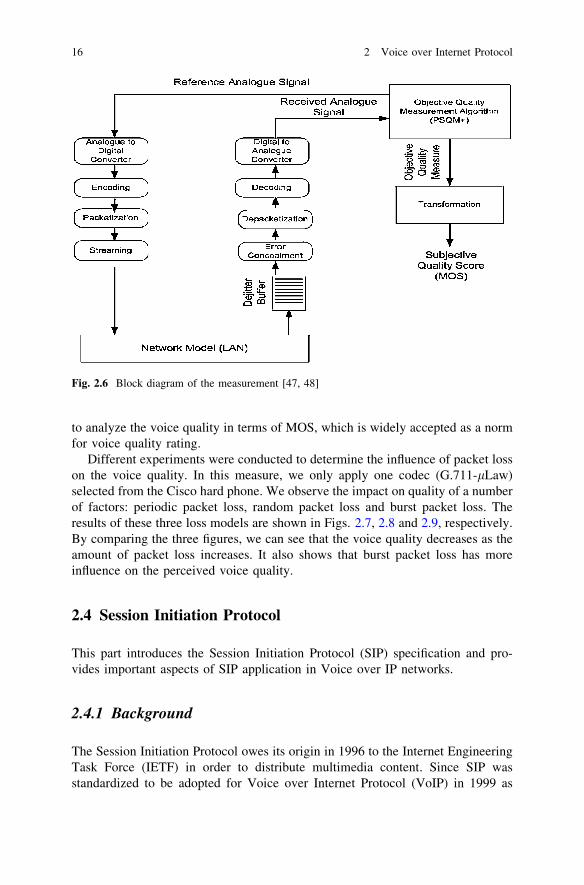
to analyze the voice quality in terms of MOS, which is widely accepted as a normfor voice quality rating.
Different experiments were conducted to determine the influence of packet losson the voice quality. In this measure, we only apply one codec (G.711-lLaw)selected from the Cisco hard phone. We observe the impact on quality of a numberof factors: periodic packet loss, random packet loss and burst packet loss. Theresults of these three loss models are shown in Figs. 2.7, 2.8 and 2.9, respectively.By comparing the three figures, we can see that the voice quality decreases as theamount of packet loss increases. It also shows that burst packet loss has moreinfluence on the perceived voice quality.
2.4 Session Initiation Protocol
This part introduces the Session Initiation Protocol (SIP) specification and pro-vides important aspects of SIP application in Voice over IP networks.
2.4.1 Background
The Session Initiation Protocol owes its origin in 1996 to the Internet EngineeringTask Force (IETF) in order to distribute multimedia content. Since SIP wasstandardized to be adopted for Voice over Internet Protocol (VoIP) in 1999 as
Fig. 2.6 Block diagram of the measurement [47, 48]
16 2 Voice over Internet Protocol

RFC2543, it has evolved significantly and now it covers a wide range of real-timecollaboration functionalities [49]. In this chapter, we will only focus on the lateststandard RFC3261.
SIP is an end-to-end, client-server session signaling protocol. It is designed toestablish presence, locate users, set up, modify and tear down voice and videosessions across the packet-switched networks. Borrowing from the ubiquitousInternet protocol, such as the hypertext transfer protocol (HTTP) and simple mailtransfer protocol (SMTP), SIP is text-encoded, programmable, and highly
Fig. 2.8 Random loss model
Fig. 2.7 Periodic loss model
2.4 Session Initiation Protocol 17

extensible [50]. Due to its simplicity and extensibility, as well as the newly createdfeatures, SIP is not limited to IP telephony. SIP messages can convey arbitrary levelof signaling payload, session description, instant messages, JPEGs, and any MIMEtype. SIP uses Session Description Protocol (SDP) [51] for media description.
2.4.2 SIP Network Elements
2.4.2.1 A. User Agent
User agents are end entities in SIP-based Networks to connect each other andnegotiate session parameters. User agents can be both hardware and software. Forexample, in the SIP-based VoIP testbed in the lab, we used a Cisco 7960 SIPphone as shown in Fig. 2.10. It usually, but not necessarily, resides on a user’scomputer in form of a user application [52]. It can also be a PSTN gateway, acellular phone, a PDA and so on.
Fig. 2.10 A Cisco 7960 SIPPhone
Fig. 2.9 Burst loss model
18 2 Voice over Internet Protocol
In terms of functionalities, a UA can be categorized into User Agent Client(UAC) or User Agent Server (UAS). UAC and UAS are logically separated butphysically combined in the same end point. UAC works on behalf of the client tooriginate the call and receive the response, whereas the UAS functions on thebehalf of the server to listen to the incoming calls and to respond to request. Forexample, in order to initiate a call session, an INVITE message is sent by thecaller’s UAC, and received by the callee’s UAS. On the other hand, in order toterminate the session, a BYE message is sent by callee’s UAC and received by thecaller’s UAS.
2.4.2.2 B. SIP Server
Based on the functionalities, SIP servers are logically classified into three com-ponents as Registrar, Proxy Server, and Redirect Server.
Registrar is one of the SIP servers used to initialize and keep record of the useragent. It accepts the REGISTER requests and maintains the information of theusers’ AoR (Address of Record) including various kinds of SIP URL addressesbinding to the same user. Registrar also indicates the current address as the firstpriority where the user wants to send the request and receive the response [53].
Proxy server plays a very important role in processing the SIP signaling mes-sages. It receives the request from the users and looks up in the location server,where all the records of the users are kept, to find the destination address. And thenthe SIP server forwards the request by interpreting, and modifying certain parts ofthe INVITE message, such as Via. Proxy servers can be classified as stateful proxyserver or stateless proxy servers.
2.4.3 SIP Messages
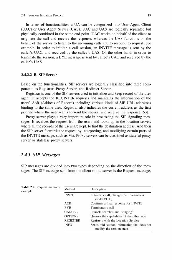
SIP messages are divided into two types depending on the direction of the mes-sages. The SIP message sent from the client to the server is the Request message,
Table 2.2 Request methodsexample
Method Description
INVITE Initiates a call, changes call parameters(re-INVITE)
ACK Confirms a final response for INVITEBYE Terminates a callCANCEL Cancels searches and ‘‘ringing’’OPTIONS Queries the capabilities of the other sideREGISTER Registers with the Location ServiceINFO Sends mid-session information that does not
modify the session state
2.4 Session Initiation Protocol 19

while that from the server to the client is the Response message. Tables 2.2 and 2.3give examples of the Request and Response SIP messages, respectively.
SIP messages consist of three main parts: start line, header, and message body.Each SIP message begins with a start line to convey the message type and theprotocol version. SIP headers are borrowed from the syntax and semantics ofHTTP header fields, to convey more message attributes. The message body can useeither Session Description Protocol (SDP) or Multipurpose Internet Mail Exten-sions (MIME). Here is an example of the INVITE message:
INVITE sip:[email protected] SIP/3.0Via: SIP/3.0/UDP 192.2.4.4:5060To: Bob \ sip:[email protected][From: Aline \ sip:[email protected] [ ;tag = 203 941 885Call-ID: [email protected]: 26 563 897 INVITEContact: \ sip:[email protected][Content-Type: application/sdpContact-Length: 142
v = 0o = Alice 53655765 2353687637 IN IP4128.3.4.5s = Call from Alicec = IN IP4 192.2.4.4M = audio 3456 RTP/AVP 0 3 4 5
Table 2.3 Response example
Type Class Description Examples
Code Meaning
Provisional 1xx In Progress 100 Trying180 Ringing
Final 2xx Success 200 OK3xx Redirection 300 Multiple choices
301 Moved permanently302 Moved temporarily
4xx Client Error 400 Bad request401 Unauthorized403 Forbidden408 Request time-out480 Temporarily unavailable481 Call/Transaction does not exist482 Loop detected
5xx Server Error 500 Server error6xx Global Failure 600 Busy everywhere
603 Decline604 Does not exist anywhere606 Not acceptable
20 2 Voice over Internet Protocol
2.4.4 SIP Transactions
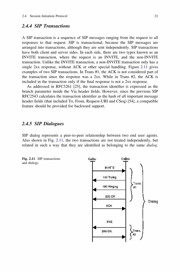
A SIP transaction is a sequence of SIP messages ranging from the request to allresponses to that request. SIP is transactional, because the SIP messages arearranged into transactions, although they are sent independently. SIP transactionshave both client and server sides. In each side, there are two types known as anINVITE transaction, where the request is an INVITE, and the non-INVITEtransaction. Unlike the INVITE transaction, a non-INVITE transaction only has asingle 2xx response, without ACK or other special handling. Figure 2.11 givesexamples of two SIP transactions. In Trans #1, the ACK is not considered part ofthe transaction since the response was a 2xx. While in Trans #2, the ACK isincluded in the transaction only if the final response is not a 2xx response.
As addressed in RFC3261 [25], the transaction identifier is expressed as thebranch parameter inside the Via header fields. However, since the previous SIPRFC2543 calculates the transaction identifier as the hash of all important messageheader fields (that included To, From, Request-URI and CSeq) [54], a compatiblefeature should be provided for backward support.
2.4.5 SIP Dialogues
SIP dialog represents a peer-to-peer relationship between two end user agents.Also shown in Fig. 2.11, the two transactions are not treated independently, butrelated in such a way that they are identified as belonging to the same dialog.
Fig. 2.11 SIP transactionsand dialogs
2.4 Session Initiation Protocol 21
Being identified by From and To tags and the Call-ID, SIP Dialogs facilitateproper sequencing and routing of messages between the user agents [25]. Also, thecommand sequence (Cseq) contains an integer and a method name. This Cseqnumber is incremented for each new request, which actually means that the CSeqnumber identifies a transaction. To some degree, a dialog is a sequence oftransactions [52].
2.4.6 Typical SIP Scenarios
To understand SIP signaling, two scenarios to illustrate the SIP message flow arepresented in the following.
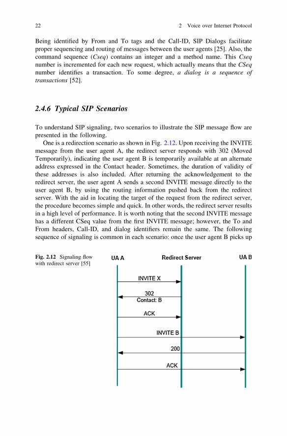
One is a redirection scenario as shown in Fig. 2.12. Upon receiving the INVITEmessage from the user agent A, the redirect server responds with 302 (MovedTemporarily), indicating the user agent B is temporarily available at an alternateaddress expressed in the Contact header. Sometimes, the duration of validity ofthese addresses is also included. After returning the acknowledgement to theredirect server, the user agent A sends a second INVITE message directly to theuser agent B, by using the routing information pushed back from the redirectserver. With the aid in locating the target of the request from the redirect server,the procedure becomes simple and quick. In other words, the redirect server resultsin a high level of performance. It is worth noting that the second INVITE messagehas a different CSeq value from the first INVITE message; however, the To andFrom headers, Call-ID, and dialog identifiers remain the same. The followingsequence of signaling is common in each scenario: once the user agent B picks up
Fig. 2.12 Signaling flowwith redirect server [55]
22 2 Voice over Internet Protocol

the phone, the 200 OK message is sent back to the user agent A, and the mediaflow is established after the user agent B receives the acknowledgement.
The other scenario, as shown in Fig. 2.13, is that the request traverses multipleproxy servers before reaching the destination. The main difference from the firstscenario is that after making the routing decision, each intermediary proxy servermodifies the INVITE message and then forwards it to the next proxy server. Theresponse routes through the same set of proxies in the reverse order.
2.5 Summary
This chapter has provided a brief overview of VoIP networks from differentperspectives. Laboratory implementation and studies on the measurement of voicequality have been discussed. The popular VoIP signaling procedure SIP has beendescribed in detail. In the next section, we will present the analytical model fordelay-throughput analysis adopted in this book.
Fig. 2.13 Signaling flow with proxy server [55]
2.4 Session Initiation Protocol 23
Related Documents