Department of Collegiate and Technical Education Chapter 2 TRANSDUCERS AND STRAIN GAUGES PREPARED BY THAURYA NAIK LECTURER/ME GPT KAMPLI

Welcome message from author
This document is posted to help you gain knowledge. Please leave a comment to let me know what you think about it! Share it to your friends and learn new things together.
Transcript
Department of Collegiate and Technical
Education
Chapter 2 TRANSDUCERS AND STRAIN GAUGES
PREPARED BY
THAURYA NAIK
LECTURER/ME
GPT KAMPLI
TRANSDUCERS
2.1 Introduction:
Sensing of input parameter is very essential in all measurement.
This is effectively done using sensors and transducers.
Definition:
Transducers are generally defined as devices that transform
values of physical quantities in the form of input signals
into corresponding electrical output signals.
The physical quantity may be heat, intensity of light, flow rate,
etc.
2
TRANSDUCERS (Cont...)
Transducer :
➢ A transducer is a device used to convert position
displacement, thermal and optical signal into electrical
quantities that may be amplified, recorded and otherwise
processed in the instrumentation system.
➢ Transducers are also known as prime sensors or pickups or
signal generators.
➢ The function of the transducer is to present the input
information into analogous form.
3
Introduction (Cont…)
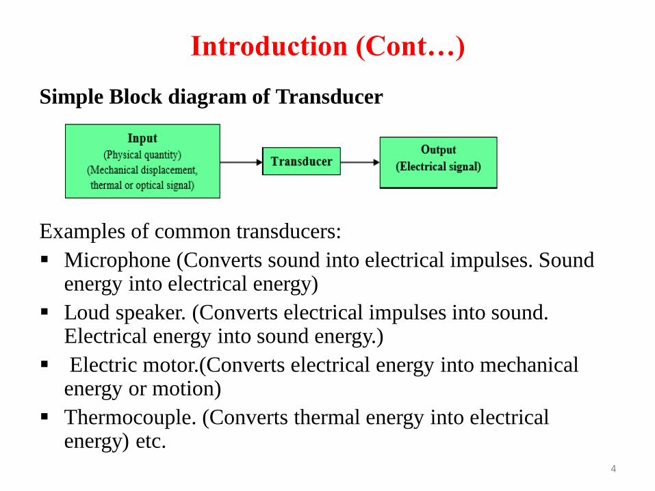
Simple Block diagram of Transducer
Examples of common transducers:
▪ Microphone (Converts sound into electrical impulses. Sound energy into electrical energy)
▪ Loud speaker. (Converts electrical impulses into sound. Electrical energy into sound energy.)
▪ Electric motor.(Converts electrical energy into mechanical energy or motion)
▪ Thermocouple. (Converts thermal energy into electrical energy) etc.
4
Characteristics of Transducers
The characteristics of transducers are as follows:
▪ It should be compact, small in size and less weight
▪ It should have exceptional reliability
▪ It should high sensitivity
▪ It should maintain stability with environmental changes
▪ It should develop linear relationship between input and output
▪ It should be available at lowest possible cost and ease of
producing, fabricating it.
5
Requirements of Transducers1) Nature of measurement to be made
2) Mechanical input characteristics
a. Linearity
b. Mechanical hysteresis
c. Viscous flow or Creep
3) Loading effect of the transducers
4) Environmental factors (Ability to withstand environmental
conditions).
5) Capability of the transducer
6) Compatibility of the transducer and measuring system.
6
Requirements of Transducers (Cont…)
7) Economical factors or considerations
8) Smaller in size and weight.
9) High sensitivity.
10) Low cost.
Nature of measurement to be made:
The measurement parameters are either steady state, transient or
dynamic
Ex: A strain gauge located on the structured member of an
aircraft would indicate steady loading on smooth flight,
dynamic loading and transient loading during landing.
7
Requirements of Transducers (Cont…)
Mechanical input characteristics:
For static measurements, it is very important that transducer must
have linear relationship between inputs and output.
Example : Mechanical hysteresis in transducers like springs,
pressure capsule etc
Factors like friction, backlash, loose screws etc., are
responsible for hysteresis in the transducer.
8
Requirements of Transducers (Cont…)Loading Effect of transducer:
If the attachments or installation of transducer in anyway affect or changes the value of parameters being measured, errors may be introduced.
Ex: If the mass of the thermocouple junction is too large, it physically affects the process by absorbing the heat in the system.
Environmental considerations :
The following environmental factors affect the performance of transducer
a) Temperature
b) Shocks
c) Vibration
d) Electromagnetic interference. 9
Requirements of Transducers (Cont…)
Transducer Capability:
▪ Transducer capabilities should be investigated to determine the
effect of overheating, over range and power dissipation rating.
▪ When sensing the input signal, the output power of the
transducer must not exceed the specified maximum power.
▪ Some factors involved in the selection of transducers are cost,
Basic simplicity, reliability and low maintenance.
10
Factors To Be Considered While Selecting
Transducer
• It should have high input impedance and low output
impedance, to avoid loading effect.
• It should have good resolution over is entire selected range.
• It must be highly sensitive to desired signal and insensitive to
unwanted signal.
• Preferably small in size.
• It should be able to work in corrosive environment.
• It should be able to withstand pressure, shocks, vibrations etc..
• It must have high degree of accuracy and repeatability.
• Selected transducer must be free from errors.
11
Classification Of Transducers
1. Based on the physical phenomenon,
• Primary transducer
• Secondary transducer
2. Based on the power type
• Active transducer
• Passive transducer
3. Based on the type of output the classification of
transducers are made,
• Analog transducer
• Digital transducer
12
Classification Of Transducers (Cont…)
4. Based on the electrical phenomenon
• Resistive transducer
• Capacitive transducer
• Inductive transducer
• Photoelectric transducer
• z Thermoelectric transducer
• Piezoelectric transducer
• Photovoltaic transducer
5. Based on the non-electrical phenomenon
• Linear displacement
• Rotary displacement
6. Based on the transduction phenomenon
• Transducer
• Inverse transducer
13
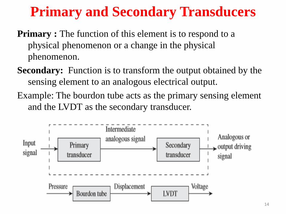
Primary and Secondary Transducers
Primary : The function of this element is to respond to a
physical phenomenon or a change in the physical
phenomenon.
Secondary: Function is to transform the output obtained by the
sensing element to an analogous electrical output.
Example: The bourdon tube acts as the primary sensing element
and the LVDT as the secondary transducer.
14
Active transducer and Passive transducer
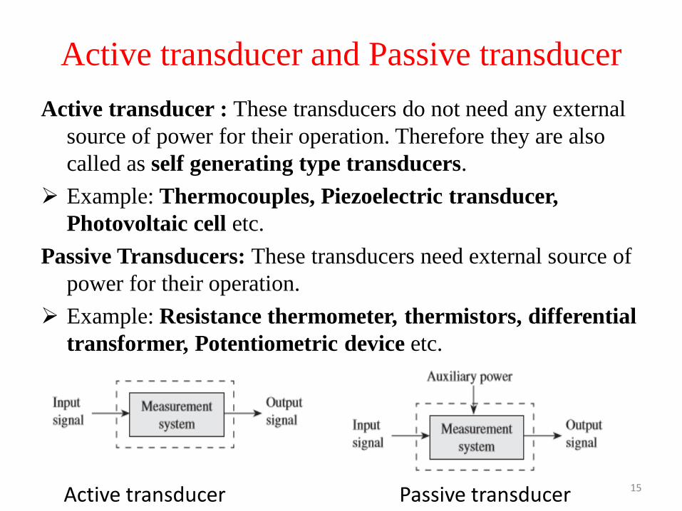
Active transducer : These transducers do not need any external
source of power for their operation. Therefore they are also
called as self generating type transducers.
➢ Example: Thermocouples, Piezoelectric transducer,
Photovoltaic cell etc.
Passive Transducers: These transducers need external source of
power for their operation.
➢ Example: Resistance thermometer, thermistors, differential
transformer, Potentiometric device etc.
Active transducer Passive transducer 15
Analog and Digital transducer
Analog Transducer: These transducers convert the input
phenomenon into an analogous output which is a continuous
function of time.
➢ Example: Strain gauge, Thermocouple, Thermistors, LVDT
etc.
Digital transducer: These transducers convert the input
phenomenon into an electrical output which may be in the
form of pulse.
➢ Examples of Digital Transducer Applications as Turbine meter
used in for flow measurement.
16
Direct and Inverse Transducers
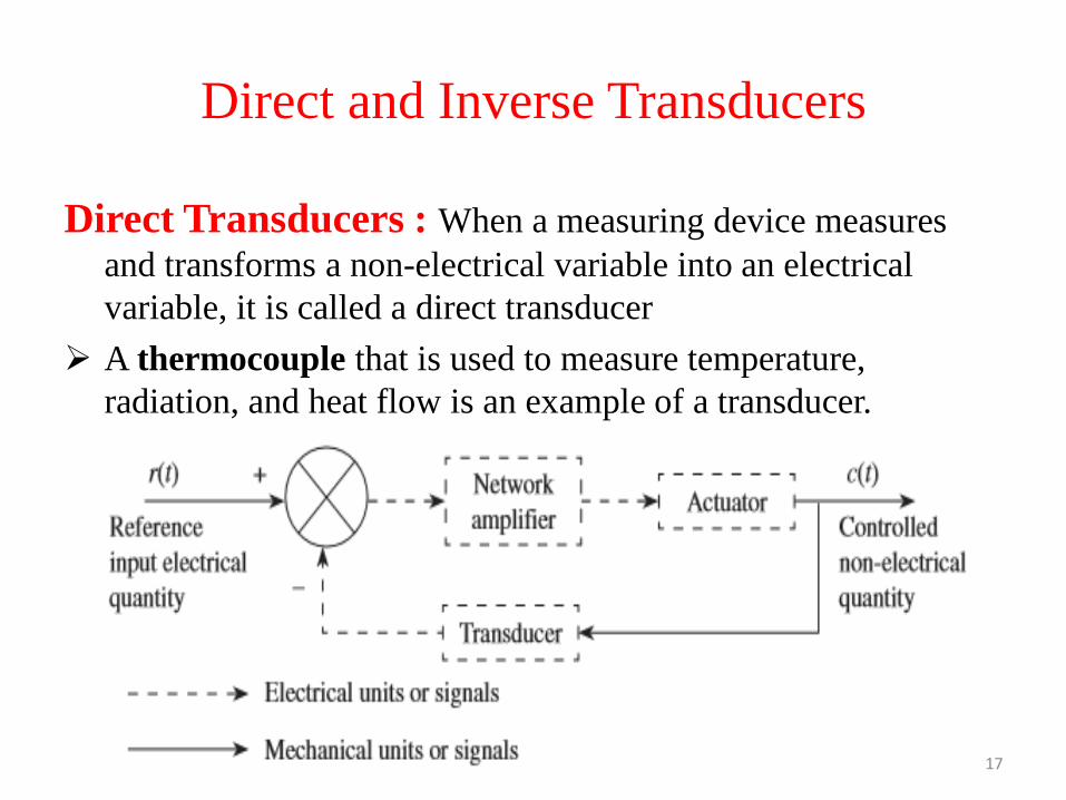
Direct Transducers : When a measuring device measures
and transforms a non-electrical variable into an electrical
variable, it is called a direct transducer
➢ A thermocouple that is used to measure temperature,
radiation, and heat flow is an example of a transducer.
17
Direct and Inverse Transducers (Cont…)
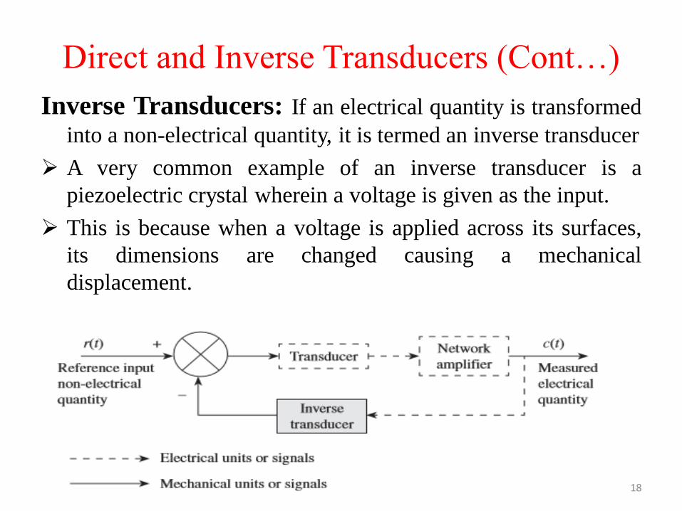
Inverse Transducers: If an electrical quantity is transformed
into a non-electrical quantity, it is termed an inverse transducer
➢ A very common example of an inverse transducer is a
piezoelectric crystal wherein a voltage is given as the input.
➢ This is because when a voltage is applied across its surfaces,
its dimensions are changed causing a mechanical
displacement.
18
Actuating Mechanisms
Actuator:An actuator is a device that converts energy into motion.
Therefore, it is a specific type of a transducer.
Actuating mechanisms used in some devices are
1. Bellows
2. Diaphragms- Flat, Corrugated and Capsule.
3. Bourdon tubes- Circular and Twisted.
4. Vanes
5. Rectilinear motions.
6. Shaft rotations – Pivot Torque and Unrestrained.
7. Proving rings.
8. Cantilever beams.
9. Beam elongation.
10. Seismic mass and springs and others.
19
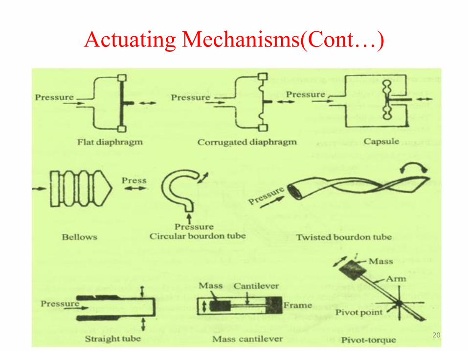
Actuating Mechanisms(Cont…)
20
Voltage and current generating analog
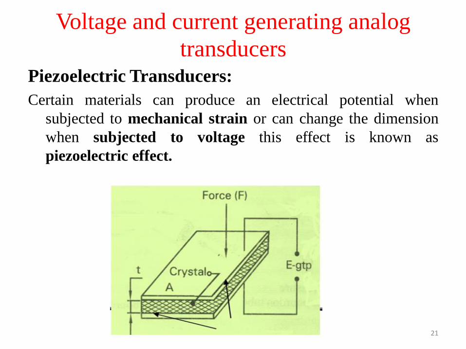
transducersPiezoelectric Transducers:
Certain materials can produce an electrical potential when
subjected to mechanical strain or can change the dimension
when subjected to voltage this effect is known as
piezoelectric effect.
21
Piezoelectric Transducers (Cont…)
• When force is applied to the plate, a stress will be produced in
the crystal and a corresponding deformation with certain
crystals. This deformation produces a potential difference at
the surface of the crystal, and this effect is known as
piezoelectric effect.
• The induced charge on the crystal is proportional to the
impressed force.
• E=gtp
Where g=Voltage sensitivity
t=Crystal thickness
p=Pressure
The induced charge will be given by the relation.
22
Piezoelectric Transducers (Cont…)
The induced charge will be given by the relation.
Q=k F
Where, Q (charge) is in Coulombs,
F is in Newton and
‘k’ is Piezoelectric constant
23

Characteristics of Piezoelectric Materials
Characteristics of Piezoelectric Materials
Rochelle salt: Rochelle salt gives the highest output but needs
protection from moisture in the air and limited to use up to
45OC only.
Quartz: Quartz is the most stable material of all, but has a very
low output. Because of its high stability, quartz is commonly
used for stabilizing the electronic oscillators.
Barium titrate: It is a polycrystalline material and is used to
produce photoelectric effect. It may be formed into variety of
sizes and shapes and used for high temperature range.
24
Two Coil Transducer
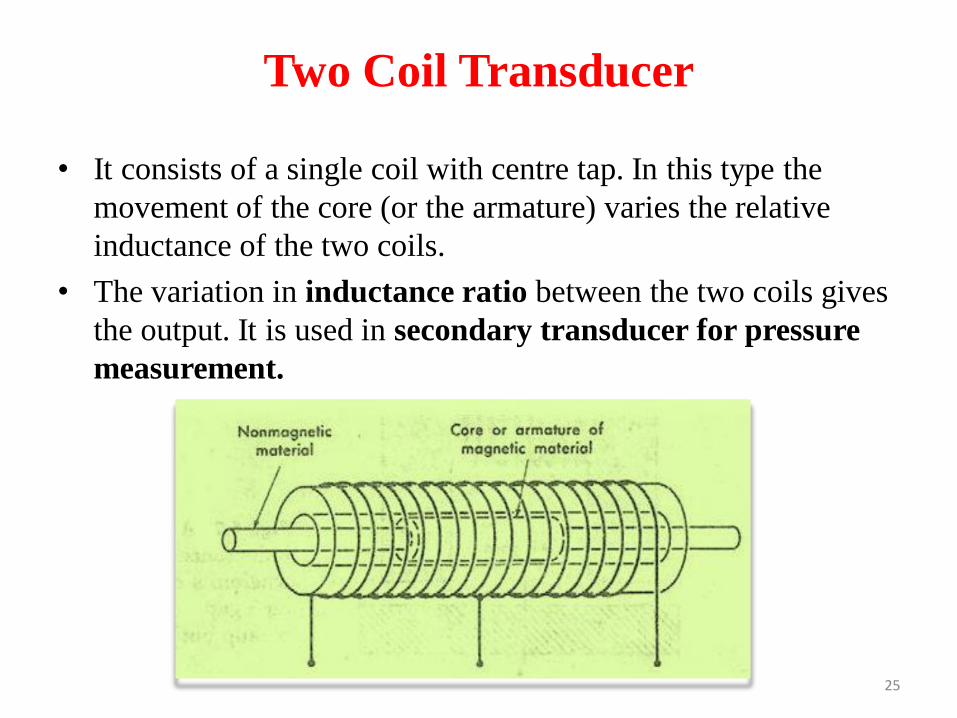
• It consists of a single coil with centre tap. In this type the
movement of the core (or the armature) varies the relative
inductance of the two coils.
• The variation in inductance ratio between the two coils gives
the output. It is used in secondary transducer for pressure
measurement.
25
STRAIN GAUGES
Introduction:
▪ It is not possible (currently) to measure stress directly in a
structure. However, it is possible to measure strain since it is
based on displacement.
▪ Strain gauges are constructed from a single wire that is wound
back and forth. The gauge is attached to the surface of an
object with wires in the direction where the strain is to be
measured.
▪ The electrical resistance in the wires change when they are
elongated. Thus, the voltage change in the wires can be
collaborated to the change in strain.
26
STRAIN GAUGES (Cont…)
Definition:
A strain gauge is a device used to measure strain on an object.
Purposes:
Strain gauges are used for either of the two purposes.
1. To determine the state of strain existing at a point on a
loaded member for the purpose of stress analysis.
2. To act as a strain sensitive transducer element calibrated in-
terms of quantities such as force, pressure, displacement,
acceleration or for the purpose of measuring the magnitude
of the input quantity.
27
STRAIN GAUGES (Cont…)
Metals Used In Making Strain Gauges:
The strain gauges are made with the following metals.
1. Constantan
2. Nichrome
3. Dynalloy
4. Platinum alloy
5. Copper Nickel
6. Nickel Chrome
7. Nickel Iron
8. Modified Nickel Chrome
9. Platinum Tungsten28
STRAIN GAUGES (Cont…)Classification:Strain gauges can be classified as follows.
A. Mechanical strain gauges
B. Optical strain gauges
C. Electrical strain gauges
A. Resistance strain gauges
A. Bonded type
B. Un-bonded type
C. Bonded wire type
D. Bonded foil type
E. Semiconductor gauges
B. Capacitive gauges
C. Inductive gauges
D. Piezoelectric gauges29
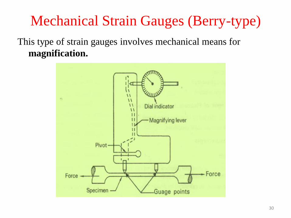
Mechanical Strain Gauges (Berry-type)
This type of strain gauges involves mechanical means for
magnification.
30
Mechanical Strain Gauges (Berry-type)
• It consists of two gauge points which will be seated on the
specimen whose strain is to be measured.
• One gauge point is fixed while the second gauge point is
connected to a magnifying lever, which in turn gives the input
to a dial indicator.
• The lever magnifies the displacement and is indicated directly
on the calibrated dial indicator.
• This displacement is used to calculate the strain value.
• This is used for structural applications in civil engineering for
long gauge lengths of up to 200 mm.
31
Mechanical Strain Gauges (Berry-type)(Cont..)
Advantages
• It has a self contained magnification system.
• No auxiliary equipment is needed as in the case of electrical strain gauges.
Disadvantages
• Limited only to static tests.
• The high inertia of the gauge makes it unsuitable for dynamic measurements and varying strains.
– The response of the system is slow and also there is no method of recording the readings automatically.
• There should be sufficient surface area on the test specimen and clearance above it in order to accommodate the gauge together with its mountings.
32
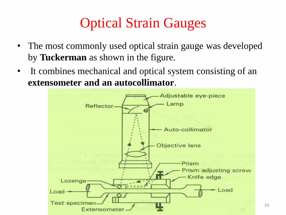
Optical Strain Gauges
• The most commonly used optical strain gauge was developed
by Tuckerman as shown in the figure.
• It combines mechanical and optical system consisting of an
extensometer and an autocollimator.
33
Optical Strain Gauges(Cont…)
• The nominal length of the gauge is the distance from a knife
edge to the point of contact of the lozenge. The lozenge acts
like a mirror.
• The function of the autocollimator is to send parallel rays of
light and receive back the reflected light beam from the
lozenge on the optical system.
• The relative movement of the reflected light as viewed through
the eye-piece of the autocollimator is calibrated to measure
the strain directly.
34
Optical Strain Gauges(Cont…)
• This gauge can be used for dynamic measurements of up to 40
Hz using a photographic recorder, and strains as small as
2µm/m can be resolved. Gauge lengths may vary from 6 mm
to 250 mm.
• The position of autocollimator need not be fixed relative to the
extensometer, and reading can be taken by holding the
autocollimator in hand.
35
Optical Strain Gauges(Cont…)
Advantage :
• The position of autocollimator need not be fixed relative to the
extensometer, and reading can be taken by holding the
autocollimator in hand.
Disadvantages:
• Limited only for static measurements.
• Large gauge lengths are required.
• Cannot be used where large strain gradients are encountered.
36

Mounting Of Strain Gauges
• The surface on which the strain gauge has to be mounted must
be properly cleaned by an emery cloth and bare base material
must be exposed.
• Various traces of grease or oil etc., must be removed by using
solvent like acetone.
• The surface of the strain gauges coming in contact with the test
item should also be free from grease etc.
• Sufficient quantity of cement is applied to the cleaned surface
37
Mounting Of Strain Gauges(Cont…)
• The gauges are then allowed to set for at least 8 or 10 hours
before using it.
• After the cement is fully cured the electrical continuity of the
grid must be checked by ohm-meter and the electrical leads
may be welded.
38

Problems Associated With Strain Gauge
Installations
The problems associated with strain gauge generally fall in to the
following three categories.
• Temperature effects
• Moisture absorption
• Wiring problems
39
Strain Gauge Rosettes
Introduction:
➢ An arrangement of two or more closely positioned gauge
grids, separately oriented to measure the normal strains
along different directions in the underlying surface of the test
part.
➢ As the principal directions unknown, three independent strain
measurements (in different directions) are required to
determine the principal strains and stresses.
➢ And even when the principal directions are known in advance,
two independent strain measurements are needed to obtain
the principal strains and stresses.
40
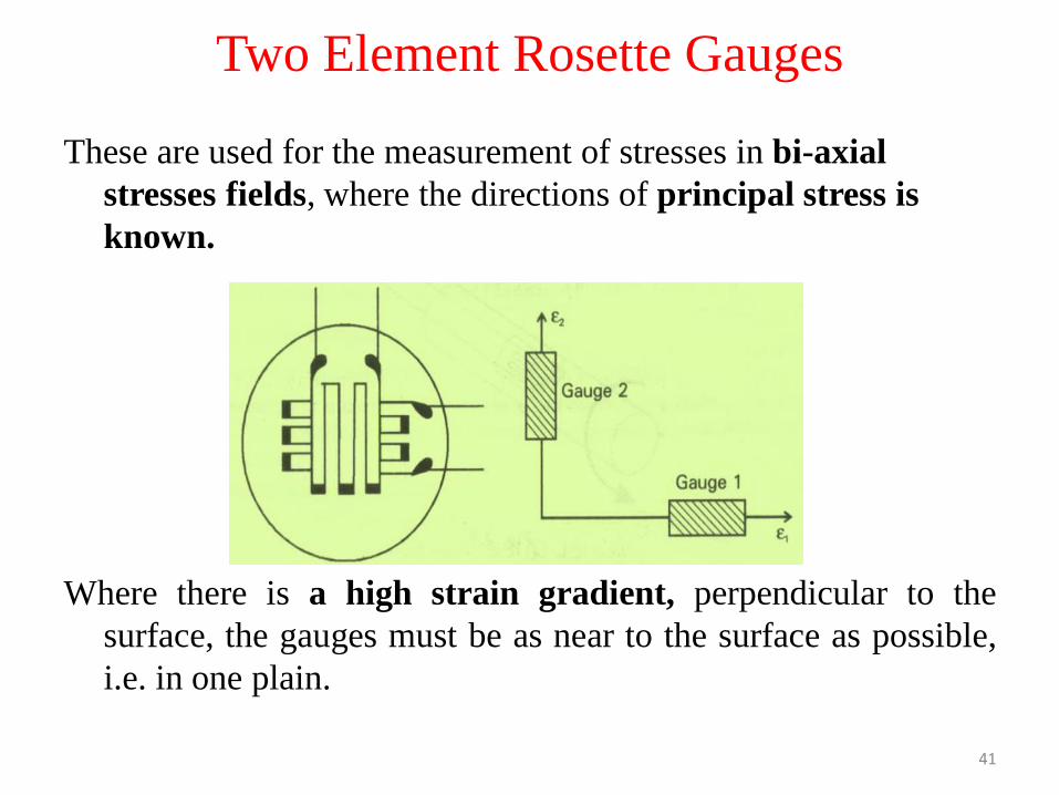
Two Element Rosette Gauges
These are used for the measurement of stresses in bi-axial
stresses fields, where the directions of principal stress is
known.
Where there is a high strain gradient, perpendicular to the
surface, the gauges must be as near to the surface as possible,
i.e. in one plain.
41
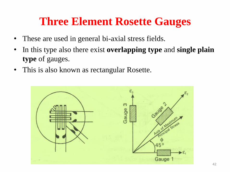
Three Element Rosette Gauges
• These are used in general bi-axial stress fields.
• In this type also there exist overlapping type and single plain
type of gauges.
• This is also known as rectangular Rosette.
42
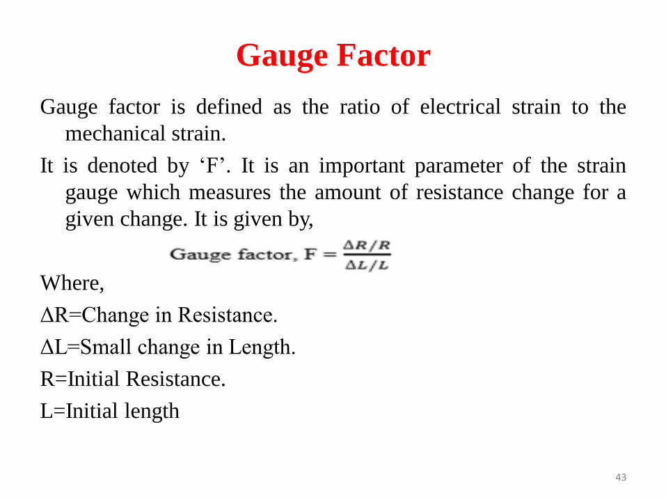
Gauge Factor
Gauge factor is defined as the ratio of electrical strain to the
mechanical strain.
It is denoted by ‘F’. It is an important parameter of the strain
gauge which measures the amount of resistance change for a
given change. It is given by,
Where,
ΔR=Change in Resistance.
ΔL=Small change in Length.
R=Initial Resistance.
L=Initial length
43
Gauge Factor(Cont…)
• Higher the gauge factor of strain gauge, the more sensitivity of
the gauge and greater electrical output for indication and
recording purpose.
• All the efforts is to be made to develop a strain gauge having
high gauge factor.
44
Related Documents