11 CHAPTER 2 THEORY OF STEPPER MOTOR 2.1 INTRODUCTION Stepper motor is a special type of electric motor that moves in precisely defined increments of rotor position (Steps). The size of the increment is measured in degrees and can vary depending on the application. Due to precise control, stepper motors are commonly used in medical, satellites, robotic and control applications. There are several features common to all stepper motors that make them ideally suited for these types of applications. They are as under High accuracy: Operate under open loop Reliability: Stepper motors are brushless. Load independent: Stepper motors rotate at a set speed under different load, provided the rated torque is maintained. Holding torque: For each and every step, the motor holds its position without brakes. Stepper motor requires sequencers and driver to operate. Sequencer generates sequence for switching which determines the direction of rotation and mode of operation. Driver is required to change the flux direction in the phase windings. The block diagram of stepper motor system is shown in Figure 2.1.

Welcome message from author
This document is posted to help you gain knowledge. Please leave a comment to let me know what you think about it! Share it to your friends and learn new things together.
Transcript

11
CHAPTER 2
THEORY OF STEPPER MOTOR
2.1 INTRODUCTION
Stepper motor is a special type of electric motor that moves in
precisely defined increments of rotor position (Steps). The size of the increment
is measured in degrees and can vary depending on the application. Due to precise
control, stepper motors are commonly used in medical, satellites, robotic and
control applications. There are several features common to all stepper motors that
make them ideally suited for these types of applications. They are as under
High accuracy: Operate under open loop
Reliability: Stepper motors are brushless.
Load independent: Stepper motors rotate at a set speed under
different load, provided the rated torque is maintained.
Holding torque: For each and every step, the motor holds its
position without brakes.
Stepper motor requires sequencers and driver to operate. Sequencer
generates sequence for switching which determines the direction of rotation and
mode of operation. Driver is required to change the flux direction in the phase
windings. The block diagram of stepper motor system is shown in Figure 2.1.
12
Figure 2.1 Block diagram of stepper motor system
2.2 TYPES OF STEPPER MOTORS
It can be classified into several types according to machine structure
and principle of operation as explained by Kenjo (1984). Basically there are three
types
1. Variable Reluctance Motor (VRM)
2. Permanent Magnet Stepper Motor (PMSM)
3. Hybrid Stepper Motor (HSM)
2.2.1 Variable Reluctance Motor
It consists of a soft iron multi-toothed rotor and a wound stator. When
the stator windings are energized with DC current, the poles become
magnetized. Rotation occurs when the rotor teeth are attracted to the energized
stator poles. Both the stator and rotor materials must have high permeability and
be capable of allowing high magnetic flux to pass through even if a low magneto
motive force is applied. When the rotor teeth are directly lined up with the stator
poles, the rotor is in a position of minimum reluctance to the magnetic flux.
Driver Circuit Sequencer
Stepper Motor
Power Supply

13
A rotor step takes place when one stator phase is deenergized and
the next phase in sequence is energized, thus creating a new position of
minimum reluctance for the rotor as explained by Kenjo (1984). Cross-section of
variable reluctance motor is shown in Figure 2.2.
Figure 2.2 Cross-section of variable reluctance motor
2.2.2 Permanent Magnet Stepper Motor
A stepper motor using a permanent magnet in the rotor is called a
PMSM. The rotor no longer has teeth as with the VRM. Instead the rotor is
magnetized with alternating north and south poles situated in a straight line
parallel to the rotor shaft. These magnetized rotor poles provide an increased
magnetic flux intensity and, because of this the PM motor exhibits improved
torque characteristics when compared with the VRM type. An elementary PM
motor is shown in Figure 2.3 which employs a cylindrical permanent magnet as the
rotor and possesses four poles in its stator. Two overlapping windings are wound
as one winding on poles 1 and 3 and these two windings are separated from
each other at terminals to keep them as independent windings. The same is true
for poles 2 and 4. The terminals marked Ca or Cb denotes
connected to the positive terminal of the power supply as explained by Kenjo
(1984).

14
When the windings are excited in the sequence A - B - A1 - B1 --- the
rotor will be driven in a clockwise direction. The step length is 900 in this
machine. If the number of stator teeth and magnetic poles on the rotor are both
doubled, a two-phase motor with a step length of 450 will be realized.
Figure 2.3 Cross-section of permanent magnet stepper motor
2.2.3 Hybrid Stepper Motor
is derived from the fact that motor is operated with
the combined principles of the permanent magnet and variable reluctance motors
in order to achieve small step length and high torque in spite of motor size.
Standard HSM have 50 rotor teeth and rotate at 1.8 degree per step. Figures 2.4
& 2.5 show a cross section and cut view of two phase HSM. The windings are
placed on the stator poles and a PM is mounted on the rotor. The important
feature of the HSM is its rotor structure. A cylindrical or disk-shaped magnet lies
in the rotor core. Stator and rotor end-caps are toothed. The coil in pole 1 and pole
3 is connected in series consisting of phase A and poles 2 and 4 are for phase
B. If stator phase A is excited pole 1 acquires north polarity while pole 2
acquires south south pole while pole 3 aligns
north pole.

15
Figure 2.4 Cross-section of HSM
Figure 2.5 Cut view of HSM
When the excitation is shifted from phase A to phase B, in which
case the stator pole 2 becomes north pole and stator pole 4 becomes south
pole, it would cause the rotor to turn 900 in the clockwise direction. Again phase
A is excited with pole 1 as south pole and pole 3 as north pole causing the
rotor to move 900 in the clockwise direction.
Rotor -1
Shaft
Rotor -2
Stator -1
Coil Winding
End cap End cap
Bearing
Permanent magnet
16
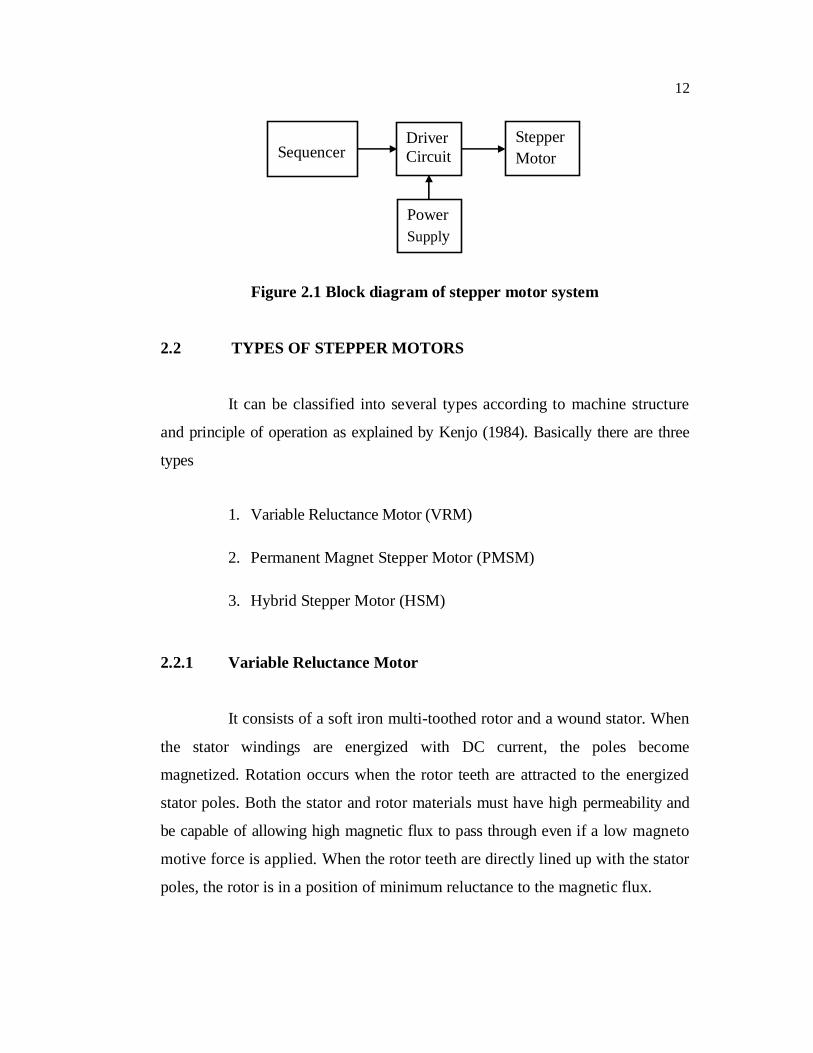
If excitation is removed from phase A and phase B is excited, then
pole 2 produces south pole and pole 4 produces north pole resulting in rotor
movement of 900 in the clockwise direction. A complete cycle of excitation for the
HSM consists of four states and produces four steps of rotor movement. The
excitation state is the same before and after these four steps and hence the
alignment of stator/rotor teeth occurs under the same stator poles as explained
by Kenjo (1984). The step length for a HSM and angle through which the rotor
moves for each step pulse is known as step angle and is calculated by
Step length = 90o/Nr (2.1)
Step angle is calculated using the formula
(2.2)
Where - Step angle in degrees - Number of stator teeth - Number of rotor teeth - Number of phases
Mechanical angle represents the step angle of the step. In the full step
mode of a 1.8° motor, the mechanical angle is 1.8°. In the 10 micro step mode of
a 1.8° motor, the mechanical angle is 0.18º. An electrical angle is defined as
360° divided by the number of mechanical phases and the number of micro step.
In the full step mode of a 1.8° motor, the electrical angle is 90°. In the 10 micro
step excitation of a 1.8° motor, the electrical angle is 9º.
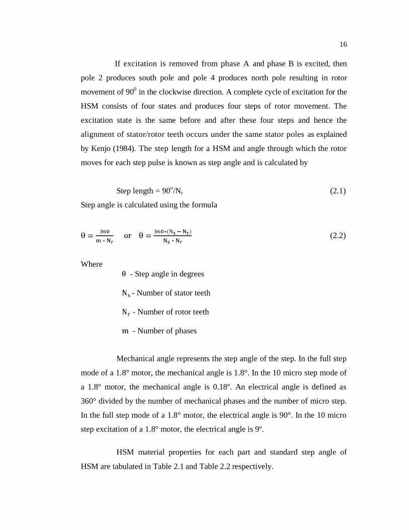
HSM material properties for each part and standard step angle of
HSM are tabulated in Table 2.1 and Table 2.2 respectively.
17
Table 2.1 Material properties of HSM
S.No Motor Part Material
1. Shaft Non-Magnetic material
2. Magnet Neodymium Iron Boron (NdFe) /
Samarium Cobalt (SMCO5)
3. Rotor core Steel sheet
4. Stator core Steel sheet
5. Coil Copper
Table 2.2 Standard step angle of HSM
Step angle Steps per revolution
0.9º 400
1.8 º 200
3.6 º 100
7.2 º 50
15 º 24

18
Advantages and disadvantages of HSM are discussed by Acarnely
(2002) and in a nutshell, they are as here below
a. Advantages
1. Step angle error is very small and non-cumulative.
2. Rapid response to starting, stopping and reversing.
3. Brushless design for reliability and simplicity.
4. High torque per package size.
5. Holding torque at standstill.
6. Can be stalled repeatedly and indefinitely without damage.
7. No extra feedback components required (encoders).
b. Disadvantages
1. Resonance
2. Vibration
3. Torque ripple
2.3 COMPARISON OF STEPPER MOTOR TYPES
The choice of the type of the stepper motor depends on the application.
Selection of stepper motor depends on torque requirements, step angle and control
technique.

19
The complexity of the controller circuits are explained detail by Athani
(2005). Comparisons based on motor advantages and disadvantages, motor
characteristics and different phases are tabulated in Tables (2.3 - 2.5).
Table 2.3 Comparison based on motor advantages and disadvantages
Motor type Advantages Disadvantages
Variable
Reluctance
Motor
1. Robust No magnet
2. Smooth movement due to
no cogging torque.
3. High stepping rate and
speed slewing capability.
1. Vibrations
2. Complex circuit for
control
3. No smaller step angle
4. No detent torque.
Permanent
Magnet
Stepper Motor
1. Detent torque
2. Higher holding torque
3. Better damping
1. Bigger step angle
2. Fixed rated torque.
3. Limited power
output and size
Hybrid
Stepper Motor
1. Detent torque
2. No cumulative position
error
3. Smaller step angle
4. Operate in open loop
1. Resonance
2. Vibration

20
Table 2.4 Comparison based on motor characteristics
Specifications Motor types
VRM PMSM HSM
Step angle 0.66 º 30º 3.75 º 45º 0.45º 5º
Phases 3,4,5 2,4 2,5
Drive type Unipolar Unipolar/Bipolar Bipolar
Rotor inertia Low High Medium
Table 2.5 Comparison based on different phase properties
Type of Phases Properties
2 phase
1. Simple driver circuit with low heat dissipation.
2. Less step error compared to other phases.
3. Higher accuracy due to more number of stator
Poles.
3 phase
1. Torque ripple is more.
2. Poor peak torque ratio.
3. Power transistors are less.
4 phase 1. Low torque ripple.
2. Good peak torque ratio.
5 phase 1. Lower torque ripple.
2. More expensive controller.

21
The increased number of phases requires complicated control circuits,
which provide better dynamics and considerable increase in the number of steps.
2.4 SELECTION OF MOTOR
Stepper motor can be selected based on the following specifications as
explained in Athani (2005)
1. Electrical specifications include number of phases, step angle,
winding voltage, winding resistance/ inductance, holding torque,
pull-out torque, maximum slew rate, positional accuracy,
temperature rise and power supply & drive circuits.
2. Mechanical specifications includes shaft length & shape, motor
length, shape of flange face, lead wire length and connector type
2.5 DIFFERENT MODES OF EXCITATION
Different types of excitation schemes of the stepper motor are
explained by Kenjo (1984) and they are
1. Full step
2. Half step
3. Micro step
According to the specified pattern, the phase voltages are switched
with positive and negative polarity. The motor shaft moves through an
appropriate fraction of step angle for each switching. Phase excitation scheme
plays a vital role in the performance of a stepper motor. The most important
aspect is to decide the step angle of the motor for a particular application.
Standard step angles are tabulated in Table 2.4.
22
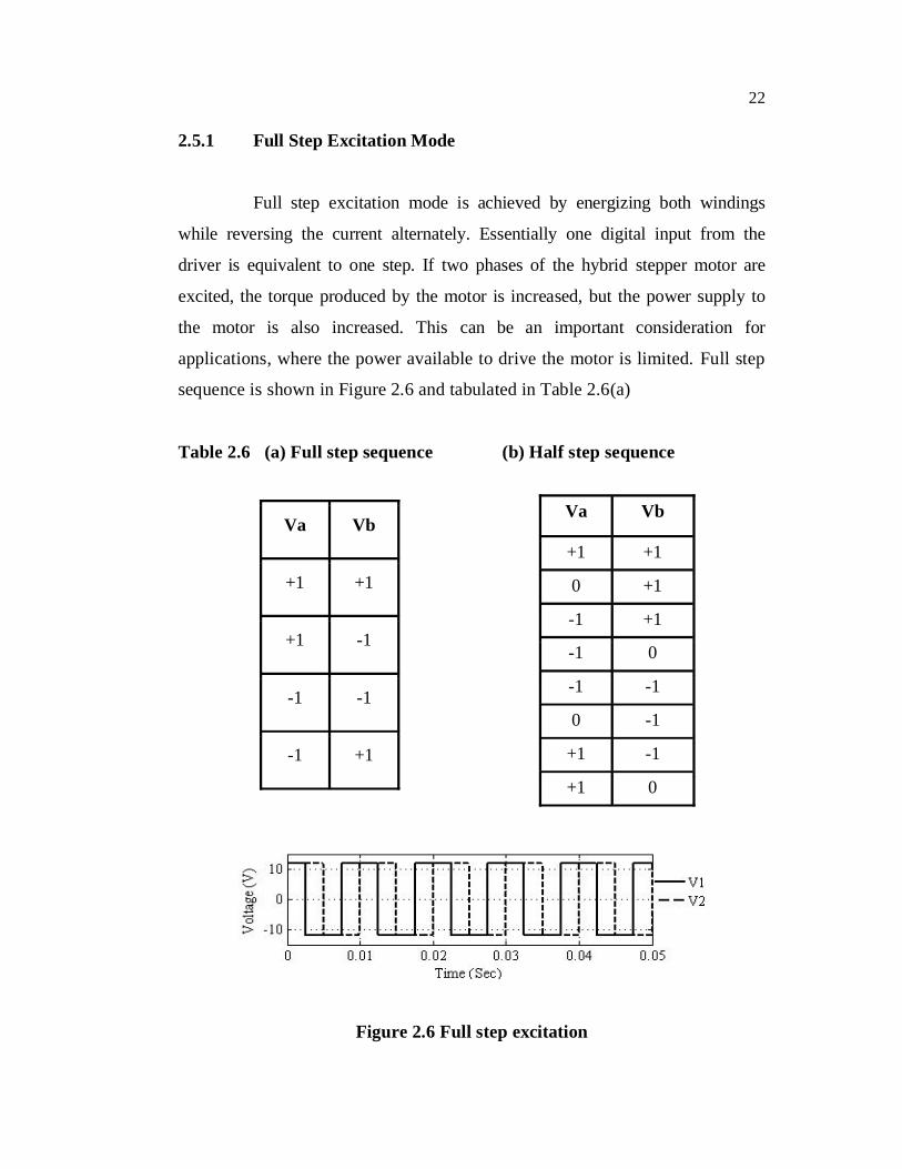
2.5.1 Full Step Excitation Mode
Full step excitation mode is achieved by energizing both windings
while reversing the current alternately. Essentially one digital input from the
driver is equivalent to one step. If two phases of the hybrid stepper motor are
excited, the torque produced by the motor is increased, but the power supply to
the motor is also increased. This can be an important consideration for
applications, where the power available to drive the motor is limited. Full step
sequence is shown in Figure 2.6 and tabulated in Table 2.6(a)
Table 2.6 (a) Full step sequence (b) Half step sequence
Figure 2.6 Full step excitation
Va Vb
+1 +1
0 +1
-1 +1
-1 0
-1 -1
0 -1
+1 -1
+1 0
Va Vb
+1 +1
+1 -1
-1 -1
-1 +1

23
2.5.2 Half Step Excitation Mode
In half step mode, the drive alternates between two phases ON and a
single phase ON . Half step sequence is shown in Figure 2.7 and tabulated in
Table. 2.6 (b). This increases the angular resolution, but the motor also has less
torque (approx 70%) at the half step position (where only a single phase is ON).
This may be mitigated by increasing the current in the active winding. The
advantage of half step is that it reduces the vibration.
Figure 2.7 Half step excitation
2.5.3 Micro Step Excitation Mode
The full step length of a stepper motor can be divided into smaller
increments of rotor motion known as micro step by partially exciting several
phase windings and micro step sequence is shown in Figure 2.8.
Figure 2.8 Micro step excitation

24
Micro step is typically used in applications that require accurate
positioning and a fine resolution over a wide range of speeds. The major
disadvantage of the micro step drive is the cost of implementation due to the need
for partial excitation of the motor windings at different current levels. The merits
as below
1. Micro step is a way of moving the stator flux of a stepper motor
more smoothly than in full or half step drive modes.
2. Less vibration making noiseless step.
3. Makes smaller step angles and hence better positioning is
possible.
4. In many applications micro step increases system performance.
5. Micro step diminish the oscillation.
2.6 TYPES OF DRIVERS
The main function of the driver circuit is to change the current and
flux direction in the phase windings. Driving a controllable amount of current
through the windings and thereby enabling maintain of short current rise and fall
time is good for high speed performance. The direction change is done by changing
the current direction, and this may be done in two different ways using a unipolar
or a bipolar drive as explained by Acarnely (2002).
2.6.1 Unipolar Driver
Winding has three leads each at the end and one in the middle. Half
of the winding only is used in motor operation at any instant of time. To change

25
the direction of rotation, end leads are chosen and the current flows in the same
direction. Unipolar winding driver circuit is simple and shown in Figure 2.9.
Figure 2.9 Unipolar winding
2.6.2 Bipolar Driver
In bipolar winding current flows in both directions as shown in Figure
2.10. Unipolar winding can be configured into bipolar if the centre lead is
ignored. Bipolar drives are most widely used drives for industrial applications.
winding is changed by shifting the voltage polarity across the winding terminal.
To change polarity, a total of four switches are needed forming an H-bridge.
The bipolar drive method requires one winding per phase. The motor
winding is fully energized by turning on one set (top and bottom) of the switching
transistors. Comparison between different drivers is tabulated in Table 2.7.
Figure 2.10 Bipolar winding

26
Table 2.7 Comparison between drivers
Unipolar driver Bipolar driver
Winding with a center tap, or two
separate windings per phase
One winding per phase
Two switches per phase Four switches per phase, in
the form of an H-bridge
Utilizes only half the available
copper volume of winding
Motor winding is fully
energized
Incurs twice the loss of a bipolar
drive at the same output power
Loss is minimum compared
to unipolar drive
2.7 CHARACTERISTICS OF STEPPER MOTOR
The construction features between the various types of SM are
different, but their behaviors are similar. Some additional characteristic details
about HSM are given below for detailed investigation as explained by Kenjo
(1984).
2.7.1 Static Characteristics
1) Torque Angle curve: The torque increases, almost sinusoidal
with angle from equilibrium position as shown in Figure 2.11.
S is the step angle (deg) and M is the maximum angle.
2) Holding torque (TH): It is the maximum load torque which the
energized step per motor can withstand without slip from position.

27
3) Detent torque (TD): It is the maximum load torque which an
unenergized step per motor can withstand without slipping and is
also known as cogging torque. It is due to residual magnetism and
about 5 -10% of holding torque. Detent torque is typically fourth
harmonic torque as shown in Figure 2.12.
Figure 2.11 Torque - angle curve of stepper motor
Figure 2.12 Torque and detent torque profiles of stepper motor
Motor Torque
Detent Torque

28
2.7.2 Dynamic Characteristics of Stepper Motor
1. Torque Vs Speed characteristics
Torque versus speed relationship of a stepper motor is shown in
Figure 2.13. The two curves are the pull-in torque and the pull-out torque curve
and intermediately pull-out region is called the slewing curve.
Figure 2.13 Torque Vs Speed curves of stepper motor
The pull-out torque versus speed curve represents the maximum
friction-torque load that a stepping motor can drive before losing synchronism
at a specified stepping rate with the magnetic field and motor stall. The pull-in
torque versus speed curve represents the maximum frictional load at which the
stepper motor can start without failure of motion when a pulse train of the
corresponding frequency is applied. The pull-in torque depends on the inertia of
the load connected to the motor. The pull-in region is defined as the
maximum control frequency at which the unloaded motor can start and stop
without losing steps. The pull-out region is defined as the maximum frequency at
which the unloaded motor can run without losing steps and is alternatively called
the maximum pull-out rate as explained by Kenjo (1984).
29
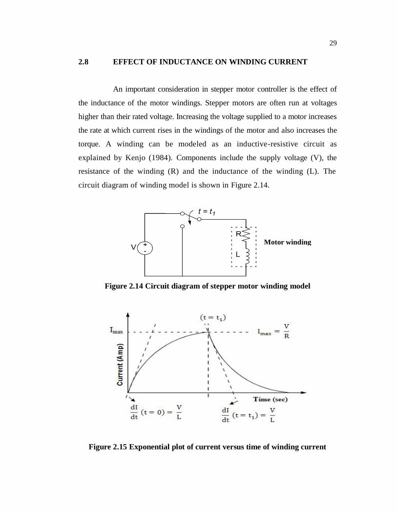
2.8 EFFECT OF INDUCTANCE ON WINDING CURRENT
An important consideration in stepper motor controller is the effect of
the inductance of the motor windings. Stepper motors are often run at voltages
higher than their rated voltage. Increasing the voltage supplied to a motor increases
the rate at which current rises in the windings of the motor and also increases the
torque. A winding can be modeled as an inductive-resistive circuit as
explained by Kenjo (1984). Components include the supply voltage (V), the
resistance of the winding (R) and the inductance of the winding (L). The
circuit diagram of winding model is shown in Figure 2.14.
Figure 2.14 Circuit diagram of stepper motor winding model
Figure 2.15 Exponential plot of current versus time of winding current
Motor winding

30
Inductance of the motor winding determines the rise and fall time of
the current through the windings. The inductance results in an exponential plot of
current versus time as shown in Figure 2.15.
The current rise exponentially until Imax is reached. Current as a
function of time is calculated by
(2.3)
The instantaneous rate at which current rises, when voltage is
applied is given by
(2.4)
The maximum current is given by
(2.5)
The current in the winding will remain at Imax until the supply is
switched OFF. When the voltage supply is removed, the current drops
exponentially. Equations (2.3) and (2.4), show the rate at which current rises in a
winding and can be increased by using a higher supply voltage. Equation (2.5)
shows that Imax is also affected by increasing the supply voltage. Running a motor
at high voltage without current limitations can be damaging for the motor life
and drive circuitry.
31
2.9 CONCLUSION
Basic principles of stepper motor, and there different types and
comparison of stepper motor are presented. The advantages and disadvantages of
hybrid type motor have been explained. Various modes of excitation namely full
step, half step and micro step have been discussed. Also static and dynamic
characteristics of SM are studied.
Related Documents