Flikkema, Paul G. et al. "Microwave and RF Product Applications" The RF and Microwave Handbook Editor in Chief Mike Golio Boca Raton: CRC Press LLC,2001

Welcome message from author
This document is posted to help you gain knowledge. Please leave a comment to let me know what you think about it! Share it to your friends and learn new things together.
Transcript

Flikkema, Paul G. et al. "Microwave and RF Product Applications"The RF and Microwave HandbookEditor in Chief Mike GolioBoca Raton: CRC Press LLC,2001

2Microwave and RF
Product Applications
2.1 Cellular Mobile TelephonyA Brief History • The Cellular Concept • Networks for Mobile Telephony • Standards and Standardization Efforts • Channel Access • Modulation • Diversity Spread Spectrum, and CDMA • Channel Coding, Interleaving, and Time Diversity • Nonlinear Channels • Antenna Arrays • Summary
2.2 Nomadic CommunicationsPrologue • A Glimpse of History • Present and Future Trends • Repertoire of Systems and Services • Airwaves Management • Operating Environment • Service Quality • Network Issues and Cell Size • Coding and Modulation • Speech Coding • Macro and Micro Diversity • Multiple Broadcasting and Multiple Access • System Capacity • Conclusion
2.3 Broadband Wireless Access: High Rate, Point to Multipoint, Fixed Antenna SystemsFundamental BWA Properties • BWA Fills Technology Gaps • BWA Frequency Bands and Market Factors • Standards Activities • Technical Issues: Interfaces and Protocols • Conclusion
2.4 Digital European Cordless TelephoneApplication Areas • DECT/ISDN Interworking • DECT/GSM Interworking • DECT Data Access • How DECT Functions • Architectural Overview
2.5 Wireless Local Area Networks (WLAN)WLAN RF ISM Bands • WLAN Standardization at 2.4 GHz: IEEE 802.11b • Frequency Hopped (FH) vs. Direct Sequence Spread Spectrum (DSSS) • Direct Sequence Spread Spectrum (DSSS) Energy Spreading • Modulation Techniques and Data Rates • Carrier Sense Multiple Access/Collision Avoidance (CSMA/CA) • Packet Data Frames in DSSS • IEEE 802.11 Network Modes • 5 GHz WLAN • RF Link Considerations • WLAN System Example: PRISM® II
2.6 Wireless Personal Area Network Communications: An Application Overview Applications for WPAN Communications • The Nature of WPAN Services • WPAN Architecture • WPAN Protocol Stack • History of WPANs and P802.15 • Conclusions
2.7 Satellite Communications Systems Evolution of Communications Satellites • INTELSAT System Example • Broadband and Multimedia Satellite Systems • Summary
Paul G. FlikkemaNorthern Arizona University
Andy D. Kucar4U Communications Research, Inc.
Brian Petry3Com Corporation
Saf AsgharAdvanced Micro Devices, Inc.
Jim PaviolIntersil
Carl AndrenIntersil
John FakatselisIntersil
Thomas M. SiepTexas Instruments
Ian C. GiffordM/A-Com, Inc.
Ramesh K. GuptaCOMSAT Laboratories
Nils V. JespersenLockheed Martin Space Electronics and Communications
Benjamin B. PetersonU.S. Coast Guard Academy
James L. Bartlett Rockwell Collins
James C. WiltseGeorgia Tech
Melvin L. Belcher, Jr.Georgia Tech
©2001 CRC Press LLC

2.8 Satellite-Based Cellular Communications Driving Factors • Approaches • E xample Architectures •
Trends
2.9 Electronic Navigation SystemsThe Global Positioning System (NAVSTAR GPS) • Global Navigation Satellite System (GLONASS) • LORAN C History and Future • Position Solutions from Radionavigation Data • Error Analysis • Error Ellipses (Pierce, 1948) • Over-Determined Solutions • Weighted Least Squares • Kalman Filters
2.10 AvionicsNavigation, Communications, Voice and Data
2.11 RadarContinuous Wave Radar • Pulse Radar
2.12 Electronic Warfare and CountermeasuresRadar and Radar Jamming Signal Equations • Radar Antenna Vulnerable Elements • Radar Counter-Countermeasures • Chaff
2.13 Automotive RadarClassification • History of Automotive Radar Development • Speed-Measuring Radar • Obstacle-Detection Radar • Adaptive Cruise Control Radar • Collision Anticipation Radar • RD Front-End for Forward-Looking Radars • Other Possible Types of Automotive Radars • Future Developments
2.14 New Frontiers for RF/Microwaves in Therapeutic MedicineRF/Microwave Interaction with Biological Tissues • RF/Microwaves in Therapeutic Medicine • Conclusions
2.1 Cellular Mobile Telephony
Paul G. Flikkema
The goal of modern cellular mobile telephone systems is to provide services to telephone users asefficiently as possible. In the past, this definition would have been restricted to mobile users. However,the cost of wireless infrastructure is less than wired infrastructure in new telephone service markets.Thus, wireless mobile telephony technology is being adapted to provide in-home telephone service, theso-called wireless local loop (WLL). Indeed, it appears that wireless telephony will become dominantover traditional wired access worldwide.
The objective of this section is to familiarize the RF/microwave engineer with the concepts and termi-nology of cellular mobile telephony (“cellular”), or mobile wireless networks. A capsule history and asummary form the two bookends of the section. In between, we start with the cellular concept and thebasics of mobile wireless networks. Then we take a look at some of the standardization issues for cellularsystems. Following that, we cover the focus of the standards battles: channel access methods. We then takea look at some of the basic aspects of cellular important to RF/microwave engineers: first, modulation,diversity, and spread spectrum; then coding, interleaving, and time diversity; and finally nonlinear channels.Before wrapping up, we take a glimpse at a topic of growing importance: antenna array technology.
A Brief History
Mobile telephone service was inaugurated in the U.S. in 1947 with six radio channels available per city.This evolved into the manual Mobile Telephone System (MTS) used in the 1950s and 1960s. The year1964 brought the Improved MTS (IMTS) systems with eight channels per city with — finally — notelephone operator required. Later, the capacity was more than doubled to 18. Most importantly, theIMTS introduced narrowband frequency modulation (NBFM) technology. The first cellular service was
Josh T. NessmithGeorgia Tech
Robert D. HayesRDH Incorporated
Madhu S. GuptaSan Diego State University
Arye RosenDrexel University
Harel D. RosenUMDNJ/Robert Wood Johnson Medical School
Stuart D. EdwardsConway Stuart Medical, Inc.
©2001 CRC Press LLC
introduced in 1983, called AMPS (Advanced Mobile Phone Service). Cities were covered by cells averagingabout 1 km in radius, each serviced by a base station. This system used the 900 MHz frequency bandstill in use for mobile telephony. The cellular architecture allowed frequency reuse, dramatically increasingcapacity to a maximum of 832 channels per cell.
The age of digital, or second-generation, cellular did not arrive until 1995 with the introduction ofthe IS-54 TDMA service and the competing IS-95 CDMA service. In 1996–1997, the U.S. FederalCommunications Commission auctioned licenses for mobile telephony in most U.S. markets in the so-called PCS (Personal Communication System) bands at 1.9 GHz. These systems use a variety of standards,including TDMA, CDMA, and the GSM TDMA standard that originated in Europe. Outside the U.S., asimilar evolution has occurred, with GSM deployed in Europe and the PDC (Personal Digital Cellular)system in Japan. In other countries there has been a pitched competition between all systems. While notsucceeding in the U.S., so-called low-tier systems have been popular in Europe and Japan. These systemsare less robust to channel variations and are therefore targeted to pedestrian use. The European systemis called DECT (Digital European Cordless Telephony) and the Japanese system is called PHS (PersonalHandyphone System).
Third-generation (or 3G) mobile telephone service will be rolled out in the 2001–2002 time frame.These services will be offered in the context of a long-lived standardization effort recently renamed IMT-2000 (International Mobile Telecommunications–2000) under the auspices of the Radio CommunicationsStandardization Sector of the International Telecommunications Union (ITU-R; see http://www.itu.int).Key goals of IMT-2000 are:13
1. Use of a common frequency band over the globe.2. Worldwide roaming capability.3. Transmission rates higher than second-generation systems to handle new data-over-cellular appli-
cations.
Another goal is to provide the capability to offer asymmetric rates, so that the subscriber can downloaddata much faster than he can send it.
Finally, it is hoped that an architecture can be deployed that will allow hardware, software, and networkcommonality among services for a range of environments, such as those for vehicular, pedestrian, andfixed (nonmoving) subscribers. While also aiming for worldwide access and roaming, the main technicalthrust of 3G systems will be to provide high-speed wireless data services, including 144 Kbps service tosubscribers in moving vehicles, 384 Kbps to pedestrian users, 2 Mbps to indoor users, and service viasatellites (where the other services do not reach) at up to 32 Kbps for mobile, hand-held terminals.
The Cellular Concept
At first glance, a logical method to provide radio-based communication service to a metropolitan areais a single, centrally located antenna. However, radio-frequency spectrum is a limited commodity, andregulatory agencies, in order to meet the needs of a vast number of applications, have further limitedthe amount of RF spectrum for mobile telephony. The limited amount of allocated spectrum forceddesigners to adopt the cellular approach: using multiple antennas (base stations) to cover a geographicarea, each base station covers a roughly circular area called a cell. Figure 2.1 shows how a large regioncan be split into seven smaller cells (approximated by hexagons). This allows different base stations touse the same frequencies for communication links as long as they are separated by a sufficient distance.This is known as frequency reuse, and allows thousands of mobile telephone users in a metropolitan areato share far fewer channels.
There is a second important aspect to the cellular concept. With each base station covering a smallerarea, the mobile phones need less transmit power to reach any base station (and thus be connected withthe telephone network). This is a major advantage, since, with battery size and weight a major impedimentto miniaturization, the importance of reducing power consumption of mobile phones is difficult tooverestimate.
©2001 CRC Press LLC

If two mobile units are connected to their respective base stations at the same frequency (or moregenerally, channel), interference between them, called co-channel interference, can result. Thus, there isa trade-off between frequency reuse and signal quality, and a great deal of effort has resulted in frequencyassignment techniques that balance this trade-off. They are based on the idea of clustering: taking theavailable set of channels, allocating them in chunks to each cell, and arranging the cells into geographicallylocal clusters. Figure 2.2 shows how clusters of seven cells (each allocated one of seven mutually exclusive
FIGURE 2.1 A region divided into cells. While normally the base stations are placed at the center of the cells, it isalso possible to use edge-excited cells where base stations are placed at vertices.
FIGURE 2.2 Cell planning with cluster size of 7. The number in each cell indexes the subset of channels allocatedto the cell. Other cluster sizes, such as 4, 7, or 12 can be used.
27
13
45
62
71
3
45
6
27
13
45
62
71
3
45
6
©2001 CRC Press LLC

channel subsets) are used to cover a large region; note that the arrangement of clusters maximizes thereuse distance — the distance between any two cells using the same frequency subset. Increasing thereuse distance has the effect of reducing co-channel interference.
Although it might seem attractive to make the cells smaller and smaller, there are diminishing returns.First, smaller cell sizes increase the need for management of mobile users as they move about. In otherwords, smaller cell sizes require more handoffs, where the network must transfer users between basestations. Another constraint is antenna location, which is often limited by available space and esthetics.Fortunately, both problems can be overcome by technology. Greater handoff rates can be handled byincreases in processing speed, and creative antenna placement techniques (such as on lamp posts or sidesof buildings) are allowing higher base station densities.
Another issue is evolution: how can a cellular system grow with demand? Two methods have beensuccessful. The first is cell splitting: by dividing a cell into several cells (and adjusting the reuse pattern),a cellular service provider can increase its capacity in high-demand areas. The second is sectoring: insteadof a single omnidirectional antenna covering a cell, a typical approach is to sectorize the cell into NS
regions, each served by an antenna that covers an angular span of 2π/NS (NS = 3 is typical). Note thatboth approaches increase handoff rates and thus require concurrent upgrading of network management.Later we will describe smart antennas, the logical extension to sectorization.
Networks for Mobile Telephony
A communication network that carries only voice — even a digital one — is relatively simple. Otherthan the usual digital communication system functions, such as channel coding, modulation, and syn-chronization, all that is required is call setup and takedown. However, current and future digital mobiletelephony networks are expected to carry digital data traffic as well.
Data traffic is by nature computer-to-computer, and requires that the network have an infrastructurethat supports everything from the application (such as Web browsing) to the actual transfer of bits. Thedata is normally organized into chunks called packets (instead of streams as in voice), and requires a muchhigher level of reliability than digitized voice signals. These two properties imply that the network mustalso label the packets, and manage the detection and retransmission of packets that are received in error.It is important to note that packet retransmission, while required for data to guarantee fidelity, is notpossible for voice because it would introduce delays that would be intolerable in a human conversation.
Other functions that a modern digital network must perform include encryption and decryption (fordata security) and source coding and decoding. The latter functions minimize the amount of the channelresource (in essence, bandwidth) needed for transferring the information. For voice networks this involvesthe design of voice codecs (coder/decoders) that not only digitize voice signals, but strip out the redundantinformation in them. In addition to all the functions that wired networks provide, wireless networkswith mobile users must also provide mobility management functions that keep track of calls as subscribersmove from cell to cell.
The various network functions are organized into layers to rationalize the network design and to easeinternetworking, or the transfer of data between networks.11 RF/microwave engineering is part of thephysical layer that is responsible for carrying the data over the wireless medium.
Standards and Standardization Efforts
The cellular industry is, if anything, dense with lingo and acronyms. Here we try to make sense of atleast some of the important and hopefully longer-lived terminology.
Worldwide, most of the cellular services are offered in two frequency bands: 900 and 1900 MHz. Ineach of the two bands, the exact spectrum allocated to terrestrial mobile services varies from country tocountry. In the U.S. cellular services are in the 800 to 900 MHz band, while similar services are in the800 to 980 MHz band in Europe under the name GSM900. (GSM900 combines in one name a radiocommunication standard — GSM, or Global System for Mobile Communications — and the frequency
©2001 CRC Press LLC

band in which it is used. We will describe the radio communication, or air interface, standards later). Inthe mid-1990s, the U.S. allocated spectrum for PCS (Personal Communication Services) from 1850 to2000 MHz; while many thought PCS would be different from cellular, they have converged and areinterchangeable from the customer’s perspective. Similarly, in Europe GSM1800 describes cellular servicesoffered using the 1700 to 1880 MHz band.
The 1992 World Administrative Radio Conference (WARC ’92) allocated spectrum for third-generationmobile radio in the 1885 to 1980 and 2110 to 2160 MHz bands. The ITU-Rs IMT-2000 standardizationinitiative adopted these bands for terrestrial mobile services. Note that the IMT-2000 effort is an umbrellathat includes both terrestrial and satellite-based services — the latter for areas where terrestrial servicesare unavailable.
Please note that all figures here are approximate and subject to change in future WARCs; please consultReferences 2 and 13 for details.
The cellular air interface standards are designed to allow different manufacturers to develop both basestation and subscriber (mobile user handset) equipment. The air interface standards are generally differentfor the downlink (base station to handset) and uplink (handset to base station). This reflects the asym-metry of resources available: the handsets are clearly constrained in terms of power consumption andantenna size, so that the downlink standards imply sophisticated transmitter design, while the uplinkstandards emphasize transmitter simplicity and advanced receive-side algorithms. The air interface stan-dards address channel access protocols as well as traditional communication link design parameters suchas modulation and coding. These issues are taken up in the following sections.
Channel Access
In a cellular system, a fixed amount of RF spectrum must somehow be shared among thousands ofsimultaneous phone conversations or data links. Channel access is about (1) dividing the allocated RFspectrum into pieces and (2) allocating the pieces to conversations/links in an efficient way.
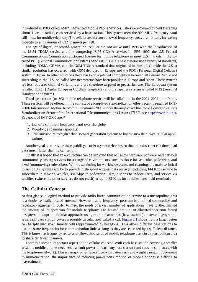
The easiest channel access method to envision is FDMA (Frequency Division Multiple Access), whereeach link is allocated a sub-band (i.e., a specific carrier frequency; see Fig. 2.3). This is exactly the accessmethod used by first generation (analog) cellular systems. The second generation of cellular brought twonewer channel access methods that were enabled by progress in digital process technology. One is TDMA(Time Division Multiple Access), wherein time is divided into frames, and links are given short time slotsin each frame (Fig. 2.4). FDMA and TDMA can be seen as time/frequency duals, in that FDMA subdividesthe band into narrow sub-bands in the frequency domain, while TDMA subdivides time into slots, duringwhich a link (within a cell) uses the entire allocated bandwidth.
FIGURE 2.3 FDMA depicted on the time-frequency plane, with users assigned carrier frequencies, or channels.Not shown are guard bands between the channels to prevent interference between users’ signals.
Time
User k
©2001 CRC Press LLC
The second generation of cellular also brought CDMA (Code Division Multiple Access). In CDMA,all active links simultaneously use the entire allocated spectrum, but sophisticated codes are used thatallow the signals to be separated in the receiver.1 We will describe CDMA in more depth later.
It should be noted that both TDMA- and CDMA-based cellular systems also implicitly employ FDMA,although this is rarely mentioned. The reason is that the cellular bands are divided into smaller bands(a form of FDMA), and both TDMA and CDMA are used within these sub-bands.
In the U.S., the TDMA and CDMA standards are referred to by different acronyms. The TDMAstandard originally was called IS-54, but with enhancements became IS-136. The CDMA standard wascalled IS-95, and has been re-christened as cdmaOne by its originator, Qualcomm. These standards werecreated under the auspices of the Telecommunications Industry Association (TIA) and the ElectronicIndustries Alliance (EIA).
In Europe, the second generation brought digital technology in the form of the GSM standard, whichused TDMA. (The GSM acronym originally referred to Group Special Mobile, but was updated to captureits move to worldwide markets.) Japan also chose TDMA in its first digital offering, called PDC (PersonalDigital Cellular).
The three multiple access approaches use different signal properties (frequency, time, or code) to allowthe distinguishing of multiple signals. How do they compare? In the main, as we move from FDMA toTDMA to CDMA (in order of their technological development), complexity is transferred from the RFsection to the digital section of the transmitters and receivers. The evolution of multiple access techniqueshas tracked the rapid evolution of digital processing technology as the latter has become cheaper andfaster. For example, while FDMA requires a tunable RF section, both TDMA and CDMA need only afixed-frequency front end. CDMA relieves one requirement of TDMA — strict synchronization amongthe various transmitters — but introduces a stronger requirement for synchronization of the receiver tothe received signal. In addition, the properties of the CDMA signal provide a natural means to exploitthe multipath nature of the digital signal for improved performance. However, these advantages comeat the cost of massive increases in the capability of digital hardware. Luckily, Moore’s Law (i.e., thatprocessing power roughly doubles every 18 months at similar cost) still remains in effect as of the turnof the century, and the amount of processing power that will be used in the digital phones in the 21stcentury will be unimaginable to the architects of the analog systems developed in the 1970s.
FIGURE 2.4 Depiction of TDMA on the time-frequency plane. Users are assigned time slots within a frame. Guardtimes (not shown) are needed between slots to compensate for timing inaccuracies.
1It is fashionable to depict CDMA graphically using a “code dimension” that is orthogonal to the time-frequencyplane, but this is an unfortunate misrepresentation. Like any signals, CDMA signals exist (in fact, overlap) in thetime-frequency plane, but have correlation-based properties that allow them to be distinguished.
Time
User k User k
©2001 CRC Press LLC

Modulation
The general purpose of modulation is to transform an information-bearing message signal into a relatedsignal that is suitable for efficient transmission over a communication channel. In analog modulation,this is a relatively simple process: the information-bearing analog (or continuous-time) signal is used toalter a parameter (normally, the amplitude, frequency, or phase) of a sinusoidal signal (or carrier, thesignal carrying the information). For example, in the NBFM modulation used in the AMPS system, thevoice signal alters the frequency content of the modulated signal in a straightforward manner.
The purpose of digital modulation is to convert an information-bearing discrete-time symbol sequenceinto a continuous-time waveform. Digital modulation is easier to analyze than analog modulation, butmore difficult to describe and implement.
Modulation in Digital Communication
Before digital modulation of the data in the transmitter, there are several processing steps that must beapplied to the original message signal to obtain the discrete-time symbol sequence. A continuous-timemessage signal, such as the voice signal in telephony, is converted to digital form by sampling, quanti-zation, and source coding. Sampling converts the original continuous-time waveform into discrete-timeformat, and quantization approximates each sample of the discrete-time signal using one of a finitenumber of levels. Then source coding jointly performs two functions: it strips redundancy out of thesignal and converts it to a discrete-time sequence of symbols.
What if the original signal is already in discrete-time (sampled format), such as a computer file? Inthis case, no sampling or quantization is needed, but source coding is still used to remove redundancy.
Between source coding and modulation is a step critical to the efficiency of digital communications:channel coding. This is discussed later; it suffices for now to know that it converts the discrete-timesequence of symbols from the source coder into another (better) discrete-time symbol sequence for inputto the modulator. Following modulation, the signal is upconverted, filtered (if required), and amplifiedin RF electronics before being sent to the antenna. All the steps described are shown in block-diagramform in Fig. 2.5. In the receiver, the signal from the antenna, following filtering (again, if required), isamplified and downconverted prior to demodulation, channel decoding, and source decoding (seeFig. 2.5).
What is the nature of the digital modulation process? The discrete-time symbol sequence from thechannel coder is really a string of symbols (letters) from a finite alphabet. For example, in binary digitalmodulation, the input symbols are 0’s and 1’s. The modulator output converts those symbols into oneof a finite set of waveforms that can be optimized for the channel.
While it is the finite set of waveforms that distinguishes digital modulation from analog modulation,that difference is only one manifestation of the entire paradigm of digital communication. In a good digitalcommunication design, the source coder, channel coder, and modulator all work together to maximizethe efficient use of the communication channel; even two of the three are not enough for good performance.
FIGURE 2.5 Communication system block diagram for wireless communication. In the wireless medium, multipathpropagation and interference can be introduced. For system modeling purposes, the two blocks of RF electronics arecombined with the wireless medium to form the wireless channel — a channel that distorts the signal, and addsnoise and interference. The other blocks are designed to maximize the system performance for the channel.
InfoSource
Desti-nation
RF Elec-tronics
RF Elec-tronics
SourceCoder
SourceDecoder
ChannelCoder
ChannelDecoder
Modu-lator
Demod-ulator
Wireless Medium
Transmitter
Receiver
©2001 CRC Press LLC

Selection of Digital Modulation Formats
There are several (often conflicting) criteria for selection of a modulation scheme. They are:
• BER (bit error rate) performance
• in wireless, particularly in cellular mobile channels, the scheme must operate under conditionsof severe fading
• cellular architectures imply co-channel interference• Typically, a BER of 10–2 or better is required for voice telephony, and 10–5 or better is required
for data.
• Spectral (or bandwidth) efficiency (measured in bits/s/Hz)
• Power efficiency (especially for hand-held/mobile terminals)
• Implementation complexity and cost
In the U.S. cellular market, complexity is of special importance: with the number of standards growing,many handsets are now dual- and triple-mode; for example, a phone might have both GSM and 3Gcapability. While some hardware can be shared, multimode handsets clearly place additional constraintson the allowable complexity for each mode.
Classification of Digital Modulation Schemes
Broadly, modulation techniques can be classified into two categories.Linear methods include schemes that use combinations of amplitude and phase modulation of a pulse
stream. They have higher spectral efficiencies than constant-envelope methods (see the following), butmust use more-expensive (or less efficient) linear amplifiers to maintain performance and to limit out-of-band emissions.
Examples of linear modulation schemes include PSK (phase-shift keying) and QAM (quadratureamplitude modulation). QAM can be viewed as a generalization of PSK in that both the amplitude andthe phase of the modulated waveform are altered in response to the input symbols.
Constant-envelope methods are more complicated to describe, but usually are sophisticated methodsbased on frequency modulation. Their key characteristic is a constant envelope (resulting in a constantinstantaneous signal power) regardless of the source symbol stream. They allow use of less expensive ampli-fication and/or higher amplification efficiencies (e.g., running amplifiers in the nonlinear region), at theexpense of out-of-band emissions. Historically, they are limited to spectral efficiencies of about 1 bit/s/Hz.
Examples of constant envelope methods include FSK (frequency-shift keying) and more sophisticatedmethods such as MSK and GMSK (these will be described shortly). These methods can be thought of as digital(finite alphabet) FM in that the spectrum of the output signal is varied according to the input symbol stream.
The spectral occupancy of a modulated signal (per channel) is roughly
where B is the bandwidth occupied by signal power spectrum and ∆f is the maximum one-way carrierfrequency drift.2 We can express the bandwidth
where Rd is the channel data rate (in bits/s) and � is the spectral efficiency (in bits/s/Hz). Combining, we obtain
2This drift can be caused by oscillator instability or Doppler due to channel time variations.
S B fO = +2∆ ,
BRd=�
,
SR
fOd= +
�2∆ .
©2001 CRC Press LLC

Thus, to minimize spectral occupancy (thus maximizing capacity in number of users) we can:
1. Reduce Rd by lowering the source coding rate (implying more complexity or lower fidelity), or2. Improve the spectral efficiency of the modulation (implying higher complexity), or3. Improve the transmitter/receiver oscillators (at greater cost).
Modulation, Up/Downconversion, and Demodulation
To transmit a string of binary information symbols (or bits — zeros and ones), {b0, b1, b2, …}, we canrepresent a 1 by a positive-valued pulse of amplitude one, and a 0 by a negative pulse of the sampleamplitude. This mapping from the bit value at time n, bn, to amplitude an can be accomplished using
To complete the definition, we define a pulse of unit amplitude with start time of zero and stop time ofT as pT(t). Then the modulated signal can be efficiently written as
This signal is at baseband — centered at zero frequency — and is therefore unsuitable for wirelesscommunication media. However, this signal can be upconverted to a desired RF by mixing with a sinusoidto get the passband signal
where fc is the carrier frequency.Multiplying a sinusoid by ±1 is identical to changing its phase between 0 and π radians, so we have
where we assign dn = 0 when an = –1 and dn = π when an = 1. This equation shows that we are simplyshifting the phase of the carrier between two different values: this is BPSK (binary phase-shift keying).
Why not use more than two phase values? In fact, four are ordinarily used for better efficiency: pairsof bits are mapped to four different phase values, 0, ±π/2, and π. For example, the CDMA standardsemploy this scheme, known as quaternary PSK (QPSK).
In general, the baseband signal will be complex-valued, which leads to the general form of upconversionfrom baseband to passband:
where the factor is simply to maintain a consistency in measurement of signal power between passbandand baseband. The motivation of using the baseband representation of a signal is twofold: first, it retainsthe amplitude and phase of the passband signal, and is thus independent of any particular carrier frequency;second, it provides the basis for modern baseband receiver implementations that use high-speed digitalsignal processing. The baseband representation is also known as the complex envelope representation.
BPSK and QPSK are linear modulation methods; in contrast, FSK is a constant-envelope modulationscheme. For binary FSK (BFSK), there are two possible signal pulses, given at baseband by
a bn n= −2 1.
u t a p t nTn T
n
( ) = −( )∑ .
x t u t f t f t a p t nTc c n T
n
( ) = ( ) π( ) = π( ) −( )∑cos cos ,2 2
x t f t d p t nTc n T
n
( ) = π + −( )
∑cos ,2
x t u t e j f tc( ) = ℜ ( ){ }π2 2 ,
2
©2001 CRC Press LLC

where A is the amplitude. Notice that we have two (complex) tones separated by ∆f. MSK (minimum-shift keying) and GMSK (Gaussian prefiltered MSK) are special forms of FSK that provide greater spectralefficiency at the cost of higher implementation efficiency. The GSM standard and its next-generationversion, currently known as EDGE (for Enhanced Data Rates for Global Evolution), use GMSK.
At the receiver, the RF signal is amplified and downconverted with appropriate filtering to removeinterference and noise. The downconverted signal is then passed to the demodulator, whose function isto detect (guess in an optimum way) what symbol stream was transmitted. Following demodulation (alsoreferred to as detection), the symbol stream is sent to subsequent processing steps (channel decodingand source decoding) before delivery to the destination.
At this point it is typical to consider the BERs and spectral efficiencies of various digital modulationformats, modulator and demodulator designs, and the performance of different detection strategies formobile cellular channels. This is beyond the scope of this section, and we direct the reader to a goodbook on digital communications (e.g., References 1, 4, 6, 7, 8) for more information.
Diversity, Spread Spectrum, and CDMA
A mobile wireless channel causes the transmitted signal to arrive at the receiver via a number of pathsdue to reflections from objects in the environment. If the channel is linear (including transmit and receiveamplifiers), a simple modeling approach for this multipath channel is to assume that it is specular, i.e.,each path results in a specific amplitude, time delay, and phase change. If the channel is also at leastapproximately time-invariant, its impulse response under these conditions can be expressed as3
where αλ, τλ, and θλ are, respectively, the amplitude, time delay, and phase for the λ-th path.Let the transmitted signal be
a sequence of pulses fn(t) each modulated by a transmitted symbol an at a symbol rate of 1/T. Whentransmitted via a specular multipath channel with Λ paths, the received signal — found by the convolutionof the transmitted signal and the channel impulse response — is
.
For simplicity, consider sending only three symbols a–1, a0, a1. Then the received signal becomes
3Here δ(t) denotes the Dirac delta function.
u t Ae p t u t Ae p tj ftT
j ftT0 1( ) = ( ) ( ) = ( )− π π∆ ∆, ,
h t e tj( ) = −( )=
∑α δ τλθ
λλ
λ
0
Λ
,
s t a f tn n
n
( ) = ( )∑ ,
y t e s tj( ) = −( )=
∑α τλθ
λλ
λ
0
Λ
y t a e f tn
n
jn( ) = −( )
=− =∑ ∑
1
1
0
α τλθ
λλ
λ
Λ
.
©2001 CRC Press LLC

Two effects may result: fading and intersymbol interference. Fading occurs when superimposedreplicas of the same symbol pulse nullify each other due to phase differences. Intersymbol interference(ISI) is caused by the convolutive mixing of the adjacent symbols in the channels. Fading and ISI mayoccur individually or together depending on the channel parameters and the symbol rate T –1 of thetransmitted signal.
Let us consider in more detail the case where the channel delay spread is a significant fraction of T,i.e., τΛ is close to, but smaller than T. In this case, we can have both fading and ISI, which, if left untreated,can severely compromise the reliability of the communication link. Direct-sequence spread-spectrum(DS/SS) signaling is a technique that mitigates these problems by using clever designs for the pulses fn(t).These pulse designs are wide bandwidth (hence “spread spectrum”), and the extra bandwidth is used toendow them with properties that allow the receiver to separate the symbol replicas.
Suppose we have a two-path channel, and consider the received signal for symbol a0. Then the DS/SSreceiver separates the two replicas
Then each replica is adjusted in phase by multiplying it by e – j θλ, λ = 0, 1 yielding (since zz* = �z�2)
Now all that remains is to delay the first replica by τ1 – τ0 so they line up in time, and sum them, which gives
Thus DS/SS can turn the multipath channel to advantage — instead of interfering with each other, thetwo replicas are now added constructively. This multipath combining exploits the received signal’s inherentmultipath diversity, and is the basic idea behind the technology of RAKE reception4 used in the CDMAdigital cellular telephony standards.
It is important to note that this is the key idea behind all strategies for multipath fading channels: wesomehow exploit the redundancy, or diversity of the channel (recall the multiple paths). In this case, weused the properties of DS/SS signaling to effectively split the problematic two-path channel into twobenign one-path channels. Multipath diversity can also be viewed in the frequency domain, and is ineffect a form of frequency diversity. As we will see later, frequency diversity can be used in conjunctionwith other forms of diversity afforded by wireless channels, including time diversity and antenna diversity.
CDMA takes the spread spectrum idea and extends it to the separation of signals from multipletransmitters. To see this, suppose M transmitters are sending signals simultaneously, and assume forsimplicity that we have a single-path channel. Let the complex (magnitude/phase) gain for channel mbe denoted by β(m). Finally, the transmitters use different spread-spectrum pulses, denoted by f (m)(t). Ifwe just consider the zeroth transmitted symbols from each transmitter, we have the received signal
where the time offset tm indicates that the pulses do not necessarily arrive at the same time.
4The RAKE nomenclature can be traced to the block diagram representation of such a receiver — it is reminiscentof a garden rake.
α τ α τθ θ0 0 0 1 0 0 1
0 1e a f t e a f tjp
j−( ) −( ), .
α τ α τ0 0 0 1 0 1a f t a f t−( ) −( ), .
α α τ0 1 0 1+( ) −( )a f t .
y t a f t tm m m
m
m
M
( ) = −( )( ) ( ) ( )=
∑β 0
1
©2001 CRC Press LLC

The above equation represents a complicated mixture of the signals from multiple transmitters. Ifnarrowband pulses are used, they would be extremely difficult — probably impossible — to separate.However, if the pulses are spread-spectrum, then the receiver can use algorithms to separate them fromeach other, and successfully demodulate the transmitted symbols. Of course, these ideas can be extendedto many transmitters sending long strings of symbols over multipath channels.
Why is it called CDMA? It turns out that the special properties of the signal pulses f (m)(t) for eachuser (transmitter) m derive from high-speed codes consisting of periodic sequences of chips c(m)
k thatmodulate chip waveforms ϕ(t). One way to envision it is to think of ϕ(t) as a rectangular pulse of durationTc = T/N. The pulse waveform for user m can then be written
The fact that we can separate the signals means that we are performing code-division multiple access —dividing up the channel resource by using codes. Recall that in FDMA this is done by allocating frequencybands, and in TDMA, time slots. The pulse waveforms in CDMA are designed so that many users’ signalsoccupy the entire bandwidth simultaneously, yet can still be separated in the receiver. The signal-separating capability of CDMA is extremely important, and can extend beyond separating desired signalswithin a cell. For example, the IS-95 CDMA standard uses spread-spectrum pulse designs that enablethe receiver to reject a substantial amount of co-channel interference (interference due to signals in othercells). This gives the IS-95 system (as well as its proposed 3G descendants) its well-known property ofuniversal frequency reuse.
The advantages of DS/SS signals derive from what are called their deterministic correlation properties.For an arbitrary periodic sequence {c(m)
k }, the deterministic autocorrelation is defined as
where i denotes the relative shift between two replicas of the sequence. If {c(m)k } is a direct-sequence
spreading code, then
This “thumbtack” autocorrelation implies that relative shifts of the sequence can be separated from eachother. Noting that each chip is a fraction of a symbol duration, we see that multipath replicas of a symbolpulse can be separated even if their arrival times at the receiver differ by less than a symbol duration.
CDMA signal sets also exhibit special deterministic cross-correlation properties. Two spreading codes{c(l)
k }, {c(m)k } of a CDMA signal set have the cross-correlation property
Thus, we have a set of sequences with zero cross-correlations and “thumbtack” autocorrelations. (Notethat this includes the earlier autocorrelation as a special case.) The basic idea of demodulation for CDMA
f t c t kTm
k
m
c
k
N
( ) ( )=
−
( ) = −( )∑ ϕ0
1
.
φ m
k
m
k i
m
k
N
iN
c c( ) ( )+
( )=
−
( ) = ∑1
0
1
,
φ mi
i
i N( )( ) ≈
=< <
1 0
0 1
,
, .
φ l m
k
l
k i
m
k
N
iN
c c
l m i
l m i N
l m
,
, , ,
, , ,
, .
( ) ( )+
( )=
−
( ) = ≈= == < <
≠
∑11 0
0 0
00
1
©2001 CRC Press LLC

is as follows: if the signal from user m is desired, the incoming received signal — a mixture of multipletransmitted signals — is correlated against {c(m)
k }. Thus multiple replicas of a symbol from user m canbe separated, delayed, and then combined, while all other users’ signals (i.e., where l ≠ m) are suppressedby the correlation.
Details of these properties, their consequences in demodulation, and descriptions of specific codedesigns can be found in References 3, 4, 7, and 10.
Channel Coding, Interleaving, and Time Diversity
As we have mentioned, channel coding is a transmitter function that is performed after source coding,but before modulation. The basic idea of channel coding is to introduce highly structured redundancyinto the signal that will allow the receiver to easily detect or correct errors introduced in the transmissionof the signal.
Channel coding is fundamental to the success of modern wireless communication. It can be consideredthe cornerstone of digital communication, since, without coding, it would not be possible to approachthe fundamental limits established by Shannon’s information theory.9,12
The easiest type of channel codes to understand are block codes: a sequence of input symbols of length kis transformed into a code sequence (codeword) of length n > k. Codes are often identified by theirrate R, where R = k/n ≤ 1. Generally, codes with a lower rate are more powerful. Almost all block codesare linear, meaning that the sum of two codewords is another codeword. By enforcing this linear structure,coding theorists have found it easier to find codes that not only have good performance, but havereasonably simple decoding algorithms as well.
In wireless systems, convolutional codes are very popular. Instead of blocking the input stream intolength-k sequences and encoding each one independently, convolutional coders are finite-state sequentialmachines. Therefore they have memory, so that a particular output symbol is determined by a contiguoussequence of input symbols. For example, a rate-1/2 convolutional coder outputs two code symbols foreach information symbol that arrives at its input. Normally, these codes are also linear.
Error-correcting codes have enough power so that errors can actually be corrected in the receiver. Systemsthat use these codes are called forward error-control (FEC) systems. Error-detecting codes are simpler, butless effective: they can tell whether an error has occurred, but not where the error is located in the receivedsequence, so it cannot be corrected.
Error-detecting codes can be useful when it is possible for the receiver to request retransmission of acorrupted codeword. Systems that employ this type of feedback are called ARQ, or Automatic Repeat-reQuest systems.
As we have seen, the fading in cellular systems is due to multipath. Of course, as the mobile unit andother objects in the environment move, the physical structure of the channel changes with time, causingthe fading of the channel to vary with time. However, this fading process tends to be slow relative to thesymbol rate, so a long string of coded symbols can be subjected to a deep channel fade. In other words,the fading from one symbol to the next will be highly correlated. Thus, the fades can cause a large stringof demodulation (detection) errors, or an error burst. Thus, fading channels are often described fromthe point of view of coding as burst-error channels.
Most well-known block and convolutional codes are best suited to random errors, that is, errors thatoccur in an uncorrelated fashion and thus tend to occur as isolated single errors. While there have beena number of codes designed to correct burst errors, the theory of random error-correcting codes is sowell developed that designers have often chosen to use these codes in concert with a method to “ran-domize” error bursts.
This randomization method, called interleaving, rearranges, or scrambles, the coded symbols in orderto minimize this correlation so that errors are isolated and distributed across a number of codewords.Thus, a modest random-error correcting code can be combined with interleaving that is inserted betweenthe channel coder and the modulator to shuffle the symbols of the codewords. Then, in the receiver, the
©2001 CRC Press LLC

de-interleaver is placed between the demodulator and the decoder is reassemble the codewords fordecoding.
We note that a well-designed coding/interleaving system does more than redistribute errors for easycorrection: it also exploits time diversity. In our discussion of spread-spectrum and CDMA, we saw howthe DS/SS signal exploits the frequency diversity of the wireless channel via its multipath redundancy.Here, the redundancy added by channel coding/interleaving is designed so that, in addition to the usualperformance increase due to just the code — the coding gain — there is also a benefit to distributing theredundancy in such a way that exploits the time variation of the channel, yielding a time diversity gain.
In this era of digital data over wireless, high link reliability is required. This is in spite of the fact thatmost wireless links have a raw bit error rate (BER) on the order of 1 in 1000. Clearly, we would like tosee an error rate of 1 in 1012 or better. How is this astounding improvement achieved? The followingtwo-level approach has proved successful. The first level employs FEC to correct a large percentage ofthe errors. This code is used in tandem with a powerful error-detecting algorithm to find the rare errorsthat the FEC cannot find and correct. This combined FEC/ARQ approach limits the amount of feedbackto an acceptable level while still achieving the necessary reliability.
Nonlinear Channels
Amplifiers are more power-efficient if they are driven closer to saturation than if they are kept withintheir linear regions. Unfortunately, nonlinearities that occur as saturation is approached lead to spectralspreading of the signal. This can be illustrated by observing that an instantaneous (or memoryless)nonlinearity can be approximated by a polynomial. For example, a quadratic term effectively squares thesignal; for a sinusoidal input this leads to double-frequency terms.
A more sophisticated perspective comes from noting that the nonlinear amplification can distort thesymbol pulse shape, expanding the spectrum of the pulse. Nonlinearities of this type are said to cause AM/AMdistortion. Amplifiers can also exhibit AM/PM conversion, where the output phase of a sinusoid is shiftedby different amounts depending on its input power — a serious problem for PSK-type modulations.
A great deal of effort has gone into finding transmitter designs that allow more efficient amplifieroperation. For example, constant-envelope modulation schemes are insensitive to nonlinearities, andsignaling schemes that reduce the peak-to-average power ratio (PAPR) of the signal allow higher levels.Finally, methods to linearize amplifiers at higher efficiencies are receiving considerable attention.
Modeling and simulating nonlinear effects on system performance is a nontrivial task. AM/AM andAM/PM distortions are functions of frequency, so if wideband amplifier characterization is required, afamily of curves is necessary. Even then the actual wideband response is only approximated, since thesesystems are limited in bandwidth and thus have memory. More accurate results in this case can beobtained using Volterra series expansions, or numerical solutions to nonlinear differential equations.Sophisticated approaches are becoming increasingly important in cellular as supported data rates movehigher and higher. More information can be found in References 1 and 5 and the references therein.
Antenna Arrays
We have seen earlier how sectorized antennas can be used to increase system performance. They are oneof the most economical forms of multielement antenna systems, and can be used to reduce interferenceor to increase user capacity. A second use of multielement systems is to exploit the spatial diversity ofthe wireless channel. Spatial diversity approaches assume that the received antenna elements are immersedin a signal field whose strength varies strongly with position due to a superposition of multipath signalsarriving via various directions. The resulting element signal strengths are assumed to be at least somewhatstatistically uncorrelated. This spatial uncorrelatedness is analogous to the uncorrelatedness over time orfrequency that is exploited in mobile channels.
One of the simplest approaches is to use multiple (normally omnidirectional in azimuth) antennaelements at the receiver, and choose the one with the highest signal-to-noise ratio. More sophisticated
©2001 CRC Press LLC

schemes combine — rather than select just one of — the element signals to further improve the signal-to-noise ratio at the cost of higher receiver complexity. These approaches date from the 1950s, and donot take into account other interfering mobile units. These latter schemes are often grouped under thecategory of antenna diversity approaches.
More recently, a number of proposals for systems that combine error-control coding mechanisms withmultiple elements have been made under the name of space-time coding. One of the main contributionsof these efforts has been the recognition that multiple-element transmit antennas can, under certainconditions, dramatically increase the link capacity.
Another approach, beamforming or phased-array antennas, is also positioned to play a role in futuresystems under the new moniker smart antennas. Space-time coding and smart antenna methods can beseen as two approaches to exploiting the capabilities of multiple-input/multiple-output (MIMO) systems.However, in contrast to space-time coding approaches, strong inter-element correlation based on thedirection of arrival of plane waves is assumed in smart antennas. The basic idea of smart antennas is toemploy an array of antenna elements connected to an amplitude- and phase-shifting network to adaptivelytune (steer electronically) the antenna pattern based on the geographic placement of mobile units. Muchof the groundwork for smart antenna systems was laid in the 1950s in military radar research. The ultimategoal of these approaches can be stated as follows: to track individual mobile units with optimized antennapatterns that maximize performance (by maximizing the ratio of the signal to the sum of interference andnoise) minimize power consumption at the mobile unit, and optimize the capacity of the cellular system.One can conjecture that the ultimate solution to this problem will be a class of techniques that involve jointdesign of channel coding, modulation, and antenna array processing in an optimum fashion.
Summary
Almost all wireless networks are distinguished by the characteristic of a shared channel resource, andthis is in fact the key difference between wireless and wired networks. Another important differencebetween wired and wireless channels is the presence of multipath in the latter, which makes diversitypossible. What is it that distinguishes cellular from other wireless services and systems? First, it historicallyhas been designed for mobile telephone users, and has been optimized for carrying human voice. Thishas led to the following key traits of cellular:
• efficient use of spectrum via the cellular concept;
• system designs, including channel access mechanisms, that efficiently handle large numbers ofuniform — i.e., voice — links; and
• difficult channels: user mobility causes fast variations in channel signal characteristics comparedwith other wireless applications such as wireless local area networks.
We close by mentioning two apparent trends. First, as we mentioned at the outset of this article,wireless local loop services, where home telephone subscribers use wireless phones — and the “last mile”is wireless rather than copper — are a new application for mobile wireless technology. Secondly, at thistime there is a great deal of effort to make next-generation cellular systems useful for data networkingin addition to voice. Certainly, the amount of data traffic on these networks will grow. However, one ofthe largest questions for the next ten years is whether mobile wireless will win the growing data market,or if new data-oriented wireless networks will come to dominate.
References
1. Zeng, M., Annamalai, A., and Bhargava, V. K., Recent advances in cellular wireless communications,IEEE Communications Magazine, 37, 9, 128–138, September 1999.
2. Walrand, J., and Varaiya, P., High-Performance Communication Networks, Morgan Kaufman, SanFrancisco, CA, 1996.
3. Chaudhury, P., Mohr, W., and Onoe, S., The 3GPP proposal for IMT-2000, IEEE CommunicationsMagazine, 37 (12), 72–81, December 1999.
©2001 CRC Press LLC

4. Anderson, J. B., Digital Transmission Engineering, IEEE Press, Piscataway, NJ, 1999.5. Lee, E. A., and Messerschmitt, D. G., Digital Communication, Kluwer Academic, second edition, 1994.6. Proakis, J. G., Digital Communications, 3rd ed., McGraw-Hill, New York, 1995.7. Haykin, S., Communication Systems, Wiley, New York, 1994.8. Proakis, J. G., and Salehi, M., Communication Systems Engineering, Prentice-Hall, Englewood Cliffs,
NJ, 1994.9. Flikkema, P., Introduction to spread spectrum for wireless communication: a signal processing
perspective, IEEE Spectrum Processing Magazine, 14, 3, 26–36, May 1997.10. Viterbi, A. J., CDMA: Principles of Spread Spectrum Communication, Addison-Wesley, 1995.11. Shannon, C. E., Communication in the presence of noise, Proceedings of the IRE, 37, 1,10–21,
January 1949.12. Wyner, A. D., and Shamai (Shitz), S., Introduction to “Communication in the presence of noise”
by C. E. Shannon, Proceedings of the IEEE, 86, 2, 442–446, February 1998. Reprinted in theProceedings of the IEEE, vol. 86, no. 2, February 1998, 447–457.
13. Jeruchim, M. C., Balaban, P., and Shanmugan, K. S., Simulation of Communication Systems, Plenum,New York, 1992.
2.2 Nomadic Communications
Andy D. Kucar
Nomadic peoples of desert oases, tropical jungles, steppes, tundras, and polar regions have shown alimited interest in mobile radio communications, at the displeasure of some urbanite investors in mobileradio communications. The focus of this contribution with a delegated title Nomadic Communicationsis on terrestrial and satellite mobile radio communications used by urbanites while roaming urbancanyons or golf courses, and by suburbanites who, every morning, assemble their sport utility vehiclesand drive to urban jungles hunting for jobs. The habits and traffic patterns of these users are importantparameters in the analysis and optimization of any mobile radio communications system. The mobileradio communications systems addressed in this contribution and illustrated in Fig. 2.6 include:
1. the first generation analog cellular mobile radio systems such as North American AMPS, JapaneseMCS, Scandinavian NMT, and British TACS. These systems use analog voice data and frequencymodulation (FM) for the transmission of voice, and coded digital data and a frequency shift keying(FSK) modulation scheme for the transmission of control information. Conceived and designedin the 1970s, these systems were optimized for vehicle-based services such as police and ambulancesoperating at possibly high vehicle speeds. The first generation analog cordless telephones includeCT0 and CT1 cordless telephone systems, which were intended for use in the household environment;
2. the second generation digital cellular and personal mobile radio systems such as Global System forMobile Communications (GSM), Digital AMPS > IS–54/136, DCS 1800/1900, and Personal DigitalCellular (PDC), all Time Division Multiple Access (TDMA), and IS–95 spread spectrum CodeDivision Multiple Access (CDMA) systems. All mentioned systems employ digital data for bothvoice and control purposes. The second generation digital cordless telephony systems include CT2,CT2Plus, CT3, Digital Enhanced Cordless Telephone (DECT), and Personal Handyphone System(PHS); wireless data mobile radio systems such as ARDIS, RAM, TETRA, Cellular Digital PacketData (CDPD), IEEE 802.11 Wireless Local Area Network (WLAN), and recently announced Blue-tooth; there are also projects known as Personal Communication Network (PCN), Personal Com-munications Systems (PCS) and FPLMTS > UMTS > IMT–2000 > 3G, where 3G stands for thethird generation systems. The second generation systems also include satellite mobile radio systemssuch as INMARSAT, OmniTRACS, MSAT, AUSSAT, Iridium, Globalstar, and ORBCOMM.
After a brief prologue and historical overview, technical issues such as the repertoire of systems andservices, the airwaves management, the operating environment, service quality, network issues and cell
©2001 CRC Press LLC

size, channel coding and modulation, speech coding, diversity, multiple broadcasting (FDMB, TDMB,CDMB), and multiple access (FDMA, TDMA, CDMA) are briefly discussed.
Many existing mobile radio communications systems collect some form of information on networkbehavior, users’ positions, etc., with the purpose of enhancing the performance of communications,improving handover procedures and increasing the system capacity. Coarse positioning is usually achievedinherently, while more precise positioning and navigation can be achieved by employing LORAN-Cand/or GPS, GLONASS, WAAS signals, or some other means, at an additional, usually modest, increasein cost and complexity.
Prologue
Mobile radio systems provide their users with opportunities to travel freely within the service area whilebeing able to communicate with any telephone, fax, data modem, and electronic mail subscriber anywherein the world; to determine their own positions; to track the precious cargo; to improve the managementof fleets of vehicles and the distribution of goods; to improve traffic safety; to provide vital communicationlinks during emergencies, search and rescue operations, to browse their favorites Websites, etc. These
FIGURE 2.6 A Model of Fixed and Mobile, Satellite and Terrestrial Systems.
Space Segment 0 Space Segment 1 Space Segment 2
Mobiles T
Space Segment N
Mobiles 1
Mobiles 0
Earth Station 0 Earth Station 1
Fixed Service Point-to-Point Radio Relay System
Earth Station 2
♣♣♣♣
♣ ♣ ♣
♣♣♣♣♣♣
♠♠♠♠♠♠♠♠♠♠
♥♥♥♥♥♥♥ ♥ ♥
♥♥♥♥♥♥
♥♥♥♥♥♥
0ISL1 1ISL2
©2001 CRC Press LLC

tieless (wireless, cordless) communications, the exchange of information, and the determination of posi-tion, course, and distance traveled are made possibly by the unique property of the radio to employ anaerial (antenna) for radiating and receiving electromagnetic waves. When the user’s radio antenna isstationary over a prolonged period of time, the term fixed radio is used. A radio transceiver capable ofbeing carried or moved around, but stationary when in operation, is called a portable radio. A radiotransceiver capable of being carried and used, by a vehicle or by a person on the move, is called mobileradio, personal and/or handheld device. Individual radio users may communicate directly, or via one ormore intermediaries, which may be passive radio repeater(s), base station(s), or switch(es). When allintermediaries are located on the Earth, the terms terrestrial radio system and radio system have beenused. When at least one intermediary is a satellite borne, the terms satellite radio system and satellitesystem have been used. According to the location of a user, the terms land, maritime, aeronautical, space,and deep-space radio systems have been used. The second unique property of all terrestrial and satelliteradio systems is that they share the same natural resource — the airways (frequency bands and space).
Recent developments in microwave monolithic integrated circuit (MMIC), application specific integratedcircuit (ASIC), analog/digital signal processing (A/DSP), and battery technology, supported by computer-aided design (CAD) and robotics manufacturing allow the viable implementation of miniature radiotransceivers at radio frequencies as high as 6 GHz, i.e., at wavelengths as short as about 5 cm. Up to thesefrequencies additional spectra have been assigned to mobile services; corresponding shorter wavelengthsallow a viable implementation of adaptive antennas necessary for improvement of the quality of transmission
TABLE 2.1 Glossary of Terms
AMPS Advanced Mobile Phone ServiceASIC Application Specific Integrated CircuitsBER Bit Error RateCAD Computer Aided DesignCB Citizen Band (mobile radio)CDMA Spread spectrum Code Division Multiple AccessCEPT Conference of European Postal and Telecommunications (Administrations)CT Cordless TelephonyDOC Department of Communications (in Canada)DSP Digital Signal ProcessingFCC Federal Communications Commission (in USA)FDMA Frequency Division Multiple AccessFPLMTS Future Public Land Mobile Telecommunications SystemsGDSS Global Distress Safety SystemGOES Geostationary Operational Environmental SatellitesGPS Global Positioning SystemGSM Groupe Spécial Mobile (now Global System for Mobile communications)ISDN Integrated Service Digital NetworkITU International Telecommunications UnionMOS Mean Opinion ScoreMMIC Microwave Monolithic Integrated CircuitsNMC Network Management CenterNMT Nordic Mobile Telephone (system)PCN Personal Communications NetworksPCS Personal Communications SystemsPSTN Public Switched Telephone NetworkSARSAT Search And Rescue Satellite Aided Tracking systemSERES SEarch and REscue SatelliteTACS Total Access Communication SystemTDMA Time Division Multiple AccessWAAS Wide Area Augmentation SystemWARC World Administrative Radio ConferenceWRC World Radiocommunications Conference
Source: 4U Communications Research Inc., 2000.06.10~00:09, Updated: 2000.05.03
©2001 CRC Press LLC

and spatial frequency spectrum efficiency. The continuous flux of market forces (excited by the possibilitiesof a myriad of new services and great profits), international and domestic standard forces (who manage acommon natural resource — the airwaves), and technology forces (capable of creating viable products)acted harmoniously and created a broad choice of communications (voice and data), information, andnavigation systems, which propelled the explosive growth of mobile radio services for travelers.
A Glimpse of History
Late in the 19th century, Heinrich Rudolf Hertz, Nikola Tesla, Alexander Popov, Edouard Branly, OliverLodge, Jagadis Chandra Bose, Guglielmo Marconi, Adolphus Slaby, and other engineers and scientistsexperimented with the transmission and reception of electromagnetic waves. In 1898 Tesla made ademonstration in Madison Square Garden of a radio remote controlled boat; later the same year Marconiestablished the first wireless ship-to-shore telegraph link with the royal yacht Osborne. These events arenow accepted as the birth of the mobile radio. Since that time, mobile radio communications haveprovided safe navigation for ships and airplanes, saved many lives, dispatched diverse fleets of vehicles,won many battles, generated many new businesses, etc.
Satellite mobile radio systems launched in the seventies and early eighties use ultrahigh frequency(UHF) bands around 400 MHz and around 1.5 GHz for communications and navigation services.
In the fifties and sixties, numerous private mobile radio networks, citizen band (CB) mobile radio,ham operator mobile radio, and portable home radio telephones used diverse types and brands of radioequipment and chunks of airwaves located anywhere in the frequency band from near 30 MHz to 3 GHz.Then, in the seventies, Ericsson introduced the Nordic Mobile Telephone (NMT) system, and AT&T BellLaboratories introduced Advanced Mobile Phone Service (AMPS). The impact of these two public landmobile telecommunication systems on the standardization and prospects of mobile radio communicationsmay be compared with the impact of Apple and IBM on the personal computer industry. In Europesystems like AMPS competed with NMT systems; in the rest of the world, AMPS, backed by BellLaboratories’ reputation for technical excellence and the clout of AT&T, became de facto and de jure thetechnical standard (British TACS and Japanese MCS–L1 are based on). In 1982, the Conference ofEuropean Postal and Telecommunications Administrations (CEPT) established Groupe Spécial Mobile(GSM) with the mandate to define future Pan-European cellular radio standards. On January 1, 1984,during the phase of explosive growth of AMPS and similar cellular mobile radio communications systemsand services, came the divestiture (breakup) of AT&T.
Present and Future Trends
Based on the solid foundation established in 1970s the buildup of mobile radio systems and services atthe end of the second millennium is continuing at an annual rate higher than 20%, worldwide. Terrestrialmobile radio systems offer analog and digital voice and low- to medium-rate data services compatiblewith existing public switching telephone networks in scope, but with poorer voice quality and lower datathroughput. Wireless mobile radio data networks are expected to offer data rates as high as a few Mbit/sin the near future and even more in the portable environment.
Equipment miniaturization and price are important constraints on the systems providing these ser-vices. In the early fifties, mobile radio equipment used a considerable amount of a car’s trunk space andchallenged the capacity of car’s alternator/battery source while in transmit mode. Today, the pocket-size,≈100-gram handheld cellular radio telephone, manual and battery charger excluded, provides a few hoursof talk capacity and dozens of hours in the standby mode. The average cost of the least expensive modelsof battery powered cellular mobile radio telephones has dropped proportionally and has broken the $100U.S. barrier. However, one should take the price and growth numbers with a grain of salt, since someprices and growth itself might be subsidized. Many customers appear to have more than one telephone,at least during the promotion period, while they cannot use more than one telephone at the same time.
©2001 CRC Press LLC

These facts need to be taken into consideration while estimating growth, capacity, and efficiency of recentwireless mobile radio systems.
Mobile satellite systems are expanding in many directions: large and powerful single unit geostationarysystems; medium-sized, low orbit multi-satellite systems; and small-sized, and low orbit multi-satellitesystems, launched from a plane, see [Kucar, 1992], [Del Re, 1995]. Recently, some financial uncertaintiesexperienced by a few technically advanced LEO satellite systems, operational and planned, slowed downexplosive growth in this area. Satellite mobile radio systems currently offer analog and digital voice, lowto medium rate data, radio determination, and global distress safety services for travelers.
During the last five years numerous new digital radio systems for mobile users have been deployed.Presently, users in many countries have been offered between 5 and 10 different mobile radio commu-nications systems to choose from. There already exists radio units capable of operating on two or moredifferent systems using the same frequency band or even using a few different frequency bands. Overviewsof mobile radio communications systems and related technical issues can be found in [Davis, 1984],[Cox, 1987], [Mahmoud, 1989], [Kucar, 1991], [Rhee, 1991], [Steele, 1992], [Chuang, 1993], [Cox, 1995],[Kucar, 1991], [Cimini, March 1999], [Mitola, 1999], [Cimini, July 1999], [Ariyavisitakul, 1999], [Cimini,November 1999], [Oppermann, 1999] and [Oppermann, 2000].
Repertoire of Systems and Services
The variety of services offered to travelers essentially consists of information in analog and/or digitalform. Although most of today’s traffic consists of analog or digital voice transmitted by analog frequencymodulation FM (or phase modulation PM), or digital quadrature amplitude modulation (QAM)schemes, digital signaling, and a combination of analog and digital traffic, might provide superiorfrequency reuse capacity, processing, and network interconnectivity. By using a powerful and affordablemicroprocessor and digital signal processing chips, a myriad of different services particularly well suitedto the needs of people on the move could be realized economically. A brief description of a few elementarysystems/services currently available to travelers follows. Some of these elementary services can be com-bined within the mobile radio units for a marginal increase in the cost and complexity with respect tothe cost of a single service system; for example, a mobile radio communications system can include apositioning receiver, digital map, Web browser, etc.
Terrestrial systems. In a terrestrial mobile radio network labeled Mobiles T in Fig. 2.6, a repeater wasusually located at the nearest summit offering maximum service area coverage. As the number of usersincreased, the available frequency spectrum became unable to handle the increase traffic, and a need forfrequency reuse arose. The service area was split into many subareas called cells, and the term cellularradio was born. The frequency reuse offers an increased overall system capacity, while the smaller cellsize can offer an increased service quality, but at the expense of increased complexity of the user’s terminaland network infrastructure. The trade-offs between real estate complexity, and implementation dynamicsdictate the shape and the size of the cellular network. Increase in the overall capacity calls for newfrequency spectra, smaller cells, which requires reconfiguration of existing base station locations; this isusually not possible in many circumstances, which leads to suboptimal solutions and even less efficientuse of the frequency spectrum.
The satellite systems shown in Fig. 2.6 employ one or more satellites to serve as base station(s) and/orrepeater(s) in a mobile radio network. The position of satellites relative to the service area is of crucialimportance for the coverage, service quality, price, and complexity of the overall network. When a satelliteencompass the Earth in 12-hour, 24-hour etc. periods, the term geosynchronous orbit has been used. Anorbit inclined with respect to the equatorial plane is called an inclined orbit; an orbit with an inclinationof about 90° is called a polar orbit. A circular geosynchronous 24-hour orbit in the equatorial plane(0° inclination) is known as the geostationary orbit (GSO), since from any point on the surface of the Earth,the satellite appears to be stationary; this orbit is particularly suitable for land mobile services at lowlatitudes, and for maritime and aeronautical services at latitudes of < �80�°. Systems that use geostationary
©2001 CRC Press LLC

satellites include INMARSAT, MSAT, and AUSSAT. An elliptical geosynchronous orbit with the inclinationangle of 63.4° is known as Tundra orbit. An elliptical 12-hour orbit with the inclination angle of 63.4° isknown as Molniya orbit. Both Tundra and Molniya orbits have been selected for coverage of the Northernlatitudes and the area around the North Pole — for users at those latitudes the satellites appear to wanderaround the zenith for a prolonged period of time. The coverage of a particular region (regional coverage),and the whole globe (global coverage), can be provided by different constellations of satellites includingones in inclined and polar orbits. For example, inclined circular orbit constellations have been used byGPS (18 to 24 satellites, 55 to 63° inclination), Globalstar (48 satellites, 47° inclination), and Iridium (66satellites, 90° inclination — polar orbits) system. All three systems provide global coverage. ORBCOMsystem employs Pegasus launchable low-orbit satellites to provide uninterrupted coverage of the Earthbelow ±60° latitudes, and an intermittent, but frequent coverage over the polar regions.
Satellite antenna systems can have one (single beam global system) or more beams (multibeam spotsystem). The multibeam satellite system, similar to the terrestrial cellular system, employs antenna direc-tivity to achieve better frequency reuse, at the expense of system complexity.
Radio paging is a non-speech, one-way (from base station toward travelers), personal selective callingsystem with alert, without message, or with defined messages such as numeric or alphanumeric. A personwishing to send a message contacts a system operator by public switched telephone network (PSTN),and delivers his message. After an acceptable time (queuing delay), a system operator forwards the messageto the traveler, by radio repeater (FM broadcasting transmitter, VHF or UHF dedicated transmitter,satellite, or cellular radio system). After receiving the message, a traveler’s small (roughly the size of acigarette pack) receiver (pager) stores the message in its memory, and on demand either emits alertingtones or displays the message.
Global Distress Safety System (GDSS) geostationary and inclined orbit satellites transfer emergencycalls sent by vehicles to the central earth station. Examples are: COSPAS, Search And Rescue SatelliteAided Tracking system, SARSAT, Geostationary Operational Environmental Satellites GOES, and SEarchand REscue Satellite SERES). The recommended frequency for this transmission is 406.025 MHz.
Global Positioning System (GPS), [ION, 1980, 1984, 1986, 1993]. U.S. Department of Defense NavstarGPS 24–29 operating satellites in inclined orbits emit L band (L1 = 1575.42 MHz, L2 = 1227.6 MHz) spreadspectrum signals from which an intelligent microprocessor–based receiver extracts extremely precise timeand frequency information, and accurately determines its own three-dimensional position, velocity, andacceleration, worldwide. The coarse accuracy of < 100 m available to commercial users has been demon-strated by using a handheld receiver. An accuracy of meters or centimeters is possible by using the precise(military) codes and/or differential GPS (additional reference) principals and kinematic phase tracking.
Glonass is Russia’s counterpart of the U.S.’s GPS. It operates in an FDM mode and uses frequenciesbetween 1602.56 MHz and 1615.50 MHz to achieve goals similar to GPS.
Other systems have been studied by the European Space Agency (Navsat), and by West Germany(Granas, Popsat, and Navcom). In recent years many payloads carrying navigation transponders havebeen put on board of GSO satellites; corresponding navigational signals enable an increase in overallavailability and improved determination of users positions. The comprehensive project, which mayinclude existing and new radionavigation payloads, has also been known as the Wide Area AugmentationSystem (WAAS).
LORAN-C is the 100 kHz frequency navigation system that provides a positional accuracy between 10and 150 m. A user’s receiver measures the time difference between the master station transmitter andsecondary station signals, and defines his hyperbolic line of position. North American LORAN-C coverageincludes the Great Lakes, Atlantic, and Pacific Coast, with decreasing signal strength and accuracy as theuser approaches the Rocky Mountains from the east. Recently, new LORAN stations have been aug-mented, worldwide. Similar radionavigation systems are the 100 kHz Decca and 10 kHz Omega.
Dispatch two-way radio land mobile or satellite systems, with or without connection to the PSTN,consist of an operating center controlling the operation of a fleet of vehicles such as aircraft, taxis, policecars, tracks, rail cars, etc.
©2001 CRC Press LLC

A summary of some of the existing and planned terrestrial mobile radio systems, including MOBITEXRAM and ARDIS, is given in Table 2.2.
OmniTRACS dispatch system employs a Ku-band geostationary satellite located at 103° W to providetwo-way digital message and position reporting (derived from incorporated satellite-aided LORAN-Creceiver), throughout the contiguous U.S. (CONUS).
Cellular radio or public land mobile telephone systems offer a full range of services to the travelersimilar to those provided by PSTN. The technical characteristics of some of the existing and plannedsystems are summarized in Table 2.3.
Vehicle Information System and Intelligent Highway Vehicle System are synonyms for the variety ofsystems and services aimed toward traffic safety and location. This includes: traffic management, vehicleidentification, digitized map information and navigation, radio navigation, speed sensing and adaptivecruise control, collision warning and prevention, etc. Some of the vehicle information systems can easilybe incorporated in mobile radio communications transceivers to enhance the service quality and capacityof respective communications systems.
Airwaves Management
The airwaves (frequency spectrum and the space surrounding us) are a limited natural resource sharedby several different radio users (military, government, commercial, public, amateur, etc.). Its sharing(among different users, services described in the previous section, TV and sound broadcasting, etc.),coordination, and administration is an ongoing process exercised on national, as well as on internationallevels. National administrations (Federal Communications Commission (FCC) in the U.S., Departmentof Communications (DOC), now Industry Canada, in Canada, etc.), in cooperation with users andindustry, set the rules and procedures for planning and utilization of scarce frequency bands. These plansand utilizations have to be further coordinated internationally.
The International Telecommunications Union (ITU) is a specialized agency of the United Nations,stationed in Geneva, Switzerland, with more than 150 government and corporate members, responsiblefor all policies related to Radio, Telegraph, and Telephone. According to the ITU, the world is dividedinto three regions: Region 1 — Europe, including the Soviet Union, Outer Mongolia, Africa, and theMiddle East west of Iran; Region 2 — the Americas, and Greenland; and Region 3 — Asia (excluding
TABLE 2.2 The Comparison of Dispatch WAN/LAN Systems
Parameter US Sweden Japan Australia CDPD IEEE 802.11
TX freq, MHzBase 935–941 76.0–77.5 850–860 865.00–870.00 869–894 2400–2483
851–866 415.55–418.05 2470–2499Mobile 896–902 81.0–82.5 905–915 820.00–825.00 824–849 2400–2483
806–821 406.10–408.60 2470–2499Duplexing method sfFDDa sFDD sFDD sfFDD FDD TDDChannel spacing, kHz 12.5 25.0 12.5 25.0 30.0 1000
25.00 12.5Channel rate, kb/s ≤9.6 1.2 1.2 ≤ 19.2 1000# of Traffic channel 480 60 799 200 832 79
600Modulation type:
Voice FM FM FM FMData FSK MSK-FM MSK-FM FSK GMSK DQPSK
a sfFDD stands for semi-duplex, full duplex, Frequency Division Duplex.Similar systems are used in the Netherlands, U.K., USSR, and France.ARDIS is a commercial system compatible with U.S. specs. 25 kHz spacing; 2FSK, 4FSK, ≤19.2 kb/s.MOBITEX/RAM is a commercial system compatible with U.S. specs. 12.5 kHz spacing; GMSK, 8.0 kb/s.Source: 4U Communications Research Inc., 2000.06.10~00:09, c:/tab/dispatch.sys
©2001 CRC Press LLC

GSMIS–54 IS–95 PDC
IS–136 USA Japan
890–915 869–894 869–894 810–826935–960 824–849 824–849 890–91527/9 27/9 /–7 /5F/T F/T F/C F/TFDD FDD FDD FDD200.0 30.0 1250 25
8 3 42 3125 × 8 832 × 3 n × 42 640 × 3
RELP VSELP CELP VSELP13.0 8.0 ≤9.6 6.7GMSK π/4 B/OQ π/4270.833 48.6 1228.8 42.0digital digital digital digitalGMSK π/4 B/OQ π/4NRZ NRZ
270.833 48.6 1228.8 42.0RS Conv. Conv. Conv.(12,8) 1/2 6/11 9/17(12,8) 1/2 1/3 9/17
F/C = Hybrid Frequency/Code DMA.or IS–136 and α = 0.5 for PDC.
in kHz and/or channel rate kb/s.
TABLE 2.3 Comparison of Cellular Mobile Radio Systems in Bands Below 1 GHz
Parameter
System Name
AMPS MCS L1 NMT NMT R.comC450
TACSNAMPS MCS L2 900 450 2000 UK
TX freq, MHzBase 869–894 870–885 935–960 463–468 424.8–428 461–466 935–960Mobile 824–849 925–940 890–915 453–458 414.8–418 451–456 890–915
Max b/m eirp, dBW 22/5 19/7 22/7 19/12 20.10 22/12 22/8Multiple access F F F F F F FDuplex method FDD FDD FDD FDD FDD FDD FDDChannel bw, kHz 30.0 25.0 12.5 25.0 12.5 20.0 25.0
10.0 12.5 10.0 12.5Channels/RF 1 1 1 1 1 1 1Channels/band 832
24966001200
1999 200 160 222 1000
Voice/Traffic: analog analog analog analog analog analog analogcomp. or kb/s 2:1 2:1 2:1 2:1 2:1 2:1 2:1modulation PM PM PM PM PM PM PMkHz and/or kb/s ±12 ±5 ±5 ±5 ±2.5 ±4 ±9.5Control: digital digital digital digital digital digital digitalmodulation FSK FSK FFSK FFSK FFSK FSK FSKbb waveform Manch. Manch. NRZ NRZ Manch. NRZ NRZ
NRZ NRZkHz and/or kb/s ±8.0/10 ±4.5/0.3 ±3.5/1.2 ±3.5/1.2 ±1.7/1.2 ±2.5/5.3 ±6.4/8.0Channel coding: BCH BCH B1 Hag. B1 Hag. Hag. BCH BCHbase→mobile (40,28) (43,31) burst burst (19,6) (15,7) (40,28)mobile→base (48,36) a.(43,31) burst burst (19,6) (15,7) (48,36)
p.(11,07)
Note: Multiple Access: F = Frequency Division Multiple Access (FDMA), F/T = Hybrid Frequency/Time DMA,π/4 corresponds to the π/4 shifted differentially encoded QPSK with α = 0.35 square root raised–cosine filter fB/OQ corresponds to the BPSK outbound and OQPSK modulation scheme inbound.comp. or kb/s stands for syllabic compandor or speech rate in kb/s; kHz and/or kb/s stands for peak deviationIS–634 standard interface supports AMPS, NAMPS, TDMA and CDMA capabilities.IS–651 standard interface supports A GSM capabilities and A+ CDMA capabilities.Source: 4U Communications Research Inc., 2000.06.10~00:09
©2001 CRC Press LLC

parts west of Iran and Outer Mongolia), Australia, and Oceania. Historically, these three regions havedeveloped, more or less independently, their own frequency plans, which best suit local purposes. Withthe advent of satellite services and globalization trends, the coordination between different regionsbecomes more urgent. Frequency spectrum planning and coordination is performed through ITU’s bodiessuch as: Comité Consultatif de International Radio (CCIR), now ITU-R, International FrequencyRegistration Board (IFRB), now ITU-R, World Administrative Radio Conference (WARC), and RegionalAdministrative Radio Conference (RARC).
ITU-R, through it study groups, deals with technical and operational aspects of radio communications.Results of these activities have been summarized in the form of reports and recommendations publishedevery four years, or more often, [ITU, 1990]. IFRB serves as a custodian of a common and scarce naturalresource — the airwaves; in its capacity, the IFRB records radio frequencies, advises the members ontechnical issues, and contributes on other technical matters. Based on the work of ITU-R and the nationaladministrations, ITU members convene at appropriate RARC and WARC meetings, where documentson frequency planning and utilization, the Radio Regulations, are updated. The actions on a nationallevel follow, see [RadioRegs, 1986], [WARC, 1992], [WRC, 1997]. The far-reaching impact of mobileradio communications on economies and the well-being of the three main trading blocks, other devel-oping and third world countries, and potential manufacturers and users, makes the airways (frequencyspectrum) even more important.
The International Telecommunications Union (ITU) recommends the composite bandwidth-space-time domain concept as a measure of spectrum utilization. The spectrum utilization factor U = B · S · Tis defined as a product of the frequency bandwidth B, spatial component S, and time component T. Sincemobile radio communications systems employ single omnidirectional antennas, their S factor will berather low; since they operate in a single channel arrangement, their B factor will be low; since newdigital schemes tend to operate in a packet/block switching modes which are inherently loaded with asignificant amount of overhead and idle traffic, their T factor will be low as well. Consequently, mobileradio communications systems will have a poor spectrum utilization factors.
The model of a mobile radio environment, which may include different sharing scenarios with fixedservice and other radio systems, can be described as follows. Objects of our concern are events (forexample, conversation using a mobile radio, measurements of amplitude, phase and polarization at thereceiver) occurring in time {u0}, space {u1, u2, u3}, spacetime {u0, u1, u2, u3}, frequency {u4}, polarization{u5, u6}, and airwaves {u0, u1, u2, u3, u4, u5, u6}, see Table 2.4. The coordinate {u4} represents frequencyresource, i.e., bandwidth in the spacetime {u0, u1, u2, u3}. Our goal is to use a scarce natural resource —the airwaves in an environmentally friendly manner.
TABLE 2.4 The Multidimensional Spaces Including the Airwaves
u0 time
airwaves
u1
space spacetimeu2
u3
u4 frequency/bandwidthu5
polarizationu6
u7
Doppleru8
u9
uA users: government/military, commercial/public, fixed/mobile, terrestrial/satellite …uB
Mun
Source: 4U Communications Research Inc. 2000.06.10~00:09, c:/tab/airwaves.1
©2001 CRC Press LLC

When users/events are divided (sorted, discriminated) along the time coordinate u0, the term timedivision is employed for function f(u0). A division f(u4) along the frequency coordinate u4 correspondsto the frequency division. A division f(u0, u4) along the coordinates (u0, u4) is usually called a code divisionor frequency hopping. A division f(u1, u2, x3) along the coordinates (u1, u2, u3) is called the space division.Terrestrial cellular and multibeam satellite radio systems are vivid examples of the space division concepts.Coordinates {u5, u6} may represent two orthogonal polarization components, horizontal and vertical orright-handed and left-handed circular; a division of users/events according to their polarization compo-nents may be called the polarization division. Any division f(u0, u1, u2, u3, u4, u5, u6) along the coordinates(u0, u1, u2, u3, u4, u5, u6) may be called the airwaves division. Coordinates {u7, u8, u9} may represent velocity(or Doppler frequency) components; a division of users/events according to their Doppler frequenciessimilar to the moving target indication (MTI) radars may be called the Doppler frequency division. Wemay also introduce coordinate {u4} to represent users, divide the airways along the coordinate {uA}(military, government, commercial, public, fixed, mobile, terrestrial, satellite, and others) and call it theusers division. Generally, the segmentations of frequency spectra to different users lead to uneven useand uneven spectral efficiency factors among different segments.
In analogy with division, we may have time, space, frequency, code, airwaves, polarization, Doppler,users, {uα, … , uω} access and diversity. Generally, the signal space may be described by m coordinates{u0, … , um–1}. Let each signal component has k degrees of freedom. At the transmitter site, each signalcan be radiated via nT antennas, and received at nR receiver antennas. There is a total of n = nT + nR
antennas, two polarization components, and L multipath components, i.e., paths between transmitterand receiver antennas. Thus, the total number of degrees of freedom m = k × n × 2 × L. For example, ina typical land mobile environment 16 multipath components can exist; if one wants to study a systemwith four antennas on the transmitter side and four antennas on the receiver side, and each antenna mayemploy both polarizations, then the number of degrees of freedom equals 512 × k. By selecting a propercoordinate system and using inherent system symmetries, one might be able to reduce the number ofdegrees of freedom to a manageable quantity.
Operating Environment
A general configuration of terrestrial FS radio systems, sharing the same space and frequency bands withFSS and/or MSS systems, is illustrated in Fig. 2.6. The emphasis of this contribution is on mobile systems;however, it should be appreciated that mobile systems may be required to share the same frequency bandwith fixed systems. A satellite system usually consists of many earth stations, denoted Earth Station 0 …Earth Station 2 in Fig. 2.6, one or many space segments, denoted Space Segment 0 … Space Segment N,and in the case of a mobile satellite system different types of mobile segments denoted by � and � inthe same figure. Links between different Space Segments and mobile users of MSS systems are calledservice links; links connecting Space Segments and corresponding Earth Stations are called feeder links.FSS systems employ Space Segments and fixed Earth Station segments only; corresponding connectionsare called service links. Thus, technically similar connections between Space Segments and fixed EarthStation segments perform different functions in MSS and FSS systems and are referred to by differentnames. Administratively, the feeder links of MSS systems are often referred to as FSS.
Let us briefly assess spectrum requirements of an MSS system. There exist many possibilities of howand where to communicate in the networks shown in Fig. 2.6. Each of these possibilities can use differentspatial and frequency resources, which one needs to assess for sharing purposes. For example, a mobileuser � transmits at frequency f0 using a small hemispherical antenna toward Space Segment 0. Thisspace segment receives a signal at frequency f0, transposes it to frequency Fn+0, amplifies it and transmitsit toward Earth Station 0. This station processes the signal, makes decisions on the final destination,sends the signal back toward the same Space Segment 0, which receives the signal at frequency fm+0. Thissignal is transposed further to frequency Fk+0 and is emitted via inter-satellite link 0ISL1 toward SpaceSegment 1, which receives this signal, processes it, transposes it, and emits toward the earth and mobile� at frequency F1. In this process a quintet of frequencies (f0, Fn+0, fm+0, Fk+0, F1) is used in one direction.
©2001 CRC Press LLC

Once the mobile � receives the signal, its set rings and sends back the signal in reverse directions at adifferent frequency quintet (or a different time slot, or a different code, or any combination of time,code, and frequency), thus establishing the two-way connection. Obviously, this type of MSS system usessignificant parts of the frequency spectrum.
Mobile satellite systems consist of two directions with very distinct properties. A direction from anEarth Station, also called a hub or base station, which may include a Network Management Center (NMC),toward the satellite space segment and further toward a particular mobile user is known as the forwarddirection. In addition, we will call this direction the dispatch direction, broadcast direction, or divisiondirection, since the NMC dispatches/broadcasts data to different users and data might be divided infrequency (F), time (T), code (C), or a hybrid (H) mode. The opposite direction from a mobile usertoward the satellite space segment and further toward the NMC is known as the return direction. Inaddition, we will call this direction the access direction, since mobile users usually need to make attemptsto access the mobile network before a connection with NMC can be established; in some networks theNMC may poll the mobile users, instead. A connection between NMC and a mobile user, or betweentwo mobile users, may consist of two or more hops, including inter-satellite links, as shown in Fig. 2.6.
While traveling, a customer — a user of a cellular mobile radio system — may experience suddenchanges in signal quality caused by his movements relative to the corresponding base station and sur-roundings, multipath propagation, and unintentional jamming such as man-made noise, adjacent chan-nel interference, and co-channel interference inherent in cellular systems. Such an environment belongsto the class of nonstationary random fields, on which experimental data is difficult to obtain; theirbehavior hard to predict and model satisfactorily. When reflected signal components become comparablein level to the attenuated direct component, and their delays comparable to the inverse of the channelbandwidth, frequency selective fading occurs. The reception is further degraded due to movements of auser relative to reflection points and the relay station, causing Doppler frequency shifts. The simplifiedmodel of this environment is known as the Doppler Multipath Rayleigh Channel.
The existing and planned cellular mobile radio systems employ sophisticated narrowband and wide-band filtering, interleaving, coding, modulation, equalization, decoding, carrier and timing recovery, andmultiple access schemes. The cellular mobile radio channel involves a dynamic interaction of signalsarriving via different paths, adjacent and co-channel interference, and noise. Most channels exhibit somedegree of memory, the description of which requires higher order statistics of — spatial and temporal —multidimensional random vectors (amplitude, phase, multipath delay, Doppler frequency, etc.) to beemployed.
A model of a multi-hop satellite system that incorporates interference and nonlinearities is illustratedand described in Fig. 2.7. The signal flow in the forward/broadcast direction, from Base to Mobile User,is shown on the left side of the figure; the right side of the figure corresponds to the reverse/accessdirection. For example, in the forward/broadcast direction, the transmitted signal at the Base, shown inthe upper left of the figure, is distorted due to nonlinearities in the RF power amplifier. This signaldistortion is expressed via differential phase and differential gain coefficients DP and DG, respectively.The same signal is emitted toward the satellite space segment receiver denoted as point 2; here, noise N,interference I, delay τ, and Doppler frequency D f symbolize the environment. The signals are furtherprocessed, amplified and distorted at stage 3, and radiated toward the receiver, 4. Here again, noise N,interference I, delay τ, and Doppler frequency D f symbolize the environment. The signals are translatedand amplified at stage 5 and radiated toward the Mobile User at stage 6; here, additional noise N,interference I, delay τ, and Doppler frequency D f characterize the corresponding environment. This modelis particularly suited for a detailed analysis of the link budget and for equipment design purposes. A systemprovider and cell designer may use a statistical description of a mobile channel environment, instead.
An FSS radio channel is described as the Gaussian; the mean value of the corresponding radio signalis practically constant and its value can be predicted with a standard deviation of a fraction of a dB. Aterrestrial mobile radio channel could exhibit dynamics of about 80 dB and its mean signal could bepredicted with a standard deviation of 5 to 10 dB. This may require the evaluation of usefulness of existingradio channel models and eventual development of more accurate ones.
©2001 CRC Press LLC

Cell engineering and prediction of service area and service quality in an ever-changing mobile radiochannel environment, is a very difficult task. The average path loss depends on terrain microstructurewithin a cell, with considerable variation between different types of cells (i.e., urban, suburban, and ruralenvironments). A variety of models based on experimental and theoretic work have been developed topredict path radio propagation losses in a mobile channel. Unfortunately, none of them are universallyapplicable. In almost all cases, excessive transmitting power is necessary to provide adequate systemperformance.
The first generation mobile satellite systems employ geostationary satellites (or payload piggy-backedon a host satellite) with small 18 dBi antennas covering the whole globe. When the satellite is positioneddirectly above the traveler (at zenith), a near constant signal environment, known as Gaussian channel,
FIGURE 2.7 Signals and Interference in a Multihop Satellite System. qpxM
1 ( f, t, τ) represents signals x = r, s, wherer is the received and s is the sent/transmitted signal, x̆ represents the dispatch/forward direction and x̂ representsaccess/return direction; p is the polarization of the signal at location q and the number of signal components rangesfrom 1 to M; f, t, τ are frequency, time and delay of a signal at the location q, respectively. DP, DG are DifferentialPhase and Differential Gain (include AM/AM and AM/PM); N, I, τ, D f are the noise, interference, absolute delay andDoppler frequency, respectively.
Transmitter Base / Hub / Network Management Center Receiver
0p
N1
∨s ( f,t,τ )
1p
M1
∨s ( f,t,τ ) 1
pM1
∧s ( f,t,τ )
2p
M1
∧s ( f,t,τ )
3p
m1
∧s ( f,t,τ )
4p
m1
∧s ( f,t,τ )
5p
k1
∧s ( f,t,τ )
6p
k1
∧s ( f,t,τ )
2p
M1
∨s ( f,t,τ )
3p
m1
∨s ( f,t,τ )
4p
m1
∨s ( f,t,τ )
5p
k1
∨s ( f,t,τ )
6p
k1
∨r ( f,t,τ )
1 DP, DG+
0p
M1
∧r ( f,t,τ )
1
+
2
4
5
3
+
+
+
+
6
+
3 DP, DG
DP, DG
DP, DG
DP, DG
5 DP, DG
2 N, I ,τ, D f
N, I ,τ, D f
N, I ,τ, D f
N, I ,τ, D f
+
+
+
+
4 N, I ,τ, D f
+
+
+
+
+
+
+6 N, I ,τ, D f
Receiver Mobile User Transmitter
Hub / Feeder Links
Inter Satellite Links
Mobile / Service Links
©2001 CRC Press LLC

is experienced. The traveler’s movement relative to the satellite is negligible (i.e., Doppler frequency ispractically zero). As the traveler moves — north or south, east or west — the satellite appears lower onthe horizon. In addition to the direct path, many significant strength-reflected components are present,resulting in a degraded performance. Frequencies of these components fluctuate due to movement oftraveler relative to the reflection points and the satellite. This environment is known as the Doppler RiceanChannel. An inclined orbit satellite located for a prolonged period of time above 45° latitude north and106° longitude west, could provide travelers all over the U.S. and Canada, including the far North, aservice quality unsurpassed by either geostationary satellite or terrestrial cellular radio. Similarly, a satellitelocated at 45° latitude north and 15° longitude east, could provide travelers in Europe with improvedservice quality.
Inclined orbit satellite systems can offer a low start-up cost, a near Gaussian channel environment,and improved service quality. Low orbit satellites, positioned closer to the service area, can provide highsignal levels and short (a few milliseconds long) delays, and offer compatibility with the cellular terrestrialsystems. These advantages need to be weighted against network complexity, inter-satellite links, trackingfacilities, etc.
Terrestrial mobile radio communications systems provide signal dynamics of about 80 dB and are ableto penetrate walls and similar obstacles, thus providing inside building coverage. Satellite mobile radiocommunications systems are power limited and provide signal dynamics of less than 15 dB; the signalcoverage is, in most cases, limited to the outdoors.
Let us compare the efficiency of a Mobile Satellite Service (MSS) with the Fixed Satellite Service (FSS);both services are assumed to be using the GSO space segments. A user at the equator can see the GSOarc reaching ±81°; if satellites are spaces 2° apart along the GSO, then the same user can reach 81 satellitessimultaneously. An MSS user employs a hemispherical antenna having gain of about 3 dBi; consequently,he can effectively use only one satellite, but prevent all other satellite users from employing the samefrequency. An FSS user employs a 43 dBi gain antenna that points toward a desired satellite. By using thesame transmit power as an MSS user, but employing larger and more expensive antenna, this FSS usercan effectively transmit about 40 dB (ten thousand times) wider bandwidth, i.e., 40 dB more information.The FSS user can, by adding 3 dB more power into an additional orthogonal polarization channel, reusethe same frequency band and double the capacity. Furthermore, the same FSS user can use additionalantennas to reach each of 81 available satellites, thus increasing the GSO are capacity by 80 times.Consequently, the FSS is power-wise 10,000 times more efficient and spatially about 160 times moreefficient than corresponding MSS. Similar comparisons can be made for terrestrial systems. The conve-nience and smallness of today’s mobile systems user terminals is traded for low spatial and power efficiency,which may carry a substantial economic price penalty. The real cost of a mobile system seems to havebeen subsidized by some means beyond the cost of cellular telephone and traffic charges (both often $0).
Service Quality
The primary and the most important measure of service quality should be customer satisfaction. Thecustomer’s needs, both current and future, should provide guidance to a service offerer and an equipmentmanufacturer for both the system concept and product design stages. In the early stages of the productlife, mobile radio was perceived as a necessary tool for performing important tasks; recently, mobile/per-sonal/handheld radio devices are becoming more like status symbols and fashion. Acknowledging theimportance of every single step of the complex service process and architecture, attention is limited hereto a few technical merits of quality:
1. Guaranteed quality level is usually related to a percentage of the service area coverage for anadequate percentage of time.
2. Data service quality can be described by the average bit error rate (e.g., BER < 10–5), packet BER(PBER < 10–2), signal processing delay (1 to 10 ms), multiple access collision probability (< 20%),the probability of a false call (false alarm), the probability of a missed call (miss), the probabilityof a lost call (synchronization loss), etc.
©2001 CRC Press LLC

3. Voice quality is usually expressed in terms of the mean opinion score (MOS) of subjective evalu-ations by service users. MOS marks are: bad = 0, poor = 1, fair = 2, good = 3, and excellent = 4.MOS for PSTN voice service, pooled by leading service providers, relates the poor MOS mark toa single-to-noise ratio (S/N) in a voice channel of S/N ≈ 35 dB, while an excellent score correspondsto S/N > 45 dB. Currently, users of mobile radio services are giving poor marks to the voice qualityassociated with a S/N ≈ 15 dB and an excellent mark for S/N > 25 dB. It is evident that there issignificant difference (20 dB) between the PSTN and mobile services. If digital speech is employed,both the speech and the speaker recognition have to be assessed. For more objective evaluationof speech quality under real conditions (with no impairments, in the presence of burst errorsduring fading, in the presence of random bit errors at BER = 10–2, in the presence of Dopplerfrequency offsets, in the presence of truck acoustic background noise, in the presence of ignitionnoise, etc.), additional tests such as the diagnostic acceptability measure DAM, diagnostic rhymetest DRT, Youden square rank ordering, Sino-Graeco-Latin square tests, etc., can be performed.
Network Issues and Cell Size
To understand ideas and technical solutions offered in existing schemes, and in future systems one needsalso to analyze the reasons for their introduction and success. Cellular mobile services are flourishing atan annual rate higher than 20%, worldwide. The first generation systems, (such as AMPS, NMT, TACS,MCS, etc.), use frequency division multiple access FDMA and digital modulation schemes for access,command and control purposes, and analog phase/frequency modulation schemes for the transmissionof an analog voice. Most of the network intelligence is concentrated at fixed elements of the networkincluding base stations, which seem to be well suited to the networks with a modest number of mediumto large-sized cells. To satisfy the growing number of potential customers, more cells and base stationswere created by the cell splitting and frequency reuse process. Technically, the shape and size of a particularcell is dictated by the base station antenna pattern and the topography of the service area. Currentterrestrial cellular radio systems employ cells with 0.5 to 50 km radius. The maximum cell size is usuallydictated by the link budget, in particular the grain of a mobile antenna and available output power. Thissituation arises in a rural environment, where the demand on capacity is very low and cell splitting isnot economical. The minimum cell size is usually dictated by the need for an increase in capacity, inparticular in downtown cores. Practical constraints such as real estate availability and price, and con-struction dynamics limit the minimum cell size to 0.5 to 2 km. However, in such types of networks, thecomplexity of the network and the cost of service grow exponentially with the number of base stations,while the efficiency of present handover procedures becomes inadequate. Consequently, the secondgeneration of all-digital schemes, which handle this increasing idle traffic more efficiently, were intro-duced. However, handling of the information, predominantly voice, has not been improved significantly,if at all.
In the 1980s extensive studies of then existing AMPS- and NMT-based systems were performed, seeDavis et al. (1984) and Mahmoud et al. (1989), and the references therein. Based on particular servicequality requirements, particular radio systems and particular cell topologies, few empirical rules hadbeen established. Antennas with an omnidirectional pattern in a horizontal direction, but with about10 dBi gain in vertical direction provide the frequency reuse efficiency of NFDMA = 1/12. It was anticipatedthat base station antennas with similar directivity in a vertical direction and 60° directivity in a horizontaldirection (a cell is divided into six sectors) can provide the reuse efficiency NFDMA = 1/4, which resultsin a threefold increase in the system capacity; if CDMA is employed instead of FDMA, an increase inreuse efficiency NFDMA = 1/4 → NCDMA = 2/3 may be expected. However, this does not necessarily meanthat a CDMA system is more efficient than a FDMA system. The overall efficiency very much dependson spatiotemporal dynamics of a particular cell and the overall network.
Recognizing some of limitations of existing schemes and anticipating the market requirements, theresearch in time division multiple access (TDMA) schemes aimed at cellular mobile and DCT services,and in code division multiple access (CDMA) schemes aimed toward mobile satellite systems and cellular
©2001 CRC Press LLC

and personal mobile applications, followed with introduction of nearly ten different systems. Althoughemploying different access schemes, TDMA (CDMA) network concepts rely on a smart mobile/portableunit that scans time slots (codes) to gain information on network behavior, free slots (codes), etc.,improving frequency reuse and handover efficiency while hopefully keeping the complexity and cost ofthe overall network at reasonable levels. Some of the proposed system concepts depend on low gain(0 dBi) base station antennas deployed in a license-free, uncoordinated fashion; small size cells (10 to1000 m in radius) and an emitted isotropic radiated power of about 10 mW (+10 dBm) per 100 kHzare anticipated. A frequency reuse efficiency of N = 1/9 to N to 1/36 has been projected for DCT systems.N = 1/9 corresponds to the highest user capacity with the lowest transmission quality, while N = 1/36has the lowest user capacity with the highest transmission quality. This significantly reduced frequencyreuse capability of proposed system concepts, will result in significantly reduced system capacity, whichneeds to be compensated for by other means including new spectra.
In practical networks, the need for a capacity (and frequency spectrum) is distributed unevenly inspace and time. In such an environment, the capacity and frequency reuse efficiency of the network maybe improved by dynamic channel allocation, where an increase in the capacity at a particular hot spotmay be traded for a decrease in the capacity in cells surrounding the hot spot, the quality of thetransmission, and network instability. The first generation mobile radio communications systems usedomnidirectional antennas at base stations. Today, three-sector 120°-wide cells are typical in a heavy trafficurban environment, while entry-level rural systems employ omnidirectional antennas; the most demand-ing environments with changing traffic patterns employ adaptive antenna solutions, instead.
To cover the same area (space) with smaller and smaller cells, one needs to employ more and more basestations. A linear increase in the number of base stations in a network usually requires an (n(n – 1)/2)increase in the number of connections between base stations, and increase in complexity of switches andnetwork centers. These connections can be realized by fixed radio systems (providing more frequencyspectra available for this purpose), or, more likely, by a cord (wire, cable, fiber, etc.).
An increase in overall capacity is attributed to
• increase in available bandwidth, particularly above 1 GHz, but to the detriment of other services,
• increased use of adaptive antenna solutions which, through spatial filtering, increase capacity andquality of the service, but at a significant increase in cost,
• trade-offs between service quality, vehicular vs. pedestrian environments, analog vs. digital voice,etc.
The first generation geostationary satellite system antenna beam covers the entire Earth (i.e., the cellradius equals ≈6500 km). The second generation geostationary satellites use large multibeam antennasproviding 10 to 20 beams (cells) with 800 to 1600 km radius. Low orbit satellites such as Iridium use upto 37 beams (cells) with 670 km radius. The third generation geostationary satellite systems will be ableto use very large reflector antennas (roughly the size of a baseball stadium), and provide 80 to 100 beams(cells) with a cell radius of ≈200 km. If such a satellite is tethered to a position 400 km above the Earth,the cell size will decrease to ≈2 km in radius, which is comparable in size with today’s small size cell interrestrial systems. Yet, such a satellite system may have the potential to offer an improved service qualitydue to its near optimal location with respect to the service area. Similar to the terrestrial concepts, anincrease in the number of satellites in a network will require an increase in the number of connectionsbetween satellites and/or Earth network management and satellite tracking centers, etc. Additional factorsthat need to be taken into consideration include price, availability, reliability, and timeliness of the launchprocedures, a few large vs. many small satellites, tracking stations, etc.
Coding and Modulation
The conceptual transmitter and receiver of a mobile system may be described as follows. The transmittersignal processor accepts analog voice and/or data and transforms (by analog and/or digital means) thesesignals into a form suitable for a double-sided suppressed carrier amplitude modulator [also called
©2001 CRC Press LLC

quadrature amplitude modulator (QAM)]. Both analog and digital input signals may be supported, andeither analog or digital modulation may result at the transmitter output. Coding and interleaving canalso be included. Very often, the processes of coding and modulation are performed jointly; we will callthis joint process codulation. A list of typical modulation schemes suitable for transmission of voiceand/or data over Doppler-affected Ricean channel, which can be generated by this transmitter is givenin Table 2.5. Details on modulation, coding, and system issues can be found in Kucar (2000), Proakis,(1983), Sklar, (1988), and Van Trees, (1968–1971).
Existing cellular radio systems such as AMPS, TACS, MCS, and NMT employ hybrid (analog anddigital) schemes. For example, in access mode, AMPS uses a digital codulation scheme (BCH coding andFSK modulation), while in information exchange mode, the frequency-modulated analog voice is mergedwith discrete SAT and/or ST signals and occasionally blanked to send a digital message. These hybridcodulation schemes exhibit a constant envelope and as such allow the use of power efficient radiofrequency (RF) nonlinear amplifiers. On the receiver side, these schemes can be demodulated by aninexpensive, but efficient limiter/discriminator device. They require modest to high C/N = 10 – 20 dB,are very robust in adjacent (a spectrum is concentrated near the carrier) and co-channel interference (upto C/I = 0 dB, due to capture effect) cellular radio environment, and react quickly to the signal fadeoutages (no carrier, code, or frame synchronization). Frequency-selective and Doppler-affected mobileradio channels will cause modest to significant degradations known as the random phase/frequencymodulation. By using modestly complex extended threshold devices C/N as low as 5 dB can providesatisfactory performance.
Tightly filtered codulation schemes, such as π/4 QPSK additionally filtered by a square root, raised-cosine filter, exhibit a nonconstant envelope that demands (quasi) linear, less D.C. power efficientamplifiers to be employed. On the receiver side, these schemes require complex demodulation receivers,a linear path for signal detection, and a nonlinear one for reference detection — differential detectionor carrier recovery. When such a transceiver operates in a selective fading multipath channel environment,additional countermeasures (inherently sluggish equalizers, etc.) are necessary to improve the perfor-mance — reduce the bit error rate floor. These codulation schemes require modest C/N = 8 – 16 dB andperform modestly in adjacent and/or co-channel (up to C/I = 8 db) interference environment.
Codulation schemes employed in spread spectrum systems use low-rate coding schemes and mildlyfiltered modulation schemes. When equipped with sophisticated amplitude gain control on the transmitand receive side, and robust rake receiver, these schemes can provide superior C/N = 4 – 10 dB and C/I <0 dB performance. Unfortunately, a single transceiver has not been able to operate satisfactorily in amobile channel environment. Consequently, a few additional signals have been employed to achieve therequired quality of the transmission. These pilot signals significantly reduce the spectrum efficiency inthe forward direction and many times in the reverse direction. Furthermore, two combined QPSK-likesignals have up to (4 × 4) different baseband levels and may look like a 16QAM signal, while threecombined QPSK-like signals may look like a 64QAM signal. These combined signals, one informationand two pilot signals, at user’s transmitter output, for example, exhibit high peak factors and total powerthat is by 3 to 5 dB higher than the C/N value necessary for a single information signal. Additionally,inherently power inefficient linear RF power amplifiers are needed; these three signal components of aCDMA scheme may have been optimized for minimal cross-correlation and ease of detection. As such,the same three signals may not necessarily have states in the QAM constellation that optimize the peak-to-average ratio, and vice versa.
Speech Coding
Human vocal tract and voice receptors, in conjunction with language redundancy (coding), are wellsuited for face-to-face conversation. As the channel changes (e.g., from telephone channel to mobile radiochannel), different coding strategies are necessary to protect against the loss of information.
©2001 CRC Press LLC

TABLE 2.5 Modulation Schemes, Glossary of Terms
Abbreviation Description Remarks/Use
ACSSB Amplitude Companded Single SideBand Satellite transmissionAM Amplitude Modulation BroadcastingAPK Amplitude Phase Keying modulationBLQAM Blackman Quadrature Amplitude ModulationBPSK Binary Phase Shift Keying Spread spectrum systemsCPFSK Continuous Phase Frequency Shift KeyingCPM Continuous Phase ModulationDEPSK Differentially Encoded PSK (with carrier recovery)DPM Digital Phase ModulationDPSK Differential Phase Shift Keying (no carrier recovery)DSB-AM Double SideBand Amplitude ModulationDSB-SC-AM Double SideBand Suppressed Carrier AM Includes digital schemesFFSK Fast Frequency Shift Keying ≡ MSK NMT data and controlFM Frequency Modulation Broadcasting, AMPS, voiceFSK Frequency Shift Keying AMPS data and controlFSOQ Frequency Shift Offset Quadrature modulationGMSK Gaussian Minimum Shift Keying GSM voice, data, and controlGTFM Generalized Tamed Frequency ModulationHMQAM Hamming Quadrature Amplitude ModulationIJF Intersymbol Jitter Free ≡ SQORCLPAM L-ary Pulse Amplitude ModulationLRC LT symbols long Raised Cosine pulse shapeLREC LT symbols long Rectangularly EnCoded pulse shapeLSRC LT symbols long Spectrally Raised Cosine schemeMMSK Modified Minimum Shift Keying ≡ FFSKMPSK M-ary Phase Shift KeyingMQAM M-ary Quadrature Amplitude Modulation A subclass of DSB-SC-AMMQPR M-ary Quadrature Partial Response Radio-relay transmissionMQPRS M-ary Quadrature Partial Response System ≡ MQPRMSK Minimum Shift Keyingm-h multi-h CPMOQPSK Offset (staggered) Quadrature Phase Shift KeyingPM Phase Modulation Low capacity radioPSK Phase Shift Keying 4PSK ≡ QPSKQAM Quadrature Amplitude ModulationQAPSK Quadrature Amplitude Phase Shift KeyingQPSK Quadrature Phase Shift Keying ≡ 4 QAM Low capacity radioQORC Quadrature Overlapped Raised CosineSQAM Staggered Quadrature Amplitude ModulationSQPSK Staggered Quadrature Phase Shift KeyingSQORC Staggered Quadrature Overlapped Raised CosineSSB Single SideBand Low and High capacity radioS3MQAM Staggered class 3 Quadrature Amplitude ModulationTFM Tamed Frequency ModulationTSI QPSK Two-Symbol-Interval QPSKVSB Vestigial SideBand TVWQAM Weighted Quadrature Amplitude Modulation Includes most digital schemesXPSK Crosscorrelated PSKπ/4 DQPSK π/4 shift DQPSK with α = 0.35 raised cosine filtering IS-54 TDMA voice and data3MQAM Class 3 Quadrature Amplitude Modulation4MQAM Class 4 Quadrature Amplitude Modulation12PM3 12 state PM with 3 bit correlation
Source: 4U Communications Research Inc., 2000.06.10~00:09, c:/tab/modulat.tab
©2001 CRC Press LLC

In (analog) companded PM/FM mobile radio systems, speech is limited to 4 kHz, compressed inamplitude (2:1), pre-emphasized, and phase/frequency modulated. At a receiver, inverse operations areperformed. Degradation caused by these conversions and channel impairments results in lower voicequality. Finally, the human ear and brain have to perform the estimation and decision processes on thereceived signal.
In digital schemes for sampling and digitizing of an analog speech (source) are performed first. Then,by using knowledge of properties of the human vocal tract and the language itself, a spectrally efficientsource coding is performed. A high rate 64 kb/s, 56 kb/s, and AD-PCM 32 kb/s digitized voice complieswith ITU-T recommendations for toll quality, but may be less practical for the mobile environment. Oneis primarily interested in 8 to 16 kb/s rate speech coders, which might offer satisfactory quality, spectralefficiency, robustness, and acceptable processing delays in a mobile radio environment. A glossary of themajor speech coding schemes is provided in Table 2.6.
TABLE 2.6 Digitized Voice. Glossary of Terms
Abbreviation Description Remarks/Use
ADM Adaptive Delta ModulationADPCM Adaptive Differential Pulse Code Modulation Digital telephony, DECTACIT Adaptive Code sub-band excIted Transform GTEAPC Adaptive Predictive CodingAPC–AB APC with Adaptive Bit allocationAPC–HQ APC with Hybrid QuantizationAPC–MQL APC with Maximum Likelihood QuantizationAQ Adaptive QuantizationATC Adaptive Transform CodingBAR Backward Adaptive ReencodingCELP Code Excited Linear Prediction IS-95CVSDM Continuous Variable Slope Delta ModulationDAM Diagnostic Acceptability MeasureDM Delta Modulation A/D conversionDPCM Differential Pulse Code ModulationDRT Diagnostic Rhyme TestDSI Digital Speech Interpolation TDMA FSS systemsDSP Digital Signal ProcessingHCDM Hybrid Companding Delta ModulationLDM Linear Delta ModulationLPC Linear Predictive CodingMPLPC Multi Pulse LPCMSQ Multipath Search CodingNIC Nearly Instantaneous CompandingPCM Pulse Code Modulation Digital VoicePVXC Pulse Vector eXcitation CodingPWA Predicted Wordlength AssignmentQMF Quadrature Mirror FilterRELP Residual Excited Linear Prediction GSMRPE Regular Pulse ExcitationSBC Sub Band CodingTASI Time Assigned Speech Interpolation TDMA FSS systemsTDHS Time Domain Harmonic ScallingVAPC Vector Adaptive Predictive CodingVCELP Vector Code Excited Linear PredictionVEPC Voice Excited Predictive CodingVQ Vector QuantizationVQL Variable Quantum Level codingVSELP Vector–Sum Excited Linear Prediction IS–136, PDCVXC Vector eXcitation Coding
Source: 4U Communications Research Inc., 2000.06.10~00:09, c:/tab/voice.tab
©2001 CRC Press LLC

At this point, a partial comparison between analog and digital voice should be made. The quality of64 kb/s digital voice, transmitted over a telephone line, is essentially the same as the original analog voice(they receive nearly equal MOS). What does this near equal MOS mean in a radio environment? A mobileradio conversation consists of one (mobile to home) or a maximum of two (mobile to mobile) mobileradio paths, which dictate the quality of the overall connection. The results of a comparison betweenanalog and digital voice schemes in different artificial mobile radio environments have been widelypublished. Generally, systems that employ digital voice and digital codulation schemes seem to performwell under modest conditions, while analog voice and analog codulation systems outperform their digitalcounterparts in fair and difficult (near threshold, in the presence of strong co-channel interference)conditions. Fortunately, present technology can offer a viable implementation of both analog and digital
TABLE 2.7 Comparison of Cordless Telephone (CT) Systems
Parameter
System Name
CT0 CT1/+ JCT CT2/+ CT3 DECT CDMA PHT
TX freq, MHzBase 22,26,30,31,46,48,45 914/885 254 864–8, 994–8 944–948 1880–1900 1895–1907Mobile 48,41,39,40,69,74,48 960/932 380 864–8, 944–8 944–948 1880–1990 1895–1907
Multiple access band
FDMA FDMA FDMA F/TDMA TDMA TDMA CDMA F/TDMA
Duplexing method
FDD FDD FDD TDD TDD TDD FDD TDD
Ch. spacing, kHz
1.7,20,25,40 25 12.5 100 1000 1728 1250 300
Channel rate, kb/s
72 640 1152 1228.80 384
Channels/RF 1 1 1 1 8 12 32 4Channels/band 10,12,15,20,25 40,80 89 20 2 5 20Burst/frame
length, ms1/2 1/16 1/10 n/a 1/5
Modulation type
FM FM FM GFSK GMSK GMSK B/QPSK π/4
Coding Cyclic, RS CRC 16 CRC 16 Conv 1/2, 1/3Transmit power,
mW≤10 ≤80 ≤100 ≤10 ≤80
Transmit power steps
2 1 1 many many
TX power range, dB
16 0 0 ≥80
Vocoder type analog analog analog ADPCM ADPCM ADPCM CELP ADPCMVocoder rate,
kb/sfixed 32 fixed 32 fixed 32 ≤9.6 fixed 32
Max data rate, kb/s
32 ISDN 144 ISDN 144 9.6 384
Processing delay, ms
0 0 0 2 16 16 80
Minimum 1/25 1/15 1/15 1/4Average 1.15 1/07 1/07 2/3Maximum 1/02 1/02 1/02 3/4
100 × 1 10 × 8 6 × 12 4 × 32 Minimum 4 5–6 5–6 32 (08)Average 7 11–12 11–12 85 (21)Maximum 50 40 40 96 (24)
Note: The capacity (in the number of voice channels) for a single isolated cell. The capacity in parenthes may correspondto a 32 kbit/s vocoder. Reuse efficiency. Theoretical number of voice channels per cell and 10 MHz. Practical numberof voice channels per 10 MHz. Reuse efficiency and associate capacities reflect our own estimates.
Source: 4U Communications Research Inc., 2000.06.10~00:09 c:/tab/cordless.sys
3
1 1 145 2
1 1 1
1 23 4 5
©2001 CRC Press LLC

systems within the same mobile/portable radio telephone unit. This would give every individual a choiceof either an analog or digital scheme, better service quality, and higher customer satisfaction. Trade-offsbetween the quality of digital speech, the complexity of speech and channel coding, as well as D.C. powerconsumption have to be assessed carefully, and compared with analog voice systems.
Macro and Micro Diversity
Macro diversity. Let us observe the typical evolution of a cellular system. In the beginning, the base stationmay be located in the barocenter of the service area (center of the cell). The base station antenna isomnidirectional in azimuth, but with about 6 to 10 dBi gain in elevation, and serves most of the cell area(e.g., > 95%). Some parts within the cell may experience a lower quality of service because the direct pathsignal may be attenuated due to obstruction losses caused by buildings, hills, trees, etc. The closest neigh-boring (the first tier) base stations serve corresponding neighboring area cells by using different sets offrequencies, eventually causing adjacent channel interference. The second closest neighboring (the secondtier) base stations might use the same frequencies (frequency reuse) causing co-channel interference. Whenthe need for additional capacity arises and/or a higher quality of service is required, the same nearly circulararea may be divided into three 120°-wide sectors, six 60°-wide sectors, etc., all served from the same basestation location; now, the same base station is located at the edge of respective sectors. Since the new sectorialantennas provide 5 dB and 8 dB larger gains than the old omnidirectional antenna, respectively, thesesystems with new antennas with higher gains have longer spatial reach and may cover areas belonging toneighboring cells of the old configuration. For example, if the same real estate (base stations) is used inconjunction with 120° directional (in azimuth) antennas, the new designated 120°-wide wedge area maybe served by the previous base station and by two additional neighboring base stations now equipped withsectorial antennas with longer reach. Therefore, the same number of existing base stations equipped withnew directional antennas and additional combining circuitry may be required to serve the same or differentnumber of cells, yet in a different fashion. The mode of operation in which two or more base stations servethe same area is called the macro diversity. Statistically, three base stations are able to provide better coverageof an area similar in size to the system with a centrally located base station. The directivity of a base stationantenna (120° or even 60°) provides additional discrimination against signals from neighboring cells,therefore, reducing adjacent and co-channel interference (i.e., improving reuse efficiency and capacity).Effective improvement depends on the terrain configuration, and the combining strategy and efficiency.However, it requires more complex antenna systems and combining devices.
Micro diversity is when two or more signals are received at one site (base or mobile):
1. Space diversity systems employ two or more antennas spaced a certain distance apart from oneanother. A separation of only λ/2 = 15 cm at f = 1 GHz, which is suitable for implementation onthe mobile side, can provide a notable improvement in some mobile radio channel environments.Micro space diversity is routinely used on cellular base sites. Macro diversity, where in our examplethe base stations were located kilometers apart, is also a form of space diversity.
2. Field-component diversity systems employ different types of antennas receiving either the electricor the magnetic component of an electromagnetic signal.
3. Frequency diversity systems employ two or more different carrier frequencies to transmit the sameinformation. Statistically, the same information signal may or may not fade at the same time atdifferent carrier frequencies. Frequency hopping and very wide band signaling can be viewed asfrequency diversity techniques.
4. Time diversity systems are primarily used for the transmission of data. The same data is sentthrough the channel as many times as necessary, until the required quality of transmission isachieved automatic repeat request (ARQ). Would you please repeat your last sentence is a form oftime diversity used in a speech transmission.
The improvement of any diversity scheme is strongly dependent on the combining techniquesemployed, i.e., the selective (switched) combining, the maximal ratio combining, the equal gain
©2001 CRC Press LLC

combining, the feedforward combining, the feedback (Granlund) combining, majority vote, etc., see[Jakes, 1974].
Continuous improvements in DSP and MMIC technologies and broader availability of ever-improvingCAD electromagnetics tools is making adaptive antenna solutions more viable than ever before. This isparticularly true for systems above 1 GHz, where the same necessary base station antenna gain can beachieved with smaller antenna dimensions. An adaptive antenna could follow spatially shifting trafficpatterns, adjust its gain and pattern, and consequently improve the signal quality and capacity.
Multiple Broadcasting and Multiple AccessCommunications networks for travelers have two distinct directions: the forward link — from the basestation (via satellite) to all travelers within the footprint coverage area, and the return link — from atraveler (via satellite) to the base station. In the forward direction a base station distributes informationto travelers according to the previously established protocol, i.e., no multiple access is involved; this wayof operation is also called broadcasting. In the reverse direction many travelers make attempts to accessone of the base stations; this way of operation is also called access. This occurs in so-called control channels,in a particular time slot, at a particular frequency, or by using a particular code. If collisions occur,customers have to wait in a queue and try again until success is achieved. If successful (i.e., no collisionoccurred), a particular customer will exchange (automatically) the necessary information for call setup.The network management center (NMC) will verify the customer’s status, his credit rating, etc. Then,the NMC may assign a channel frequency, time slot, or code, on which the customer will be able toexchange information with his correspondent.
The optimization of the forward and reverse links may require different coding and modulationschemes and different bandwidths in each direction.
In forward link, there are three basic distribution (multiplex broadcasting) schemes: one that usesdiscrimination in frequency between different users and is called frequency division multiplex broadcasting(FDMB); another that discriminates in time and is called time division multiplex broadcasting (TDMB);and the last having different codes based on spread spectrum signaling, which is known as code divisionmultiplex broadcasting (CDMB). It should be noted that hybrid schemes using a combination of basicschemes can also be developed. All existing mobile radio communications systems employ an FDMcomponent; consequently, only FDMB schemes are pure, while the other two schemes are hybrid, i.e.,TDMB/FDM and CDMB/FDM solutions are used; the two hybrid solutions inherit complexities of bothparents, i.e., the need for an RF frequency synthesizer and a linear amplifier for single channel per carrier(SCPC) FDM solution, and the need for TDM and CDM overhead, respectively.
In reverse link, there are three basic access schemes: one that uses discrimination in frequency betweendifferent users and is called frequency division multiple access (FDMA); another that discriminates in timeand is called time division multiple access (TDMA); and the last having different codes based on spreadspectrum signaling, which is known as code division multiple access (CDMA). It should be noted thathybrid schemes using combinations of basic schemes can also be developed.
A performance comparison of multiple access schemes is a very difficult task. The strengths of FDMAschemes seem to be fully exploited in narrowband channel environments. To avoid the use of equalizers,channel bandwidths as narrow as possible should be employed, yet in such narrowband channels, thequality of service is limited by the maximal expected Doppler frequency and practical stability of fre-quency sources. Current practical limits are about 5 kHz.
The strengths of both TDMA and CDMA schemes seem to be fully exploited in wideband channelenvironments. TDMA schemes need many slots (and bandwidth) to collect information on networkbehavior. Once the equalization is necessary (at bandwidths > 20 kHz), the data rate should be made ashigh as possible to increase frame efficiency and freeze the frame to ease equalization; yet, high data ratesrequire high RF peak powers and a lot of signal processing power, which may be difficult to achieve inhandheld units. Current practical bandwidths are about 0.1 to 1.0 MHz. All existing schemes that employTDMA components are hybrid, i.e., the TDMA/FDM schemes in which the full strength of the TDMAscheme is not fully realized.
©2001 CRC Press LLC

CDMA schemes need large spreading (processing) factors (and bandwidth) to realize spread spectrumpotentials; yet, high data rates require a lot of signal processing power, which may be difficult to achievein handheld units. Current practical bandwidths are up to about 5 MHz. As mentioned before, a singletransceiver has not been able to operate satisfactorily in a mobile channel environment. Consequently,a few CDMA elementary signals, information and pilot ones, may be necessary for successful transmis-sion. This multisignal environment is equivalent to a MQAM signaling scheme with a not necessarilyoptimal state constellation. Significant increase in the equipment complexity is accompanied with asignificant increase in the average and peak transmitter power. In addition, an RF synthesizer is neededto accommodate the CDMA/FDM mode of operation.
Narrow frequency bands seem to favor FDMA schemes, since both TDMA and CDMA schemes requiremore spectra to fully develop their potentials. However, once the adequate power spectrum is available,the later two schemes may be better suited for a complex (micro) cellular network environment. Multipleaccess schemes are also message sensitive. The length and type of message, and the kind of service willinfluence the choice of multiple access, ARQ, frame and coding, among others.
System Capacity
The recent surge in the popularity of cellular radio and mobile service in general, has resulted in anoverall increase in traffic and a shortage of available system capacity in large metropolitan areas. Currentcellular systems exhibit a wide range of traffic densities, from low in rural areas to overloaded in downtownareas with large daily variations between peak hours and quiet night hours. It is a great system engineeringchallenge to design a system that will make optimal use of the available frequency spectrum, while offeringa maximal traffic throughput (e.g., Erlangs/MHz/service area) at an acceptable service quality, constrainedby the price and size of the mobile equipment. In a cellular environment, the overall system capacity ina given service area is a product of many (complexly interrelated) factors including the available frequencyspectra, service quality, traffic statistics, type of traffic, type of protocol, shape and size of service area,selected antennas, diversity, frequency reuse capability, spectral efficiency of coding and modulationschemes, efficiency of multiple access, etc.
In the seventies, so-called analog cellular systems employed omnidirectional antennas and simple orno diversity schemes offering modest capacity, which satisfied a relatively low number of customers.Analog cellular systems of the nineties employ up to 60° sectorial antennas and improved diversityschemes. This combination results in a three- to fivefold increase in capacity. A further (twofold) increasein capacity can be expected from narrowband analog systems (25 kHz → 12.5 kHz) and nearly threefoldincrease in capacity from the 5 kHz-wide narrowband AMPS, however, slight degradation in servicequality might be expected. These improvements spurned the current growth in capacity, the overallsuccess, and the prolonged life of analog cellular radio.
Conclusion
In this contribution, a broad repertoire of terrestrial and satellite systems and services for travelers isbriefly described. The technical characteristics of the dispatch, cellular, and cordless telephony systemsare tabulated for ease of comparison. Issues such as operating environment, service quality, networkcomplexity, cell size, channel coding and modulation (codulation), speech coding, macro and microdiversity, multiplex and multiple access, and the mobile radio communications system capacity arediscussed.
Presented data reveals significant differences between existing and planned terrestrial cellular mobileradio communications systems, and between terrestrial and satellite systems. These systems use differentfrequency bands, different bandwidths, different codulation schemes, different protocols, etc. (i.e., theyare not compatible).
What are the technical reasons for this incompatibility? In this contribution, performance dependenceon multipath delay (related to the cell size and terrain configuration), Doppler frequency (related to thecarrier frequency, data rate, and the speed of vehicles), and message length (may dictate the choice of
©2001 CRC Press LLC

multiple access) are briefly discussed. A system optimized to serve the travelers in the Great Plains maynot perform very well in mountainous Switzerland; a system optimized for downtown cores may not bewell suited to a rural radio; a system employing geostationary (above equator) satellites may not be ableto serve travelers at high latitudes very well; a system appropriate for slow moving vehicles may fail tofunction properly in a high Doppler shift environment; a system optimized for voice transmission maynot be very good for data transmission, etc. A system designed to provide a broad range of services toeveryone, everywhere, may not be as good as a system designed to provide a particular service in aparticular local environment — as a decathlete world champion may not be as successful in competitionswith specialists in particular disciplines.
However, there are plenty of opportunities where compatibility between systems, their integration,and frequency sharing may offer improvements in service quality, efficiency, cost and capacity (andtherefore availability). Terrestrial systems offer a low start-up cost and a modest per user in denselypopulated areas. Satellite systems may offer a high quality of service and may be the most viable solutionto serve travelers in scarcely populated areas, on oceans, and in the air. Terrestrial systems are confinedto two dimensions and radio propagation occurs in the near horizontal sectors. Barostationary satellitesystems use the narrow sectors in the user’s zenith nearly perpendicular to the Earth’s surface having thepotential for frequency reuse and an increase in the capacity in downtown areas during peak hours. Acall setup in a forward direction (from the PSTN via base station to the traveler) may be a very cumber-some process in a terrestrial system when a traveler to whom a call is intended is roaming within anunknown cell. However, this may be realized earlier in a global beam satellite system.
References
Ariyavisitakul, S.L., Falconer, D.D., Adachi, F., and Sari, H., (Guest Editors), Special Issue on BroadbandWireless Techniques, IEEE J. on Selected Areas in Commun., 17, 10, October 1999.
Chuang, J.C.-I., Anderson, J.B., Hattori, T., and Nettleton, R.W., (Guest Editors), Special Issue on WirelessPersonal Communications: Part I, IEEE J. on Selected Areas in Commun., 11, 6, August 1993, Part II,IEEE J. on Selected Areas in Commun., 11, 7, September 1993.
Cimini, L.J. and Tranter W.H., (Guest Editors), Special Issues on Wireless Communication Series, IEEEJ. on Selected Areas in Commun., 17, 3, March 1999.
Cimini, L.J. and Tranter, W.H., (Guest Editors), Special Issue on Wireless Communications Series, IEEEJ. on Selected Areas in Commun., 17, 7, July 1999.
Cimini, L.J. and Tranter, W.H., (Guest Editors), Special Issue on Wireless Communications Series, IEEEJ. on Selected Areas in Commun., 17, 11, November 1999.
Cimini, L.J. and Tranter, W.H., (Guest Editors), Special Issue on Wireless Communications Series, IEEEJ. on Selected Areas in Commun., 18, 3, March 2000.
Cox, D.C., Hirade, K., and Mahmoud, S.A., (Guest Editors), Special Issue on Portable and MobileCommunications, IEEE J. on Selected Areas in Commun., 5, 4, June 1987.
Cox, D.C. and Greenstein, L.J., (Guest Editors), Special Issue on Wireless Personal Communications,IEEE Commun. Mag., 33, 1, January 1995.
Davis, J.H. (Guest Editor), Mikulski, J.J., and Porter, P.T. (Associated Guest Editors), King, B.L. (GuestEditorial Assistant), Special Issue on Mobile Radio Communications, IEEE J. on Selected Areas inCommun., 2, 4, July 1984.
Del Re, E., Devieux Jr., C.L., Kato, S., Raghavan, S., Taylor, D., and Ziemer, R., (Guest Editors), SpecialIssue on Mobile Satellite Communications for Seamless PCS, IEEE J. on Selected Areas in Commun.,13, 2, February 1995.
Graglia, R.D., Luebbers, R.J., and Wilton, D.R., (Guest Editors), Special Issue on Advanced NumericalTechniques in Electromagnetics. IEEE Trans. on Antennas and Propagation, 45, 3, March 1997.
Institute of Navigation (ION), Global Positioning System, Reprinted by The Institute of Navigation.Volume I. Washington, D.C., USA, 1980; Volume II. Alexandria, VA, USA, 1984; Volume III.Alexandria, VA, USA, 1986; Volume IV. Alexandria, VA, USA, 1993.
©2001 CRC Press LLC

International Telecommunication Union (ITU), Radio Regulations, Edition of 1982, Revised in 1985 and 1986.International Telecommunication Union (ITU), Recommendations of the CCIR, 1990 (also Resolutions
and Opinions). Mobile Radiodetermination, Amateur and Related Satellite Services, Volume VIII,XVIIth Plenary Assembly, Düsseldorf, 1990. Reports of the CCIR, (also Decisions), Land MobileService, Amateur Service, Amateur Satellite Service, Annex 1 to Volume VIII, XVIIth Plenary Assem-bly, Düsseldorf, 1990. Reports of the CCIR, (also Decisions), Maritime Mobile Service, Annex 2 toVolume VIII, XVIIth Plenary Assembly, Düsseldorf, 1990.
Kucar, A.D. (Guest Editor), Special Issue on Satellite and Terrestrial Systems and Services for Travelers,IEEE Commun. Mag., 29, 11, November 1991.
Kucar, A.D., Kato, S., Hirata, Y., and Lundberg, O., (Guest Editors), Special Issue on Satellite Systems andServices for Travelers, IEEE J. on Selected Areas in Commun., 10, 8, October 1992.
Kucar, A.D. and Uddenfeldt, J., (Guest Editors), Special Issue on Mobile Radio Centennial, Proceedingsof the IEEE, 86, 7, July 1998.
Mahmoud, S.A., Rappaport, S.S., and Öhrvik, S.O., (Guest Editors), Special Issue on Portable and MobileCommunications, IEEE J. on Selected Areas in Commun., 7, 1, January 1989.
Mailloux, R.J., (Guest Editor), Special Issue on Phased Arrays, IEEE Trans. on Antennas and Propagation,47, 3, March 1999.
Mitola, J. III, Bose, V., Leiner, B.M., Turletti, T., and Tennenhouse, D., (Guest Editors), Special Issue onSoftware Radios, IEEE J. on Selected Areas in Commun., 17, 4, April 1999.
Oppermann, I., van Rooyen, P., and Kohno, R., (Guest Editors), Special Issue on Spread Spectrum forGlobal Communications I, IEEE J. on Selected Areas in Commun., 17, 12, December 1999.
Oppermann, I., van Rooyen, P., and Kohno, R., (Guest Editors), Special Issue on Spread Spectrum forGlobal Communications II, IEEE J. on Selected Areas in Commun., 18, 1, January 2000.
Rhee, S.B., Editor), Lee, W.C.Y., (Guest Editor), Special issue on Digital Cellular Technologies, IEEE Trans.on Vehicular Technol., 40, 2, May 1991.
Steele, R., (Guest Editor), Special Issue on PCS: The Second Generation, IEEE Commun. Mag., 30, 12,December 1992.
World Administrative Radio Conference (WARC), FINAL ACTS of the World Administrative Radio Con-ference for Dealing with Frequency Allocations in Certain Parts of the Spectrum (WARC-92), Málaga-Torremolinos, 1992). ITU, Geneva, 1992.
World Radiocommunications Conference (WRC), FINAL ACTS of the World Radiocommunications Con-ference (WRC-97. ITU, Geneva, 1997.
Further Information
This trilogy, written by participants in AT&T Bell Labs projects on research and development in mobileradio, is the Holy Scripture of diverse cellular mobile radio topics:
Jakes, W.C. Jr. (Editor), Microwave Mobile Communications, John Wiley & Sons, Inc., New York, 1974.AT&T Bell Labs Technical Personnel, Advanced Mobile Phone Service (AMPS), Bell System Technical
Journal, 58, 1, January 1979.Lee, W.C.Y., Mobile Communications Engineering, McGraw-Hill Book Company, New York, 1982.
An in-depth understanding of design, engineering, and use of cellular mobile radio networks, includingPCS and PCN, requires knowledge of diverse subjects such as three-dimensional cartography, electro-magnetic propagation and scattering, computerized analysis and design of microwave circuits, fixed andadaptive antennas, analog and digital communications, project engineering, etc. The following is a listof books relating to these topics:
Balanis, C.A., Antenna Theory Analysis and Design, Harper & Row, Publishers, New York 1982; SecondEdition, John Wiley & Sons, Inc., New York, 1997.
Bowman, J.J., Senior, T.B.A., and Uslenghi, P.L.E., Electromagnetic and Acoustic Scattering by SimpleShapes, Revised Printing. Hemisphere Publishing Corporation, 1987.
©2001 CRC Press LLC

Hansen, R.C., Phased Array Antennas, John Wiley & Sons, Inc., New York, 1998.James, J.R. and Hall, P.S., (Editors), Handbook of Microstrip Antennas, Volumes I and II. Peter Peregrinus
Ltd., Great Britain, 1989.Kucar, A.D., Satellite and Terrestrial Wireless Radio Systems: Fixed, Mobile, PCS and PCN, Radio vs. Cable.
A Practical Approach, Stridon Press Inc., 2000.Lo, Y.T. and Lee, S.W., (Editors), The Antenna Handbook, Volumes I–IV, Van Nostrand Reinhold, USA, 1993.Mailloux, R.J., Phased Array Antenna Handbook, Artech House, Inc., Norwood, MA, 1994.Proakis, John G., Digital Communications, McGraw-Hill Book Company, New York, 1983.Silvester, P.P. and Ferrari, R.L., Finite Elements for Electrical Engineers, 3rd Edition, Cambridge University
Press, Cambridge, 1996.Sklar, B., Digital Communications. Fundamentals and Applications, Prentice-Hall Inc., Englewood Cliffs,
NJ, 1988.Snyder, J.P., Map Projection — A Working Manual, U.S. Geological Survey Professional Paper 1395, United
States Government Printing Office, Washington: 1987. (Second Printing 1989).Spilker, J.J., Jr., Digital Communications by Satellite, Prentice-Hall Inc., Englewood Cliffs, NJ, 1977.Stutzman, W.L., Thiele, G.A., Antenna Theory and Design, John Wiley & Sons, Inc., New York, 1981.
2nd Edition, John Wiley & Sons, Inc., New York, 1998.Van Trees, H.L., Detection, Estimation, and Modulation Theory, Part I, 1968, Part II, 1971, Part III, John
Wiley & Sons, Inc., New York, 1971.Walker, J., Advances in Mobile Information Systems, Artech House, Inc., Norwood, MA, 1999.
2.3 Broadband Wireless Access: High Rate, Point to Multipoint, Fixed Antenna Systems
Brian Petry
Broadband Wireless Access (BWA) broadly applies to systems providing radio communications access toa core network. Access is the key word because a BWA system by itself does not form a complete network,but only the access part. As the “last mile” between core networks and customers, BWA provides accessservices for a wide range of customers (also called subscribers), from homes to large enterprises. Forenterprises such as small to large businesses, BWA supports such core networks as the public Internet,Asynchronous Transfer Mode (ATM) networks, and the Public Switched Telephone Network (PSTN).Residential subscribers and small offices may not require access to such a broad set of core networks —Internet access is likely BWA’s primary access function. BWA is meant to provide reliable, high throughputdata services as an alternative to wired access technologies.
This article presents an overview of the requirements, functions, and protocols of BWA systems anddescribes some of today’s efforts to standardize BWA interfaces.
Fundamental BWA Properties
Currently, the industry and standards committees are converging on a set of properties that BWA systemshave, or should have, in common. A minimal BWA system consists of a single base station and a singlesubscriber station. The base station contains an interface, or interworking function (IWF), to a corenetwork, and a radio “air” interface to the subscriber station. The subscriber station contains an interfaceto a customer premises network and of course, an air interface to the base station. Such a minimal systemrepresents the point-to-point wireless transmission systems that have been in use for many years. Inter-esting BWA systems have more complex properties, the most central of which is point-to-multipoint(P-MP) capability. A single base station can service multiple subscriber stations using the same radiochannel. The P-MP property of BWA systems feature omnidirectional or shaped sector radio antennasat the base station that cover a geographic and spectral area that efficiently serves a set of customers giventhe allocation of radio spectrum. Multiple subscriber stations can receive the base station’s downstream
©2001 CRC Press LLC

transmissions on the same radio channel. Depending on the density and data throughput requirementsof subscribers in a given sector, multiple radio channels may be employed, thus overlaying sectors. Thefrequency bands used for BWA allow for conventional directional antennas. So, in the upstream trans-mission direction, a subscriber’s radio antenna is usually highly directional, aimed at the base station.Such configuration of shaped sectors and directional antennas allow for flexible deployment of BWAsystems and helps conserve radio spectrum by allowing frequency bands to be reused in nearby sectors.
With such P-MP functions and a sectorized approach, more BWA properties unfold and we find thatBWA is similar to other other well-known access systems. A BWA deployment is cellular in nature, andlike a cellular telephone deployment, requires complicated rules and guidelines that impact power trans-mission limits, frequency reuse, channel assignment, cell placement, etc. Also, since subscriber stationscan share spectrum in both the upstream and downstream directions, yet do not communicate with eachother using the air interface, BWA systems have properties very similar to hybrid fiber coaxial (HFC)access networks that coexist with cable television service. HFC networks also employ a base station (calleda head end) and subscriber stations (called cable modems). And subscriber stations share channels inboth downstream and upstream directions. Such HFC networks are now popularized by both proprietarysystems and the Data-over-Cable System Interface Specifications (DOCSIS) industry standards [1]. Inthe downstream direction, digital video broadcast systems have properties similar to BWA. They employbase stations on the ground or onboard satellites: multiple subscribers tune their receivers to the samechannels. With properties similar to cellular, cable modems, and digital video broadcast, BWA systemsborrow many technical features from them.
BWA Fills Technology Gaps
Since BWA is access technology, it naturally competes with other broadband, high data rate accesstechnologies, such as high data rate digital cellular service, digital subscriber line (DSL) on coppertelephone wires, cable modems on coaxial TV cables, satellite-based access systems, and even opticalaccess technologies on fiber or free space. To some, the application of BWA overlaps with these accesstechnologies and also appears to fill in the gaps left by them. Following are some examples of technologyoverlaps where BWA fills in gaps.
High data rate digital cellular data service will be available by the time this book is published. Thisservice is built “on top of” digital cellular telephone service. The maximum achievable data rate for thesenew “third generation” digital cellular systems is intended to be around 2.5 Mbps. At these maximumspeeds, high data rate cellular competes with low-end BWA, but since BWA systems are not intended tobe mobile, and utilize wider frequency bands, a BWA deployment should be able to offer higher datarates. Furthermore, a BWA service deployment does not require near ubiquitous service area coverage.Before service can be offered by mobile cellular services, service must be available throughout entiremetropolitan areas. But for BWA, service can be offered where target customers are located before coveringlarge areas. Thus, in addition to higher achievable data rates with BWA, the cost to reach the firstsubscribers should be much less.
Current DSL technology can reach out about 6 km from the telephone central office, but the achievabledata rate degrades significantly as the maximum distance is reached. Currently, the maximum DSL datarate is around 8 Mbps. Asymmetric DSL (ADSL) provides higher data rates downstream than upstream,which is ideal for residential Internet access, but can be limiting for some business applications. BWAcan fill in by providing much higher data rates further from telephone central offices. BWA protocolsand deployment strategies enable the flexibility necessary to offer both asymmetric and symmetricservices.
HFC cable modem technology, which is also asymmetric in nature, is ideal for residential subscribers.But many subscribers — potentially thousands — often share the same downstream channels and contendheavily for access to a limited number of available upstream channels. A key advantage of HFC isconsistent channel characteristics throughout the network. With few exceptions, the fiber and coaxialcables deliver a consistent signal to subscribers over very long distances. BWA fills in, giving a service
©2001 CRC Press LLC

provider the flexibility to locate base stations and configure sectors to best service customers who needconsistent, high data rates dedicated to them.
Satellite access systems are usually unidirectional, whereas less available bidirectional satellite-basedservice is more expensive. Either type of satellite access is asymmetric in nature: unidirectional servicerequires some sort of terrestrial “upstream,” and many subscribers contend for the “uplink” in bidirec-tional access systems. Satellites in geostationary Earth orbits (GEO) impose a minimum transit delay of240 ms on transmissions between ground stations. Before a satellite access system can be profitable, itmust overcome the notable initial expense of launching satellites or leasing bandwidth on a limitednumber of existing satellites by registering many subscribers. Yet, satellite access services offer extremelywide geographic coverage with no infrastructure planning, which is especially attractive for rural orremote service areas that DSL and cable modems do not reach. Perhaps high data rate, global servicecoverage by low Earth orbiting (LEO) satellites will someday overcome some of GEO’s limitations. BWAfills in by allowing service providers to locate base stations and infrastructure near subscribers that shouldbe more cost effective and impose less delay than satellite services.
Optical access technologies offer unbeatable performance in data rate, reliability, and range, whereaccess to fiber-optic cable is available. But in most areas, only large businesses have access to fiber. Newtechnology to overcome this limitation, and avoid digging trenches and pulling fiber into the customerpremises is free space optical, which employs lasers to extend between a business and a point where fiberis more readily accessible. Since BWA base stations could also be employed at fiber access points to reachnon-fiber-capable subscribers, both BWA and free space optical require less infrastructure planning suchas digging, tunneling, and pulling cables under streets. Although optical can offer an order of magnitudeincrease in data rate over the comparatively lower frequency/higher wavelength BWA radio communi-cations, BWA can have an advantage in some instances because BWA typically has a longer range and itssector-based coverage allows multiple subscribers to be serviced by a single base station.
Given these gaps left by other broadband access technologies, even with directly overlapping compe-tition in many areas, the long-term success of BWA technology is virtually ensured.
BWA Frequency Bands and Market Factors
Globally, a wide range of frequency bands are available for use by BWA systems. To date, systems thatimplement BWA fall into roughly two categories: those that operate at high frequencies (roughly 10 to60 GHz) and those that operate at low frequencies (2 to 11 GHz). Systems in the low frequency categorymay be further subdivided into those that operate in licensed vs. unlicensed bands. Unlicensed lowfrequency bands are sometimes considered separately because of the variations of emitted power restric-tions imposed by regulatory agencies and larger potential for interference by other “unlicensed” technol-ogies. The high frequencies have significantly different characteristics than the low frequencies that impactthe expense of equipment, base station locations, range of coverage, and other factors. The key differingcharacteristics in turn impact the type of subscriber and types of services offered as will be seen later inthis article.
Even though available spectrum varies, most nationalities and regulatory bodies recognize the vicinityof 30 GHz, with wide bands typically available, for use by BWA. In the United States, for instance, theFCC has allocated Local Multipoint Distribution Service (LMDS) bands for BWA. That, coupled withthe availability of radio experience, borrowed from military purposes and satellite communications,influenced the BWA industry to focus their efforts in this area. BWA in the vicinity of 30 GHz is thusalso a target area for standardization of interoperable BWA systems. Available spectrum for lower fre-quencies, 2 to 11 GHz, varies widely by geography and regulatory body. In the United States, for instance,the FCC has allocated several bands called Multipoint/Multichannel Distribution Services (MDS) andlicensed them for BWA use. The industry is also targeting the lower spectrum, both licensed andunlicensed, for standardization.
Radio communications around 30 GHz have some important implications for BWA. For subscriberstations, directional radio antennas are practical. For base stations, so are shaped sector antennas. But
©2001 CRC Press LLC

two key impairments limit how such BWA systems are deployed: line-of-site and rain. BWA at 30 GHzalmost strictly requires a line-of-sight path to operate effectively. Even foliage can prohibitively absorbthe radio energy. Some near line-of-sight scenarios, such as a radio beam that passes in close proximityto reflective surfaces like metal sheets or wet roofs, can also cause significant communications impair-ments. Rain can be penetrated, depending on the distance between subscriber and base station, thedroplet size, and rate of precipitation. BWA service providers pay close attention to climate zones andhistorical weather data to plan deployments. In rainy areas where subscribers require high data rateservices, small cell sizes can satisfy a particular guaranteed service availability. Also, to accommodatechanging rain conditions, BWA systems offer adaptive transmit power control. As the rate of precipitationincreases, transmit power is boosted as necessary. The base station and subscriber station coordinate witheach other to boost or decrease transmit power.
Impairments aside, equipment cost is an important issue with 30 GHz BWA systems. As of today, ofall the components in a BWA station, the radio power amplifier contributes most to system cost.Furthermore, since the subscriber antenna must be located outdoors (to overcome the aforementionedimpairments), installation cost contributes to the equation. A subscriber installation consists of an indoorunit (IDU) that typically houses the digital equipment, modem, control functions, and interface to thesubscriber network, and an outdoor unit (ODU), which typically houses the amplifier and antenna.Today these factors, combined with the aforementioned impairments, typically limit the use of 30 GHzBWA systems to businesses that both need the higher-end of achievable data rates and can afford theequipment. BWA technology achieves data rates delivered to a subscriber in a wide range, 2 to 155 Mbps.The cost of 30 GHz BWA technology may render the lower end of the range impractical. However, manypeople project the cost of 30 GHz BWA equipment to drop as the years go by, to the point where residentialservice will be practical.
In the lower spectrum for BWA systems, in the range of approximately 2 to 11 GHz, line-of-sight andrain are not as critical impairments. Here, a key issue to contend with is interference due to reflections,also called multipath. A receiver, either base station or subscriber, may have to cope with multiple copiesof the signal, received at different delays, due to reflections off buildings or other large objects in a sector.So, different modulation techniques may be employed in these lower frequency BWA systems, as opposedto high frequency systems, to compensate for multipath. Furthermore, if the additional expense can bejustified, subscribers and/or base stations, could employ spatial processing to combine the main signalwith its reflections and thus find a stronger signal that has more data capacity than the main signal byitself. Such spatial processing requires at least two antennas and radio receivers. In some cases, it mayeven be beneficial for a base station to employ induced multipath, using multiple transmit antennas,perhaps aimed at reflective objects, to reach subscribers, even those hidden by obstructions, with a bettercombined signal than just one.
Unlike BWA near 30 GHz, BWA in the lower spectrum today has the advantage of less expensiveequipment. Also, it may be feasible in some deployments for the subscriber antenna to be located indoors.Further, the achievable data rates are typically lower than at 30 GHz, with smaller channel bandwidths,in the range of about 2 to 15 Mbps. Although some promise 30 GHz equipment costs will drop, thesefactors make lower frequency BWA more attractive to residences and small businesses today.
Due to the differing requirements of businesses and residences and the different capabilities of higherfrequency BWA vs. lower, the types of service offered is naturally divided as well. Businesses will typicallysubscribe to BWA at the higher frequencies, around 30 GHz, and employ services that carry guaranteedquality of service for both data and voice communications. In the business category, multi-tenant officebuildings and dwellings are also lumped in. At multi-tenant sites, multiple paying subscribers share oneBWA radio and each subscriber may require different data or voice services. For data, Internet Protocol(IP) service is of prime importance, but large businesses also rely on wide area network technologies likeasynchronous transfer mode (ATM) and frame relay that BWA must efficiently transport. To date, ATM’scapabilities offer practical methods for dedicating, partitioning, and prioritizing data flows, generallycalled quality of service (QoS). But as time goes on (perhaps by this reading) IP-based QoS capabilitieswill overtake ATM. So, for both residential and business purposes, IP service will be the data service of
©2001 CRC Press LLC

choice in the future. Besides data, businesses rely on traditional telephony links to local telephone serviceproviders. Business telephony services, for medium-to-large enterprises, utilize time division multiplexed(TDM) telephone circuits on copper wires to aggregate voice calls. Some BWA systems have the meansto efficiently transport such aggregated voice circuits. Due to the economic and performance differencesbetween low frequency BWA and high frequency BWA, low frequency BWA generally carries residential-and small business-oriented services, whereas high frequency BWA carries small- to large-enterpriseservices.
Since BWA equipment for the lower frequencies may be less expensive and less sensitive to radiodirectionality, and therefore more practical to cover large areas such as residential environments, sub-scriber equipment can potentially be nomadic. Nomadic means that the equipment may be moved quicklyand easily from one location to another, but is not expected to be usable while in transit. Whereas at thehigher frequencies, with more expensive subscriber equipment, the decoupling of indoor and outdoorunits, the highly directional nature of radio communications in that range, and subscriber-orientedservices provisioned at the base station, subscriber stations are fixed. Once they are installed, they do notmove unless the subscriber terminates service and re-subscribes somewhere else.
Standards Activities
Several standards activities are under way to enable interoperability between vendors of BWA equipment.The standardization efforts are primarily focused on an interoperable “air interface” that defines howcompliant base stations interoperate with compliant subscriber stations. By this reading, some of thestandards may have been completed — the reader is encouraged to check the status of BWA standardiza-tion. Some standards groups archive contributions by industry participants and those archives, along withthe actual published standards, provide important insights into BWA technology. Currently, most activityis centered around the Institute for Electronics and Electrical Engineers (IEEE) Local Area Network/Met-ropolitan Area Network (LAN/MAN) Standards Committee (LMSC), which authors the IEEE 802 seriesof data network standards. Within LMSC, the 802.16 working group authors BWA standards. The othernotable BWA standards effort, under the direction of the European Telecommunications Standards Insti-tute (ETSI), is a project called Broadband Radio Access Networks/HyperAccess (BRAN/HA). The IEEELMSC is an organization that has international membership and has the means to promote their standardsto “international standard” status through the International Organization for Standardization (ISO) asdoes ETSI. But ETSI standards draw from a European base, whereas LMSC draws from a more internationalbase of participation. Even so, the LMSC and BRAN/HA groups, although they strive to develop standardseach with a different approach, have many common members who desire to promote a single, internationalstandard. Hopefully, the reader will have discovered that the two groups have converged on one standardthat enables internationally harmonized BWA interoperability.
To date, the IEEE 802.16 working group has segmented their activities into three main areas: BWAinteroperability at bands around 30 GHz (802.16.1), a recommended practice for the coexistence of BWAsystems (802.16.2) and BWA interoperability for licensed bands between 2 and 11 GHz (802.16.3). Bythe time this book is published, more standards activities may have been added, such as interoperabilityfor some unlicensed bands. The ETSI BRAN/HA group is focused on interoperability in bands around30 GHz.
Past standards activities were efforts to agree on how to adapt existing technologies for BWA: cablemodems and digital video broadcast. A BWA air interface, as similar to DOCSIS cable modems as possible,was standardized by the radio sector of the International Telecommunications Union (ITU) under theITU-R Joint Rappateur’s Group (JRG) 9B committee [2]. The Digital Audio-Video Council (DAVIC) hasstandardized audio and video transport using techniques similar to BWA [3]. Similarly, the Digital VideoBroadcasting (DVB) industry consortium, noted for having published important standards for satellitedigital video broadcast, has also published standards, through ETSI, for terrestrial-based digital televisionbroadcast over both cable television networks and wireless. DVB has defined the means to broadcastdigital video in both the “low” (<10 Gbps) and “high” (>10 Gbps) BWA spectra [4, 5]. These standards
©2001 CRC Press LLC

enabled interoperability of early BWA deployment by utilizing existing subsystems and components.Technology from them provided a basis for both the IEEE LMSC and ETSI BRAN/HA standardizationprocesses. However, the current IEEE and ETSI efforts strive to define protocols with features and nuancesmore particular to efficient BWA communications.
Technical Issues: Interfaces and ProtocolsA BWA access network is perhaps best described by its air interface: what goes on between the basestation and subscriber stations. Other important interfaces exist in BWA systems, such as:
• interfaces to core networks like ATM, Frame Relay, IP, and PSTN
• interfaces to subscriber networks like ATM, Ethernet, Token Ring, and private branch exchange(PBX) telephone systems
• the interface between indoor unit (IDU) and outdoor unit (ODU)
• interfaces to back-haul links, both wired and wireless, for remote base stations not co-located withcore networks
• air interface repeaters and reflectors
These other interfaces are outside the scope of this article. However, understanding their requirementsis important to consider how a BWA air interface can best support external interfaces, particularly howthe air interface supports their unique throughput, delay, and QoS requirements.
Protocols and Layering
Network subsystems following the IEEE LMSC reference model [6] focus on the lower two layers ofthe ISO Basic Reference Model for Open Systems Interconnection [7]. The air interface of a BWA systemis also best described by these two layers. In LMSC standards, layers one and two, the physical and datalink layers, are typically further subdivided. For BWA, the important subdivision of layer 2 is the mediumaccess control (MAC) sublayer. This layer defines the protocols and procedures by which network nodescontend for access to a shared channel, or physical layer. In a BWA system, since frequency channelsare shared among subscriber stations in both the downstream and upstream directions, MAC layerservices are critical for efficient operation. The physical layer (PHY) of a BWA system is responsible forproviding a raw communications channel, employing modulation and error correction technologyappropriate for BWA.
Other critical functions, some of which may reside outside the MAC and PHY layers, must also bedefined for an interoperable air interface: security and management. Security is divided two areas: asubscriber’s authorized use of a base station and associated radio channels and privacy of transporteddata. Since the communications channel is wireless, it is subject to abuse by intruders, observers, andthose seeking to deny service. BWA security protocols must be well defined to provide wire-like securityand allow for interoperability. Since to a great extent, HFC cable TV access networks are very similar toBWA regarding security requirements, BWA borrows heavily from the security technology of such cablesystems. Similarly, interoperable management mechanisms and protocols include the means to provision,control and monitor subscribers stations and base stations.
The Physical LayerThe physical layer (PHY) is designed with several fundamental goals in mind: spectral efficiency, reli-ability, and performance. However, these are not independent goals. We can not have the best of all threebecause each of those goals affects the others: too much of one means too little of the others. But reliabilityand performance levels are likely to be specified. And once they are specified, spectral efficiency can besomewhat optimized. One measure of reliability is the bit error ratio (BER), the ratio of the number ofbit errors to the number of non-errored bits, delivered by a PHY receiver to the MAC layer. The physicallayer must provide for better than 10–6 BER, and hopefully closer to 10–9. The larger error ratio may onlybe suitable for some voice services, whereas a ratio closer to the lower end of the range is required for
©2001 CRC Press LLC

reliable data services that could offer equivalent error performance as local area networks (LANs).Reliability is related to availability. Business subscribers often require contracts that guarantee a certainlevel of availability. For instance, a service provider may promise that the air interface be available tooffer guaranteed reliability and performance 99.99% (also called “four nines”) of the time.
Performance goals specify minimum data rates. Since, in BWA systems, the spectrum is shared bysubscribers, and allocation of capacity among them is up to the MAC layer, the PHY is more concernedwith the aggregate capacity of a single radio channel in one sector of a base station than for capacity toa given subscriber. But if one subscriber would offer to purchase all the available capacity, the serviceprovider would undoubtedly comply. For instance, a capacity goal currently set by the BRAN/HAcommittee is 25 Mbps on a 28 MHz channel. Without considering deployment scenarios, however, PHYgoals are meaningless. Obviously, higher capacity and reliability could be better achieved by shorter,narrower sectors (smaller cells) rather than wider, longer sectors (larger cells). And the same sized sectorin a rainy, or obstructed, terrain offers less guaranteed capacity than one in the flattest part of the desert.In any case, the industry seems to be converging on a goal to provide at least 1 bps/Hz capacity in anapproximately 25 MHz wide channel with a BER of 10–8. Many deployments should be able to offermuch greater capacity.
In addition to such fundamental goals, other factors affect the choice of PHY protocols and procedures.One is duplex mode. The duplex mode can affect the cost of equipment, and some regulatory bodiesmay limit the choice of duplex mode in certain bands. Three duplex modes are considered for BWA:frequency division duplex (FDD), time division duplex (TDD), and half-duplex FDD (H-FDD). In FDD,a radio channel is designated for either upstream- or downstream-only use. Some bands are regulatedsuch that a channel could only be upstream or downstream, thus requiring FDD if such bands are to beutilized. In TDD mode, one channel is used for both upstream and downstream communications. TDD-capable BWA equipment thus ping-pongs between transmit and receive mode within a single channel;all equipment in a sector is synchronized to divisions between transmit and receive. TDD is useful forbands in which the number of available, or licensed, channels is limited. TDD also allows for asymmetricservice without reconfiguring the bandwidth of FDD channels. For instance, a service provider maydetermine that a residential deployment is more apt to utilize more downstream bandwidth thanupstream. Then, rather than reallocating or sub-channeling FDD channels, the service provider candesignate more time in a channel for downstream communications than upstream. Additionally, TDDequipment could potentially be less expensive than FDD equipment since components may be sharedbetween the upstream and downstream paths and the cost of a duplexor may be eliminated. However,the third option, H-FDD, is a reasonable compromise between TDD and FDD. In H-FDD mode, asubscriber station decides when it can transmit and when it can receive, but cannot receive whiletransmitting. But the base station is usually full duplex, or FDD. For subscriber stations, H-FDD equip-ment can achieve the same cost savings as TDD, and offers the flexibility of asymmetric service. ButH-FDD does not require all subscribers in a sector to synchronize on the same allocated time betweentransmit and receive.
Another important factor affecting spectral efficiency, upgradability, and flexible deployment scenarios,is adaptive modulation. In BWA, the channel characteristics vary much more widely than wired accesssystems. Rain, interference and other factors can affect subscriber stations individually in a sector, whereasin wired networks, such as HFC cable TV, the channel characteristics are consistent. Thus, to make gooduse of available bandwidth in favorable channel conditions, subscribers that can take advantage of higherdata rates should be allowed to do so. And when it rains in one portion of a sector, or other impairmentssuch as interference occur, subscriber stations can adapt to the channel conditions by reducing the datarate (although transmit power level adjustment is usually the first adaptive tool BWA stations use whenit rains). Besides adapting to channel conditions, adaptive modulation facilitates future deployment ofnewer modulation techniques while retaining compatibility with currently installed subscriber stations.When the service provider upgrades a base station and offers better modulation to new customers, notall subscriber stations become obsolete. To achieve the most flexibility in adaptive modulation, BWA
©2001 CRC Press LLC

employs “per-subscriber” adaptive modulation to both downstream and upstream communications. Per-subscriber means that each subscriber station can communicate with the base station using a differentmodulation technique, within the same channel. Some BWA equipment offers per-subscriber adaptivemodulation in both the downstream and upstream directions. But other equipment implements acompromise that allows for equipment or components, similar to cable modems or digital video broadcastsystems, to require all subscribers to use the same modulation in the downstream direction at any onepoint in time. Most BWA equipment implements adaptive modulation in the upstream direction. Theoverriding factor for the PHY layer, with regard to adaptive modulation, is burst mode. Adaptive mod-ulation generally requires burst mode communications at the PHY layer. Time is divided into small unitsin which stations transmit independent bursts of data. If the downstream employs per-subscriber adaptivemodulation, the base station transmits independent bursts to the subscribers. Each burst contains enoughinformation for the receiver to perform synchronization and equalization. However, if per-subscriberadaptive modulation is not employed in the downstream direction, the base station can transmit incontinuous mode, in very large, continuous chunks, each chunk potentially containing data destined formultiple subscribers. In burst mode downstream communications, the base station informs subscriberstations, in advance, which burst is theirs. In this way, a subscriber station is not required to demodulateeach burst to discover which bursts are for the station, but only to demodulate the “map.” The basestation encodes the map using the least common denominator modulation type so all subscriber stationscan decode it. Conversely, continuous mode downstream, in which per-subscriber adaptive modulationis not used, requires all subscriber stations to demodulate prior to discovering which portions of dataare destined for the station. So, per-subscriber adaptive modulation in the downstream affords moreflexibility, but a continuous mode downstream may also be used. The standards efforts currently areattempting to work out how both downstream modes may be allowed and yet still have an interoperablestandard.
Burst size and the choice of continuous downstream mode in turn affect the choice of error correctioncoding. Some coding schemes are more efficient with large block sizes, whereas others are more efficientwith smaller block sizes.
The fundamental choice of modulation type for BWA varies between the upper BWA bands (~30 GHz)and lower bands (~2 to 11 GHz). In the upper bands, the industry seems to be converging on QuadraturePhase Shift Keying (QPSK) and various levels of Quadrature Amplitude Modulation (QAM). Thesetechniques may also be used in the lower bands, but given the multipath effects that are much moreprevalent in the lower bands, BWA equipment is likely to employ Orthogonal Frequency DivisionMultiplexing (OFDM) or Code Division Multiple Access (CDMA) technology that have inherent prop-erties to mitigate the effects of multipath and spread transmit energy evenly throughout the channelspectrum.
The Medium Access Control LayerThe primary responsibility of the Medium Access Control Layer (MAC) is to allocate capacity amongsubscriber stations in a way that preserves quality-of-service (QoS) requirements of the services ittransports. For instance, traditional telephony and video services could require a constant, dedicatedcapacity with fixed delay properties. But other data transport services could tolerate more bursty capacityallocations and a higher degree of delay variation. ATM service is notable for its QoS definitions [8].Although not mature as of this writing, the Internet Protocol (IP) QoS definitions are also notable [9,10].Though QoS-based capacity allocation is a complex process, the BWA MAC protocol defines the mech-anisms to preserve QoS as it transports data. Yet the MAC protocol does not fully define how MACmechanisms are to be used. At first glance, this does not seem to make sense, but it allows the MACprotocol to be defined in as simple terms as possible and leave it up to implementations of base stationsand subscriber stations how to best utilize the mechanism that the protocol defines. This approach alsoallows BWA vendors to differentiate their equipment and still retain interoperability. To simplify capacityallocation, the smarts of QoS implementation reside in the base station, since it is a central point in aBWA sector and is in constant communication with all of the subscriber stations in a sector. The base
©2001 CRC Press LLC

station is also administered by the service provider, and therefore can serve as the best point of controlto keep subscribers from exceeding their contractual capacity limitations and priorities.
Capacity Allocation Mechanisms — An overview of the mechanisms employed by the MAC layer toallocate capacity follows. In the downstream direction, the MAC protocol informs subscriber stationswhat data belongs to what subscriber by means of per-subscriber addressing and within a subscriber, byper-data-flow addressing. All subscribers in a sector “listen” to the downstream data flow and pick offtransmissions belonging to them. If the downstream channel employs per-subscriber adaptive modula-tion, some subscriber stations may not be able to decode the modulation destined to other subscribers.In this case, the base station informs subscribers what bursts it should observe, with a downstream “map.”The downstream map indicates what offsets in a subsequent transmission may contain data for thespecified subscriber. The MAC must communicate this information to the PHY layer to control itsdemodulation.
For upstream capacity allocation and reservation, the MAC employs slightly more complicatedschemes. The upstream channel is the central point of contention: all subscriber stations in a channelare contending for access to transmit in the upstream channel. Some subscribers require constant periodicaccess, others require bursty access with minimum and maximum reservation limits. Still other dataflows may not require any long-standing reservations but can request a chunk of capacity when neededand survive the inherent access delay until the base station satisfies the request. On top of these varyingdata flow requirements, which are specified by subscriber stations and granted by the base station,priorities increase complications. The base station administers both priorities and QoS parameters ofeach data flow in each subscriber station. How a base station keeps track of all the flows of subscribersand how it actually meets the reservation requirements is usually beyond the scope of the BWA airinterface in standards documents. But base stations likely employ well-known queuing algorithms andreservation lists to ensure that it assigns capacity fairly and meets subscribers’ contractual obligations.Yet, as mentioned earlier, room is left for BWA base station vendors to employ proprietary “tricks” todifferentiate their equipment from others. To communicate capacity allocation to subscribers, the basestation divides time into multi-access frames (e.g., on the order of 1 to 5 milliseconds) in which multiplesubscribers are assigned capacity. To accomplish this, a fixed allocation unit, or time slot, is defined. So,the upstream channel is divided into small, fixed-length time slots (e.g., on the order of 10 microseconds)and the base station periodically transmits a “map” of slot assignments to all subscribers in a channel.The slot assignments inform the subscriber stations which slots are theirs for the upcoming multi-accessframe.
Periodically, a set of upstream slots is reserved for “open contention.” That is, any subscriber isauthorized to transmit during an open contention period. A subscriber can utilize open contention forinitial sign-on to the network (called “registration”), to transmit a request for upstream capacity, or evento transmit a small amount of data. Since a transmission may collide with that of another subscriberstation, a collision avoidance scheme is used. A subscriber station initiates transmission in a randomlychosen open contention slot, but cannot immediately detect that its transmission collided with another.The only way a subscriber station can determine if its transmission collided is if it receives no acknowl-edgment from the base station. In this case, the subscriber backs off a random number of open contentionslots before attempting another transmission. The process continues, with the random number rangegetting exponentially larger on each attempt, until the transmission succeeds. The random back-offinterval is typically truncated at the sixteenth attempt, when the subscriber station starts over with itsnext attempt in the original random number range. This back-off scheme is called “truncated binaryexponential back-off,” and is employed by popular MAC protocols such as Ethernet [11].
To mitigate the effects of potentially excessive collisions during open contention, the MAC protocoldefines a means to request bandwidth during assigned slots in which no collision would happen. Forinstance, active subscriber stations may receive from the base station a periodic slot for requesting capacityor requesting a change in a prior reservation. This form of allocation-for-a-reservation-request is calleda “poll.” Also, the MAC protocol provides a means to “piggy-back” a request for capacity with a normalupstream data transmission. Subscriber stations that have been inactive may receive less frequent polls
©2001 CRC Press LLC

from the base station so as to conserve bandwidth. So, with a means for contentionless bandwidthreservation, the only time subscriber stations need to use the open contention window is for initialregistration.
Slot-based reservations require that the base stations and subscribers be synchronized. Of course, thebase station provides a timing base for all subscriber stations. To achieve accurate timing, subscriberstations need to determine how far they are from the base station so their transmissions can be scheduledto reach the base station at the exact point in time, relative to each other. The procedure to determinethis distance, which is not really a measured linear distance, but a measurement of time, is called “ranging.”Each subscriber station, coordinating with the base station, performs ranging during its registrationprocess.
To maintain efficient use of bandwidth and accommodate PHY requirements of transmit powercontrol, and flexible duplex modes, the MAC protocol performs even more gyrations. If interested, thereader is encouraged to read BWA MAC protocol standards, or drafts in progress, to learn more.
Automatic Repeat Request (ARQ) LayerSome BWA systems trade off the bandwidth normally consumed by the PHY’s error correction codingfor the potential delays of ARQ protocol. An ARQ protocol employs sequence numbering and retrans-missions to provide a reliable air link between base station and subscriber. ARQ requires more bufferingin both the base station and subscriber station than systems without ARQ. But even with a highly-codedPHY, some subscriber stations may be located in high interference or burst-noise environments in whicherror correction falls apart. In such situations, ARQ can maintain performance, or ensure the servicemeets contractual availability and reliability requirements. Standards groups seem to be converging onallowing the use of ARQ, but not requiring it. The MAC protocol is then specified so that when ARQ isnot used, no additional overhead is allocated just to allow the ARQ option.
Conclusion
This article has provided an overview of how BWA fits in with other broadband access technologies. Itwas also a short primer on BWA protocols and standards. To learn more about BWA, the reader isencouraged to read currently available standards documents, various radio communications technicaljournals, and consult with vendors of BWA equipment.
References
1. SCTE SP-RFI-105-981010: Data-Over-Cable Service Interface Specifications: Radio Frequency Inter-face Specification, The Society of Cable Telecommunications Engineers, Exton, Pennsylvania, 1999.
2. Draft Recommendation F.9B/BWA.- Radio transmission systems for fixed broadband wirelessaccess (BWA) based on cable modem standard, International Telecommunications Union, Geneva,1999.
3. DAVIC 1.4.1 Specification Part 8: Lower Layer Protocols and Physical Interfaces, Digital Audio-VisualCouncil, Geneva, 1999.
4. ETS 300 748, Digital Video Broadcasting (DVB): Multipoint Video Distribution Systems (MVDS) at10 GHz and above, European Telecommunications Standards Institute, Geneva, 1997.
5. ETS 300 749, Digital Video Broadcasting (DVB): Digital Video Broadcasting (DVB); MicrowaveMultipoint Distribution Systems (MMDS) below 10 GHz, European Telecommunications StandardsInstitute, Geneva, 1997.
6. IEEE Std 802-1990, IEEE Standards for Local and Metropolitan Area Networks: Overview andArchitecture, Institute for Electrical and Electronics Engineers, Piscataway, NJ, 1990.
7. ISO/IEC 7498-1:1994, Information Technology — Open Systems Interconnection — Basic ReferenceModel: The Basic Model, International Organization for Standardization, Geneva, 1994.
8. Bermejo, L. P. et al., Service characteristics and traffic models in broadband ISDN, ElectricalCommun., 64-2/3, 132–138, 1990.
©2001 CRC Press LLC

9. Blake, S. et al., RFC-2475 An Architecture for Differentiated Service, Internet Engineering Task Force,1998.
10. Braden, R. et al., RFC-2205 Resource ReSerVation Protocol (RSVP) — Version 1 Functional Specifi-cation, Internet Engineering Task Force, 1997.
11. IEEE Std 802.3, Information Technology — Telecommunications and information exchange betweensystems — Local and metropolitan area networks — Specific requirements — Part 3: Carrier sensemultiple access with collision detection (CSMA/CD) access method and physical layer specifications,Institute for Electronics and Electrical Engineers, Piscataway, NJ, 1998.
2.4 Digital European Cordless Telephone
Saf Asghar
Cordless technology, in contrast to cellular radio, primarily offers access technology rather than fullyspecified networks. The digital European cordless telecommunications (DECT) standard, however, offersa proposed network architecture in addition to the air interface physical specification and protocols butwithout specifying all of the necessary procedures and facilities. During the early 1980s a few proprietarydigital cordless standards were designed in Europe purely as coexistence standards. The U.K. governmentin 1989 issued a few operator licenses to allow public-access cordless known as telepoint. Interoperabilitywas a mandatory requirement leading to a common air interface (CAI) specification to allow roamingbetween systems. This particular standard (CT2/CAI), is described elsewhere in this book. The EuropeanTelecommunications Standards Institute (ETSI) in 1988 took over the responsibility for DECT. Afterformal approval of the specifications by the ETSI technical assembly in March 1992, DECT became aEuropean telecommunications standard, ETS300-175 in August 1992. DECT has a guaranteed pan-European frequency allocation, supported and enforced by European Commission Directive 91/297. TheCT2 specification has been adopted by ETSI alongside DECT as an interim standard I-ETSI 300 131under review.
Application Areas
Initially, DECT was intended mainly to be a private system, to be connected to a private automatic branchexchange (PABX) to give users mobility, within PABX coverage, or to be used as a single cell at a smallcompany or in a home. As the idea with telepoint was adopted and generalized to public access, DECTbecame part of the public network. DECT should not be regarded as a replacement of an existing networkbut as created to interface seamlessly to existing and future fixed networks such as public switchedtelephone network (PSTN), integrated services digital network (ISDN), global system for mobile com-munications (GSM), and PABX. Although telepoint is mainly associated with CT2, implying publicaccess, the main drawback in CT2 is the ability to only make a call from a telepoint access point. Recentlythere have been modifications made to the CT2 specification to provide a structure that enables users tomake and receive calls. The DECT standard makes it possible for users to receive and make calls at variousplaces, such as airport/railroad terminals, and shopping malls. Public access extends beyond telepoint toat least two other applications: replacement of the wired local loop, often called cordless local loop (CLL),(Fig. 2.8) and neighborhood access, Fig. 2.9. The CLL is a tool for the operator of the public network.Essentially, the operator will install a multiuser base station in a suitable campus location for access tothe public network at a subscriber’s telephone hooked up to a unit coupled to a directional antenna. Theadvantages of CLL are high flexibility, fast installation, and possibly lower investments. CLL does notprovide mobility. Neighborhoods access is quite different from CLL. Firstly, it offers mobility to the usersand, secondly, the antennas are not generally directional, thus requiring higher field strength (higheroutput power or more densely packed base stations). It is not difficult to visualize that CLL systems couldbe merged with neighborhood access systems in the context of establishments, such as supermarkets, gasstations, shops, etc., where it might be desirable to set up a DECT system for their own use and at the
©2001 CRC Press LLC

same time also provide access to customers. The DECT standard already includes signaling for authen-tication, billing, etc. DECT opens possibilities for a new operator structure, with many diversifiedarchitectures connected to a global network operator (Fig. 2.10). DECT is designed to have extremelyhigh capacity. A small size is used, which may seem an expensive approach for covering large areas.Repeaters placed at strategic locations overcome this problem.
FIGURE 2.8
FIGURE 2.9
FIGURE 2.10
IsotropicAntennas
BS
LXUserUnit
Directionalantenna
Socketplug
LE
BS
(isotropic) antennas
Handheld
Public SwitchedTelephone Network
(PSTN)
Userat home
Userat home
Userat home
PublicREP
ClusterController
Each DFS can handle upto 12 simultaneoustelephone conversations
NetworkInterface
©2001 CRC Press LLC

DECT/ISDN Interworking
From the outset, a major objective of the DECT specification was to ensure that ISDN services wereprovided through the DECT network. Within the interworking profile two configurations have beendefined: DECT end system and DECT intermediate system. In the end system the ISDN is terminatedin the DECT fixed system (DFS). The DFS and the DECT portable system (DPS) may be seen as ISDNterminal equipment (TE1). The DFS can be connected to an S, S/T, or a P interface. The intermediatesystem is fully transparent to the ISDN. The S interface is regenerated even in the DPS. Both configurationshave the following services specified: 3.1-kHz telephony, i.e., standard telephony; 7-kHz telephony; i.e.,high-quality audio; video telephony; group III fax, modems, X.25 over the ISDN; and telematic services,such as group IV fax, telex, and videotax.
DECT/GSM Interworking
Groupe Speciale Mobile (GSM) is a pan-European standard for digital cellular radio operation throughoutthe European community. ETSI has the charter to define an interworking profile for GSM and DECT. Theprofile describes how DECT can be connected to the fixed network of GSM and the necessary air interfacefunctions. The users obviously benefit from the mobility functions of GSM giving DECT a wide areamobility. The operators will gain access to another class of customer. The two systems when linked togetherwill form the bridge between cordless and cellular technologies. Through the generic access profile, ETSIwill specify a well-defined level of interoperability between DECT and GSM. The voice coding aspect inboth of these standards is different; therefore, this subject will be revisited to provide a sensible compromise.
DECT Data Access
The DECT standard is specified for both voice and data applications. It is not surprising that ETSIconfirmed a role for DECT to support cordless local area network (LAN) applications. A new technicalcommittee, ETSI RES10 has been established to specify the high performance European radio LAN similarto IEEE 802.11 standard in the U.S. (Table 2.8).
TABLE 2.8 DECT Characteristics
Parameters DECT
Operating frequency, MHz 1880–1990 (Europe)Radio carrier spacing, MHz 1.728Transmitted data rate, Mb/s 1.152Channel assignment method DCASpeech data rate, kb/s 32Speech coding technique ADPCM G.721Control channels In-call-embedded (various logical channels C, P, Q, N)In-call control channel data rate, kb/s 4.8 (plus 1.6 CRC)Total channel data rate, kb/s 41.6Duplexing technique TDDMultiple access-TDMA 12 TDD timeslotsCarrier usage-FDMA/MC 10 carriersBits per TDMA timeslot, b 420 (424 including the 2 field)Timeslot duration (including guard time), µs 417TDMA frame period, ms 10Modulation technique Gaussian filtered FSKModulation index 0.45–0.55Peak output power, mW 250Mean output power, mW 10
©2001 CRC Press LLC

How DECT Functions
DECT employs frequency division multiple access (FDMA), time division multiple access (TDMA), andtime division duplex (TDD) technologies for transmission. Ten carrier frequencies in the 1.88- and1.90-GHz band are employed in conjunction with 12 time slots per carrier TDMA and 10 carriers per20 MHz of spectrum FDMA. Transmission is through TDD. Each channel has 24 times slots, 12 fortransmission and 12 for receiving. A transmission channel is formed by the combination of a time slot anda frequency. DECT can, therefore, handle a maximum of 12 simultaneous conversations. TDMA allows thesame frequency to use different time slots. Transmission takes place for ms, and during the rest of the timethe telephone is free to perform other tasks, such as channel selection. By monitoring check bits in thesignaling part of each burst, both ends of the link can tell if reception quality is satisfactory. The telephoneis constantly searching for a channel for better signal quality, and this channel is accessed in parallel withthe original channel to ensure a seamless changeover. Call handover is also seamless, each cell can handleup to 12 calls simultaneously, and users can roam around the infrastructure without the risk of losing acall. Dynamic channel assignment (DCA) allows the telephone and base station to automatically select achannel that will support a new traffic situation, particularly suited to a high-density office environment.
Architectural Overview
Baseband Architecture
A typical DECT portable or fixed unit consists of two sections: a baseband section and a radio frequencysection. The baseband partitioning includes voice coding and protocol handling (Fig. 2.11).
Voice Coding and Telephony Requirements
This section addresses the audio aspects of the DECT specification. The CT2 system as described in theprevious chapter requires adaptive differential pulse code modulation (ADPCM) for voice coding. TheDECT standard also specifies 32-kb/s ADPCM as a requirement. In a mobile environment it is debatablewhether the CCITT G.721 recommendation has to be mandatory. In the handset or the mobile it wouldbe quite acceptable in most cases to implement a compatible or a less complex version of the recom-mendation. We are dealing with an air interface and communicating with a base station that in theresidential situation terminates with the standard POTS line, hence compliance is not an issue. Thesituation changes in the PBX, however, where the termination is a digital line network. DECT is designedfor this case, hence compliance with the voice coding recommendation becomes important. Adhering tothis strategy for the base station and the handset has some marketing advantages.
G.721 32-kb/s ADPCM from its inception was adopted to coexist with G.711 64-kb/s pulse codemodulation (PCM) or work in tandem, the primary reason being an increase in channel capacity. For
FIGURE 2.11
Baseband Section
Digital Baseband
AudioCODEC
Microcontroller
ROM RAM
RFSynth
RF RX
RF TX
GMSKModulator
RFFilter
Switch
RF Section
ADPCM
DisplayKeyboard
LLD
©2001 CRC Press LLC

modem type signaling, the algorithm is suboptimal in handling medium-to-high data rates, which isprobably one of the reasons why there really has not been a proliferation of this technology in the PSTNinfrastructure. The theory of ADPCM transcoding is available in books on speech coding techniques,e.g., O’Shaughnessy, 1987.
The ADPCM transcoder consists of an encoder and a decoder. From Figs. 2.12 and 2.13 it is apparentthat the decoder exists in the encoder structure. A benefit derived from this structure allows for efficientimplementation of the transcoder.
The encoding process takes a linear speech input signal (the CCITT specification relates to a nonwire-less medium such as a POTS infrastructure), and subtracts its estimate derived from earlier input signalsto obtain a difference signal. This difference signal is 4-b code with a 16-level adaptive quantizer every125 µs, resulting in a 32-kb/s bit stream. The signal estimate is constructed with the aid of the inverseadaptive quantizer that forms a quantized difference signal that added to the signal estimate is also usedto update the adaptive predictor. The adaptive predictor is essentially a second-order recursive filter anda sixth-order nonrecursive filter,
(2.1)
where coefficients a and b are updated using gradient algorithms.
FIGURE 2.12 ADPCM encoder.
FIGURE 2.13 ADPCM decoder.
Log-PCM Input64-kbit/s
ADAPTIVEPREDICTOR
INVERSEADAPTIVE
QUANTISER
InputSignal Difference Signal
QuantisedDifference Signal
ADPCM Output32 kbit/s
ReconstructedSignal
SignalEstimate
+
+ +
-
CONVERT TOLINEAR PCM
ADAPTIVEQUANTISERΣ
Σ
ADPCM Input32 kbit/s
ADAPTIVEPREDICTOR
INVERSEADAPTIVEQUANTISER
QuantisedDifference Signal
Log-PCM Output 64 kbit/s
Reconstructed Signal
SignalEstimate
Σ CONVERT TO LOG-PCM
SYNCHRONOUSCODING
ADJUSTMENT
S k a k k i b k d k ii r
i
i q
i
0
1
2
1
6
1 1( ) = −( ) −( )+ −( ) −( )= =∑ ∑ε
©2001 CRC Press LLC

As suggested, the decoder is really a part of the encoder, that is, the inverse adaptive quantizerreconstructs the quantized difference signal, and the adaptive predictor forms a signal estimate based onthe quantized difference signal and earlier samples of the reconstructed signal, which is also the sum ofthe current estimate and the quantized difference signal as shown in Fig. 2.13. Synchronous codingadjustment tries to correct for errors accumulating in ADPCM from tandem connections of ADPCMtranscoders.
ADPCM is basically developed from PCM. It has good speech reproduction quality, comparable toPSTN quality, which therefore led to its adoption in CT2 and DECT.
Telephony Requirements
A general cordless telephone system would include an acoustic interface, i.e., microphone and speakerat the handset coupled to a digitizing compressor/decompressor analog to uniform PCM to ADPCM at32 kb/s enabling a 2:1 increase in channel capacity as a bonus. This digital stream is processed to betransmitted over the air interface to the base station where the reverse happens, resulting in a linear ora digital stream to be transported over the land-based network. The transmission plans for specific systemsare described in detail in Tuttlebee, 1995.
An important subject in telephony is the effect of network echoes [Weinstein, 1977]. Short delays aremanageable even if an additional delay of, say, less than 15 µs is introduced by a cordless handset. Delaysof a larger magnitude, in excess of 250 µs (such as satellite links [Madsen and Fague, 1993]), coupled tocordless systems can cause severe degradation in speech quality and transmission; a small delay introducedby the cordless link in the presence of strong network echoes is undesirable. The DECT standard actuallyspecifies the requirement for network echo control. Additional material can be obtained from the relevantCCITT documents [CCITT, 1984–1985].
Modulation Method
The modulation method for DECT is Gaussian filtered frequency shift keying (GFSK) with a nominaldeviation of 288 kHz [Madsen and Fague, 1993]. The BT, i.e., Gaussian filter bandwidth to bit ratio, is0.5 and the bit rate is 1.152 Mb/s. Specification details can be obtained from the relevant ETSI documentslisted in the reference section.
Digital transmission channels in the radio frequency bands, including the DECT systems, presentserious problems of spectral schemes congestion and introduce severe adjacent/co-channel interferenceproblems. There were several schemes employed to alleviate these problems: new allocations at highfrequencies, use of frequency-reuse techniques, efficient source encoding, and spectrally efficient mod-ulation techniques.
Any communication system is governed mainly by two criteria, transmitted power and channel band-width. These two variables have to be exploited in an optimum manner in order to achieve maximumbandwidth efficiency, defined as the ratio of data rate to channel bandwidth (units of bit/Hz/s) [Pasupathy,1979]. GMSK/GFSK has the properties of constant envelope, relatively narrow bandwidth, and coherentdetection capability. Minimum shift keying (MSK) can be generated directly from FM, i.e., the outputpower spectrum of MSK can be created by using a premodulation low-pass filter. To ensure that theoutput power spectrum is constant, the low-pass filter should have a narrow bandwidth and sharp cutoff,low overshoot, and the filter output should have a phase shift π/2, which is useful for coherent detectionof MSK; see Fig. 2.14.
FIGURE 2.14 Premodulation baseband-filtered MSK.
NRZ DATALPF
FM MODULATOR
OUTPUT
©2001 CRC Press LLC

Properties of GMSK satisfy all of these characteristics. We replace the low-pass filter with a premod-ulation Gaussian low-pass filter [Murota and Hirade, 1981]. As shown in Fig. 2.15, it is relatively simpleto modulate the frequency of the VCO directly by the baseband Gaussian pulse stream, however, thedifficulty lies in keeping the center frequency within the allowable value. This becomes more apparentwhen analog techniques are employed for generating such signals. A possible solution to this problemin the analog domain would be to use a phase-lock loop (PLL) modulator with a precise transfer function.It is desirable these days to employ digital techniques, which are far more robust in meeting the require-ments talked about earlier. This would suggest an orthogonal modulator with digital waveform generators[de Jager and Dekker, 1978].
The demodulator structure in a GMSK/GFSK system is centered around orthogonal coherent detection,the main issue being recovery of the reference carrier and timing. A typical method, is described in de Buda,1972, where the reference carrier is recovered by dividing by four the sum of the two discrete frequenciescontained in the frequency doubler output, and the timing is recovered directly from their difference. Thismethod can also be considered to be equivalent to the Costas loop structure as shown in Fig. 2.16.
In the following are some theoretical and experimental representations of the modulation techniquejust described. Considerable literature is available on the subject of data and modulation schemes andthe reader is advised to refer to Pasupathy (1979) and Murota and Hirade (1981) for further access torelevant study material.
Radio Frequency Architecture
We have discussed the need for low power consumption and low cost in designing cordless telephones.These days digital transmitter/single conversion receiver techniques are employed to provide highly
FIGURE 2.15 PLL-type GMSK modulator.
FIGURE 2.16 Costas Loop.
DATA
π/2 SHIFT BPSK
-LPF
VCO
OUTPUT
LPF
LOOPFILTER
LPF
CLOCKRECOVERY
0
π/2
π/2
π
©2001 CRC Press LLC

accurate quadrature modulation formats and quadrature downconversion schemes that allow a greatdeal of flexibility to the baseband section. Generally, one would have used digital signal processors toperform most of the demodulation functions at the cost of high current consumption. With the adventof application-specific signal processing, solutions with these techniques have become more attractive.
From a system perspective, range, multipath, and voice quality influence the design of a DECT phone.A high bit rate coupled with multipath reflections in an indoor environment makes DECT design achallenging task. The delay spread (multipath) can be anywhere in the 100 to 200 ns range, and a DECTbit time is 880 ns. Therefore, a potential delay spread due to multipath reflections is 1 to 20% of a bittime. Typically, antenna diversity is used to overcome such effects.
DECT employs a TDMA/TDD method for transmission, which simplifies the complexity of the radiofrequency end. The transmitter is on for 380 ms or so. The receiver is also only on for a similar lengthof time.
A single conversion radio architecture requires fast synthesizer switching speed in order to transmitand receive on as many as 24 timeslots per frame. In this single conversion transmitter structure, thesynthesizer has to make a large jump in frequency between transmitting and receiving, typically in theorder of 110 MHz. For a DECT transceiver, the PLL synthesizer must have a wide tuning bandwidth ata high-frequency reference in addition to good noise performance and fast switching speed. The prescalerand PLL must consume as low a current as possible to preserve battery life.
In the receive mode the RF signal at the antenna is filtered with a low-loss antenna filter to reduceout-of-band interfering signals. This filter is also used on the transmit side to attenuate harmonics andreduce wideband noise. The signal is further filtered, shaped, and downconverted as shown in Fig. 2.17.The signal path really is no different from most receiver structures. The challenges lie in the implemen-tation, and this area has become quite a competitive segment, especially in the semiconductor world.
The direct conversion receiver usually has an intermediate frequency nominally at zero frequency,hence the term zero IF. The effect of this is to fold the spectrum about zero frequency, which result inthe signal occupying only one-half the bandwidth. The zero IF architecture possesses several advantagesover the normal superheterodyne approach. First, selectivity requirements for the RF filter are greatlyreduced due to the fact that the IF is at zero frequency and the image response is coincident with thewanted signal frequency. Second, the choice of zero frequency means that the bandwidth for the IF pathsis only half the wanted signal bandwidth. Third, channel selectivity can be performed simply by a pairof low-bandwidth low-pass filter.
FIGURE 2.17 Direct conversion receiver architecture.
0o
9 0o
RFFILTER
LOCALOSCILLATOR
RFAMPLIFIER
IF FILTERS(SELECTIVITY)
IF AMPLIFIERS DEMOD
O/P
O
IF FILTERS(NOISE LIMITING)
©2001 CRC Press LLC

For the twin IF chains of a direct conversion receiver, automatic gain control (AGC) is always requireddue the fact that each IF channel can vary between zero and the envelope peak at much lower rates thanthe highest signal bandwidth frequency. An additional requirement in newer systems is received signalstrength indication (RSSI) to measure the signal or interference level on any given channel.
Moving on to the transmitter architecture (shown in Fig. 2.18 is a typical I-Q system), it is safe to saythat the task of generating an RF signal is much simpler than receiving it. A transmitter consists of threemain components: a final frequency generator, a modulator, and the power amplifier. These componentscan all be combined in common circuits, i.e., frequency synthesizer with inbuilt modulator. The problemof generating a carrier at a high frequency is largely one of frequency control. The main approach foraccurately generating an output frequency from a crystal reference today is the PLL, and there is consid-erable literature available on the subject [Gardner, 1979]. In the modulation stage, depending upon thetightness of the phase accuracy specification of a cordless system, it may be necessary to apply tightcontrol on the modulation index to ensure that the phase path of the signal jumps exactly in 90°increments.
Defining Terms
AGC: Automatic gain control.ARQ: Automatic repeat request.AWGN: Additive white Gaussian noise.BABT: British approvals board for telecommunications.Base Station: The fixed radio component of a cordless link. This may be single-channel (for domestic)
or multichannel (for Telepoint and business).BER: Bit error rate (or ratio).CCITT: Comitè Consultatif International des Tèlègraphes et Tèlèphones, part of the ITU.CEPT: Conference of European Posts and Telecommunications Administrations.CPFSK: Continuous phase frequency shift keying.CPP: Cordless portable part; the cordless telephone handset carried by he user.CRC: Cyclic redundancy check.CT2: Second generation cordless telephone-digital.D Channel: Control and information data channel (16 kb/s in ISDN).DCT: Digital cordless telephone.DECT: Digital European cordless telecommunications.DLC: Data link control layer, protocol layer in DECT.DSP: Digital signal processing.DTMF: Dual tone multiple frequency (audio tone signalling system).
FIGURE 2.18 Transmit section.
DSPPROCESSOR
DAC
DAC
DATAINPUT RF FREQUENCY
OSCILLATOR
00
9 00
©2001 CRC Press LLC

ETSI: European Telecommunications Standards Institute.FDMA: Frequency division multiple access.FSK: Frequency shift keying.GMSK: Gaussian filtered minimum shift keying.ISDN: Integrated services digital network.ITU: International Telecommunications Union.MPT 1375: U.K. standard for common air interface (CAI) digital cordless telephones.MSK: Minimum shift keying.PSK: Phase shift keying.RES 3: Technical subcommittee, radio equipment and systems 3 of ETSI, responsible for the specifica-
tion of DECT.RSSI: Received signal strength indication.SAW: Surface acoustic wave.TDD: Time division duplex.TDMA: Time division multiple access.
References
Cheer, A.P. .1985. Architectures for digitally implemented radios, IEE Colloquium on Digitally Imple-mented Radios, London.
Comité Consultatif International des Télégraphes et Téléphones. 1984, “32 kbits/sec Adaptive DifferentialPulse Code Modulation (ADPCM),” CCITT Red Book, Fascicle III.3, Rec. G721.
Comité Consultatif International des Télégraphes et Téléphones, 1984–1985. General Characteristics of Inter-national Telephone Connections and Circuits, CCITT Red Book, Vol. 3, Fascicle III.1, Rec. G101–G181.
de Buda, R. 1972. Coherent demodulation of frequency shifting with low deviation ratio. IEEE Trans.COM-20 (June):466–470.
de Jager, F. and Dekker, C.B. 1978. Tamed frequency modulation. A novel method to achieve spectrumeconomy in digital transmission, IEEE Trans. in Comm. COM-20 (May):534–542.
Dijkstra, S. and Owen, F. 1994. The case for DECT, Mobile Comms. Int. 60–65.European Telecommunications Standards Inst. 1992. RES-3 DECT Ref. Doc. ETS 300 175-1 (Overview).
Oct. ETSI Secretariat, Sophia Antipolis Ceder, France.European Telecommunications Standards Inst. 1992. RES-3 DECT Ref. Doc. ETS 300 175-2 (Physical
Layer) Oct. ETSI Secretariat, Sophia Antipolis Ceder, France.European Telecommunications Standards Inst. 1992. RES-3 DECT Ref. Doc. ETS 300 175-3 (MAC Layer)
Oct. ETSI Secretariat, Sophia Antipolis Ceder, France.European Telecommunications Standards Inst. 1992. RES-3 DECT Ref. Doc. ETS 300 175-4 (Data Link
Control Layer) Oct. ETSI Secretariat, Sophia Antipolis Ceder, France.European Telecommunications Standards Inst. 1992. RES-3 DECT Ref. Doc. ETS 300 175-5 (Network
Layer) Oct. ETSI Secretariat, Sophia Antipolis Ceder, France.European Telecommunications Standards Inst. 1992. RES-3 DECT Ref. Doc. ETS 300 175-6 (Identities
and Addressing) Oct. ETSI Secretariat, Sophia Antipolis Ceder, France.European Telecommunications Standards Inst. 1992. RES-3 DECT Ref. Doc. ETS 300 175-7 (Security
Features) Oct. ETSI Secretariat, Sophia Antipolis Ceder, France.European Telecommunications Standards Inst. 1992. RES-3 DECT Ref. Doc. ETS 300 175-8 (Speech
Coding & Transmission) Oct. ETSI Secretariat, Sophia Antipolis Ceder, France.European Telecommunications Standards Inst. 1992. RES-3 DECT Ref. Doc. ETS 300 175-9 (Public
Access Profile) Oct. ETSI Secretariat, Sophia Antipolis Ceder, France.European Telecommunications Standards Inst. 1992. RES-3 DECT Ref. Doc. ETS 300 176 (Approval Test
Spec) Oct. ETSI Secretariat, Sophia Antipolis Ceder, France.Gardner, F.M. 1979. Phase Lock Techniques, Wiley-Interscience, New York.
©2001 CRC Press LLC
Related Documents