CERN Yellow Reports: Monographs, CERN-2020-010, HL-LHC Technical design report 17 Chapter 2 Machine layout and performance G. Arduini 1* R. Bruce 1 , R. De Maria 1 , M. Giovannozzi 1 , G. Iadarola 1 , J. Jowett 1 , E. Métral 1 , Y. Papaphilippou 1 and R. Tomás Garcia 1 1 CERN, Accelerator & Technology Sector, Switzerland * Corresponding author 2 Machine layout and performance 2.1 Overview The goal of the High-luminosity upgrade of the LHC is to deliver an integrated luminosity of at least 250 fb í1 per year (assuming at least 160 days of operation at high-luminosity) in each of the two high-luminosity general-purpose detectors, ATLAS and CMS, located at the interaction points (IP) 1 and 5, respectively in Refs. [1][2][3]. The ATLAS and CMS detectors will be upgraded to handle an average pile-up, the number of events per bunch crossing, of at least 140 (ultimately 200), corresponding to an instantaneous luminosity of approximately 5 × 10 34 cm í2 s í1 (ultimately 7.5 × 10 34 cm í2 s í1 [4]) for operation with 25 ns beams consisting of 2760 bunches at 7 TeV, and for an inelastic cross-section ıin = 81 mb [5]. The detectors are also expected to handle a peak line density of pile-up events of at least 1.3 events per mm per bunch crossing and ultimately larger values with limited reduction of the detection efficiency [6][7]. The other two experiments, ALICE and LHCb with detectors located at IP2 and IP8, respectively, will be upgraded to operate at instantaneous luminosities of up to 2 × 10 31 cm í2 s í1 and 2 × 10 33 cm í2 s í1 , respectively. Moreover, they are expecting to collect integrated luminosities of 100 pb í1 per year (of proton– proton data) and 5 fb í1 to 10 fb í1 per year, respectively [1][2][8]. Recently, the LHCb Collaboration has expressed the interest to upgrade the detector even further, to operate at instantaneous luminosities of 1-2 × 10 34 cm í2 s í1 [9]. Operation for forward physics experiments during high-luminosity operation is being considered [10]. Both these additional requests are not part of the present baseline. 2.2 Performance goals (nominal scheme) The instantaneous luminosity L for operation with round beams at the IP is given in Ref. [11] ܮ= ౘ ே మ rev ఊ ସఉ כఌ ( ߚ כ, ߪ௭ , bb ) (2-1) where nb is the number of colliding bunches per beam, N is the bunch population, frev is the beam revolution frequency, J is the relativistic gamma factor and the RMS normalized transverse emittance İn in collision is assumed here to be equal for the two beams and for the horizontal and vertical planes. The Twiss beta function ȕ * in collision at the IP determines, together with the normalized emittance, the RMS. beam size ߪ כ= ඥ ߝ୬ ߚ כ ߛΤ at the IP (assuming that the contribution to the beam size due to the dispersion and the momentum spread of the beam can be neglected). Here and below it is assumed that the relativistic factor ȕ = 1. A crossing angle is needed to separate bunches immediately upstream and downstream of the collision point. This leads to a reduced geometric overlap between the colliding beams, and hence to a reduction in luminosity. The crossing angle needs to be increased when reducing the ȕ * in order to maintain a constant

Welcome message from author
This document is posted to help you gain knowledge. Please leave a comment to let me know what you think about it! Share it to your friends and learn new things together.
Transcript

CERN Yellow Reports: Monographs, CERN-2020-010, HL-LHC Technical design report
17
Chapter 2
Machine layout and performanceG. Arduini1* R. Bruce1, R. De Maria1, M. Giovannozzi1, G. Iadarola1, J. Jowett1, E. Métral1,Y. Papaphilippou1 and R. Tomás Garcia1
1CERN, Accelerator & Technology Sector, Switzerland*Corresponding author
2 Machine layout and performance
2.1 Overview
The goal of the High-luminosity upgrade of the LHC is to deliver an integrated luminosity of at least 250 fbí1
per year (assuming at least 160 days of operation at high-luminosity) in each of the two high-luminositygeneral-purpose detectors, ATLAS and CMS, located at the interaction points (IP) 1 and 5, respectively inRefs. [1][2][3]. The ATLAS and CMS detectors will be upgraded to handle an average pile-up, the number ofevents per bunch crossing, of at least 140 (ultimately 200), corresponding to an instantaneous luminosity ofapproximately 5 × 1034 cmí2 sí1 (ultimately 7.5 × 1034 cmí2 sí1 [4]) for operation with 25 ns beams consistingof 2760 bunches at 7 TeV, and for an inelastic cross-section ıin = 81 mb [5]. The detectors are also expectedto handle a peak line density of pile-up events of at least 1.3 events per mm per bunch crossing and ultimatelylarger values with limited reduction of the detection efficiency [6][7].
The other two experiments, ALICE and LHCb with detectors located at IP2 and IP8, respectively, willbe upgraded to operate at instantaneous luminosities of up to 2 × 1031 cmí2 sí1 and 2 × 1033 cmí2 sí1,respectively. Moreover, they are expecting to collect integrated luminosities of 100 pbí1 per year (of proton–proton data) and 5 fbí1 to 10 fbí1 per year, respectively [1][2][8]. Recently, the LHCb Collaboration hasexpressed the interest to upgrade the detector even further, to operate at instantaneous luminosities of1 - 2 × 1034 cmí2 sí1 [9]. Operation for forward physics experiments during high-luminosity operation is beingconsidered [10]. Both these additional requests are not part of the present baseline.
2.2 Performance goals (nominal scheme)
The instantaneous luminosity L for operation with round beams at the IP is given in Ref. [11]
ܮ = ౘேమrevఊସఉכఌ
௭ߪ,כߚ) ,bb) (2-1)
where nb is the number of colliding bunches per beam, N is the bunch population, frev is the beamrevolution frequency, J is the relativistic gamma factor and the RMS normalized transverse emittance İn incollision is assumed here to be equal for the two beams and for the horizontal and vertical planes. The Twissbeta function ȕ* in collision at the IP determines, together with the normalized emittance, the RMS. beam sizeכߪ = ඥߝ୬כߚ Τߛ at the IP (assuming that the contribution to the beam size due to the dispersion and themomentum spread of the beam can be neglected). Here and below it is assumed that the relativistic factor ȕ = 1.
A crossing angle is needed to separate bunches immediately upstream and downstream of the collisionpoint. This leads to a reduced geometric overlap between the colliding beams, and hence to a reduction inluminosity. The crossing angle needs to be increased when reducing the ȕ* in order to maintain a constant

Machine layout and performance
18
normalized beam–beam separation dbb, a minimum separation of 10.5 V is assumed to be sufficiently large.The luminosity is also reduced by the ‘hourglass effect’ that arises from the increase of the beta functionupstream and downstream of the interaction point along the bunch longitudinal distribution. The hourglasseffect is enhanced by a reduction in ȕ* and by an increase in bunch length ız. The luminosity reduction factorR in equation (2-1) takes the crossing angle, the hourglass effect and the dispersion at the IP into account.
The HL-LHC project aims to achieve a ‘virtual’ peak luminosity as close as possible to 2 × 1035 cmí2 sí1,considerably higher than the maximum luminosity imposed by the acceptable event pile-up, and to control theinstantaneous luminosity during the physics fill (‘luminosity levelling’) to accumulate the required integratedluminosity [2][12], for a performance efficiency (defined in Refs. [3] [13]) of at least 50%. The latter has beenobtained and exceeded during LHC Run 2 [13][14]. Table 2-1 [15][16] shows the machine and beamparameters at collision required to obtain the target ‘virtual’ peak luminosity, considering the achievable beamparameters in the injectors after their upgrade [13][18][19]. The parameters of Table 2-1 have been updated,as compared to those reported in Ref. [3], after an optimization of the optics, allowing to operate with tightercollimator settings, and a reduction of the acceptable normalized beam-beam long-range separation (from 12.5to 10.5 V) enabled by simulation studies and by the experience gained in the LHC during Run 2 [20][21][22].Collimators at tighter settings, protecting smaller apertures of the magnetic elements in units of the beam V�and a smaller normalized beam-beam long-range separation have allowed increasing the beam size at the tripletmagnets at constant physical aperture and therefore reducing the minimum E* at the high-luminosity IPs downto 15 cm [23] as in Ref. [1].
Table 2-1: HL-LHC nominal parameters for 25 ns operation [15][16] for two production modes of the LHCbeam in the injectors described in Ref.[13].
Parameter Nominal LHC(design report)
HL-LHC(standard)
HL-LHC(BCMS)#
Beam energy in collision (TeV) 7 7 7Particles per bunch, N [1011] 1.15 2.2 2.2Number of bunches per beam 2808 2760 2744Number of collisions in IP1 and IP5* 2808 2748 2736Ntot [1014] 3.2 6.1 6.0Beam current (A) 0.58 1.1 1.1Half-crossing angle in IP1 and IP5 (ȝrad) 142.5 250 250Minimum norm. long-range beam–beam separation (ı) 9.4 10.5 10.5Minimum ȕ* (m) 0.55 0.15 0.15Hn (ȝm) 3.75 2.50 2.50Longitudinal emittance İL (eVs) 2.50 3.03 3.03RMS energy spread [10-4] (q-Gaussian distribution) - 1.1 1.1RMS energy spread [10-4] (FWHM equiv. Gaussian) 1.13 1.29 1.29RMS bunch length (cm) (q-Gaussian distribution) - 7.61 7.61RMS bunch length (cm) (FWHM equivalent Gaussian) 7.55 9.0 9.0IBS horizontal (h) 105 16.5 16.5IBS longitudinal (h) 63 19.2 19.2Radiation damping (h) 26 26 26Piwinski parameter 0.65 2.66 2.66Total reduction factor R0 without crab cavities at min. E* 0.836 0.342 0.342Total reduction factor R1 with crab cavities at min. E* - 0.716 0.716Beam–beam tune shift/IP [10-3] 3.1 8.6 8.6Peak luminosity without crab cavities Lpeak [1034 cmí2 sí1] 1.00 8.11 8.07Peak luminosity with crab cavities Lpeak × R1/R0 [1034 cmí2 sí1] - 17.0 16.9

CERN Yellow Reports: Monographs, CERN-2020-010, HL-LHC Technical design report
19
Parameter Nominal LHC(design report)
HL-LHC(standard)
HL-LHC(BCMS)#
Events/crossing w/o levelling and without crab cavities 27 212 212Levelled luminosity [1034 cmí2 sí1] - 5.0 5.0Events/crossing P (with levelling and crab cavities)‡ 27 131 132Max. line density of pile-up events during fill (evts/mm) 0.21 1.28 1.29Levelling time (h) (assuming no emittance growth)‡ - 7.2 7.2Number of collisions in IP2/IP8 2808 2492/2574** 2246/2370**
N at injection [1011]†† 1.20 2.30 2.30Maximum number of bunches per injection 288 288 240Total beam population per injection [1013] 3.46 6.62 5.52Hn at SPS extraction (ȝm)‡‡ 3.50 2.10 1.70
#BCMS parameters are only considered as a backup scenario set in case of larger-than-expected emittance growth in the HL-LHCduring injection, ramp, and squeeze*Assuming one less batch from the PS for machine protection (pilot injection, transfer line steering with 12 nominal bunches) and non-colliding bunches for experiments (background studies, etc.). Note that due to RF beam loading the abort gap length must not exceedthe 3 ȝs design value.‡The total number of events/crossing is calculated with an inelastic cross-section of 81 mb, while 111 mb is assumed as a pessimisticvalue for calculating the proton burn off and the resulting levelling time [5][17].**The lower number of collisions in IR2/8 compared to the general-purpose detectors is a result of the agreed filling scheme, aiming asmuch as possible at an equal sharing of collisions between the experiments.††An intensity loss of 5% distributed along the cycle is assumed from SPS extraction to collisions in the LHC.‡‡A transverse emittance blow-up of 10–15% on the average H/V emittance in addition to that expected from intra-beam scattering(IBS) is assumed (to reach 2.5 ȝm of emittance in collision for 25 ns operation).
The spacing between PS/SPS trains has been reduced to 200/800 ns following the 2017 operationalexperience [24][25] and the maximum number of bunches per beam and colliding pairs have been updatedaccordingly. Concerning the BCMS beam, the compatibility of these beam parameters with the protectiondevices involved in the SPS-LHC transfer has been validated [26].
Based on the LHC experience a light-tailed q-Gaussian* distribution with q = 3/5 [27][28] has beenconsidered to represent the longitudinal distribution. Its Full Width at Half Maximum (FWHM) at high energyhas been selected such as to avoid longitudinal instabilities due to loss of Landau damping [29] and thecorresponding RMS value (7.61 cm) can be used to estimate luminosity with a Gaussian distribution with goodaccuracy. However, the calculation of the pile-up event density requires the use of the q-Gaussian distribution.
* The q-Gaussian distribution is defined by
(ݏ) =ඥߚܥ
e[െݏߚଶ] ,
with q < 3 and E> 0The normalization factor ܥ and the q-exponential function in the equation above are given by
ܥ =
ە۔
ۓ 2ξߨ Ȟ ቀ 1
1 െ ቁݍ
(3 െ ඥ1(ݍ െ ݍ Ȟ ൬ 3 െ ݍ2(1 െ ൰(ݍ
, െλ < ݍ < 1
ξߨ, ݍ = 1
ξߨ Ȟ ൬ 3 െ ݍݍ)2 െ 1)൰
ඥݍ െ 1 Ȟ ቀ 1ݍ െ 1ቁ
, 1 < ݍ < 3
,
and
e =
ە۔
ۓ exp(ݏ) , ݍ = 1
[1 + (1 െ [ݏ(ݍଵ
ଵ , ݍ 1 and 1 + (1 െ ݏ(ݍ > 0
0ଵ
ଵ , ݍ 1 and 1 + (1 െ ݏ(ݍ 0
.
The RMS of the distribution Vf is
ɐ =
ە۔
ඨۓ
15)ߚ െ (ݍ3
, ݍ <53
λ,53 ݍ < 2
, 2 ݍ < 3
.

Machine layout and performance
20
A detailed description of the corresponding operational scenarios for proton operation is provided inRef. [30]. Here, only the main parameters in collision are updated together with the corresponding performanceestimates.
2.3 Baseline optics and layout
2.3.1 Basic optics and layout choices for the high-luminosity insertionsThe historical development of the optics design up to the previous optics version is summarized in Refs.
[2][3]. The current baseline optics design (HLLHCV1.5) has evolved from that described in Ref. [3] and it isbased on the Achromatic Telescopic Squeeze (ATS) scheme [31], together with the installation of tripletquadrupoles and separation dipoles of larger aperture. Successful validation tests of the ATS with beam wereachieved in 2011–2012 and in 2016 [32] and the ATS optics has been implemented in operation in the LHCstarting from the 2017 Run [33][34].
In the triplet region (between 20 m and 85 m from the IP in Figure 2-1), the Q1 and Q3 quadrupolemagnets (indicated in red) are split in two and the dipole corrector magnets (used to create the crossing andseparation schemes and indicated in green) are implemented in a nested configuration for both planes. Thecorrector package (CP) close to Q3 consists of superferric multipolar corrector magnets (indicated in orange)and of a pair of Nb-Ti dipole corrector magnets in nested configuration (indicated in green). The specificationsand performance of the non-linear correctors (used to compensate the field quality effects of the triplets andseparation dipoles) [35][36] have been recently updated in Refs. [37][38][39].
Figure 2-1: Overall layout of the insertion region between the IP and Q4. The dark blue and dark red areasrepresent the 2 ı beam envelope for the ȕ* = 15 cm round optics. The lighter regions correspond to the 11.9 ı(protected aperture) value of the beam envelope for a normalized emittance of 2.5 ȝm and including tolerancesin E-beating and orbit distortions [40]. The shaded grey areas in the triplet region represent the locations of theparasitic beam–beam encounters in which the BPM (marked in purple) should not be installed. Additionalaperture margins are needed in the matching section to be compatible with flat optics operations.
The block of two separation-recombination dipoles D1 and D2 (indicated in blue) has been changedwith respect to the nominal LHC layout, decreasing the distance between them. The D2 area is particularlydelicate, as there are space constraints because of the need for protection devices, such as the TAXN absorberfor neutral debris from the collisions. Moreover, because the transverse aperture separation is not yet thenominal one (see Table 2-3) and because the local values of the beta functions are large, the amount of ironbetween the two apertures of the D2 is reduced. Downstream of D2, the crab cavities impose tight constraintson the space between D2 and Q4, as well as on the local values of the beta functions.
The HLLHCV1.5 optics [41] features a reduction of the minimum E* for round optics down to 15 cmas in Ref. [1] thanks to the optimization of the phase advance between the beam dump kicker - MKD - andtertiary collimators – TCTs – in IR1 and IR5. This made possible the consequent reduction of the protectedaperture (in beam V) by means of tighter settings of the collimation system [23][42][43][44], as mentioned inSection 2.2. The minimum E* achievable both for the round and flat optics is limited by the triplet aperture [41].
CERN Yellow Reports: Monographs, CERN-2020-010, HL-LHC Technical design report
21
The length of the sextupole, octupole and decapole triplet corrector magnets (normal and skew) has beenincreased to cope with larger-than-expected multipoles in the triplet quadrupoles [38] (see Section 2.3.2). Thelength of the skew quadrupole correctors has been reduced [38] based on the updated alignment tolerances ofthe triplet quadrupole magnets and cold masses [45][46][47].
The implementation of a fully remote alignment system, allowing beam-based remote alignment withsafe beams [48][49] (see Chapter 15), has brought a healthy reduction of the strength requirements of the orbitcorrectors at Q4 and Q5, as well as increased aperture with the possibility of reaching E* = 7.5 cm in flat optics,previously limited by Q4 aperture. The existing LHC cold masses can now be used for both the Q4 (MQY + 3× MCBY) and Q5 (MQML + MCBC) magnets [50], requiring only a re-positioning of the existing magnetsand the re-orientation of some of the beam screens. It must be noted that recent concerns about the radiationresistance of the correctors’ coils might entail future consolidation needs presently under study but not requiredbefore the end of Run 4 [51][52]. Reduction of the operating temperature from 4.5 K to 1.9 K is no longerrequired [41][53]. The position of the Q4 and Q5 magnets with respect to the IP has been optimized to allowcooling them from the arc cryogenic line with limited modifications. The present optics and layoutconfiguration include an additional lattice sextupole (MS) to be installed in Q10 in IR1 and IR5 [3].
The IR4 optics has been revised and is compatible with the requirements set by beam instrumentationand transverse feedback operation. Furthermore, it fulfils the conditions for the implementation of hollowelectron lenses for beam halo collimation [41][54].
The IR6 optics has been optimized and is compatible with the constraints imposed by the TCDQ gapopening [41] and, given the results of tests performed at the end of Run 2, with the operation of Q5.L6 andQ5.R6 at 4.5 K, as in the nominal LHC, up to the beam energy of 7.0 TeV. The upgrade of Q5.L6 to operateat 1.9 K would be only required for operation at 7.5 TeV and could be postponed until the operation at ultimateenergy is considered. Hence, the initially planned change of the operational temperature [3] has been removedfrom the baseline [55][56][57].
The IR7 optics has been revised and adapted to the new layout with a removed MQW magnet in eachof the Q5 magnets, which will be implemented during LS2 [58]. In addition, 11T magnets (MBH) and TCLDcollimators have been included in both sides of Point 7 replacing a normal dipole (MB) in Cell 9.
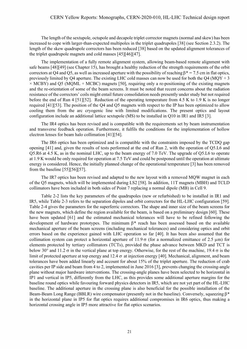
Table 2-2 lists the key parameters of the quadrupoles (new or refurbished) to be installed in IR1 andIR5, while Table 2-3 refers to the separation dipoles and orbit correctors for the HL-LHC configuration [59].Table 2-4 gives the parameters for the superferric correctors. The shape and inner size of the beam screens forthe new magnets, which define the region available for the beam, is based on a preliminary design [60]. Thesehave been updated [61] and the estimated mechanical tolerances will have to be refined following thedevelopment of hardware prototypes. The minimum E* reach has been assessed based on the availablemechanical aperture of the beam screens (including mechanical tolerances) and considering optics and orbiterrors based on the experience gained with LHC operation so far [40]. It has been also assumed that thecollimation system can protect a horizontal aperture of 11.9 V (for a normalized emittance of 2.5 Pm) forelements protected by tertiary collimators (TCTs), provided the phase advance between MKD and TCT isbelow 30° and 11.2 V in the vertical plane at top energy. Otherwise, for the rest of the machine, 19.4 V is thelimit of protected aperture at top energy and 12.4 V at injection energy [40]. Mechanical, alignment, and beamtolerances have been added linearly and account for about 15% of the triplet aperture. The reduction of crabcavities per IP side and beam from 4 to 2, implemented in June 2016 [3], prevents changing the crossing-angleplane without major hardware interventions. The crossing-angle planes have been selected to be horizontal inIP1 and vertical in IP5, differently from the LHC, as this provides some additional aperture margins for thebaseline round optics while favouring forward physics detectors in IR5, which are not yet part of the HL-LHCbaseline. The additional aperture in the crossing plane is also beneficial for the possible installation of theBeam-Beam Long Range (BBLR) wire compensator (presently not in the baseline). Conversely, squeezing E*in the horizontal plane in IP5 for flat optics requires additional compromises in IR6 optics, thus making ahorizontal crossing angle in IP5 more attractive for flat optics scenarios.

Machine layout and performance
22
The description of the shapes of the beam screens is made by providing the dimensions correspondingto the horizontal (H)/vertical (V) and 45° cuts for octagons; diameter (d) and gap (g) for rectellipses [50];radius for circles. The orientation of the rectellipse cross-section depends on the IP side and beam and it hasbeen chosen to optimise the beam aperture in collision. The alignment tolerances are represented as a racetrackshape of radius (R), horizontal (H), vertical (V) extent, respectively. The values provided include groundmotion and fiducialization tolerances [62], although they are going to be reviewed in the context of the fullremote alignment system.
Table 2-2: New or refurbished quadrupoles for the HL-LHC in IR1 and 5. “Beam stay clear” indicates theminimum aperture available for the beam considering the tolerance on the mechanical deformations of thenominal beam screen inner shape.
Inner triplet (single aperture) Matching section (two-in-one)Magnet Q1 Q2 Q3 Q4 Q5
Number per side per insertion 2 1Type MQXFA MQXFB MQXFA MQY MQMLMagnetic length (m) 4.2 7.17 4.2 3.4 4.8Maximum Gradient (T/m) 132.2 160 160Coil aperture (mm) 150 70 56Aperture separation (mm) NA 194Operating temperature (K) 1.9 4.5Beam screen shape Octagon RectellipseNominal beam screen aperture(mm)
99.7(H/V)/99.7(45°)
119.7(H/V)/110.7(45°) 60.2(d) / 50.4 (g) 47.5(d)/37.7(g)
Beam stay clear (mm) 94.94(H/V)/94.94(45°)
115.3(H/V)/106.3(45°) 57.8(d) / 48 (g) 45.1(d)/35.3(g)
Alignment tolerances(R/H/V) (mm) 0.6/1.0/1.0 0.84/1.26/0.6
Beam screen orientation(plane of smaller gap)
L.B1: VL.B2: HR.B1: HR.B2: V
Table 2-3: Separation and corrector dipole magnets for the HL-LHC in IR1 and 5. The order of the correctorshas to be considered starting from the IP.
Separation/recombinationdipoles Orbit correctors
Assembly D1 D2 CP Q2 D2 Q4 Q5Number per side perinsertion 1 1 1 2 2 3 1
Configuration HV nested HV nested
L.B1: VHL.B2: HVR.B1: VHR.B2: HV
consecutive
L.B1: VHVL.B2: HVHR.B1: HVHR.B2: VHVconsecutive
L.B1: VL.B2: HR.B1: HR.B2: V
Type MBXF MBRD MCBXFA MCBXFB MCBRD MCBY MCBC
Magnetic length (m) 6.27 7.78 2.2 1.2 1.93 0.9 0.9
Integrated field (T m) 35.08 35.08 4.5 2.5 5.0 2.5 2.33
CERN Yellow Reports: Monographs, CERN-2020-010, HL-LHC Technical design report
23
Assembly D1 D2 CP Q2 D2 Q4 Q5
Coil aperture (mm) 150 105 150 150 105 70 56Aperture separation(mm) NA 188 NA NA 188 194 194
Operatingtemperature (K) 1.9 4.5
Beam screen shape Octagon Octagon Octagon Octagon Octagon Rectellipse Rectellipse
Nominal beam screenaperture (mm)
119.7 (H/V)/110.7 (45°)
87.45 (H/V)/77.55 (45°)
119.7(H/V)/110.7 (45°)
119.7 (H/V)/110.7 (45°)
87.45 (H/V)/77.55 (45°)
60.2 (d) /50.4 (g)
47.5 (d)/37.7(g)
Beam stay clear 115.3 (H/V)/106.3 (45°)
82.7 (H/V)/72.5 (45°)
115.3(H/V)/106.3(45°)
115.3 (H/V)/106.3 (45°)
82.7 (H/V)/72.5 (45°)
57.8 (d) /48 (g)
45.1 (d)/35.3(g)
Alignment tolerances(R/H/V) (mm) 0.6/1.0/1.0 0.84/1.36/1.0 0.6/1.0/1.0 0.6/1.0/1.0 0.84/1.36/1.0 0.84/1.26/0.6
Beam screenorientation (plane ofsmaller gap)
L.B1: VL.B2: HR.B1: HR.B2: V
Table 2-4: New superferric correctors for the HL-LHC [38][39]. The order (from left to right) follows the orderof installation from the IP.
Number 1 1 1 1 1 1 1 1 1Number ofpoles 4 12 12 10 10 8 8 6 6
Normal/skew Skew Normal Skew Normal Skew Normal Skew Normal SkewName MQSXF MCTXF MCTSXF MCDXF MCDSXF MCOXF MCOSXF MCSXF MCSSXFMagneticlength (m) 0.401 0.470 0.099 0.146 0.146 0.145 0.145 0.167 0.167
Integrated field(mT m) at 50mm
700 86 17 37 37 69 69 95 95
Aperture (mm) 150Operatingtemp.(K) 1.9
Beam screenshape Octagon
Nominal beamscreen aperture(H/V) (mm)
119.7(H/V)/110.7(450)
Beam stayclear (mm)
115.3(H/V)/106.3(45°)
Alignmenttolerances(R/H/V) (mm)
0.6/1.0/1.0
As already mentioned, protection devices are required for the new layout of the IR1 and IR5 regions.The current LHC layout has a TAS in front of Q1, to protect this magnet from collision debris, and a TAN toprotect D2 from the neutrals produced at the IP. For the HL-LHC, these two devices will have to be upgradedto withstand much larger luminosities and to be suitable for the new layouts and flexible optics configurations.Furthermore, additional masks are envisaged to protect other magnets in the matching section. A summarywith the characteristics of these devices can be found in Table 2-5.

Machine layout and performance
24
Table 2-5: New absorbers for the HL-LHC. TAXS alignment tolerances include the IP displacement.Mechanical tolerances are not known yet therefore a conservative fiducialization tolerance has been used (2mm).
Inner triplet(single aperture)
Matching section(two-in-one)
Function Main secondaryabsorber
Main neutralabsorber Mask Q4 Mask Q5 Mask Q6
Aperture 1 2 2 2 2Type TAXS TAXN TCLMB TCLMB TCLMCL (m) 1.8 3.332 1.0Aperture separation (mm) NA 151–161 194Aperture shape Circle Circle RectellipseNominal aperture (mm) 60 85 60.2 (d)/50.4 (g) 60.2 (d)/50.4 (g) 47.5 (d)/37.7 (g)Beam stay clear (mm) 58 82 57.8 (d)/48 (g) 57.8 (d)/48 (g) 45.1 (d)/35.3 (g)Alignment tolerances(R/H/V) (mm) 2.0/2.5/2.5 0.84/1.36/1 0.6/1/1
Table 2-6 gives the main sets of E* values (including the optical parameters corresponding to the ionruns). Since IR2 and IR8 are running with increased strength of the triplets at injection, an optics transition isapplied before reaching top energy to reduce the required strength of the triplets. It is also planned to performthe squeeze down to כߚ = 64 cm (which is the initial value of the כߚ required to level at the nominal luminosityof 5 × 1034 cm-2s-1) in IP1 and IP5 for the high-luminosity IR optics and to כߚ = 1.5 m for Point 8 during theramp to minimize the turn-around time [30]. Additional optics scenarios for the end of the ramp with differentcombinations of כߚ and ATS factor are being studied to optimize the Landau damping and allow a smoothincrease of luminosity as required by the cryogenic system.
Table 2-6: Available optical configurations for the baseline layout. IR3 and IR7 are not included as they havestatic optics from injection to collision and do not take part in the ATS scheme. IR4 and IR6 take part in theATS and this is highlighted here, where the “No ATS” configuration corresponds to an injection-compatibleoptics kept constant up to top energy. The telescopic indexes [63] are indicated in parenthesis. Flat alternativeconfigurations are also shown, assuming V/H crossing in IP1/5, respectively.
Optics IR1 IR5 IR2 IR8 IR4 IR6Injection ȕ* = 6 m ȕ* = 6 m ȕ* = 10 m ȕ* = 10 m No ATS No ATSEnd of ramp ȕ* = 6 m ȕ* = 6 m ȕ* = 10 m ȕ* = 10 m No ATS No ATSPre-squeeze ȕ* = 50 cm ȕ* = 50 cm ȕ* = 10 m ȕ* = 1.5 m No ATS No ATS
Collision round ȕ*ATS = 15 cm ȕ*
ATS = 15 cm ȕ* = 10 m, ATS(3.33×, 3.33×)
ȕ* = 1.5 m, ATS(3.33×, 3.33×)
ATS(3.33×, 3.33×)
ATS(3.33×, 3.33×)
Collision ions ȕ* = 50 cm ȕ* = 50 cm ȕ* = 50 cm ȕ* = 1.5 m No ATS No ATSCollision VDM ȕ* = 30 m ȕ* = 30 m ȕ* = 30 m ȕ* = 30 m No ATS No ATS
Alternative configurations
Collision Flat ȕ*ATS =
7.5/30 cmȕ*
ATS =30/7.5 cm
ȕ* = 10 m, ATS(6.66×, 1.66×)
ȕ* = 1.5 m, ATS(6.66×, 1.66×)
ATS(1.66×, 6.66×)
ATS(1.66×, 6.66×)
Collision FlatCC ȕ*ATS =
7.5/18 cmȕ*
ATS =18/7.5 cm
ȕ* = 10 m, ATS(6.66×, 2.77×)
ȕ* = 1.5 m, ATS(6.66×, 2.77×)
ATS(2.77×, 6.66×)
ATS(2.77×, 6.66×)
2.3.2 Target field quality, dynamic aperture, and correction schemesThe Dynamic Aperture (DA) specifies the minimum stable amplitude in terms of RMS beam size over a givennumber of turns in the machine. It has been used since the initial steps of the design of the LHC [50] todetermine the required field quality of the various magnet classes. The methods used for DA computation in

CERN Yellow Reports: Monographs, CERN-2020-010, HL-LHC Technical design report
25
the HL-LHC are described in Refs. [12][37][50]. For reference, the multipole expansion used to describe themagnetic field is given as in Ref. [50]:
௬ܤ + ௫ܤ = ୰ܤ σ ( + i ) ቀ௫ା୧௬బቁଵஶ
ୀଵ , (2-2)
where ௫ܤ , ௬, andܤ ୰ܤ are the transverse magnetic field components and the reference field, respectively. Thecoefficients , are the skew and normal field components, and ݎ is the reference radius. The magneticerrors are split into three components, namely systematic (S), uncertainty (U), and random (R), such that agiven multipole is obtained by:
= ೄ + కଵ.ହ + ோೃߦ , (2-3)
where ߦ , ோߦ are Gaussian-distributed random variables cut at 1.5 ı and 3 ı, respectively. The ߦ variable isthe same for all magnets of a given class and manufacturer, but changes from seed to seed and for the differentmultipoles, whereas ோߦ also changes from magnet to magnet. In the numerical simulations, the best knowledgeof the measured magnetic errors is assigned to the magnets as installed, while, for the magnets that will bereplaced according to the upgrade plans, the expected error table, with statistical assignment of errors, is used.The expected field quality for the new HL-LHC magnets is reported in Annex A-7. Given the large aperture,estimates for the fringe fields have been provided for the triplet magnets and are used in simulations.
The layout HLLHCV1.0 [64] has been extensively used and it has been the reference for the DA studies,so far [37]. Given the CPU-time required for these studies, it is not always possible to keep them synchronisedwith the development and evolution of the layout. It is expected that the differences introduced by layout andoptics changes since HLLHCV1.0 should not have a significant impact on DA. Nonetheless, DA studies forHLLHCV1.4 are ongoing.
The minimum acceptable DA value differs between injection and collision energies. At injection, wherethe beam–beam effects can be neglected, the focus is on the impact of magnetic field quality. For the LHCdesign [50], a minimum DA value of 12 ı (for a normalized emittance of 3.75 ȝm) was assumed. The bestmodel of the LHC, including the measured field quality of the magnets and the magnets sorting, provides aDA slightly lower than 11 ı >��@, but no signs of DA-related limitations have been observed during operationor dedicated studies in Run 1 and Run 2. Hence, for the HL-LHC a target value of 12 ı has been assumed, butfor the lower nominal emittance of 2.5 ȝm.
At top energy, and in particular in collision, beam–beam effects are dominant and the DA has to beevaluated including magnetic field imperfections as well as head-on and long-range beam–beam effects (seeSection 2.4.2). Hence, the impact of the various multipolar errors on DA is first verified without beam-beameffects and eventually these effects are included, providing the final DA value, also verifying that the impactof field quality remains negligible in this configuration. Note that the acceptable minimum DA was set to 10 ı(for a normalized emittance of 3.75 Pm) at top energy for the LHC >��@. Based on the LHC experience theacceptance criteria for the field quality of the HL-LHC magnets have been defined to guarantee a minimumDA of 8 V (for a normalized emittance of 2.5 Pm) in the absence of beam-beam effects and of 6 V in collisionwhen beam-beam effects are included (see Section 2.4.2).
The simulation studies have confirmed that the target field quality at injection is consistent with the LHCDA target mentioned above for low values of the chromaticity (Q’ = + 3) and when the Landau Octupoles arenot powered. The expected field quality at high energy gives a minimum DA of about 8.5 ı (for the clockwiserotating beam - Beam 1) and 7.5 ı (for the anti-clockwise rotating beam - Beam 2) for the round optics at theminimum E* of 15 cm, provided that the field errors are properly compensated by the high-order tripletcorrectors [37]. The difference of DA between Beam 1 and 2 is already present for the LHC [65] and such adifference is observed also in the HL-LHC [37]. Note that the phase advances over the various insertions arenot the same for the two beams as well as the global phase advance between IP1 and IP5, which could explainthe differences in DA observed. Optimization of the DA by tuning of the phase advance between IP1 and IP5is being pursued [37]. Although the simulations including beam-beam effects (see Section 2.4.2) indicate that

Machine layout and performance
26
the operational scenario described in Ref. [30] is compatible with the target DA of 6 ı and this is dominatedby beam-beam, it is evident that a close follow-up of the field quality is mandatory and corrective actions arerequired in case of deviations from the expected one. In that respect, the analysis of the first measurements ofthe field quality on short models of the triplet quadrupoles, showing larger than expected a4 and b5 errors haveled to the increase of the length of the sextupole, octupole and decapole correctors (normal and skew), afteranalysis of the potential impact of these errors on DA [37][38]. The analysis of the effect of a larger thanexpected b6 error in the short models of the triplet quadrupoles has led to the decision to act on the MQXFcross-section to optimize b6 [66][67], rather than increasing the length of the corresponding corrector. Recentresults on the field quality of the D2 separation dipole and of the MCBRD correctors are being scrutinized todetermine whether mitigation measures are needed. The impact of the field quality of the MCBXF correctormagnets on DA is also being reviewed [68]. Note that the impact of the field quality of the 11 T dipoles on DAhas been assessed and found marginal [69].
The knowledge of the transfer functions of the higher-order correctors and of the optical functions attheir location has been found to be uncritical. Tolerance of ±1 mm in the relative alignment of the magneticaxis of the non-linear correctors with respect to that of the triplet magnets and of ±1 mrad in the roll angle ofthe non-linear correctors have been determined [37]. In the absence of multipolar correctors, the minimum DAwould be reduced down to about 5.5 ı (Beam 1) and 3.8 ı (Beam 2) [37]. Rapid commissioning of the machinedown to low E* will rely on accurate knowledge of the field errors and for that reason an accurate (down to0.05 units [45]) measurement of the field errors is vital. In addition, the development of strategies for beam-based measurement and correction of field errors is being pursued and actively tested in the LHC [70].
Preliminary estimates of the crab cavity field quality have been provided and are summarized in AnnexA-8. DA simulations indicate that the estimated field quality should be good enough to prevent any impact onDA [71][72][73]. Recently, the RF multipoles have been measured for the DQW cavities [69] and the impacton DA was assessed [74] and found to be negligible.
The correction of the linear optics poses significant challenges given the tight requirements, e.g. toensure a luminosity imbalance lower than 5% between IP1 and IP5, as has been requested in Ref. [75]. Tunestability of about 10-5 is needed to achieve the required accuracy of the E function at the IP using k-modulation[76]. The tune stability critically depends on the low frequency (<1 Hz) current stability in the main circuits asconfirmed by measurements in the LHC [77]. Extrapolations to the HL-LHC indicate the need of a furtherimprovement of the current stability of the main dipoles in the four sectors adjacent to the two high-luminosityexperiments where the telescopic squeeze is applied. The feasibility of such a scheme has been confirmed,although the corresponding upgrade is not included in the baseline yet [78]. Recently, a significantly lessdemanding power converter upgrade has been found with similar noise level in the low frequency region [79].In order to precisely determine the optics at the interaction point, K-modulation techniques need to be appliedon the first of the two magnets in the Q1 assembly. Hence, a trim circuit to modulate the current of the firstmagnet in Q1 has been added [77][78]. On the other hand, the trim circuit allowing to vary independently thecurrent circulating in the two magnets in the Q2 assembly has been suppressed based on the expected alignmenttolerances and the precision of the measurement of the transfer functions of the MQXF magnets [45]. The newtriplet circuit configuration is represented in Figure 6.4. Note that a detailed and global review of thespecifications of the new electrical circuits has been carried out recently [81].
The Nb3Sn technology features unavoidable thermo-magnetic instabilities, called flux jumps, that,coupled to the voltage and current control of the magnet, result in a change of the integrated magnetic field.Recent studies in the HL-LHC magnet prototypes suggest that flux jumps could lead to average variations inthe integrated magnetic field of about 0.002% within 46 ms [82] during the energy ramp. Simulations assumingthese preliminary values indicate that flux jumps during the energy ramp are not a concern for emittance growth[82] although orbit excursions could occasionally lead to beam dumps [83].

CERN Yellow Reports: Monographs, CERN-2020-010, HL-LHC Technical design report
27
2.4 Performance
2.4.1 Beam stabilityThe LHC effective impedance is larger at high energy, when the collimators become its dominant contributors,over a wide range of frequencies, because of their small gaps [84] and it can affect beam stability. Amongthem, the primary (TCP) and secondary collimators (TCSG) are the main contributors to the transverseimpedance and particularly those in the betatronic collimation section in LSS7, because of their smaller gaps.During Run 2, systematic measurements have been performed to characterize the present LHC impedancemodel. These agree with expectations, with an uncertainty that is estimated to be less than 50% [85][86][87].Concerning beam stability measurements through Landau octupoles, a good agreement was also obtained [88],but only when stability is considered on short time scales (shorter than few minutes). For longer time scales,typical of transition times between different phases of the cycle, noise sources acting on the beam and inducingdipolar oscillations at the level of 10-4 ı are observed to affect beam stability. The origin of this noise and themechanisms leading to transverse instabilities are being investigated [89][90][91][92].
During LS2, new low-impedance collimators will be installed to replace and enhance, with the additionof embedded beam position monitors, the functionality of the existing ones, as part of the HL-LHC andConsolidation Projects. During LS3, up to 5 additional low-impedance secondary collimators per beam will beinstalled, depending on the beam-based measurements during Run 3.
The impedance reduction with Mo-coated Mo-Gr collimators has been tested and validated throughextensive laboratory and beam-based measurements [85][86]. The resulting impedance reduction willguarantee transverse stability in all phases of the HL-LHC cycle, compatibly with the maximum strength ofthe Landau octupoles and the present performance of the transverse feedback in terms of damping time andbandwidth, still providing sufficient DA for large values of the chromaticity [85][93][94]. The scenarios foroperation at nominal and ultimate luminosity are described in Ref. [30] and they consider the experience gainedduring Run 1 and Run 2 [89][94][96][97]. The effects of beam coupling impedance, electron cloud, head-onand long-range beam-beam forces, realistic transverse feedback and machine optical parameters like tunes,linear coupling [98], linear and non-linear chromaticity, Landau octupole strength and other non-linearitiesand more recently the effect of noise [89][92][99] have been or are gradually being taken into account [2][12]and mitigated, still a factor 2 stronger Landau octupoles are required as compared to expectations.
Requirements on the ramp and acceleration rates of the dipole correctors determining the separationbump have been elaborated in order to guarantee transverse stability during the collapse of the separation bump[78][100].
Attention must be paid to the impedance of new pieces of equipment, in particular for those beinginstalled in regions with high E functions (e.g. crab cavities), which are enhancing the effects of transverseimpedance. Their design is being closely followed-up by the impedance team in collaboration with thedesigners. For the crab cavities, a limit of 1 M:/m (depending on the frequency) on the transverse shuntimpedance of each HOM has been chosen as a guideline to avoid that this equipment visibly affects thecorresponding stability thresholds, expressed by the additional Landau octupole strength required to stabilizethe corresponding transverse instabilities [101]. An overall description of the studies carried out and the statusof the guidelines concerning the design of new pieces of equipment to minimize impedance and thecorresponding actions is available in Ref. [84].
The operation with 25 ns beams relies heavily on beam-induced scrubbing and the pace of the intensityramp-up after LS1 (when practically all LHC beam screens and vacuum chambers were vented to air forinterventions) was determined by electron cloud effects, both from the implied heat load (see Section 2.4.3)and beam stability point of views [102][103], as expected. Although a significant reduction of the SecondaryElectron Yield (SEY) has been obtained during Run 2 through scrubbing, significant differences in the finalvalue of the SEY, inferred from measurements of the heat load, have been observed in different sectors, indifferent cryogenic cells and between magnets within the same sector and cryogenics cell, as a result of
Machine layout and performance
28
different surface properties [104][105][106]. Coherent beam instabilities are expected and observed [89] in theLHC at injection as a result of the residual electron cloud, in particular in the quadrupoles. Machine settingswith high chromaticity and Landau octupoles [30] are considered to be sufficient to stabilize the HL-LHCbeam, even assuming the same SEY pattern observed in Run 2, considering the non-monotonic dependence ofthe electron cloud density as a function of the bunch population [107][108][109][110][111].
Amorphous carbon coating of the beam screens of the superconducting magnets from the IP up to Q5(included) in IR1 and IR5 and of the triplet and D1 magnets in IR2 and IR8, as well as of the Q4, D2, Q5 andQ6 cold masses R2 and L8 is part of the baseline. This and the non-monotonic dependence of the electroncloud density on the bunch population should prevent electron cloud instabilities at high energy after scrubbingfor SEY < 1.3 and in particular at the higher bunch populations [110][111]. However, due to the non-monotonicdependence of the electron cloud on the bunch population, instabilities driven by e-cloud [112] could beobserved in the HL-LHC at the end of long physics fills (so-called “pop-corn instabilities”) due to the increaseof electron density in the centre of the dipole magnets as the bunch intensities become smaller. If this occurs,the beams can be stabilized by increasing the chromaticity up to 15-20 units [109].
The longitudinal beam parameters of the HL-LHC beams in collision listed in Table 2-1, and moregenerally those described in Ref. [30] for the various phases of the HL-LHC cycle, have been updated withrespect to those listed in Ref. [3] to guarantee the longitudinal beam stability.
2.4.2 Beam–beam effectsThe beam–beam interaction is known to be an important factor limiting the performance reach of presentparticle colliders [12]. Beam–beam interactions induce particle losses, beam size blow-up and an increase inthe beam halo population and therefore lower luminosity lifetime, due to crossing of excited resonances,enhanced by the large beam-beam tune-spread and by noise. The rapid depletion of the beam halo when goingin collision because of the sudden reduction of the DA can lead to loss spikes and unwanted beam dumpstaking into account that the energy stored in the beam halo particles above 3.5 V is expected to reach 35 MJ inthe HL-LHC assuming the same halo densities measured in the LHC during Run 1 and Run 2. For that reason,it has been proposed to install hollow-electron lenses to control halo population down to 3 to 4 ı during thewhole cycle. The resulting transverse beam distribution has been considered in the definition of the operationalscenario [30].
In the evaluation of the HL-LHC, the criteria used for establishing satisfactory beam dynamics behaviourduring operation with beam collisions were similar to those in the LHC design study. The target value for theone-million turn DA is 6 ı for operation (for the nominal HL-LHC emittance of 2.5 ȝm) or more for a particlewith relative momentum deviation of 2.7 × 10í4, in order to guarantee that the beam lifetime is dominated byluminosity burn-off. The motivation for the choice is explained in Ref. [113] and it has been validated withexperiments in the LHC [21][114][115][116].
Multi-parametric DA studies have validated the operational scenario [30] both for nominal and ultimateluminosity with a constant total crossing angle of 500 Prad in IP1 and 5, including the margins for reducing itduring the collision process, through tune optimisation [22][117][118]. Operation at high-luminosity of LHCb(1.5 × 1034 cmí2 sí1) appears also to be compatible with the above DA target, although it might limit thepossibility of further optimizing the crossing angle throughout the levelling phase by reducing it further forE* > 15 cm as indicated in Ref. [3]. PACMAN effects have been evaluated and shown not to have a significantimpact on DA and luminosity [119].
A more significant mechanism of emittance degradation can be related to the interplay between thenonlinearity of the beam–beam interaction and various sources of noise. The effects of the ripple in the phaseand amplitude of crab cavities and in the current of magnet power supplies have been studied. Current estimatesfor white random phase and relative voltage amplitude noises in the crab cavities, suggest RMS values of3.4 × 10í5 rad and 4.9 × 10í5, respectively [120]. This would cause an integrated luminosity loss of about 2%for the baseline scenario in the presence of a transverse feedback with a damping time of 50 turns
CERN Yellow Reports: Monographs, CERN-2020-010, HL-LHC Technical design report
29
[120][121][122][123]. Nevertheless, recent measurements in the SPS suggest that these estimates could be toopessimistic by about a factor 2 or 3 [124]. The main specification for the crab cavities including expected multi-pole components [74] are summarized in Annex A-8.
Magnet power converter current noise can also lead to an increase of losses and emittance blow-up. Therequirements have been summarized in Refs. [80][125][126][127][128]. The observed noise on the dipole mainpower converters at frequencies between 7-8 kHz is of concern, its origin is not yet clear and its amplitudeshould be reduced in view of the HL-LHC to avoid any significant reduction of the DA [126][127].
The concept of beam-beam long range compensation by means of current bearing wires [117][129][130][131] has been successfully demonstrated in the LHC [132][133] and could enhance the HL-LHC performanceallowing a reduction of the crossing angle for the baseline scenario [134][135][136] or open the way toalternative scenarios (see Section 2.5). Although not in the baseline, possible implementations are beingstudied and a space reservation between Q4 and Q5 has been granted.
2.4.3 Beam-induced heat loadThe circulating beam can deposit a significant amount of power on the structures exposed to it mainly throughthree different mechanisms: synchrotron radiation, impedances, and electron cloud. The impedance-inducedheat loads with the HL-LHC beam parameters [16] have been summarized in Ref. [84] for several key systems.The design of the various components is being closely followed-up and at present no showstoppers have beenidentified for the HL-LHC operation. In the analysis, it is assumed that no forward physics detectors will beinstalled during the HL-LHC era. This might have to be reviewed if proposals for forward physics at the HL-LHC will be submitted.
In the superconducting arcs, an important contribution to the heat load on the beam screens is given bysynchrotron radiation, which amounts to 1.92 kW/arc for HL-LHC beam parameters, whereas the longitudinalimpedance of the beam screen introduces a further contribution of 1.90 kW/arc.
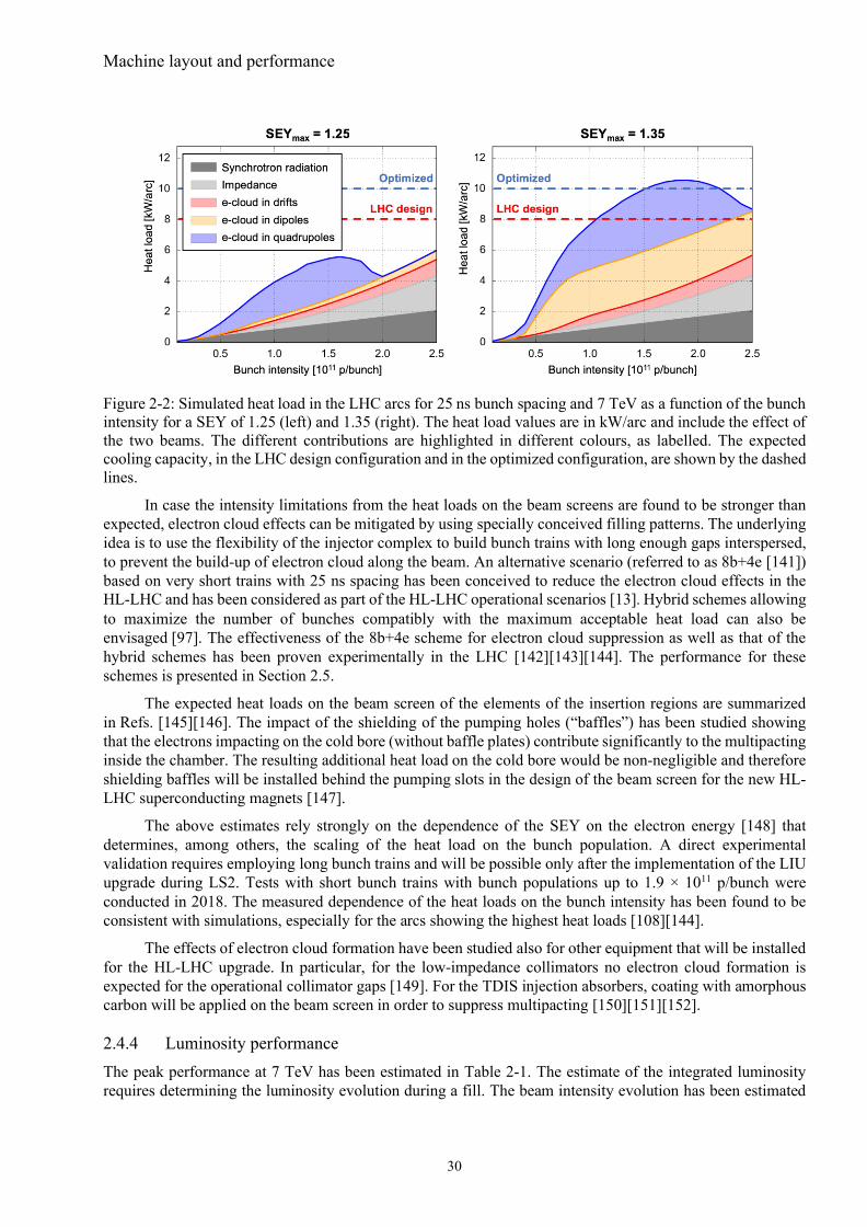
The remaining contribution from electron cloud will depend on the SEY of the beam screen surface thatcan be achieved through beam-induced scrubbing. Although a significant reduction of the SEY has beenobtained through scrubbing during Run 2, significant differences in the final value have been observed indifferent sectors [104][105][106]. Figure 2-2 shows the simulated beam induced heat load on the beam screensof the LHC arcs for the nominal 25 ns bunch pattern at 7 TeV, as a function of the bunch population, for aSEYmax parameter of 1.25 and 1.35, respectively. Details about the simulation model can be found inRef. [138]. The contributions to the heat deposition given by the impedance of the beam screen, the synchrotronradiation and the electron cloud in the different magnets have been displayed separately in different colours.The chosen SEY values of 1.25 and 1.35 correspond to the estimated values of SEY in the best (S34) and worst(S12) sectors, based on heat load measurements taken in Run 2 (August 2017, average over the arc) [139]. Thecooling capacity provided by the cryogenic system for the arc beam-screens is expected to be 8 kW/arc(corresponding roughly to 160 W/half-cell) in the design cryogenic configuration. During Run 2, the LHCcryogenic system has been operated in an optimized configuration (using one cold-compressor unit to servetwo consecutive sectors) profiting from the lower than expected heat loads on the cold masses at 1.9 K. Thecompatibility of this optimized configuration with the HL-LHC operational scenarios is being verified. Withthis optimized configuration, a higher cooling capacity becomes available for the arc beam screens [140], asindicated by the blue line in Figure 2-2, which is very close to the heat load expected for the sectors showinghigher SEY (Figure 2-2 right).
Machine layout and performance
30
Figure 2-2: Simulated heat load in the LHC arcs for 25 ns bunch spacing and 7 TeV as a function of the bunchintensity for a SEY of 1.25 (left) and 1.35 (right). The heat load values are in kW/arc and include the effect ofthe two beams. The different contributions are highlighted in different colours, as labelled. The expectedcooling capacity, in the LHC design configuration and in the optimized configuration, are shown by the dashedlines.
In case the intensity limitations from the heat loads on the beam screens are found to be stronger thanexpected, electron cloud effects can be mitigated by using specially conceived filling patterns. The underlyingidea is to use the flexibility of the injector complex to build bunch trains with long enough gaps interspersed,to prevent the build-up of electron cloud along the beam. An alternative scenario (referred to as 8b+4e [141])based on very short trains with 25 ns spacing has been conceived to reduce the electron cloud effects in theHL-LHC and has been considered as part of the HL-LHC operational scenarios [13].Hybrid schemes allowingto maximize the number of bunches compatibly with the maximum acceptable heat load can also beenvisaged [97]. The effectiveness of the 8b+4e scheme for electron cloud suppression as well as that of thehybrid schemes has been proven experimentally in the LHC [142][143][144]. The performance for theseschemes is presented in Section 2.5.
The expected heat loads on the beam screen of the elements of the insertion regions are summarizedin Refs. [145][146]. The impact of the shielding of the pumping holes (“baffles”) has been studied showingthat the electrons impacting on the cold bore (without baffle plates) contribute significantly to the multipactinginside the chamber. The resulting additional heat load on the cold bore would be non-negligible and thereforeshielding baffles will be installed behind the pumping slots in the design of the beam screen for the new HL-LHC superconducting magnets [147].
The above estimates rely strongly on the dependence of the SEY on the electron energy [148] thatdetermines, among others, the scaling of the heat load on the bunch population. A direct experimentalvalidation requires employing long bunch trains and will be possible only after the implementation of the LIUupgrade during LS2. Tests with short bunch trains with bunch populations up to 1.9 × 10¹¹ p/bunch wereconducted in 2018. The measured dependence of the heat loads on the bunch intensity has been found to beconsistent with simulations, especially for the arcs showing the highest heat loads [108][144].
The effects of electron cloud formation have been studied also for other equipment that will be installedfor the HL-LHC upgrade. In particular, for the low-impedance collimators no electron cloud formation isexpected for the operational collimator gaps [149]. For the TDIS injection absorbers, coating with amorphouscarbon will be applied on the beam screen in order to suppress multipacting [150][151][152].
2.4.4 Luminosity performanceThe peak performance at 7 TeV has been estimated in Table 2-1. The estimate of the integrated luminosityrequires determining the luminosity evolution during a fill. The beam intensity evolution has been estimated

CERN Yellow Reports: Monographs, CERN-2020-010, HL-LHC Technical design report
31
by calculating the burn-off due to luminosity with a cross-section of 111 mb corresponding to the total cross-section [5].
The emittance evolution has been determined including intra-beam scattering (IBS) and radiationdamping. A finite difference method in steps of 10 min has been implemented to model the beam parametersduring a physics fill [123]. Figure 2-3 shows the evolution of the main parameters for the nominal and ultimatescenarios for the standard filling scheme with parameters listed in Table 2-1. The crossing angle is assumed tobe constant during the fill. E levelling has been considered as levelling mechanism and it has been appliedwhen the pile-up deviates by more than 2% from the target value. Levelling by separation (with full separationssmaller than 0.6 V at IP1 and IP5) can be used between E* levelling steps to minimize the number of opticssteps to about 10. Alternative matching schemes are also being studied to guarantee controlled opticstransitions that minimize E-beating during ramp, squeeze and during levelling [153]. It is also assumed thatlongitudinal blow-up is applied to keep the longitudinal emittance and RMS bunch length constant throughoutthe fill which results in a q-Gaussian density distribution in the longitudinal direction [123].
Figure 2-3: Evolution of the main beam and machine parameters for the nominal and ultimate scenarios.

Machine layout and performance
32
2.5 Alternative operational scenarios
The HL-LHC project includes the study of various alternatives to the present baseline configuration with theaim either of improving the potential performance or of providing options for addressing possible limitationsor changes in parameters [123]. These are briefly described in the following Sections and summarized in Table2-7.
2.5.1 8b+4e and hybrid filling schemesThe 8b+4e filling scheme [141] consists of PS trains of 56 bunches, providing similar bunch parameters as theother 25 ns schemes with about 30% fewer bunches. The four empty slots are expected to highly suppress theformation of the electron cloud, as discussed in Section 2.4. The lower number of bunches of the 8b+4e schemeimplies a lower peak luminosity at the same number of pile-up events per crossing, P. The single bunchparameters evolve as for the baseline during the physics fill. Therefore, integrated luminosity simply scaleslinearly with the number of bunches. To maximize luminosity, it is possible to mix 8b+4e trains with BCMSones to adapt the heat-load to the available cryogenic power.
2.5.2 Other filling schemesThe number of bunches in the PS trains could be increased from 72 to 80 in order to increase the integratedluminosity without affecting peak pile-up density [154]. In Ref. [155], various fillings schemes have beenconsidered offering an increase in integrated luminosity above 1.9% for all IPs. The only drawback of the 80-bunch filling scheme is the slightly larger number of bunches per injection (from 288 to 320) to be consideredfor machine protection matters in the SPS and the TI2 and TI8 transfer lines.
2.5.3 Flat optics with crab cavitiesA flat optics might be used with E of 7.5 cm and 18 cm in the separation and crossing planes, respectively, toimprove the performance. The achievement of the above E* might require the change of the crossing plane inIP1 and IP5 with respect to the present baseline unless significant improvements on tolerances are achieved.A normalized beam-beam long range separation of 11.4 ı could be reached at the end of the fill for bunchpopulations of 1.1 × 10¹¹ p/bunch applying approximate scaling from DA studies [117][156][157][158]. Theoperation at ultimate luminosity might not be possible unless E is increased or beam-beam long-rangecompensation schemes are implemented. The performance for this configuration is shown in Figure 2-4 and itexceeds the HL-LHC nominal performance in terms of integrated luminosity and pile-up density. Furtherstudies are necessary to validate the performance of this configuration.
2.5.4 Flat optics without crab cavitiesAlthough crab-cavities have been successfully operated with beam in the SPS [159][160], a back-up scenariohas been developed in case of a major crab cavity RF failure in the HL-LHC. In this scenario, it is possible topartially recover the performance loss by resorting to flat optics with larger beam size in the crossing plane atthe IP. The IP E functions that maximize luminosity are 7.5 cm and 31.5 cm. These E functions will requirethe change of the crossing plane in IP1 and IP5 with respect to the present baseline unless significantimprovements on tolerances are achieved. Current bearing wires [117][131][132][133][134][135][136] couldcompensate for the long-range interactions allowing for a reduction of the crossing angle and thereforeincreasing the luminous region. Without any mitigation, i.e. keeping round optics and no compensating wires,the nominal integrated luminosity would decrease by 13% with double peak pile-up density in case of a crabcavity failure. In the ultimate levelling scenario, the performance would drop by 23% with a peak pile-updensity reaching 4.1 events/mm in such an event.
Assuming flat optics, the absence of crab cavities reduces the performance by 5% in the nominal and12% in the ultimate scenarios. The beam-beam long-range compensation could allow reducing the normalized
CERN Yellow Reports: Monographs, CERN-2020-010, HL-LHC Technical design report
33
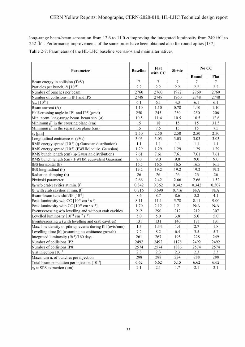
long-range beam-beam separation from 12.6 to 11.0 V improving the integrated luminosity from 249 fb-1 to252 fb-1. Performance improvements of the same order have been obtained also for round optics [137].
Table 2-7: Parameters of the HL-LHC baseline scenarios and main alternatives.
Parameter Baseline Flatwith CC 8b+4e No CC
Round FlatBeam energy in collision (TeV) 7 7 7 7 7Particles per bunch, N [1011] 2.2 2.2 2.2 2.2 2.2Number of bunches per beam 2760 2760 1972 2760 2760Number of collisions in IP1 and IP5 2748 2748 1960 2748 2748Ntot [1014] 6.1 6.1 4.3 6.1 6.1Beam current (A) 1.10 1.10 0.78 1.10 1.10Half-crossing angle in IP1 and IP5 (ȝrad) 250 245 250 250 206Min. norm. long-range beam–beam sep. (ı) 10.5 11.4 10.5 10.5 12.6Minimum ȕ* in the crossing plane (cm) 15 18 15 15 31.5Minimum ȕ* in the separation plane (cm) 15 7.5 15 15 7.5Hn [ȝm] 2.50 2.50 2.50 2.50 2.50Longitudinal emittance İL (eVs) 3.03 3.03 3.03 3.03 3.03RMS energy spread [10-4] (q-Gaussian distribution) 1.1 1.1 1.1 1.1 1.1RMS energy spread [10-4] (FWHM equiv. Gaussian) 1.29 1.29 1.29 1.29 1.29RMS bunch length (cm) (q-Gaussian distribution) 7.61 7.61 7.61 7.61 7.61RMS bunch length (cm) (FWHM equivalent Gaussian) 9.0 9.0 9.0 9.0 9.0IBS horizontal (h) 16.5 16.5 16.5 16.5 16.5IBS longitudinal (h) 19.2 19.2 19.2 19.2 19.2Radiation damping (h) 26 26 26 26 26Piwinski parameter 2.66 2.42 2.66 2.66 1.52R0 w/o crab cavities at min. E* 0.342 0.362 0.342 0.342 0.507R1 with crab cavities at min. E* 0.716 0.690 0.716 N/A N/ABeam–beam tune shift/IP [10-3] 8.6 8.7 8.6 3.2 4.1Peak luminosity w/o CC [1034 cm-2 s-1] 8.11 11.1 5.78 8.11 9.00Peak luminosity with CC [1035 cm-2 s -1] 1.70 2.12 1.21 N/A N/AEvents/crossing w/o levelling and without crab cavities 212 290 212 212 307Levelled luminosity [1034 cmí2 sí1] 5.0 5.0 3.8 5.0 5.0Events/crossing P (with levelling and crab cavities) 131 131 140 131 131Max. line density of pile-up events during fill (evts/mm) 1.3 1.34 1.4 2.7 1.8Levelling time [h] (assuming no emittance growth) 7.2 8.2 6.4 3.5 5.7Integrated luminosity (fb-1)/160 days 261 267 195 228 249Number of collisions IP2 2492 2492 1178 2492 2492Number of collisions IP8 2574 2574 1886 2574 2574N at injection [1011] 2.3 2.3 2.3 2.3 2.3Maximum n. of bunches per injection 288 288 224 288 288Total beam population per injection [1013] 6.62 6.62 5.15 6.62 6.62Hn at SPS extraction (ȝm) 2.1 2.1 1.7 2.1 2.1

Machine layout and performance
34
Figure 2-4: Summary chart showing integrated luminosity per year versus effective pile-up density for thevarious scenarios considered. The impact of assuming less conservatively a cross-section of 81 mb (inelasticcross-section) instead of 111 mb (total cross-section), for the estimate of the burn-off lifetime is also shown,(height of the boxes) indicating the importance of minimizing losses due to reduced DA and the potential gainin integrated luminosity.
2.6 The HL-LHC as a nucleus–nucleus collider
The LHC’s second major physics programme provides nucleus–nucleus (fully stripped lead ions 208Pb82+) andproton–nucleus collisions to ALICE, ATLAS and CMS, during typically about one month per year and up toLS4 in the current HL-LHC baseline schedule. All upgrades of the injectors, collider (upgrade of thecollimation system described in Chapter 5) and experiments relevant to this heavy-ion programme are expectedto be implemented during LS2, so the full “HL-LHC” performance is considered to be already available inRun 3. It should be noted that LHCb has also taken heavy-ion data since the 2012 p-Pb pilot run and 2015 Pb-Pb Run and is expected to continue to take data after LS2 and during the HL-LHC operating period.
The overall goals of the programme were initially set according to Ref. [161]. The central componentwas the accumulation 13 nbí1 of Pb-Pb luminosity in the ALICE experiment between LS2 and LS4 at a(levelled) peak luminosity of 7 × 1027 cm-2 s-1 [162][163][164][165]. Similar luminosities would be deliveredto ATLAS and CMS with filling schemes adjusted to provide a smaller level to LHCb, where a target of2 nb-1 is set [166]. The presently approved CERN planning also includes a short p-Pb run (whose goals werealready far exceeded in 2016) and a p-p reference run before the end of LHC Run 4 in 2030. Although nofurther heavy-ion runs beyond Run 4 are approved yet, a revised proposal for Runs 3 and 4 and plans to extendthe LHC nuclear programme beyond Run 4 have been formulated [166] and are presently under review. Anextension of the ion program beyond Run 4 will evidently reduce the time available for proton-proton operationand will thus imply a reduction of the performance reach of the HL-LHC. These new plans envisage a similarPb-Pb luminosity but more time spent on p-Pb and p-p reference runs and also collisions of lighter nuclei,e.g. Ar, O or Kr [166][167] with the potential to reach higher nucleon-nucleon luminosities. The acceleratorand injector scenarios for these lighter ion species remain to be worked out in detail.
In 2018, an integrated Pb-Pb luminosity of 1.8 nb-1 was reached in ATLAS and CMS (c.f., the ~ 3 nb-1
per one-month run that would achieve the HL-LHC goals), 0.9 nb-1 in ALICE and 0.23 nb-1 in LHCb. Thisexcellent performance was made possible through many improvements in the LHC and the injector chain. Inparticular, the average colliding bunch intensity was up to about 2.3 × 10⁸ Pb/bunch, which is more than 3 timesthe LHC design value. Peak luminosities of more than 6.1 × 1027 cm-2 s-1 were achieved in ATLAS and CMS,which is a factor 6 larger than the nominal peak luminosity [50] and almost at the HL-LHC target. ALICE andLHCb were levelled at the LHC design value of 1 × 1027 cm-2 s-1. This was the intrinsic limit of detector
CERN Yellow Reports: Monographs, CERN-2020-010, HL-LHC Technical design report
35
saturation for ALICE during Run 2. The detector upgrade to be implemented in LS2 aims to increase this limitby enabling a 50 kHz event rate [161] and it is therefore assumed that luminosity levelling can be performedat 6.4 × 1027 cm-2 s-1. Thanks to the special bunch spacing of 75 ns used in 2018, many more colliding bunch-pairs could be given to LHCb compared to operation with the usual 100 ns. This required LHCb luminositylevelling at the same value as ALICE for reasons of quench mitigation and luminosity sharing. While the LHCcould already provide peak luminosities close to the HL-LHC design, the integrated luminosity per run mustbe increased to reach the requested target in the available time. Since optics and bunch intensities in 2018reached or exceeded already the HL-LHC specifications, slip-stacking [168], enabled by the LS2 upgrades ofthe low-level RF system in the SPS, remains as the last significant upgrade to be implemented for the heavy-ion programme. Slip-stacking will increase the total number of circulating bunches from the current 733bunches with 75 ns bunch spacing to 1240 bunches spaced by 50ns.
The increased peak luminosity in the ALICE experiment will significantly increase the local beam lossesin IR2 after LS2. Ultra-peripheral electromagnetic interactions of colliding Pb nuclei create secondary beamswith altered magnetic rigidity emerging from the collision points. These are lost locally in the downstreamdispersion suppressor. The most critical one (bound-free pair production – BFPP) carries a significant powerthat can quench the impacted magnet [169][170][171][172]. The resulting luminosity limit in IR1 and IR5 ismitigated through local orbit bumps that deviate these losses into the empty connection cryostat. This techniquewas successfully proven close to the HL-LHC design luminosity in the 2018 Pb-Pb run. In IR2 this methoddoes not work because of the opposite quadrupole polarities. Instead installation of new collimators (TCLD)on the outgoing beam on each side of the ALICE experiment will allow the losses to be safely absorbed, asdiscussed in more detail in Chapter 5.
The collimation of nuclear beams has been demonstrated to be about two orders of magnitude worsethan for protons because of the more complicated nuclear interactions with collimators [173][174][175][176].This could lead to beam dumps or magnet quenches in case of sudden beam losses. To increase the collimationefficiency and withstand a temporary drop of the beam lifetime to 12 minutes with the full HL-LHC intensity,new TCLD collimators will be installed in the dispersion suppressors of IR7, as described in detail in Chapter 5.Each TCLD in IR7 will be part of a 15 m assembly, containing two new 11 T dipoles with the TCLD in themiddle, which will replace a present main dipole. A system of Crystal collimators will also be installed as anadditional measure.
The HL-LHC baseline parameters for Pb beams are summarised in Table 2-8. These parameters, initiallygiven in Ref. [164] and later updated in Ref. [165] and further in Ref. [177], apply to both Run 3 and Run 4,where the performance will be similar. The luminosity performance in a single fill has been simulated in Ref.[177] using two independent codes, the Collider Time Evolution program [178] and the Multi-BunchSimulation [179], assuming colliding Pb-Pb beams in all experiments and different options for how theluminosity is shared between them through the filling scheme. The time evolution of the luminosity is shownin Figure 2-5. With an average turnaround of about 200 min, the optimum fill length is about 4 h for the studiedscenarios. Assuming an operational efficiency of 50% (defined in Refs. [14] [3]) an integrated luminosity of2.2 - 2.8 nb-1 over a 24-day Pb-Pb physics run is expected at ATLAS, ALICE, and CMS, depending on fillingscheme, and up to 0.5 nb-1 at LHCb. With these assumptions, the HL-LHC target of 13 nb-1 at the end of Run4 can be met in about five Pb-Pb runs. It should be noted that meeting this target relies on the 50 ns bunchscheme and hence on the successful implementation of slip-stacking in the SPS. As a backup scheme, the 75ns scheme deployed in 2018 could be used, which would cause a decrease in integrated luminosity by 30-40%.
Operation with p-Pb was not foreseen in the original LHC design but, in the meantime, it has beensuccessfully demonstrated in the LHC [180]. For the HL-LHC, the Pb beam in Table 2-8 is assumed, matchedwith a proton beam of the same filling scheme and about 3 × 10¹⁰ protons per bunch. The same optics as forthe Pb-Pb runs are used. The luminosity is assumed to be levelled in ALICE at 5 × 1029 cm-2 s-1, while nolevelling is needed in ATLAS and CMS. The luminosity evolution has been simulated for a single fill as shownin Figure 2-6. Assuming an operational efficiency of 50% during a typical 24-day run, a total integrated

Machine layout and performance
36
luminosity of 0.53 - 0.68 pb-1 is reached in ATLAS and CMS depending on filling scheme, about 0.31 pb-1 inALICE, and up to about 0.15 pb-1 in LHCb.
Table 2-8: Key LHC design parameters for Pb operation from Ref. [177] compared with the achievedparameters in 2018 and the HL-LHC design values.
ParametersNominal LHC(design report)
2018 achievedHL-LHC
(LIU baseline)Beam energy in collision (Z TeV) 7 6.37 7Particles per bunch, N [107] 7 23 18Number of bunches per beam 592 733 1240Colliding pairs at IP1/5 < 592 733 976 - 12401
Colliding pairs at IP2 592 702 976 - 12001
Colliding pairs at IP8 0 468 0-7161
Total intensity Ntot [109] 41.4 169 223Beam current (mA) 6.12 24.9 33.0Stored beam energy (MJ) 3.8 13.9 20.5Minimum ȕ* (m) 0.5 0.5 0.5Normalized emittance İn (ȝm) 1.5 2.3 1.65Longitudinal emittance İL (eVs/charge) 2.50 2.33 2.42RMS energy spread [10-4] 1.08 1.06 1.02RMS bunch length (cm) 8.07 8.24 8.24Half-crossing angle at IP2 (µrad) (external,net) 110,40 137,60 170,100Peak luminosity [1027 cmí2 sí1] 1.0 - -Levelled luminosity IP1/5 [1027 cmí2 sí1] - 6.13 6.4Levelled luminosity IP2 [1027 cmí2 sí1] - 1.0 6.4Levelled luminosity IP8 [1027 cmí2 sí1] - 1.0 1.0Typical levelling time IP2 (h) - 7 1.5Maximum number of bunches per injection 54 42 56
1The values give the range over the filling schemes considered in Ref. [177].
Figure 2-5: The Pb-Pb luminosity evolution over time [177], simulated with the CTE code [178], in the ATLASand CMS experiments (left), in ALICE (middle) and in LHCb (right) for a typical fill in the HL-LHC, assumingthe baseline parameters in Table 2-8. Each line represents a different filling scheme from [177], named by theconvention where the first number shows the total number of bunches, the second number the collisions atIP1/5, the third number the collisions at IP2 and the last number the collisions at LHCb.

CERN Yellow Reports: Monographs, CERN-2020-010, HL-LHC Technical design report
37
Figure 2-6: The p-Pb luminosity evolution [177], simulated with the MBS code [179], in the ATLAS and CMSexperiments (left), in ALICE (middle) and in LHCb (right) for a typical p-Pb fill in HL-LHC. It is assumedthat ALICE is levelled at 5 × 1029 cm-2s-1, while no levelling is applied in the other experiments. Each linerepresents a different filling scheme from [177], named by the convention where the first number shows thetotal number of bunches, the second number the collisions at IP1/5, the third number the collisions at IP2 andthe last number the collisions at LHCb.
2.7 References[1] G. Apollinari, I. Bejar Alonso, O. Brüning, M. Lamont, L. Rossi, eds., High-luminosity Large Hadron
Collider (HL-LHC): Preliminary Design Report, DOI: 10.5170/CERN-2015-005.[2] O. Brüning, L. Rossi, eds., The High-luminosity Large Hadron Collider: the new machine for
illuminating the mysteries of Universe, Advanced Series on Directions in High Energy Physics: Volume24 (2015), World Scientific, DOI: 10.1142/9581.
[3] G. Apollinari, I. Bejar Alonso, O. Brüning, P. Fessia, M. Lamont, L. Rossi, L. Tavian (Eds.) High-Luminosity Large Hadron Collider (HL-LHC): Technical Design Report V.0.1, DOI: 10.23731/CYRM-2017-004.
[4] L. Rossi, Short recap of recent changes to baseline, 16th HL-LHC Parameter and Layout CommitteeMeeting, 16th July 2015, EDMS: 1567268.
[5] The ATLAS and CMS Collaborations, Expected pile-up values at HL-LHC, 30 September 2013, 2013,ATL-UPGRADE-PUB-2013-014.
[6] R. Tomás Garcia et al., Experimental Data Quality, 8th HL-LHC Collaboration Meeting, 15-18 October2018, CERN, INDICO: 742082.
[7] R. Tomás Garcia et al., Experimental Data Quality Working Group Indico Page, INDICO: 7932.[8] R. Jacobsson, Future wishes and constraints from the experiments at the LHC for the proton–proton
programme, ICFA Mini-Workshop on Beam-Beam Effects in Hadron Colliders (BB2013), CERN,Geneva, Switzerland, 18 - 22 Mar 2013, Eds. W. Herr and G. Papotti, DOI: 10.5170/CERN-2014-004.167.
[9] The LHCb Collaboration, Physics Case for an LHCb Upgrade II, CERN-LHCC-2018-027.[10] M. Deile on behalf of the CMS collaboration, CMS Forward Physics Detectors: Plans for HL-LHC, 8th
HL-LHC Collaboration Meeting, 15-18 October 2018, CERN, INDICO: 742082.[11] W. Herr, B. Muratori, Concept of Luminosity, CAS – CERN Accelerator School: Intermediate Course
on Accelerator Physics, Zeuthen, Germany, 15-26 Sep 2003, DOI: 10.5170/CERN-2006-002.361.

Machine layout and performance
38
[12] O. Brüning, L. Rossi, eds., The High-luminosity Large Hadron Collider: the new machine forilluminating the mysteries of Universe, 2nd Edition, Advanced Series on Directions in High EnergyPhysics: Volume XX (20XX), World Scientific. (Pending publication)
[13] G. Arduini, O. Brüning, R. De Maria, R. Garoby, S. Gilardoni, B. Goddard, B. Gorini, M. Meddahi, G.Rumolo and R. Tomás Garcia, Beam parameters at LHC injection,2014, CERN-ACC-2014-0006.
[14] B. Todd, LHC & Injectors, availability Run 2, 9th Evian Workshop on LHC Beam Operation, Evian,France, 30 January-1 February 2019, INDICO: 751857.
[15] R. Tomás Garcia, Update of HL-LHC parameters and operational scenarios (protons), 104th TechnicalCoordination Committee, 28th May 2020, INDICO: 921722.
[16] HL-LHC Technical Coordination Committee Parameter Table v. 7.1.1 (29/07/2020) HL-LHC ParameterTable
[17] D. Contardo, private communication, 3 December 2014.[18] J. Coupard, H. Damerau, A. Funken, R. Garoby, S. Gilardoni, B. Goddard, K. Hanke, A. Lombardi, D.
Manglunki, M. Meddahi, B. Mikulec, G. Rumolo, E. Shaposhnikova, M. Vretenar, eds., LHC InjectorsUpgrade, Technical Design Report – Volume I: Protons, 2014, CERN-ACC-2014-0337.
[19] G. Rumolo et al., LIU baseline for protons, LHC Performance Workshop 2017, Chamonix, France, 23–27 January 2017, INDICO: 580313.
[20] Y. Papaphilippou et al., Long Range Beam-Beam effects for HL-LHC, LHC Performance Workshop2018, Chamonix, France, 29 January – 2 February 2018, INDICO: 676124.
[21] D. Pellegrini et al., Incoherent beam-beam effects and lifetime optimization, 8th Evian Workshop onLHC Beam Operation, Evian, France, 12-14 December 2017, INDICO: 663598.
[22] N. Karastathis and Y. Papaphilippou, Beam-beam simulations for optimizing the performance of theHigh-luminosity Large Hadron Collider Proton Physics, 2020, CERN-ACC-NOTE-2020-0026.
[23] G. Arduini, S. Redaelli, HL–LHC ECR Optics configuration change, EDMS: 1832081.[24] R. Tomás Garcia et al., HL-LHC beam parameters for protons, LHC Performance Workshop 2017,
Chamonix, France, 23–27 January 2017, INDICO: 580313.[25] R. De Maria et al., What can be learnt in Run 2 for Run 3 and HL-LHC runs?, Proc. of the 7th Evian
Workshop, 13-15 December 2016, Evian, France, Eds. S. Dubourg, B. Goddard, G. Trad, CERN-ACC-2017-094, pp. 255-264.
[26] Minutes of the LIU-SPS BLPTL WG Meeting, 8th November 2017, INDICO: 671463.[27] E. Shaposhnikova, J.E. Müller, Bunch length and particle distribution for (HL-)LHC, 82nd HiLumi WP2
meeting, CERN, 12/01/2017, INDICO: 572439.[28] R. Tomás Garcia, L. Medina, Parameter update for the nominal HL-LHC: Standard, BCMS and 8b+4e,
26th HL-LHC TCC meeting, CERN, 16/03/2017, INDICO: 590415.[29] E. Shaposhnikova and J.E. Müller, Longitudinal stability limits and bunch length specifications, 78th
HiLumi WP2 meeting, CERN, 23/09/2016, INDICO: 563288.[30] E. Métral et al., Update of the HL-LHC operational Scenarios for Proton Operation, CERN-ACC-
NOTE-2018-0002.[31] S. Fartoukh, Achromatic telescopic squeezing scheme and application to the LHC and its luminosity
upgrade, Phys. Rev. Spec. Top. Accel. Beams 16, 2013, DOI: 10.1103/PhysRevSTAB.16.111002.[32] S. Fartoukh, Experience with the ATS optics, Proc. of the 7th Evian Workshop, 13-15 December 2016,
Evian, France, Eds. S. Dubourg, B. Goddard, G. Trad, pp. 93-104, CERN-ACC-2017-094.[33] B. Salvachua, M. Albert, R. Alemany-Fernandez, T. Argyropoulos, E. Bravin, H. Burkhardt, G.
Crockford, J.C. Dumont, S. Fartoukh, K. Fuchsberger, R. Giachino, M. Giovannozzi, G.H. Hemelsoet,W. Höfle, J.M. Jowett, Y. Borgne, D. Nisbet, M. Pojer, L. Ponce, S. Redaelli, M. Solfaroli, R.Suykerbuyk, D.J. Walsh, J. Wenninger, M. Zerlauth et al., LHC Operational Scenarios During 2017
CERN Yellow Reports: Monographs, CERN-2020-010, HL-LHC Technical design report
39
Run, 9th International Particle Accelerator Conference, Vancouver, Canada, 29 April - 4 May 2018,DOI: 10.18429/JACoW-IPAC2018-MOPMF051.
[34] M. Pojer, M. Albert, R. Alemany-Fernandez, T. Argyropoulos, E. Bravin, A. Calia, G. Crockford, S.D. Fartoukh, K. Fuchsberger, R. Giachino, M. Giovannozzi, G.-H. Hemelsoet, W. Höfle, M. Hostettler,Y. Le Borgne, D. Nisbet, L. Ponce, S. Redaelli, B. Salvachua, M. Solfaroli, R. Suykerbuyk, D. J. Walsh,J. Wenninger, M. Zerlauth, LHC Operational Experience of the 6.5 TeV Proton Run with ATS Optics,9th International Particle Accelerator Conference, Vancouver, Canada, 29 April - 4 May 2018,DOI: 10.18429/JACoW-IPAC2018-MOPMF050.
[35] M. Giovannozzi, S. Fartoukh and R. De Maria, Specification of a system of correctors for the tripletsand separation dipoles of the LHC upgrade, Proc. 4th International Particle Accelerator Conference,Shanghai, China, 12 - 17 May 2013, pp. 2612-2614. CERN-ACC-2013-0168.
[36] M. Giovannozzi, S. Fartoukh and R. De Maria, Initial models of correction systems, 2014, CERN-ACC-2014-0010.
[37] Y. Cai, R. De Maria, M. Giovannozzi, Y. Nosochkov, F. Van Der Veken, Dynamic aperture studies forHL-LHC V1.0, CERN-ACC-2018-0054.
[38] E. Todesco, M. Sorbi, HL–LHC ECR - WP3 Change of quadrupole, sextupole, octupole and decapolecorrectors integrated field - LHC-M-EC-0002, EDMS: 1963788.
[39] J. Oliveira, M. Amparo Gonzalez De La Aleja Cabana, Final confirmation of dimension of magneticlength of Corrector Package, INDICO: 774098.
[40] R. Bruce, C. Bracco, R. De Maria, M. Giovannozzi, S. Redaelli, R. Tomas, F. Velotti, J. Wenninger,Updated parameters for HL-LHC aperture calculations for proton beams, CERN-ACC-2017-0051.
[41] R. De Maria, Status of optics V1.5, 161st WP2 meeting, 29th October 2019, INDICO: 858460.[42] R. Bruce, Aperture in case of an asynchronous beam dump with ATS optics, 5th Joint HiLumi LHC-
LARP Annual Meeting 2015, CERN, 26-30 October 2015, INDICO: 400665.[43] R. De Maria, Review on aperture (N1 + mechanical) between D1 and Q6 in HLLHC IR1/5, 67th
ColUSM Meeting (5/02/2016), INDICO: 493012.[44] S. Fartoukh, Asynchronous free ATS optics for LHC & HL-LHC, 61st HiLumi WP2 Task Leader
Meeting, 27 November 2015, INDICO: 402184.[45] R. Carcagno, P. Ferracin, G. Sabbi, US HL-LHC AUP - ACCEPTANCE CRITERIA PART A: MQXFA
MAGNET (US-HiLumi-doc-1103), EDMS: 2031083.[46] R. Carcagno, S. Feher, U.S. HL-LHC Accelerator Upgrade Project LMQXFA COLD MASS
FUNCTIONAL REQUIREMENTS SPECIFICATION, EDMS: 1686197.[47] R. Carcagno, U.S. HL-LHC Accelerator Upgrade Project MQXFA MAGNETS FUNCTIONAL
REQUIREMENTS SPECIFICATION, EDMS: 1535430.[48] P. Fessia, Remote alignment options and solutions, 61st HL-LHC TCC meeting, CERN, 15/11/2018,
INDICO: 772120.[49] S. Claudet, P. Fessia, HL-LHC ECR - WP1. Full Remote Alignment and New Matching section
Optimisation, LHC-_-EC-0041, EDMS: 2083813.[50] O. S. Brüning, P. Collier, P. Lebrun, S. Myers, R. Ostojic, J. Poole and P. Proudlock (Eds.), LHC
Design Report, v.1: The LHC Main Ring,2012, DOI: 10.5170/CERN-2004-003-V-1.[51] Minutes of the 69th Technical Coordination Committee, 28th February 2019, INDICO: 802179.[52] Minutes of the 111th Technical Coordination Committee, 13th August 2020, INDICO: 945883.[53] R. De Maria et al., Possible further simplification of the matching section, LHC Performance Workshop
2018, Chamonix, France, 29 January – 2 February 2018, INDICO: 676124.[54] R. De Maria, Optics conditions in IR4 for instrumentation and e-lenses, 115th HiLumi WP2 meeting,
CERN, 06/03/2018, INDICO: 706991.
Machine layout and performance
40
[55] R. De Maria, M. Pojer, M. Solfaroli Camillocci, Operating temperature of Q5 in Point 6 based on 2018hardware tests, 63rd Technical Coordination Committee, 13th December 2018, INDICO: 779650.
[56] Minutes of the 64th Technical Coordination Committee, 19th December 2018, INDICO: 781668.[57] HL-LHC ECR - WP3. Change of operational temperature in Q5 IR6 from 1.9 K to 4.5 K,
EDMS: 2117079.[58] S. Redaelli, R. Bruce, A. Mereghetti, Installation of new passive absorbers (TCAPM) for warm magnet
protection in IR7, LHC-TCAP-EC-0001, EDMS: 1973905.[59] D. Gamba et al., IP Orbit Correction Update for HL-LHC, 9th International Particle Accelerator
Conference, Vancouver, Canada, 29 April - 4 May 2018, Eds. S. Koscielniak, T. Satogata, V.R.W.Schaa, J. Thomson, pp. 3048-3051. DOI: 10.18429/JACoW-IPAC2018-THPAF039.
[60] C. Garion, R. Kersevan, N. Kos, Preliminary Design of the HiLumi-LHC Triplet Area Beam Screen,5th International Particle Accelerator Conference, Dresden, Germany, 15 - 20 Jun 2014, pp.2378.DOI: 10.18429/JACoW-IPAC2014-WEPME048.
[61] C. Garion, “Update on the beam screen/cold bore tolerances and apertures in the triplet area”, 7th HL-LHC Technical Coordination Committee, 28th April 2016, INDICO: 515629.
[62] J.-B. Jeanneret, Geometrical tolerances for the qualification of LHC magnets, 2007, LHC Project Report1007.
[63] S. Fartoukh et al., About a flat telescopic optics for the future operation of the LHC, CERN-ACC-2018-0018.
[64] R. De Maria, S. Fartoukh, A. Bogomyagkov and M. Korostelev, HLLHCV1.0: HL-LHC layout andoptics models for 150 mm Nb3Sn Triplets and local crab-cavities, Proc. 4th International ParticleAccelerator Conference, Shanghai, China, 12 - 17 May 2013, pp.1358-1360, CERN-ACC-2013-0129.
[65] S. Fartoukh and M. Giovannozzi, Dynamic aperture computation for the as-built CERN Large HadronCollider and impact of main dipoles sorting, Nucl. Instrum. Methods Phys. Res., A 671 (2012) 10–23,DOI: 10.1016/j.nima.2011.12.052.
[66] M. Giovannozzi, F. Van der Veken, Update on dynamic aperture in the presence of b6 triplet field errors,128th HiLumi WP2 meeting, CERN, 28/08/2018, INDICO: 751331.
[67] E. Todesco, Fine tuning of MQXF cross-section to optimize b6, 56th Technical Coordination Committee,30th August 2018, INDICO: 751364.
[68] F. Van der Veken, Field quality of MCBRD D2 correctors and its impact on DA, 141st WP2 Meeting, 5February 2019, INDICO: 788835.
[69] L. Fiscarelli et al., Field Quality of MBH 11-T Dipoles for HL-LHC and Impact on Beam DynamicAperture, IEEE Trans. Appl. Supercond. 28, 2018, DOI: 10.1109/TASC.2018.2792424.
[70] R. Tomás Garcia et al., Optics Measurements and Correction Challenges for the HL-LHC, CERN-ACC-2017-0088.
[71] J. Barranco García et al., Study of multipolar RF kicks from the main deflecting mode in compact crabcavities for LHC, Proc. 3rd International Particle Accelerator Conference 2012, New Orleans, LA, USA,20 - 25 May 2012, pp.1873-1875. CERN-ATS-2012-120.
[72] D. R. Brett et al., Comparison of Taylor maps with RF multipoles in a thin lens 6D tracking code, Proc.4th International Particle Accelerator Conference, Shanghai, China, 12 - 17 May 2013, Eds. Z. Dai, C.Petit-Jean-Genaz, V. Schaa, C. Zhang, pp. 2687-2689. CERN-ACC-2013-0052.
[73] R. Appleby et al., Modelling and long term dynamics of crab cavities in the LHC, Proc. 5th InternationalParticle Accelerator Conference, Dresden, Germany, 15 - 20 June 2014, pp. 1578-1580. CERN-ACC-2014-0173.
[74] E. Cruz Alaniz, Y. Papaphilippou and C. P. Welsch, RF multipoles deliverable, 2020, CERN-ACC-NOTE-2020-0031.

CERN Yellow Reports: Monographs, CERN-2020-010, HL-LHC Technical design report
41
[75] E. Meschi, Luminosity comparison for ATLAS and CMS, 129th LHC Machine Committee meeting, 18April 2012, LMC: 129.
[76] M. Hofer et al., K-modulation in future high energy colliders, Proc. 10th International ParticleAccelerator Conference, Melbourne, Australia, 19 - 24 May 2019, DOI:10.18429/JACoW-IPAC2019-MOPMP022.
[77] D.W. Wolf, Analysis of tune modulation in the LHC, CERN-THESIS-2018-251.[78] D. Gamba et al., Beam dynamics requirements for HL–LHC electrical circuits, CERN-ACC-2017-0101.[79] M. Martino et al., Upgrade of LHC class 1 power converter precision measurement systems: class 0.5,
EDMS: 2379888.[80] R. Tomás Garcia, Trim in Q1 for the beta* measurements, 27th Technical Coordination Committee, 30th
March 2017, INDICO: 590417.[81] D. Gamba et al., Update of beam dynamics requirements for HL-LHC electrical circuits, CERN-ACC-
2019-0030.[82] J. Coello et al., Impact of flux jumps in future colliders, Phys. Rev. Accel. Beams 23, 011001, 2020.
DOI: 10.1103/PhysRevAccelBeams.23.011001.[83] D. Gamba et al., Update on WP2 flux jumps studies, 99th HL-LHC TCC, INDICO: 907316.[84] D. Amorim, S. Antipov, N. Biancacci, B. Salvant et al., HL-LHC impedance and related effects, CERN-
ACC-NOTE-2018-0087.[85] E. Métral, Impedance models, operational experience and expected limitations, International Review of
the HL-LHC Collimation System, 11-12 February 2019, CERN, INDICO: 780182.[86] S.A. Antipov, C. Accettura, D. Amorim, A. Bertarelli, N. Biancacci, R. Bruce, E. Carideo, F. Carra, J.
Guardia Valenzuela, A. Mereghetti , E. Métral, S. Redaelli, B. Salvant, and D. Valuch, Transverse BeamStability with Low-Impedance Collimators in the High-luminosity Large Hadron Collider: Status andChallenges, Phys. Rev. Accel. Beams 23, 2020, DOI: 10.1103/PhysRevAccelBeams.23.034403.
[87] D. Amorim et al., Comparison of LHC impedance model predictions to beam-based measurements,CERN HSC meeting, 18/02/2019, INDICO: 795854.
[88] L. Carver et al., Current status of instability threshold measurements in the LHC at 6.5 TeV, Proc. 7thInternational Particle Accelerator Conference 2016, Busan, South Korea, 8-13 May 2016, pp. 1434-1437, DOI: 10.18429/JACoW-IPAC2016-TUPMW011.
[89] X. Buffat et al., Transverse instabilities, 9th Evian Workshop on LHC Beam Operation, Evian, France,30 January-1 February 2019, INDICO: 751857
[90] X. Buffat, Noise, latency and transverse instabilities, 353rd LHC Machine Committee Meeting, 11th July2018, INDICO: 743309.
[91] X. Buffat, Impact of noise on beam stability, 8th HL-LHC Collaboration Meeting, 15-18 October 2018,CERN, INDICO: 742082.
[92] S. Furuseth, Noise Driven Instabilities, 388th LHC Machine Committee Meeting, 4th December 2019,INDICO: 868659.
[93] X. Buffat, HL-LHC stability limits for positive octupole current, CERN HSC meeting, 21/01/2019,INDICO: 783125.
[94] N. Karastathis et al., DA with positive octupole polarity, 141st HiLumi WP2 meeting, CERN,05/02/2019, INDICO: 788835.
[95] E. Métral et al., Summary of the half-day internal review of LHC performance limitations (linked totransverse collective effects) during run II (CERN, 29/11/2016), CERN-ACC-NOTE-2017-0005.
[96] E. Métral, Beam stability from impedance (including effect of coating) and overall summary for thenominal scenario including all effects, 7th HL-LHC Collaboration Meeting, 13-16 November 2017,Madrid, INDICO: 647714.

Machine layout and performance
42
[97] G. Iadarola, Digesting the LIU high brightness beam: is this an issue for HL-LHC?, LHC PerformanceWorkshop 2018, Chamonix, France, 29 January – 2 February 2018, INDICO: 676124.
[98] L.R. Carver et al., Transverse beam instabilities in the presence of linear coupling in the Large HadronCollider, DOI: 10.1103/PhysRevAccelBeams.21.044401.
[99] X. Buffat, Transverse beams stability studies at the Large Hadron Collider, Ph.D. thesis (6321), EPFL,2015 CERN-THESIS-2014-246.
[100] C. Tambasco, Specification of separation collapsing speed, 67th HiLumi WP2 Task Leader Meeting,26th April 2016, INDICO: 512381.
[101] S. Antipov et al., Effect of crab cavity high order modes on the coupled-bunch stability of High-Luminosity Large Hadron Collider, CERN-ACC-NOTE-2019-0009.
[102] K. Li et al., Electron cloud observations during LHC operation with 25 ns beams, Proc. 7th InternationalParticle Accelerator Conference 2016, Busan, South Korea, 8-13 May 2016, pp. 1458-1461,DOI: 10.18429/JACoW-IPAC2016-TUPMW017.
[103] G. Rumolo et al., Electron cloud in the CERN accelerator complex, Proceedings of the 57th ICFAAdvanced Beam Dynamics Workshop on High-Intensity and High-Brightness Hadron Beams, Malmö,Sweden, 3-8 July 2016, Eds. D. Gous, M. Marx, R. Mueller (GSI, Germany), J. Olander, V.R.W. Schaa,G. Trahern, pp. 266-271, DOI: 10.18429/JACoW-HB2016-TUAM4X01.
[104] G. Iadarola, G. Rumolo, Ph. Dijkstal, L. Mether, Analysis of the beam induced heat loads on the LHCarc beam screens during Run 2, CERN-ACC-NOTE-2017-0066.
[105] G. Iadarola et al., Beam-induced heat loads on the LHC arc beam screens with different beam andmachine configurations: experiments and comparison against simulations, CERN-ACC-NOTE-2019-0057.
[106] G. Iadarola et al., Heat loads in the LHC arcs: observations from Run 1 and Run 2, LHC MachineCommittee, CERN, 12 September 2018, INDICO: 756727.
[107] K. Li et al., Update on Landau octupoles settings at injection, 65th LHC Beam Operation Committeemeeting, CERN, 23rd August 2016, INDICO: 564033.
[108] G. Iadarola, Electron Cloud & Heat Loads, 9th Evian Workshop on LHC Beam Operation, Evian, France,30 January - 1 February 2019, INDICO: 751857.
[109] A. Romano, Electron cloud formation in CERN particle accelerators and its impact on the beamdynamics, CERN-THESIS-2018-299.
[110] G. Iadarola, E. Métral, G. Rumolo, Beam induced heat loads on the beam-screens of the twin-boremagnets in the IRs of the HL-LHC, CERN-ACC-2016-0112.
[111] G. Iadarola, L. Mether, E. Métral and L. Sabato, Electron cloud instabilities at injection, 173rd HiLumiWP2 Task Leader Meeting, 21st April 2020, INDICO: 903324.
[112] A. Romano, O. Boine-Frankenheim, X. Buffat, G. Iadarola, G. Rumolo, Electron cloud buildup drivingspontaneous vertical instabilities of stored beams in the Large Hadron Collider, Phys. Rev. Accel. Beams21, 2018, DOI: 10.1103/PhysRevAccelBeams.21.061002.
[113] Y. Luo and F. Schmidt, Dynamic aperture studies for LHC optics Version 6.2 at Collision, LHC-PROJECT-NOTE-310.
[114] W. Herr, X. Buffat, R. Calaga, R. Giachino, G. Papotti, T. Pieloni and D. Kaltchev, Long range beam-beam effects in the LHC, Proc. ICFA Mini-Workshop on Beam-Beam Effects in Hadron Colliders,CERN, Geneva, Switzerland, 18-22 March 2013, Eds. W. Herr and G. Papotti, DOI:10.5170/CERN-2014-004.
[115] S. Papadopoulou, Transverse emittance blow-up, 9th Evian Workshop on LHC Beam Operation, Evian,France, 30 January -1 February 2019, INDICO: 751857.

CERN Yellow Reports: Monographs, CERN-2020-010, HL-LHC Technical design report
43
[116] S. Kostoglou, Luminosity, lifetime and modelling, 9th Evian Workshop on LHC Beam Operation, Evian,France, 30 January -1 February 2019, INDICO: 751857.
[117] N. Karastathis et al., Beam-beam simulations in the HL-LHC, 8th HL-LHC Collaboration Meeting, 15-18 October 2018, CERN, INDICO: 742082.
[118] N. Karastathis et al., Refining the HL-LHC Operational Settings with Inputs from dynamic aperturesimulations. A Progress Report, 9th International Particle Accelerator Conference, Vancouver, Canada,29 Apr - 4 May 2018, pp. 188-191, DOI: 10.18429/JACoW-IPAC2018-MOPMF041.
[119] A. Ribes Metidieri, Studies of PACMAN effects in the HL-LHC, 123st WP2 Meeting, 12 June 2018,INDICO: 733521.
[120] Ph. Baudrenghien, Expected performances of the CC in terms of voltage and (phase) noise, 96th WP2Meeting, 13 June 2017, INDICO: 645814.
[121] J. Qiang et al., Simulation of beam–beam interaction with crab cavities for LHC upgrade, Nucl. Instrum.Methods Phys. Res., A 900, 53-59, 2018, DOI: 10.1016/j.nima.2018.05.055.
[122] X. Buffat, Review of the tolerances to CC phase noise (emittance blowup, ...), 96th WP2 Meeting, 13June 2017, INDICO: 645814.
[123] L. Medina et al., Assessment of the performance of High-luminosity LHC operational scenarios:integrated luminosity and effective pile-up density, Canadian Journal of Physics, DOI: 10.1139/cjp-2018-0291.
[124] P. Baudrenghien, LLRF lessons learned from SPS tests, observed emittance growth, 8th HL-LHCcollaboration meeting 2018, CERN, INDICO: 742082
[125] D. Gamba, Amendment to HL-LHC circuit specifications, 137th WP2 Meeting, 11 December 2018,INDICO: 773002.
[126] S. Kostoglou, Summary of observations on noise for LHC and projections for HL-LHC, 63rd TechnicalCoordination Committee, 13th December 2018, INDICO: 779650.
[127] S. Kostoglou, et al., Impact of the 50 Hz harmonics on the beam evolution of the Large Hadron Collider,2020, arXiv:2003.00140.
[128] S. Kostoglou, et al., Tune modulation effects in the High-luminosity Large Hadron Collider, 2020,arXiv:2003.00960.
[129] J.P. Koutchouk, Principle of a Correction of the Long-Range Beam-Beam Effect in LHC usingElectromagnetic Lenses, CERN, 2000, LHC-Project-Note 223.
[130] S. Fartoukh, A. Valishev, D. Shatilov, An alternative High-luminosity LHC with flat optics and long-range beam-beam compensation, Proc. 6th International Particle Accelerator Conference, Richmond,USA, 3 - 8 May 2015, Eds. S. Henderson, E. Ayers, T. Satogata, V.R.W. Schaa, pp. 2199-2202.
[131] S. Fartoukh, Compensation of the long-range beam-beam interactions as a path towards newconfigurations for the high-luminosity LHC, Phys. Rev. Spec. Top. Accel. Beams 18, 2015,DOI: 10.1103/PhysRevSTAB.18.121001.
[132] G. Sterbini et al., Results of the BBLR compensation experiments in the LHC, 62nd TechnicalCoordination Committee, 29th November 2018, INDICO: 776391.
[133] G. Sterbini et al., Results of the BBLR compensation experiments in the LHC, 10th International ParticleAccelerator Conference, Melbourne, Australia, 19 - 24 May 2019, DOI: 10.18429/JACoW-IPAC2019-WEYYPLM3.
[134] K. Skoufaris et al., Simulations for wire BBLR compensation in HL-LHC, 8th HL-LHC CollaborationMeeting, 15-18 October 2018, CERN, INDICO: 742082.
[135] K. Skoufaris et al., Numerical optimization of DC wire compensation in HL-LHC, 10th InternationalParticle Accelerator Conference, Melbourne, Australia, 19 - 24 May 2019, DOI: 10.18429/JACoW-IPAC2019-MOPMP053.

Machine layout and performance
44
[136] K. Skoufaris et al., Simulations for HL-LHC configuration, 9th HL-LHC Collaboration Meeting,Fermilab 2019, WP2/WP13 HL-LHC Satellite Meeting - Wire Compensation, INDICO: 844153.
[137] Y. Papaphilippou et al., Scenarios and timeline for wire compensation in the HL-LHC, 9th HL-LHCCollaboration Meeting, Fermilab 2019, WP2/WP13 HL-LHC Satellite Meeting - Wire Compensation,INDICO: 844153.
[138] P. Dijkstal et al., Simulation studies on the electron cloud build-up in the elements of the LHC arcs at6.5 TeV, CERN-ACC-NOTE-2017-0057.
[139] G. Iadarola et al., Summary of the overall heat load estimates, 40th HL-LHC Technical CoordinationCommittee, 2nd November 2017, INDICO: 676089.
[140] K. Brodzinski, Measurement of available beam screen cooling capacity on cryoplants, LHC MachineCommittee, 10th Apr 2019, INDICO: 812689.
[141] H. Damerau et al., LIU: Exploring Alternative Ideas, Proc. Review of LHC and Injector Upgrade PlansWorkshop (RLIUP), Archamps, France, 29–31 October 2013, Eds. B. Goddard and F. Zimmermann,pp. 127-137, DOI: 10.5170/CERN-2014-006.127.
[142] G. Iadarola, H. Bartosik, K. Li, L. Mether, A. Romano, G. Rumolo, M. Schenk, Performance limitationfrom electron cloud in 2015, Proc. 6th Evian Workshop on LHC beam operation, Evian, France, 15-17June 2016, Eds. B. Goddard, S. Dubourg, INDICO: 434129.
[143] H. Bartosik et al., MD421: Electron cloud studies on 25 ns beam variants (BCMS, 8b+4e), CERN-ACC-NOTE-2017-0028.
[144] G. Iadarola, Heat load studies, LHC Studies Working Group meeting, 29 November 2018,INDICO: 772189.
[145] G. Iadarola, E. Metral, G. Rumolo, Expected heat load for the two bore magnets in the IRs of the HL-LHC, CERN-ACC-2016-0112.
[146] G. Skripka, G. Iadarola, Beam-induced heat loads on the beam screens of the inner triplets for the HL-LHC, CERN-ACC-NOTE-2018-0009.
[147] A. Romano et al., Effect of the LHC beam screen baffles on the electron cloud buildup, Proc. 7th
International Particle Accelerator Conference 2016, Busan, South Korea, 8-13 May 2016, pp. 1454-1457. CERN-ACC-2016-256.
[148] R. Cimino, I. R. Collins, M. A. Furman, M. Pivi, F. Ruggiero, G. Rumolo, and F. Zimmermann, CanLow-Energy Electrons Affect High-Energy Physics Accelerators?, Phys. Rev. Lett., vol. 93, p. 014801,Jun 2004, DOI: 10.1103/PhysRevLett.93.014801.
[149] G. Iadarola and E. Wulff, Update on e-cloud validation of the new materials, ColUSM meeting #111,CERN 18 Jan 2019, INDICO: 788917.
[150] G. Skripka and G. Iadarola, Electron cloud studies for the LHC TDI and HL-LHC TDIS, CERN-ACC-NOTE-2018-0060.
[151] P. Ribes Metidieri et al., TDIS pressure pro¿le simulations after LS2, CERN-ACC-NOTE-2018-0075.[152] C. Bracco et al., The New Injection Protection Dump TDIS, Engineering Change Request,
EDMS: 1936580.[153] R. De Maria, HL-LHC Optics Transition, 33rd HL-MCF Meeting, 17th April 2018, INDICO: 721822.[154] H. Bartosik et al., Other Means to increase the SPS 25 ns Performance - Transverse Plane, Proc.
Chamonix 2014 Workshop on LHC Performance, Chamonix, France, 22–25 September 2014, Ed. M.Draper, pp. 180-184, DOI: 10.5170/CERN-2015-002.
[155] G. Iadarola, HL-LHC filling schemes: possible optimization, 140th HiLumi WP2 Task Leader Meeting,29 January 2019, INDICO: 788818.
[156] A. Valishev, S. Fartoukh and D. Shatilov, BBLR compensation for HL-LHC, 3rd Joint HiLumi LHC–22nd LARP Collaboration Meeting, 7–8 May 2014, BNL, USA, INDICO: 17058.

CERN Yellow Reports: Monographs, CERN-2020-010, HL-LHC Technical design report
45
[157] D. Banfi, J. Barranco, T. Pieloni, A. Valishev, Update on crossing angle scaling with bunch intensity ,20th HiLumi WP2 Task Leader Meeting, 25 October 2013, CERN, INDICO: 278765.
[158] D. Banfi, J. Barranco, T. Pieloni, A. Valishev, Beam-beam effects for round and flat optics: DAsimulations, 4th Joint HiLumi LHC - LARP Annual Meeting, 17-21 November 2014, KEK, Japan,INDICO: 1711470.
[159] R. Calaga, Crab cavities: SPS test results, design advancement, plans for production, 8th HL-LHCCollaboration Meeting, 15-18 October 2018, CERN, INDICO: 742082.
[160] L. Carver and R. Calaga, Update on SPS crab cavity tests, 363rd LHC Machine Committee Meeting, 3rd
October 2018, INDICO: 762684.[161] ALICE upgrade Letter of Intent endorsed by the LHCC on 27 Sep 2012 and approved by the Research
Board on 28 Nov 2012, CERN-DG-RB-2012-433.[162] J.M. Jowett et al., Heavy ion operation from run 2 to HL-LHC, Proc. Review of LHC and Injector
Upgrade Plans Workshop (RLIUP), Archamps, France, 29–31 October 2013, Eds. B. Goddard and F.Zimmermann, CERN–2014–006, DOI: 10.5170/CERN-2014-006.167.
[163] J.M. Jowett, R. Alemany-Fernandez, R. Assmann, P. Baudrenghien, G. Bellodi, S. Hancock, M. Lamont,D. Manglunki, S. Redaelli, M. Sapinski, M. Schaumann, M. Solfaroli, R. Versteegen, J. Wenninger andD. Wollmann, Heavy ions in 2012 and the programme up to 2022, Proc. Chamonix 2012 Workshop onLHC Performance, Chamonix, France, 6–10 Feb 2012, Ed. C. Carli, pp. 200-215, 2012,DOI: 10.5170/CERN-2012-006.200.
[164] J. Jowett, Functional Specification HL-LHC Heavy-Ion Beam Parameters at LHC Injection,EDMS: 1525065.
[165] J.M. Jowett, HL-LHC beam parameters for ions, LHC Performance Workshop (Chamonix 2017),Chamonix, France, 23–27 January 2017, INDICO: 580313.
[166] Z. Citron et al., Future physics opportunities for high-density QCD at the LHC with heavy-ion andproton beams, Proceedings of the HL/HE-LHC Workshop: Workshop on the Physics of HL-LHC, andPerspectives at HE-LHC Geneva, Switzerland, June 8-20, 2018, DOI: 10.23731/CYRM-2019-007.1159.
[167] J. Jowett. HL-LHC performance: Update for HE-LHC and light ions, Workshop on the physics of HL-LHC, and perspectives at HE-LHC. CERN. Geneva, Switzerland, June 18-20, 2018, INDICO: 686494.
[168] J. Coupard, H. Damerau, A. Funken, R. Garoby, S. Gilardoni, B. Goddard, K. Hanke, D. Manglunki, M.Meddahi, R. Scrivens, G. Rumolo, E. Shaposhnikova, eds., LHC Injectors Upgrade Technical DesignReport – Volume II: Ions, EDMS: 1626950.
[169] R. Bruce, D. Bocian, S. Gilardoni and J.M. Jowett, Beam losses from ultra-peripheral nuclear collisionsbetween 208Pb82+ ions in the large hadron collider and their alleviation, Phys. Rev.ST Accel. Beams 12,2009, DOI: 10.1103/PhysRevSTAB.12.071002.
[170] J.M. Jowett, H.-H. Braun, M.I. Gresham, E. Mahner and A.N. Nicholson, et al., Limits to theperformance of the LHC with ion beams, Proc. 9th European Particle Accelerator Conference, Lucerne,Switzerland, 5 – 9 July 2004, Eds. J. Chrin, C. Petit-Jean-Genaz, J. Poole, C. Prior, H.-A. Synal, pp.578–580.
[171] M. Schaumann et al., LHC BFPP Quench Test with Ions, 2015, CERN-ACC-NOTE-2016-0024.[172] J.M. Jowett et al., Bound-free pair production in LHC Pb-Pb operation at 6.37 Z TeV per beam, Proc.
7th International Particle Accelerator Conference 2016, Busan, South Korea, 8-13 May 2016, pp. 1497,CERN-ACC-2016-245.
[173] H.-H. Braun, R.W. Assmann, A. Ferrari, J.-B. Jeanneret, J.M. Jowett and I.A. Pshenichnov, Collimationof heavy ion beams in LHC, Proc. 9th European Particle Accelerator Conference, Lucerne, Switzerland,5 – 9 July 2004, Eds. J. Chrin, C. Petit-Jean-Genaz, J. Poole, C. Prior, H.-A. Synal, pp. 551–553.

Machine layout and performance
46
[174] H.-H. Braun, A. Fassò, A. Ferrari, J.M. Jowett, P.R. Sala and G.I. Smirnov, Hadronic andelectromagnetic fragmentation of ultrarelativistic heavy ions at LHC, Phys. Rev. ST Accel. Beams 17,2014, DOI: 10.1103/PhysRevSTAB.17.021006.
[175] P. Hermes et al., Measured and simulated heavy-ion beam loss patterns at the CERN Large HadronCollider, Nucl. Instrum. Methods Phys. Res. A 819 (2016) 73 – 83, DOI: 10.1016/j.nima.2016.02.050.
[176] N. Fuster et al., Cleaning performance of the collimation system with Xe beams at the Large HadronCollider, Proc. 7th International Particle Accelerator Conference 2016, Vancouver, Canada, 29 Apr - 4May 2018, pp 176, DOI: 10.18429/JACoW-IPAC2018-MOPMF038.
[177] R. Bruce et al., HL-LHC operational scenario for Pb-Pb and p-Pb operation, 2020, CERN-ACC-2020-0011.
[178] R. Bruce et al., Time evolution of the luminosity of colliding heavy-ion beams in BNL RelativisticHeavy Ion Collider and CERN Large Hadron Collider, Phys. Rev. ST Accel. Beams 13, 091001, 2010,DOI: 10.1103/PhysRevSTAB.13.091001.
[179] M.A. Jebramcik, “Beam Dynamics of Proton-Nucleus Collisions in the Large Hadron Collider,” Ph.D.dissertation, Johann Wolfgang Goethe-Universität, Frankfurt am Main, Germany, 2019. CERN-THESIS-2020-075.
[180] J.M. Jowett et al., Proton-nucleus Collisions in the LHC, Proc. 4th International Particle AcceleratorConference 2013, Shanghai, China, May 12-17, pp 49, 2013, CERN-ACC-2013-0057.
Related Documents


