CHAPTER 2 LITERATURE REVIEW 2.1 Theory Related to Software Engineering 2.1.1 Software Engineering Formally, software engineering design is defined as (1) The process of identifying, evaluating, validating, and specifying the architectural, detailed, and construction models required to build software that meets its intended functional and nonfunctional requirements; and (2) the result of such process (Otero, 2012). The phrase software design can be used to describe both the product and process of software design. From the process point of view, software design is used to generate the phase, activities, tasks, and interrelationship between them to build software’s structure and behavior before construction begins. And from the product development perspective, software design is used to identify the design antiquity that result from the identified phase, activities, and tasks; therefore, these products by themselves, or collectively, are referred to as software design. Design products vary according to several factors, including design perspective, language, purpose, and their capabilities for evaluation and analysis (Otero, 2012). Design can be in architectural form, using architectural notations. These types of design can be presented using block diagrams, Unified Modeling Language (UML) diagrams, etc. In some cases, design can be in detailed form, where a more white-box representation of the system is used o model structural and behavioral aspects. These can include software models that contain class diagrams, object diagrams, sequence diagrams, or activity diagrams. Other design products include models that represent interfaces, data, or user interface designs (Otero, 2012). 2.1.2 UML UML provides a typical vocabulary of object-oriented terms and graphing procedures that is sufficiently rich to demonstrate any systems improvement project from examination through usage (Dennis, Wixom, & Tegarden, 2015).

Welcome message from author
This document is posted to help you gain knowledge. Please leave a comment to let me know what you think about it! Share it to your friends and learn new things together.
Transcript
CHAPTER 2
LITERATURE REVIEW
2.1 Theory Related to Software Engineering
2.1.1 Software Engineering
Formally, software engineering design is defined as (1) The process of
identifying, evaluating, validating, and specifying the architectural, detailed, and
construction models required to build software that meets its intended functional and
nonfunctional requirements; and (2) the result of such process (Otero, 2012).
The phrase software design can be used to describe both the product and process
of software design. From the process point of view, software design is used to generate
the phase, activities, tasks, and interrelationship between them to build software’s
structure and behavior before construction begins. And from the product development
perspective, software design is used to identify the design antiquity that result from the
identified phase, activities, and tasks; therefore, these products by themselves, or
collectively, are referred to as software design. Design products vary according to
several factors, including design perspective, language, purpose, and their capabilities
for evaluation and analysis (Otero, 2012).
Design can be in architectural form, using architectural notations. These types of
design can be presented using block diagrams, Unified Modeling Language (UML)
diagrams, etc. In some cases, design can be in detailed form, where a more white-box
representation of the system is used o model structural and behavioral aspects. These can
include software models that contain class diagrams, object diagrams, sequence
diagrams, or activity diagrams. Other design products include models that represent
interfaces, data, or user interface designs (Otero, 2012).
2.1.2 UML
UML provides a typical vocabulary of object-oriented terms and graphing
procedures that is sufficiently rich to demonstrate any systems improvement project
from examination through usage (Dennis, Wixom, & Tegarden, 2015).
The UML provides auxiliary support to build up the structure and characteristic
of an information system, the Unified Process gives the behavior support. The Unified
Process, obviously, is utilize case driven, engineering driven, and iterative and
incremental (Dennis, Wixom, & Tegarden, 2015).
2.1.2.1 Use Case Diagram
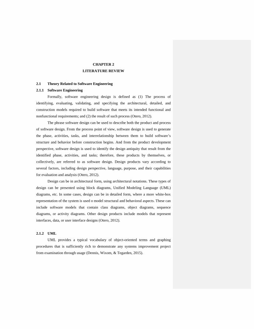
Use cases are represented graphically by a horizontal ellipse with the name of the
use case appearing above, below, or inside the ellipse. A use case represents a single
goal of the system and describes a sequence of activities and user interactions in trying
to accomplish the goal. Use cases are initially defined during the requirements stages of
the life cycle and will be additionally refined throughout the life cycle. (Whitten &
Bentley, 2007).
Figure 2.1 Use Case Diagram Sample
(Source: System Analysis and Design Method - Whitten and Bentley, 2007)
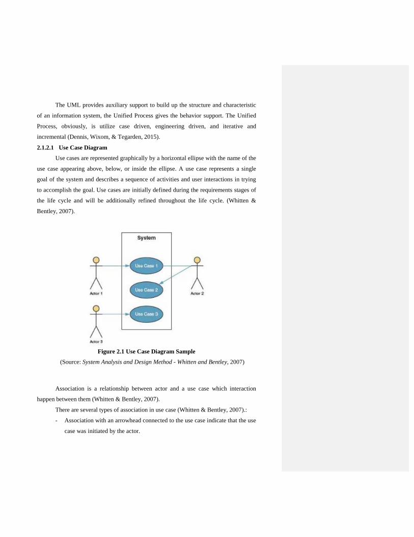
Association is a relationship between actor and a use case which interaction
happen between them (Whitten & Bentley, 2007).
There are several types of association in use case (Whitten & Bentley, 2007).:
- Association with an arrowhead connected to the use case indicate that the use
case was initiated by the actor.
- Association without arrowhead indicates an actor that receive.
Figure 2.2 Association Sample
2.1.2.2 Sequence Diagram
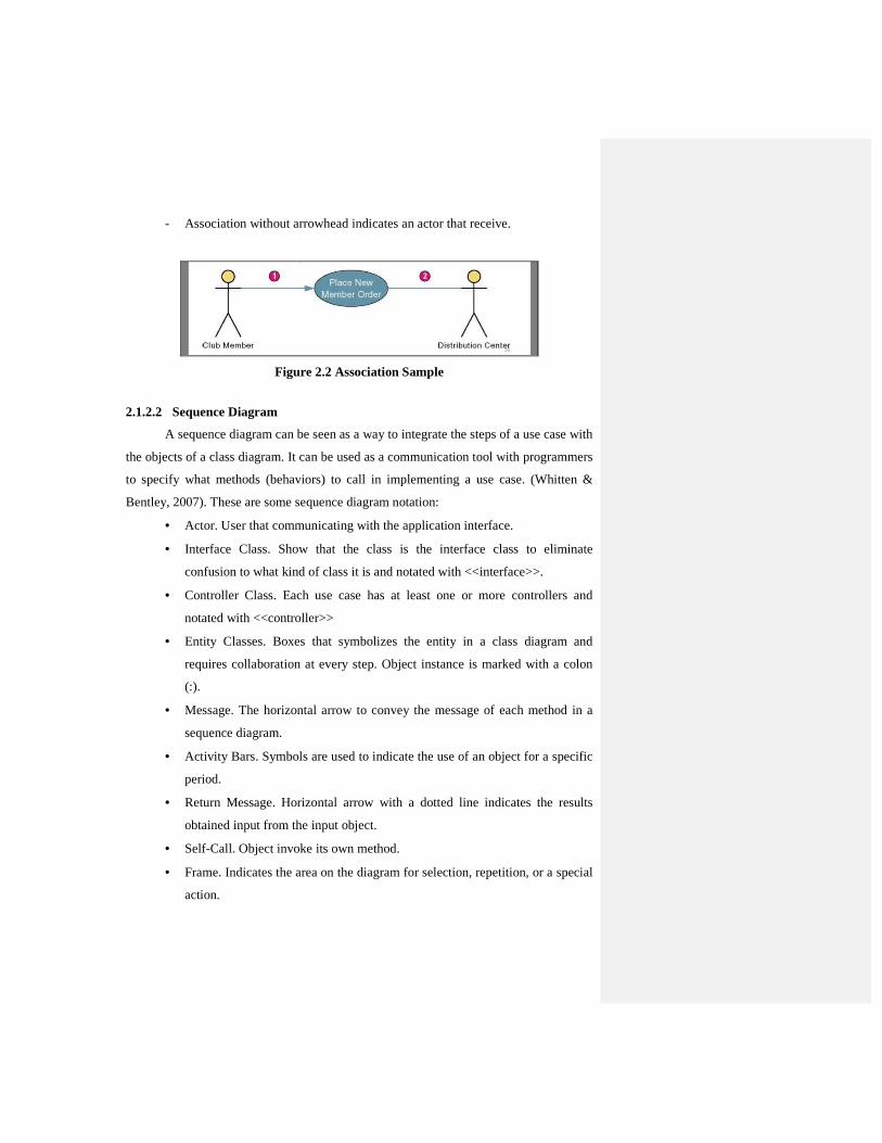
A sequence diagram can be seen as a way to integrate the steps of a use case with
the objects of a class diagram. It can be used as a communication tool with programmers
to specify what methods (behaviors) to call in implementing a use case. (Whitten &
Bentley, 2007). These are some sequence diagram notation:
• Actor. User that communicating with the application interface.
• Interface Class. Show that the class is the interface class to eliminate
confusion to what kind of class it is and notated with <<interface>>.
• Controller Class. Each use case has at least one or more controllers and
notated with <<controller>>
• Entity Classes. Boxes that symbolizes the entity in a class diagram and
requires collaboration at every step. Object instance is marked with a colon
(:).
• Message. The horizontal arrow to convey the message of each method in a
sequence diagram.
• Activity Bars. Symbols are used to indicate the use of an object for a specific
period.
• Return Message. Horizontal arrow with a dotted line indicates the results
obtained input from the input object.
• Self-Call. Object invoke its own method.
• Frame. Indicates the area on the diagram for selection, repetition, or a special
action.
Figure 2.3 Sequence Diagram Sample
(Source: System Analysis and Design Method - Whitten and Bentley, 2007)
2.1.2.3 Class Diagram
Class diagram is a diagram that is used to depict the object static structures and
their associations (Whitten & Bentley, 2007). The following are the types of
relationships that exist in the class diagram (Whitten & Bentley, 2007):
• Association depict the relationship between classes.
• Multiplicity to specify the number of instance of the described element.
• Generalization/Specialization Relationship allows people who create the
class diagram to take advantage of inheritance.
• Aggregation/Composition. Aggregation is used to show that a class can be
aggregated by other class. Composition is used to show that a class has
ownership over other class.
A design class diagram a diagram that depicts classes that correspond to
software components that are used to build the software application. There are some
steps in creating a design class diagram which are (Whitten & Bentley, 2007):
• Add design objects including entity, entity, and control objects to diagram.
• Specify attributes and their types info to design objects.
• Add attributes visibility such as public, protected, or private.
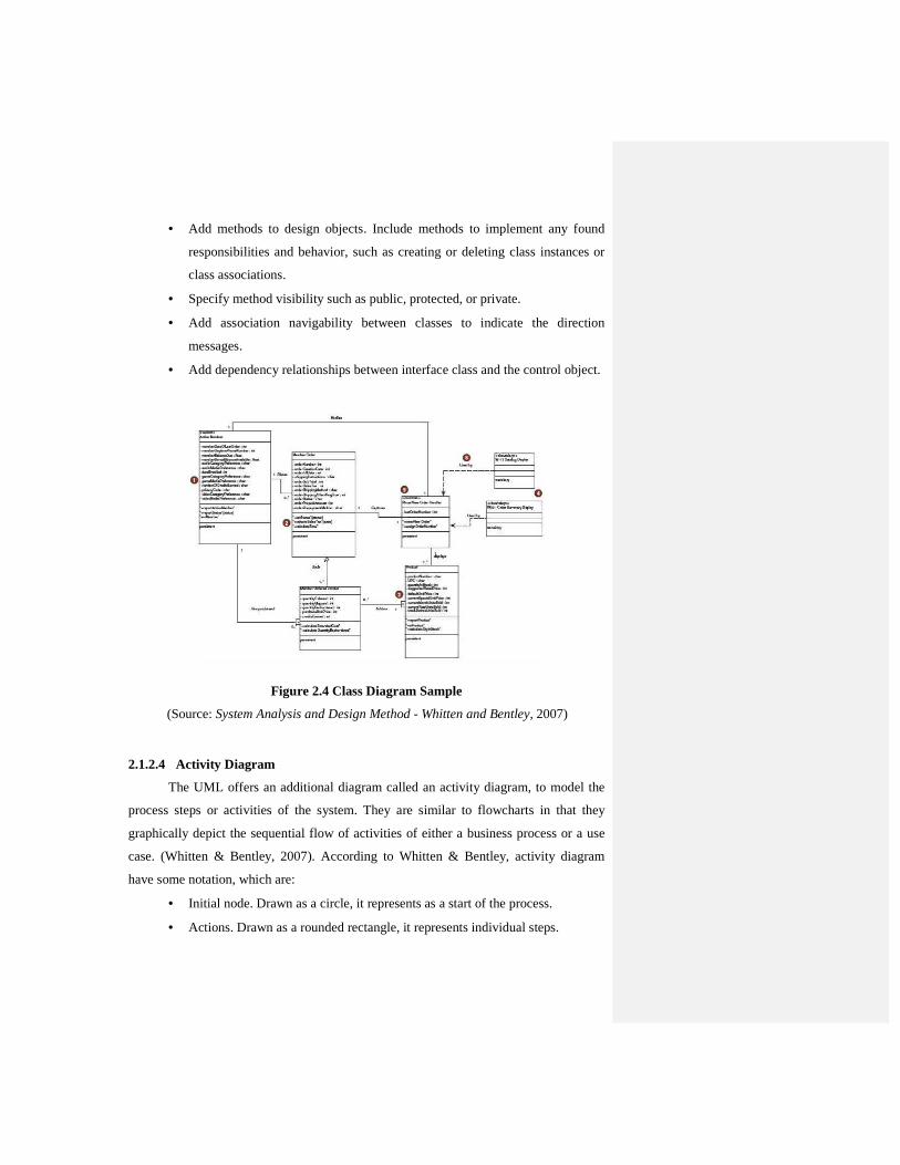
• Add methods to design objects. Include methods to implement any found
responsibilities and behavior, such as creating or deleting class instances or
class associations.
• Specify method visibility such as public, protected, or private.
• Add association navigability between classes to indicate the direction
messages.
• Add dependency relationships between interface class and the control object.
Figure 2.4 Class Diagram Sample
(Source: System Analysis and Design Method - Whitten and Bentley, 2007)
2.1.2.4 Activity Diagram
The UML offers an additional diagram called an activity diagram, to model the
process steps or activities of the system. They are similar to flowcharts in that they
graphically depict the sequential flow of activities of either a business process or a use
case. (Whitten & Bentley, 2007). According to Whitten & Bentley, activity diagram
have some notation, which are:
• Initial node. Drawn as a circle, it represents as a start of the process.
• Actions. Drawn as a rounded rectangle, it represents individual steps.
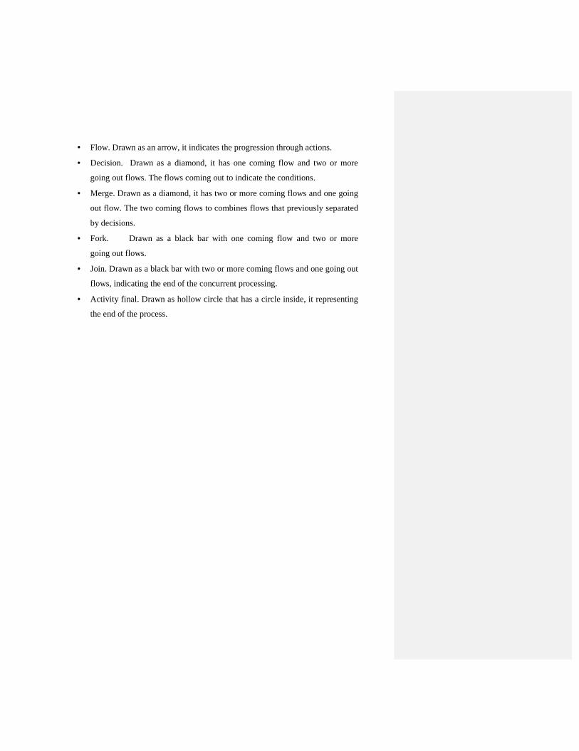
• Flow. Drawn as an arrow, it indicates the progression through actions.
• Decision. Drawn as a diamond, it has one coming flow and two or more
going out flows. The flows coming out to indicate the conditions.
• Merge. Drawn as a diamond, it has two or more coming flows and one going
out flow. The two coming flows to combines flows that previously separated
by decisions.
• Fork. Drawn as a black bar with one coming flow and two or more
going out flows.
• Join. Drawn as a black bar with two or more coming flows and one going out
flows, indicating the end of the concurrent processing.
• Activity final. Drawn as hollow circle that has a circle inside, it representing
the end of the process.
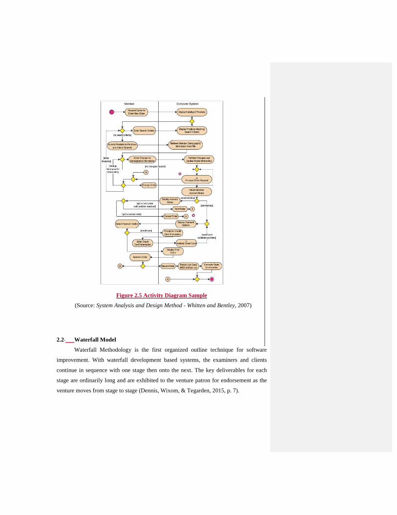
Figure 2.5 Activity Diagram Sample
(Source: System Analysis and Design Method - Whitten and Bentley, 2007)
2.2 Waterfall Model
Waterfall Methodology is the first organized outline technique for software
improvement. With waterfall development based systems, the examiners and clients
continue in sequence with one stage then onto the next. The key deliverables for each
stage are ordinarily long and are exhibited to the venture patron for endorsement as the
venture moves from stage to stage (Dennis, Wixom, & Tegarden, 2015, p. 7).
Figure 2. 8 6 Waterfall Development Methodology
(Source: Systems Analysis and Design: An Object-oriented Approach with UML -
Dennis, Wixom, & Tegarden, 2015 p.7)
2.3 Tools Theory
1. 2.3.1 Android
According to (Lee, 2012), Android is a mobile operating system that is based on a modified version of Linux that is used to develop operating system for touch screen gadget like smartphone or tablet. It was originally developed by a startup of the same name, Android, Inc. Android operating system provides many platform that can be used by developer to create their own application, called open source.
2. 2.3.2 Android Studio
Android Studio is the official integrated development environment (IDE) for the Android platform. The first step to be done in the development of android studio is to configure a computer system to act as the development platform. The steps include the installment of the Android Software Development Kit (SDK) (Smyth, 2015, p.3). There are several system requirements that android application development can be operated (Smyth, 2015, p.3):
� Windows 2003 (32-bit or 54-bit)
� Windows Vista (32-bit or 64-bit)
� Windows 7 (32-bit or 64-bit)
� Windows 8 / Windows 8.1
� Windows 10
� Mac OS X 10.8.5 or later
Formatted: FIGURE, Left, Level 1
Formatted: Indent: Left: 0 cm, Hanging: 1,27 cm,
No bullets or numbering, Tab stops: Not at 1,27 cm
Formatted: Indent: Left: 0 cm, Hanging: 1,27 cm,
No bullets or numbering, Tab stops: Not at 1,27 cm
� Linux systems version 2.11 or later
� GB of Ram minimum (4GB is recommended)
� 1.5 GB available disk space
Figure 2. 7 9 Android Studio Logo
(Source: Android Studio Development Essentials - Smyth, 2015 p.3)
3. 2.3.3 Java Programming Language
Java is a full-featured, universally useful programming language that can be used to create vigorous mission-critical applications. Today, it is mostly used for Web programming, as well as for creating independent applications across platforms on servers, desktops, and cell phones (Liang, 2011, p. 8). Java was utilized to build up the code to speak with and control the robotic rover on Mars. Many organizations that once viewed Java as more buildup than substance are currently utilizing it to make appropriated applications got to by clients and accomplices over the Web (Liang, 2011, p. 8).
4. 2.3.4 Firebase
Firebase provides a real-time database and backend as a service. The service provides application developers an API that allows application data to be synchronized across clients and stored on Firebase's cloud (Farr, 2013). Firebase provides client libraries that enable integration with Android, iOS, JavaScript, Java, Objective-C and Node.js applications. The database is also accessible through a REST API and bindings for several JavaScript frameworks such as AngularJS, React, Ember.js and Backbone.js (Marshall, 2013). Developers using the real-time database can secure their data by using the company's server-side-enforced security rules (Darrow, 2012).
Formatted: FIGURE, Left, Level 1
Formatted: Line spacing: 1,5 lines
Formatted: Indent: Left: 0 cm, Hanging: 1,27 cm,
No bullets or numbering, Tab stops: Not at 1,27 cm
Formatted: Indent: Left: 0 cm, Hanging: 1,27 cm,
No bullets or numbering, Tab stops: Not at 1,27 cm
5. 2.3.5 8 Golden Rule
1.• Strive For Consistency
Predictable groupings of activities ought to be required in
comparative circumstances; indistinguishable wording ought to be utilized as
a part of prompts, menus, and help screens; and reliable shading, format,
upper casing, textual styles, et cetera, ought to be utilized all through.
Exemptions, for example, required affirmation of the erase order or no
resounding of passwords, ought to be understandable and constrained in
number (Shneiderman & Plaisant, 2010).
2.• Cater to Universal Usability
Perceive the necessities of differing clients and plan for pliancy,
encouraging change of substance. Amateur to master contrasts, age ranges,
handicaps, global varieties, and mechanical assorted variety each enhance the
range of necessities that aides plan. Including highlights for tenderfoots, for
example, clarifications, and components for specialists, for example,
alternate routes and speedier pacing, advances the interface outline and
enhances saw quality (Shneiderman & Plaisant, 2010).
3.• Offer Informative Feedback
For each client activity, there ought to be an interface criticism. For
regular and minor activities, the reaction can be unassuming, though for rare
and real activities, the reaction ought to be more significant. Visual
introduction of the objects of intrigue gives an advantageous domain to
demonstrating changes unequivocally (Shneiderman & Plaisant, 2010).
4.• Design dialog to yield closure.
Arrangements of activities ought to be sorted out into bunches with a
starting, center, and end. Useful input toward the finishing of a gathering of
activities gives clients the fulfillment of achievement, a good feeling, a flag
Formatted: Indent: Left: 0 cm, Hanging: 1,27 cm,
No bullets or numbering, Tab stops: Not at 1,27 cm
Formatted: Indent: Left: 1,27 cm, Bulleted + Level: 2
+ Aligned at: 1,9 cm + Indent at: 2,54 cm, Tab
stops: Not at 2,54 cm
Formatted: Indent: Left: 1,9 cm
Formatted: Indent: Left: 1,27 cm, Bulleted + Level: 2
+ Aligned at: 1,9 cm + Indent at: 2,54 cm, Tab
stops: Not at 2,54 cm
Formatted: Indent: Left: 1,9 cm
Formatted: Indent: Left: 1,27 cm, Bulleted + Level: 2
+ Aligned at: 1,9 cm + Indent at: 2,54 cm, Tab
stops: Not at 2,54 cm
Formatted: Indent: Left: 1,9 cm
Formatted: Indent: Left: 1,27 cm, Bulleted + Level: 2
+ Aligned at: 1,9 cm + Indent at: 2,54 cm, Tab
stops: Not at 2,54 cm
Formatted: Indent: Left: 1,9 cm
to drop alternate courses of action from their brains, and a pointer to get
ready for the following gathering of activities. For instance, online business
sites move clients from choosing items to the checkout, finishing with a
reasonable affirmation page that finishes the exchange (Shneiderman &
Plaisant, 2010).
5.• Prevent errors
However much as could reasonably be expected, outline the interface
with the goal that clients can't make genuine mistakes; for instance, dim out
menu things that are not proper and don't permit alphabetic characters in
numeric passage fields. In the event that clients make a mistake, the interface
should offer basic, productive, and particular guidelines for recuperation. For
instance, clients ought not need to retype a whole name-address frame on the
off chance that they enter an invalid postal district but instead ought to be
guided to repair just the defective part. Incorrect activities should leave the
interface state unaltered, or the interface should give guidelines about
reestablishing the state (Shneiderman & Plaisant, 2010).
6.• Permit easy reversal of actions.
However much as could be expected, activities ought to be reversible.
This component mitigates nervousness, since clients realize that blunders can
be fixed, and supports investigation of new alternatives. The units of
reversibility might be a solitary activity, an information section errand, or a
total gathering of activities, for example, passage of a name-address piece
(Shneiderman & Plaisant, 2010).
7.• Support internal locus of control
Experienced clients firmly fancy the feeling that they are accountable
for the interface and that the interface reacts to their activities. They don't
Formatted: Indent: Left: 1,27 cm, Bulleted + Level: 2
+ Aligned at: 1,9 cm + Indent at: 2,54 cm, Tab
stops: Not at 2,54 cm
Formatted: Indent: Left: 1,9 cm
Formatted: Indent: Left: 1,27 cm, Bulleted + Level: 2
+ Aligned at: 1,9 cm + Indent at: 2,54 cm, Tab
stops: Not at 2,54 cm
Formatted: Indent: Left: 1,9 cm
Formatted: Indent: Left: 1,27 cm, Bulleted + Level: 2
+ Aligned at: 1,9 cm + Indent at: 2,54 cm, Tab
stops: Not at 2,54 cm
Formatted: Indent: Left: 1,9 cm
need amazements or changes in recognizable conduct, and they are irritated
by dull information passage arrangements, trouble in acquiring important
data, and powerlessness to deliver their coveted outcome (Shneiderman &
Plaisant, 2010).
8.• Reduce short-term memory load.
People's constrained limit with respect to data preparing in here and
now memory (the general guideline is that individuals can recollect "seven
give or take two lumps" of data) requires that creators keep away from
interfaces in which clients must recall data from one show and afterward
utilize that data on another show. It implies that cellphones ought not require
reentry of telephone numbers, site areas ought to stay obvious, and protracted
structures ought to be compacted to fit a solitary show (Shneiderman &
Plaisant, 2010).
2.3.6 Firebase
Firebase provides a real-time database and backend as a service. The
service provides application developers an API that allows application data to be
synchronized across clients and stored on Firebase's cloud (Farr, 2013). Firebase
provides client libraries that enable integration with Android, iOS, JavaScript,
Java, Objective-C and Node.js applications. The database is also accessible
through a REST API and bindings for several JavaScript frameworks such as
AngularJS, React, Ember.js and Backbone.js (Marshall, 2013). Developers using
the real-time database can secure their data by using the company's server-side-
enforced security rules (Darrow, 2012).
2.4 Social Media
According to (Kaplan & Haenlein, 2010), Social media can be classified
using social presence/media richness and self-presentation / self-disclosure.
Combining both dimensions leads to a classification of Social Media which we
have visualized in Figure 2.8.
Formatted: Indent: Left: 1,27 cm, Bulleted + Level: 2
+ Aligned at: 1,9 cm + Indent at: 2,54 cm, Tab
stops: Not at 2,54 cm
Formatted: Indent: Left: 1,9 cm
Formatted: Space After: 0 pt
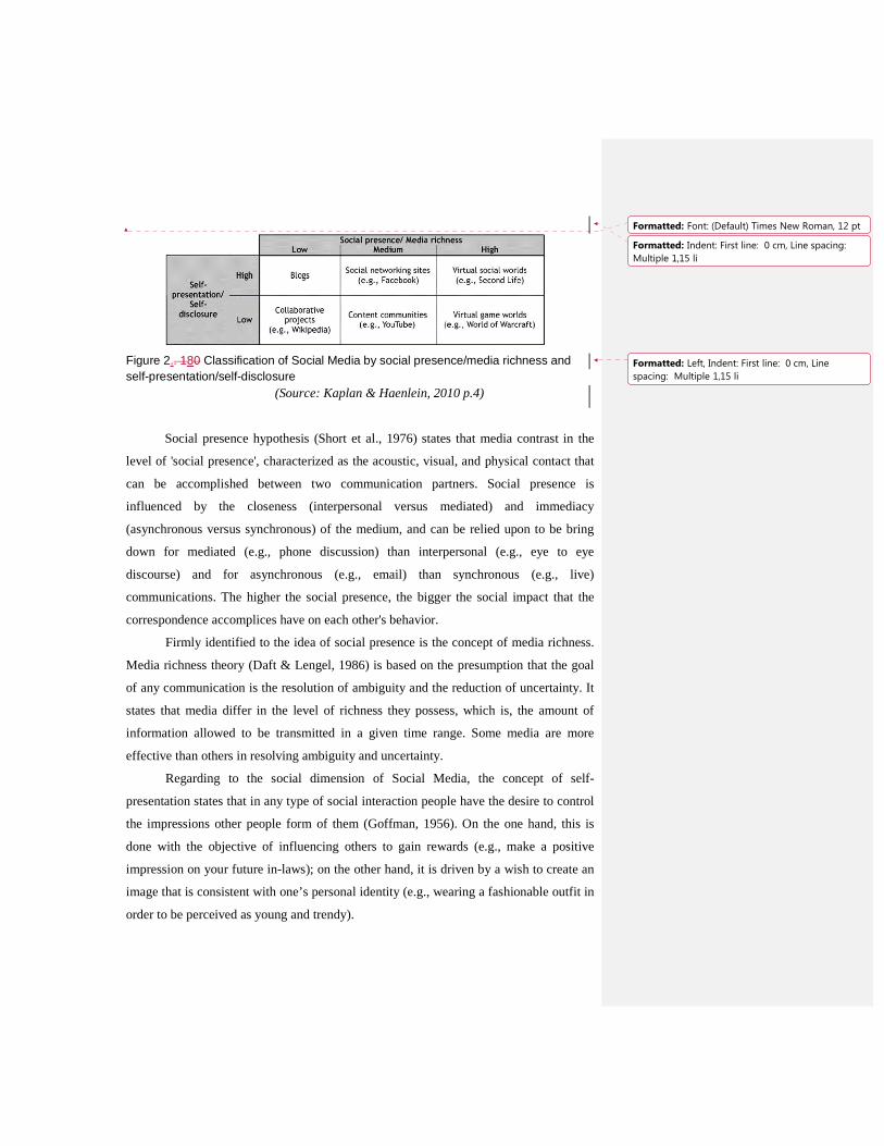
Figure 2.. 180 Classification of Social Media by social presence/media richness and self-presentation/self-disclosure
(Source: Kaplan & Haenlein, 2010 p.4)
Social presence hypothesis (Short et al., 1976) states that media contrast in the
level of 'social presence', characterized as the acoustic, visual, and physical contact that
can be accomplished between two communication partners. Social presence is
influenced by the closeness (interpersonal versus mediated) and immediacy
(asynchronous versus synchronous) of the medium, and can be relied upon to be bring
down for mediated (e.g., phone discussion) than interpersonal (e.g., eye to eye
discourse) and for asynchronous (e.g., email) than synchronous (e.g., live)
communications. The higher the social presence, the bigger the social impact that the
correspondence accomplices have on each other's behavior.
Firmly identified to the idea of social presence is the concept of media richness.
Media richness theory (Daft & Lengel, 1986) is based on the presumption that the goal
of any communication is the resolution of ambiguity and the reduction of uncertainty. It
states that media differ in the level of richness they possess, which is, the amount of
information allowed to be transmitted in a given time range. Some media are more
effective than others in resolving ambiguity and uncertainty.
Regarding to the social dimension of Social Media, the concept of self-
presentation states that in any type of social interaction people have the desire to control
the impressions other people form of them (Goffman, 1956). On the one hand, this is
done with the objective of influencing others to gain rewards (e.g., make a positive
impression on your future in-laws); on the other hand, it is driven by a wish to create an
image that is consistent with one’s personal identity (e.g., wearing a fashionable outfit in
order to be perceived as young and trendy).
Formatted: Font: (Default) Times New Roman, 12 pt
Formatted: Indent: First line: 0 cm, Line spacing:
Multiple 1,15 li
Formatted: Left, Indent: First line: 0 cm, Line
spacing: Multiple 1,15 li
The main reason why people decide to create a personal webpage is, for
example, the urge to present themselves in cyberspace (Schau & Gilly, 2003). Usually,
such a presentation is done through self-disclosure; that is, the conscious or unconscious
revelation of personal information (e.g., thoughts, feelings, likes, dislikes) that is
consistent with the image one would like to give. Self-disclosure is a critical step in the
development of close relationships (e.g., during dating) but can also occur between
complete strangers; for example, when speaking about private matters with the person
seated next to you on an bus stop.
Each social media represents different amount of social presence and media
richness as well as amount of self-presentation and self-disclosure. Example is a blog
presents high self-presentation and self-disclosure compared to collaborative projects
where bloggers try to deliver an image of their personal to be acknowledge by other
users compared to the contributors of collaborative projects which are anonymous.
While comparing blogs and social networking sites that has different amount of social
presence and media richness, blogs shows more text in the layout. Social networking
sites are richer in media richness which allows user to upload contents such as text,
pictures, videos, and files. These contents are also called as User-generated content.
User Generated Content (UGC) can be seen as the sum of all ways in which people
make use of Social Media. The term UGC, is usually applied to describe the various
forms of media content that are publicly available and created by end-users.
1. 2.4.1 Social Networking Sites
As stated by (Kaplan & Haenlein, 2010), Social networking sites are applications
that enable users to connect by creating personal information profiles, inviting friends
and colleagues to have access to those profiles, and sending e-mails and instant
messages between each other. These personal profiles can include any type of
information, including photos, video, audio files, and blogs. Therefore, a social media
can be categorized as social networking sites when it fulfils these two criteria:
• Medium social presence/media richness
• High self-presentation/self-disclosure
•
Formatted: Indent: Left: 0 cm, Hanging: 1,27 cm,
No bullets or numbering, Tab stops: Not at 1,27 cm
Formatted: Left, Indent: Left: 0 cm
Formatted: Indent: Left: 1,27 cm, Space After: 0 pt,
Bulleted + Level: 1 + Aligned at: 1,42 cm + Indent
at: 2,06 cm
Formatted: Indent: Left: 1,9 cm, Space After: 0 pt,
No bullets or numbering
2.5 Gamification
Gamification manages applying gaming mechanics to non-gaming circumstances.
Gamification has been utilized to reconstruct classrooms and to support learning, and,
just like games, it too has been utilized to expand client and worker engagement
(Dennis, Wixom, & Tegarden, 2015, p. 400).
In both practicing games and gamification, the key to achievement manages rousing the
client as well as representative to stay engaged in with the business procedure. Despite
the fact that conventional inspiration approaches have attempted to encourage
representatives before, because of the way of the changing sorts of work performed, they
no longer capacity in a productive or viable way (Dennis, Wixom, & Tegarden, 2015, p.
401).
2.6 Hoax
Hoax is an intentionally manufactured lie made to take on the appearance of reality. It is
recognizable from mistakes in perception or judgment, gossipy tidbits, urban legends,
pseudo sciences, and April Dolts' Day occasions that are passed along in compliance
with common decency by believers or as jokes (Brunvand, 2002).
2. 2.6.1 Types of Hoax
Hoaxes differ generally in their processes of creation, propagation, and entrenchment
over time. For example:
1.• Academic hoaxes
2.• Religious hoaxes
3.• Hoaxes perpetrated on occasions when their initiation is considered socially
appropriate, such as April Fools' Day
4.• Criminal Hoaxing. (Brunvand, 2002)
5.• Internet hoaxes became more common after the start of social media. Some
websites have been used to hoax millions of people on the Web. (Phillip,
2014)
Formatted: Left, Indent: Left: 0 cm, First line: 0 cm
Formatted: Font: (Default) Times New Roman, 12 pt
Formatted: Normal, Line spacing: 1,5 lines
Formatted: Left, Indent: Left: 0 cm, First line: 0 cm
Formatted: Font: (Default) Times New Roman, 12 pt
Formatted: Indent: Left: 1,27 cm, Space After: 0 pt,
Bulleted + Level: 1 + Aligned at: 3,17 cm + Indent
at: 3,81 cm, Tab stops: Not at 1,27 cm
2.7 State of Arts
1. QUESTDONE APPLICATION WITH SOCIAL NETWORKING FEATURES AS
THE ACTUAL WORLD INTERACTION MEDIA ON ANDROID
SMARTPHONE (2012)
• Social networking is a set of people that form a gathering in order to assemble
and share a ton of information, similar to how to cook, brandish, occupation,
business, and different themes. For a few clients, social networking can be
applied as search engine and an advancement media that is more financially
savvy and it can be seen by many individuals in brief time (Sutoyo, Yoshep,
Susanto, & Kurniadinata, 2012).
• More or less, half social networking that exists as of now just depends on
cooperation amongst client and virtual world interface. Because of that, the
client can't specifically associate with nature and mingle altogether. This sort of
association additionally happens on publicizing media, where ads just conveys
data however can't make coordinate cooperation that includes client and the
offered items (Sutoyo et al., 2012).
• QuestDone is a search-and-discovery service mobile application which gives
indexed lists to its clients. It is similar to Foursquare, Clingle, Loopt,
Brightkite, Wallit, etc. The application gives customized suggestions of spots to
go to close to a client's present area in light of clients' "past browsing history,
buys, or registration history. It is similar to Foursquare, Clingle, and Wallit.
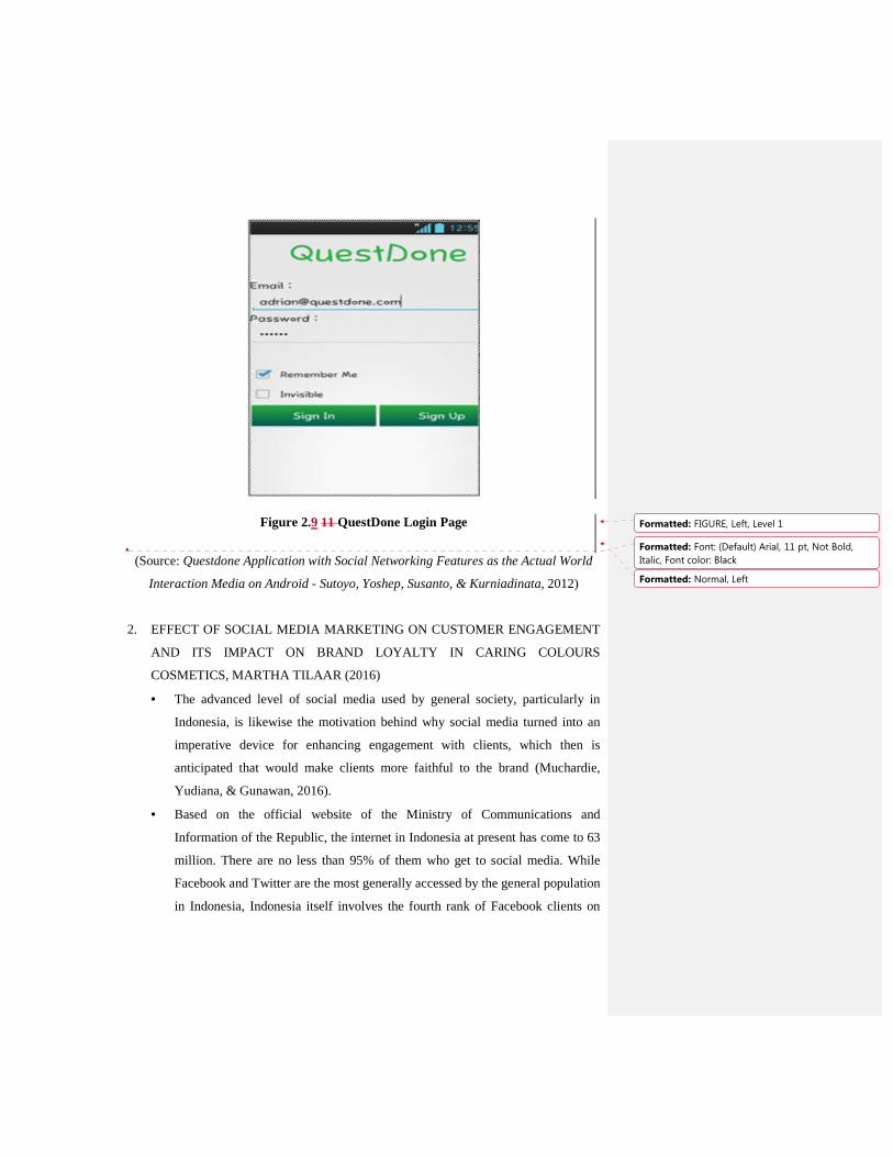
Figure 2.9 11 QuestDone Login Page
(Source: Questdone Application with Social Networking Features as the Actual World
Interaction Media on Android - Sutoyo, Yoshep, Susanto, & Kurniadinata, 2012)
2. EFFECT OF SOCIAL MEDIA MARKETING ON CUSTOMER ENGAGEMENT
AND ITS IMPACT ON BRAND LOYALTY IN CARING COLOURS
COSMETICS, MARTHA TILAAR (2016)
• The advanced level of social media used by general society, particularly in
Indonesia, is likewise the motivation behind why social media turned into an
imperative device for enhancing engagement with clients, which then is
anticipated that would make clients more faithful to the brand (Muchardie,
Yudiana, & Gunawan, 2016).
• Based on the official website of the Ministry of Communications and
Information of the Republic, the internet in Indonesia at present has come to 63
million. There are no less than 95% of them who get to social media. While
Facebook and Twitter are the most generally accessed by the general population
in Indonesia, Indonesia itself involves the fourth rank of Facebook clients on
Formatted: FIGURE, Left, Level 1
Formatted: Font: (Default) Arial, 11 pt, Not Bold,
Italic, Font color: Black
Formatted: Normal, Left
the planet after the USA, Brazil, and India, with around 65 million active and
dynamic Facebook clients brand (Muchardie et al., 2016).
3.
4.3. THE IMPACT OF SOCIAL MEDIA ON STUDENT LEARNING CASE STUDY:
SMA YAPITA SURABAYA (2016)
• The growing learning environment is enabling students to learn at whatever
time and anyplace. Those social media or social networking are ending up
noticeably more popular and generally spread. According to The Wall Street
Journal, Facebook users in Indonesia has reached 69 million people and keep
escalating day by day (Isnaini & Rakhmawati, 2016).
• One of negative parts of utilizing online networking advancements is limit the
dynamic support of the learner. Actually, such advanced technologies are
created with the goal that they can work for any learner, despite the inspiration
or the capacity of the specific learner (Isnaini & Rakhmawati, 2016).
5.4. RELATIONSHIP BETWEEN SOCIAL MEDIA FOR SOCIAL MARKETING IN
FAMILY PLANNING (2013)
• The advancement of Information Technology (IT) generally and the internet
has totally give impact to human behavior to communicate and interact to each
other. Limits of space and time is not an obstacle in conveying and interacting,
it is more conceivable through the rising wonder of Smartphone innovation to
give internet access (Ardiansyah, 2013).
• This research journal is intended to see whether the source credibility altogether
impact attitude, knowing whether brand mindfulness altogether impact attitude,
knowing whether brand engagement altogether impact attitude and knowing
whether word of mouth essentially impact attitude (Ardiansyah, 2013).
6.5. ELECTRONIC WORD OF MOUTH (E-WOM) FOURSQUARE: THE NEW
SOCIAL MEDIA (2013)
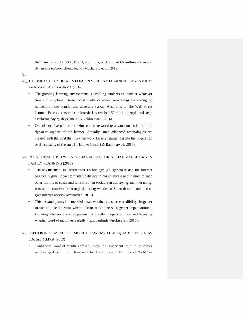
• Traditional word-of-mouth (offline) plays an important role in customer
purchasing decision. But along with the development of the Internet, WoM has
now grown to be Electronic word-of-mouth (e-wom). The motive of e-WoM
itself is different from the motives of WoM as it is influenced by the dynamic
social needs of the community, the development of information technology, the
development of new media, and others (Hutomo, 2013).
Figure 2. 1210 Foursquare Users
(Source: Electronic Word of Mouth (E-Wom) Foursquare: The New Social Media -
Hutomo, 2012)
7.6. ‘HOAX ANALYZER’ WINS AT MICROSOFT SOFTWARE DEVELOPMENT
CONTEST (2017)
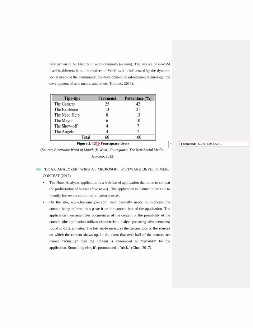
• The Hoax Analyzer application is a web-based application that aims to combat
the proliferation of hoaxes (fake news). This application is claimed to be able to
identify hoaxes on certain information sources.
• On the site, www.hoaxanalyzer.com, user basically needs to duplicate the
content being referred to a paste it on the content box of the application. The
application then assembles occurrences of the content or the possibility of the
content (the application utilizes characteristic dialect preparing advancements)
found in different sites. The last stride measures the destinations or the sources
on which the content shows up. In the event that over half of the sources are
named "actuality" then the content is announced as "certainty" by the
application. Something else, it's pronounced a "trick." (Chua, 2017).
Formatted: FIGURE, Left, Level 1
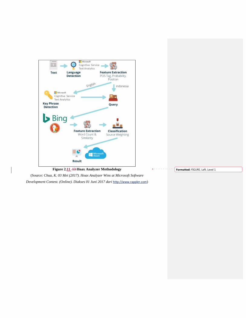
Figure 2.11 13 Hoax Analyzer Methodology
(Source: Chua, K. 03 Mei (2017). Hoax Analyzer Wins at Microsoft Software
Development Contest. (Online). Diakses 01 Juni 2017 dari http://www.rappler.com)
Formatted: FIGURE, Left, Level 1
Related Documents