9 CHAPTER 2 LITERATURE REVIEW 2.1 HIGH STRENGTH LOW ALLOY STEEL High Strength Low Alloy (HSLA) steel is a type of steel alloy that provides better mechanical properties or greater resistance to corrosion than carbon steel. HSLA steels vary from other steels in that they are not made to meet a specific chemical composition, but rather to specific mechanical properties. They have carbon content between 0.05–0.5% to retain formability and weldability. Other alloying elements include up to 2.0% manganese and small quantities of copper, nickel, niobium, nitrogen, vanadium, chromium, molybdenum, titanium, calcium, rare earth elements, or zirconium (Huppmann and Mhirschragel 1976, Peter Lee and Howard Kuhn 1987). Copper, titanium, vanadium, and niobium are added for strengthening purposes (Peter Lee and Howard Kuhn 1987). These elements are intended to alter the microstructure of carbon steels, which is usually a ferrite-pearlite aggregate, to produce a very fine dispersion of alloy carbides in an almost pure ferrite matrix. This eliminates the toughness-reducing effect of a pearlitic volume fraction, yet maintains and increases the material's strength by refining the grain size, which in the case of ferrite increases yield strength by 50% for every halving of the mean grain diameter. Precipitation strengthening plays a minor role, too. Their yield strengths can be anywhere between 250– 590 MPa (36,000–86,000 psi). Due to their higher strength and toughness HSLA steels usually require 25 to 30% more power as compared to carbon steels (Peter Lee and Howard Kuhn 1987).

Welcome message from author
This document is posted to help you gain knowledge. Please leave a comment to let me know what you think about it! Share it to your friends and learn new things together.
Transcript
9
CHAPTER 2
LITERATURE REVIEW
2.1 HIGH STRENGTH LOW ALLOY STEEL
High Strength Low Alloy (HSLA) steel is a type of steel alloy that
provides better mechanical properties or greater resistance to corrosion than
carbon steel. HSLA steels vary from other steels in that they are not made to
meet a specific chemical composition, but rather to specific mechanical
properties. They have carbon content between 0.05–0.5% to retain formability
and weldability. Other alloying elements include up to 2.0% manganese and
small quantities of copper, nickel, niobium, nitrogen, vanadium, chromium,
molybdenum, titanium, calcium, rare earth elements, or zirconium
(Huppmann and Mhirschragel 1976, Peter Lee and Howard Kuhn 1987).
Copper, titanium, vanadium, and niobium are added for strengthening
purposes (Peter Lee and Howard Kuhn 1987). These elements are intended to
alter the microstructure of carbon steels, which is usually a ferrite-pearlite
aggregate, to produce a very fine dispersion of alloy carbides in an almost
pure ferrite matrix. This eliminates the toughness-reducing effect of a pearlitic
volume fraction, yet maintains and increases the material's strength by
refining the grain size, which in the case of ferrite increases yield strength by
50% for every halving of the mean grain diameter. Precipitation strengthening
plays a minor role, too. Their yield strengths can be anywhere between 250–
590 MPa (36,000–86,000 psi). Due to their higher strength and toughness
HSLA steels usually require 25 to 30% more power as compared to carbon
steels (Peter Lee and Howard Kuhn 1987).
10
Research on the development of new high-strength, high-toughness
and corrosion-resistant steels with outstanding fracture toughness and tensile
strength combination for landing gear materials has been a subject of intense
interest in the recent times. Improved Ni-Co, low carbon steels (most notably
Aermet100 and AF1410), have excellent combinations of properties and are
developed to the point where they are now being specified as replacements for
the standard landing gear steels 300M and 4140 (Wisker and Jones 1974).
These improved steels are used for landing gear on carrier-based
aircraft because they exhibit excellent damage tolerance and environmental
resistance. The steels can also find application as attach fittings, horizontal
stabilizer spindles, arresting-hook shanks, and catapult hooks. Other
aerospace applications under consideration include rotorcraft actuators and
masts, gas turbine engine shafts, and rocket motor casings. Non-aerospace
applications include ordnance, armor, high-strength fasteners, pump splines,
and automotive drive shafts (Huppmann and Mhirschragel 1976, Huppmann
1977).
The improved combination of strength, damage tolerance, and
stress corrosion cracking resistance provides significant benefits for
applications under severe service conditions, such as the naval aircraft
environment. An additional benefit includes fatigue strength superior to 300M
steel. These materials have good weldability because of low carbon content.
Testing has shown that UHSS (Ultra High Strength Steel) can be welded,
without preheat, with joint efficiencies approaching 100 percent.
It appears that the strength of these new steels cannot increase to
higher levels without corresponding decreases in ductility and toughness
(Kotschy et al 1976). However, increased strength can be achieved while
11
keeping toughness at levels acceptable for many applications. Such a balance
of properties may be acceptable for landing gear for civil aircraft.
It has been observed that, as strength increases, toughness
decreases, therefore toughness of ultra high strength steel is an important
consideration. These super alloys meet these requirements offering excellent
fracture toughness and strength. The ultra high strength of this steel is
attributed to the presence and distribution of the fine second phase particles
such as (MoCr) 2C, (MoFe) xC, (Fe,Ni,Co) 3C (Antes 1971). Furthermore,
heat treatment, grain size, precipitates; dislocation structures size-shape and
distribution of inclusions and compositions of matrix can generate variations
on material properties. All of these parameters are very important in order to
enhance the toughness of steel. Large second phase particles (carbides) and
less distance between them can produce detrimental effect in toughness and
tensile strength of the material. These microstructural characteristics can
enhance the crack tip blunting and improve the resistance to fatigue crack
growth (Antes 1974).
Copper, silicon, nickel, chromium, and phosphorus are added to
increase corrosion resistance. Zirconium, calcium, and rare earth elements are
added for sulfide-inclusion shape control which increases formability. These
are needed because most HSLA steels have directionally sensitive properties.
Formability and impact strength can vary significantly when tested
longitudinally and transversely to the grain. Bends that are parallel to the
longitudinal grain are more likely to crack around the outer edge because they
experience tensile loads. This directional characteristic is substantially
reduced in HSLA steels that have been treated for sulfide shape control (Peter
Lee and Howard Kuhn 1987).
12
They are used in cars, trucks, cranes, bridges, and other structures
that are designed to handle large amounts of stress or need a good strength-to-
weight ratio (Peter Lee and Howard Kuhn 1987).
2.2 POWDER METALLURGY
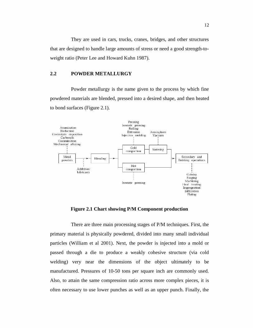
Powder metallurgy is the name given to the process by which fine
powdered materials are blended, pressed into a desired shape, and then heated
to bond surfaces (Figure 2.1).
Figure 2.1 Chart showing P/M Component production
There are three main processing stages of P/M techniques. First, the
primary material is physically powdered, divided into many small individual
particles (William et al 2001). Next, the powder is injected into a mold or
passed through a die to produce a weakly cohesive structure (via cold
welding) very near the dimensions of the object ultimately to be
manufactured. Pressures of 10-50 tons per square inch are commonly used.
Also, to attain the same compression ratio across more complex pieces, it is
often necessary to use lower punches as well as an upper punch. Finally, the
13
end part is formed by applying pressure, high temperature, long setting times
(during which self-welding occurs), or any combination thereof.
Powder metallurgy is the process of blending fine powdered
materials, pressing them into a desired shape or form (compacting), and then
heating the compressed material in a controlled atmosphere to bond the
material (sintering). The powder metallurgy process generally consists of four
basic steps: (1) powder manufacture, (2) powder blending,(3) compacting,
(4) sintering. Compacting is generally performed at room temperature, and the
elevated-temperature process of sintering is usually conducted at atmospheric
pressure. Optional secondary processing often follows to obtain special
properties or enhanced precision. Two main techniques used to form and
consolidate the powder are sintering and metal injection molding. Recent
developments have made it possible to use rapid manufacturing techniques
which use the metal powder for the products. Because with this technique the
powder is melted and not sintered, better mechanical strength can be
accomplished.
2.2.1 Production Aspects of HSLA Steel Alloy
Production aspects of HSLA steel involves the following steps
Powder Production
Compaction
Sintering
Secondary and other finishing operations
14
2.2.1.1 Powder production
The raw material for P/M components is the powder. These
powders are engineered materials in the sense they are manufactured to
precise specifications to facilitate subsequent processing (Jena et al 2010).
The powders used in P/M can be pure elements, elemental blends or pre-
alloyed powders. Several production methods are available for making
powders like atomization, reduction of compounds, electrolysis, etc.
Most metals are fabricated by atomization techniques. The use of
molten alloy and high velocity water or gas jet provides a major amount of
powder (Misra et al 2008). The gas and centrifugal techniques produce
spherical powder, while water atomization gives an irregular shape. Particle
size is controlled by the energy delivery per unit volume of molten metal. The
greater the energy delivers to the metal stream the finer the resulting particle
size.
The mechanical method produces coarse, irregular or angular
powders via machining, milling, crushing or impacting routes. Due to
increased concerns of energy efficiency, the mechanical fabrication
approaches are not attractive. Probably, the one major exception in the
mechanical alloying approach to the formation of alloy dispersion
strengthened alloys relieves on repeated milling fracture welding events on a
macroscopic scale (Brown 1971). Any fusible material can be atomized.
Several techniques have been developed which permit large production rates
of powdered particles, often with considerable control over the size ranges of
the final grain population. Powders may be prepared by grinding, chemical
reactions, or electrolytic deposition. Powders of the elements titanium,
vanadium, thorium, niobium, tantalum, calcium, and uranium have been
15
produced by high-temperature reduction of the corresponding nitrides and
carbides. Iron, nickel, uranium, and beryllium submicrometre powders are
obtained by reducing metallic oxalates and formates. Exceedingly fine
particles also have been prepared by directing a stream of molten metal
through a high-temperature plasma jet or flame, simultaneously atomizing and
comminuting the material. On earth various chemical- and flame-associated
powdering processes are adopted in part to prevent serious degradation of
particle surfaces by atmospheric oxygen.
2.2.1.1(a) Apparent Density
The mass of the unit volume of powder in the loose or unpacked
condition, usually expressed in g/cc. For powder metallurgy powders, it is
often 50% of the theoretical density for the materials.
Apparent density is not only of importance in P/M but also in other
fields such as point, pigments, chemical reagents and pyrotechnical
applications. The apparent density of a powder, sometimes called packing
density or loading weight, is defined as the mass per unit volume of loose or
unpacked powder. Thus it includes internal pores but excludes external pores.
It is governed by chemical composition, particle shape, size distribution.
2.2.1.1(b) Tap Density
The density of powder obtained when it is vibrated for a prolonged
period. The tap density represents the highest packing density possible for a
powder without the application of pressure.
Tap Density is always higher than the free flow apparent Density.
Tap density is the apparent density of the powder after it has been
16
mechanically shaken down or tapped until the level of the powder no longer
falls .it appears to be widely used for storage, packing or transport of
commercial powder and also as a control test on mixed powders .since
tapping or vibration tends to segregate fines, different sized particles and
materials with different specific gravities, it interferes with the uniform
packing of particles.
2.2.1.1(c) Relative Density
It is a dimensionless quantity, as it is the ratio of either densities or
weights
R =
where, R is relative density, - Actual is the density of the substance being
measured and - theoretical is the density of the reference.
Relative density can be calculated directly by measuring the density
of a sample and dividing it by the (known) density of the reference substance.
The density of the sample is simply its mass divided by its volume. Although
mass is easy to measure, the volume of an irregularly shaped sample can be
more difficult to ascertain.
Relative density or specific gravity is the ratio of the density (mass
of a unit volume) of a substance to the density of a given reference material.
Specific gravity usually means relative density with respect to water. The
term "relative density" is often preferred in modern scientific usage.
If a substance's relative density is less than one then it is less dense
than the reference; if greater than 1 then it is denser than the reference. If the
17
relative density is exactly 1 then the densities are equal; that is, equal volumes
of the two substances have the same mass. If the reference material is water
then a substance with a relative density (or specific gravity) less than 1 will
float in water. For example, an ice cube, with a relative density of about 0.91,
will float. A substance with a relative density greater than 1 will sink.
Temperature and pressure must be specified for both the sample
and the reference. Pressure is nearly always 1atm equal to 101.325 kPa.
Where it is not, it is more usual to specify the density directly. Temperatures
for both sample and reference vary from industry to industry. In British
brewing practice the specific gravity as specified above is multiplied by 1000.
Specific gravity is commonly used in industry as a simple means of obtaining
information about the concentration of solutions of various materials such as
brines, sugar solutions (syrups, juices, honeys, brewers wort, must, etc.) and
acids.
2.2.1.1(d) Green Density
Green Density is density of Green compact. The weight per unit
volume of an un sintered compact
In general, green density has been found to
(i) Increase of compaction pressure
(ii) The increase of particle size or apparent density
(iii) The decrease of particle hardness and
(iv) The decrease of compacting speed. Improvements in green
density may also be affected by employing smooth and
18
regularly shaped annealed particles with high particle
densities.
In case of regular shaped compacts eg. Cube, cylinder tetragon, bar,
etc, the green density is readily determined from their weight and dimensions
.however, for compacts with irregular contours it measured by weighting in
air and water. In the latter case impregnation with oil or other lubricant is the
usual procedure transparent lacquer coating may also be employed but it is
not widely used.
2.2.1.1(e) Sintered Density
The methods used for determination of sintered density are similar
to those which have already been described for the determination of green
density. The property facilitates rendering of information or porosity of the
finished product. The mechanical properties, in general, increase with the
decrease in porosity of the sintered compact. It is expressed in g/cc.
2.2.1.1(f) Flow Rate
The time required for a powder sample a standard weight to flow
through an orifice in a standard instrument according to a specified procedure.
A related test used to determine the ease of flow of powders is the
flow time, measure the time taken for a known weight of powder sample to all
through a specially designed funnel called the Hall funnel.
The flow rate is a very important characteristic of powder which
measures the ability of a powder to be transferred .it is defined as the rate at
which a metal powder will flow under gravity from a container through an
19
orifice both having the specific shape without bridge formation for obtaining
a rapid rate of production, consistent compacts and economy.
It is the amount of a substance which passes through a specified
surface per unit time. The flow rate can be based on mass (mass flow rate),
volume (volume flow rate) or mole (mole flow rate)
2.2.1.1(g) Aspect Ratio
The aspect ratio (i.e. height to diameter ratio) is the density
variations created by friction effects between the powder feedstock and the
tooling mean that, even with double-ended compaction, aspect ratio should be
limited to no more than 3:1.
2.2.1.1(h) Porosity
The amount of pores (voids) expressed as a percentage of the total
volume of the powder metallurgy part.
The presence of porosity has a much greater influence on the
elongation, and impact and fatigue strength and a rapid increase in these
values is obtained with the density approaching the theoretical. Porosity acts
as stress raiser and sintered component does not indicate truly elastic
behavior, rather it appears to function in a similar manner as graphite in cast
iron.
2.2.1.2 Compaction
Compaction of powder mixtures is generally carried out using dies
to close tolerances. Dies are made typically from die steels or cemented
20
carbides. Equipment used for compaction includes mechanical or hydraulic
presses.
The main purpose of compaction is to
Consolidate the powder into desired shape
Impart desired level and type of porosity
Produce green compacts with sufficient strength to withstand
further handling operations
Die compaction represents the most widely used method and is
considered as the conventional technique. These involve rigid dies and special
mechanical or hydraulic pressures (Hirschhorn and Bargainnier 1970).
Density of up to 90% of full solid density can be achieved. Following the
compaction cycle the duration may be of order of just a few seconds for very
small parts. Mechanical process is now available in capacity up to 20 MN
force or several thousand tons force for hydraulic press: these capacities are
determined by the size of part that can be pressed to a given green density.
Powder compaction is the process of compacting metal powder in a die
through the application of high pressures. Typically the tools are held in the
vertical orientation with the punch tool forming the bottom of the cavity. The
powder is then compacted into a shape and then ejected from the die cavity.
In a number of these applications the parts may require very little additional
work for their intended use; making them very cost efficient.
There are four major classes of tool styles: single-action
compaction, used for thin, flat components; opposed double-action with two
punch motions, which accommodates thicker components; double-action with
floating die; and double action withdrawal die. Double action classes give
21
much better density distribution than single action. Tooling must be designed
so that it will withstand the extreme pressure without deforming or bending.
Tools must be made from materials that are polished and wear-resistant.
Better workpiece materials can be obtained by repressing and re-sintering.
2.2.1.3 Sintering
In this process, heating of the 'green' compact is carried out in a
protective atmosphere within a furnace at a temperature below the melting
point of the base metal. These temperatures are generally 75% of the absolute
melting temperature. Sintering thus will be decreased in the number of
process, the pore shape will tend to become smooth and the grain growths will
take place. It is possible that some melting or liquid phase sintering of other
powder additives may take place during sintering.
‘Sintering’ is a method used to create objects from powders. It is
based on atomic diffusion. Diffusion occurs in any material above absolute
zero, but it occurs much faster at higher temperatures. In most sintering
processes, the powdered material is held in a mold and then heated to a
temperature below the melting point. The atoms in the powder particles
diffuse across the boundaries of the particles, fusing the particles together and
creating one solid piece. Because the sintering temperature does not have to
reach the melting point of the material, sintering is often chosen as the
shaping process for materials with extremely high melting points such as
tungsten and molybdenum. Sintering is traditionally used for manufacturing
ceramic objects but finds applications in almost all fields of industry. The
study of sintering and of powder-related processes is known as powder
metallurgy. A simple, intuitive example of sintering can be observed when ice
cubes in a glass of water adhere to each other.
22
The process of sintering is generally the result of atomic motion
stimulated by the high temperatures. The initial strains, surface area and
curvatures existing in a pressed powder, compact drive the atomic motions
responsible for sintering (Kahlow 1971). Several different patterns of atomic
motion can contribute to the effect including evaporation and condensation,
volume diffusion, grain boundary and surface diffusion, and plastic flow. In
most cases, the sintering Kinetics is determined by several parameters
including pressed density, material, particle size, sintering atmosphere,
temperature and even the degree of sintering. As material transport takes
place, the geometric progression can be divided into a number of stages
representing the driving forces.
These are
Initial bonding among particles
Neck growth
Pore channel closure
Pore rounding
Pore shrinkage
Pore coarsening
To enhance the overall densification process, it is common to
impose an external force through pressure or to provide a high active kinetic
path through the addition of a second phase. Hot pressing techniques use
super imposed temperature and pressure effects to give rapid, controlled
densification. The form of hot pressing can be manifested as either uniaxial or
hydrostatic forces (Kaufman and Mocarski 1971). In recent, years hot forging
23
in static pressure has been the most rapidly expanding commercial form of
pressure enhanced sintering.
Presence of a liquid phase during all or part of the sintering cycle of
material also represents and enhances sintering method. There are two
variations of the process.
(a) Normal liquid phase sintering, for which the formation of the
liquid phase is associated with one or more components
contained in the original green compact.
(b) Infiltration of the original green compact with a liquid formed
outside the compact during the very early period of sintering.
Although simultaneous infiltration in sintering appears to be
dominant, infiltration of a previously sintered material is also
practiced.
During liquid phase sintering, three stages such as rearrangement
'or' liquid flow 'accommodation' or 'dissolution and precipitation' and
'coalescence' or 'solid phase bonding' take place. These stages follow the
approximate order of their occurrence but there may be significant over
tapping of any specific system.
2.2.1.4 Secondary and other finishing operations
A sintered part may be subjected to one or more secondary or
finishing operations. These are used to ensure close dimensional tolerances,
improve surface finish, increase density and corrosion resistance. Typical
operations include repressing, grinding and plating.
24
2.3 POWDER FORGING
As in conventional P/M, powder forging begins with custom-
blended metal powders being fed into a die, then being compacted into a
“green” shape, which is then ejected from the die. This compact, called a
“preform,” is different from the shape the final part will acquire after being
forged. Again as in the conventional P/M process, the green compact is
sintered (solid-state diffused) at a temperature below the melting point of the
base metal in a controlled atmosphere furnace, creating metallurgical bonds
between the powder particles and imparting mechanical strength to the
preform.
The heated preform is withdrawn from the furnace, coated with a
high-temperature lubricant, and transferred to a forging press where it is
close-die forged (hot worked). Forging causes plastic flow, thus reshaping the
preform to its final configuration and densifying it, reduces its porosity to
nearly zero (Koczak and Chung 1975).
Powder forging produces parts that possess mechanical properties
equal to wrought materials. Since they are made using a net-shape
technology, PF (Powder forged) parts require only minor secondary
machining and offers greater dimensional precision and less flash than
conventional precision forgings.
It is a process in which an unsintered, presintered, or sintered
powder metal preform is forged in a confined or trapped die. Usually, the
preform is heated, but powder forging may be performed using a preform in
the warm or cold state. The process is sometimes referred to as P/M (powder
metallurgy) forging, P/M hot forming, or simply by the acronym P/F. When
25
the preform has been sintered, the process is often referred to as “sinter
forging.” Powder forging is a natural extension of the conventional press and
sinter (P/M) process, which has been recognized as an effective technology
for producing a great variety of parts to net or near-net shape. In essence, a
porous preform is densified by forging in a single blow. Heat facilitates the
densification and deformation aspects of the process in producing a net or
near-net shape. Typically, forging is performed in heated, totally enclosed
dies, and virtually no flash is generated.
This contrasts with forging of cast/wrought metals where multiple
blows are often necessary to form a forging from bar stock and considerable
metal is wasted in the form of flash. The shape, quantity, and distribution of
porosity in P/M and P/F parts strongly influence the resultant mechanical
performance. Powder metallurgy parts have porosity levels of 10 to 20 vol%.
The aim in powder forging parts is to eliminate porosity, especially in the
most highly stressed regions of a part. Any remaining porosity in a P/F part is
referred to as residual porosity. Powder forging is a deformation process that
aims at achieving or exceeding wrought properties through the elimination of
porosity. There are two basic forms of powder forging: Hot upsetting, in
which the preform experiences a significant amount of lateral metal flow
during forging Hot repressing, in which metal flow during forging is restricted
so that the process is similar to a hot coining process .In hot upset powder
forging, the extensive unconstrained lateral flow of metal results in a stress
state around collapsing pores that is a combination of normal and shear
stresses. The combination of normal pressure and shear stress allows this
method of P/F to be applied to hot, warm, and cold states. A spherical pore
becomes flattened by the normal pressure and elongated in the direction of
lateral flow. The shear stress across the contacting pore surfaces acts to break
26
up any residual interparticle oxide films and leads to strong metallurgical
bonding across collapsed pore surfaces.
This enhances dynamic properties such as fracture toughness and
fatigue strength. The lateral flow also imparts some mechanical anisotropy
due to grain flow. The stress state during hot repress powder forging consists
of a small difference between vertical and horizontal stresses, which results in
very little metal movement in the horizontal direction and limited lateral flow.
As densification proceeds, the stress state approaches a pure hydrostatic
condition. A typical pore flattens, and the opposing sides of the pore are
brought into contact under pressure. Hot repress forging requires higher
forging pressures than does hot upset forging to achieve a comparable density
level. The decreased interparticle movement compared with upsetting reduces
the tendency to break up any interparticle oxide films, and this may result in
lower toughness and fatigue strength. Mechanical anisotropy is minimized,
however. Most P/F processes incorporate some of each forging mode. The
design of the preform shape, however, is decidedly different for the two
forging modes.
Parts fabricated through the PF process are subject to certain
limitations. Tooling and the maximum press tonnage capabilities impose size
and shape constraints on parts, just as in impression die hot forging. Annual
production quantities in excess of 25,000 pieces are typically required to
amortize the development costs of tool set-ups and maintenance. Finally,
material systems are somewhat limited (all commercial PF products are steel).
Typical Powder Forged Products—fly wheel, crank shafts, cams,
bearing races, transmission components and so on.
27
Typical Markets Using Powder Forged Parts—automotive,
truck, air craft equipments, power tools and so on.
Production of metal components via P/M techniques embraces the
high rate of conventional processes with low losses due to negligible
machining requirements and excellent material utilization. However, the
attained density in P/M products is the predominant factor while considering
their performance aspects. Shaping powder preforms to different desired
shapes with high fractional theoretical densities had been the attempt of
investigators in the past (Ramakumar et al 1988), but, 100% dense
components could not be produced. Associated reasons for the above being
the parts of the components in contact with die or punch surfaces do exhibit
particulate structure indicating the existence of dead metal zones where the
flow of the material or porosities for all practical purposes is nil (Skelly
1977). The resultant densification in these proportions of the component is
negligibly small and hence with certainty it cannot be claimed that cent
percent dense products can be produced through P/M route unless otherwise
combinations of two, or more than two, deforming processes are adopted, i.e.,
one following the other.
It has been well established that the pores present in the sintered
P/M products act as the sites of weaknesses from where the cracks initiate
during the application of these components in service and the crack initiation
and its propagation would depend upon the applied load and therefore, the
pore closure is the necessity to achieve full density (Bernd Gunther 1999,
Antes 1972, Zygmunt Marclesa et al 1988). Hence, the secondary deforming
operations become essential to attain full density and these processes include
rolling, forging, and extrusion forging (Pandey et al 1986). However, the
applications of shear type of loading on densification are highly pronounced
28
when the same is superimposed on hydrostatic loading as demonstrated by
Koerner (Kuhn and Downey 1974). The actual stress and strain data on
densification have been reported elsewhere. Material and void response
during powder preform forging are reported by Kuhn and Kahlow
respectively. Kuhn et al (Kuhn and Downey 1971) have presented a
comprehensive application of preform design for powder preform forging and
the structural changes during densification are described elsewhere. Basically
two modes of powder preform forging is carried out, one involving
compression without inducing any change in the cross-section right from the
initial to the final part is called repressing and the other involving
compression of a relatively simple shaped preforms into a complex product is
addressed as true forging. The first part of the argument involves densification
with no lateral deformation while the second part involves densification as
well as shape change simultaneously through a large degree of plastic
deformation coupled; with a good level of lateral flow of material. However,
in true forging, the lateral flow subjects the pores to experience the
combination of normal and the shear stresses. The shearing action assists in
the pore closure and thereby reducing the pressure required for the
densification. In other words, the combined action of the hydrostatic and
deviatoric components of the stress plastically deforms the void/pores. The
hydrostatic stress promotes the shrinkage of the pores so as to bring the
internal surface of the pores into intimate contact. This phenomenon enhances
the bond strength between the adjacent particles and produces a sound
metallurgical structure.
The important feature that distinguishes the deformation behaviour
of porous material from the fully dense material is the continued change in
volume, which affects the Poisson's ratio (Koermer 1971). For all porous
29
materials, the Poisson's ratio has been reported to be always less than half
with the inherent tendency due to mass constancy principle and the variable
volume. It has been shown that Poisson's ratio was influenced by the current
density of the deforming preform and not the initial density. However, the
cold deformation enhances the density as well as strength and hardness with
the resultant drop in ductility. The excess of cold deformation, i.e., beyond
40-50 % of height reduction would result into the appearance of cracks on the
free surfaces of the deforming preform. Similar results have been reported
during hot axial deformation of ferrous P/M preforms and the same are
described elsewhere (Lee Peter and Kuhn Howard 1987). Therefore, it is
obvious to introduce intermediate annealing operation to soften the cold
worked P/M preforms in order to avoid early cracking and also to induce
sufficient ductility.
Friction plays a critical role in any deformation process. Under the
frictional constraints, the P/M preforms deform in-homogeneously, which
results in barreling. Tearing and cracking are caused by high frictional
constraints. However, the detrimental effects of friction can be reduced by the
application of lubricants like graphite, molybdenum - di-sulphide and zinc
stearate etc., but, the beneficial effects of lubrication are reduction in
barreling, improved surface finish, and decrease in the wear and tear of the
die. In the present investigation, an attempt has been made to study the
behavior of sintered HSLA P/M steels under the unlubricated conditions.
Some important literature on cold deformation of sintered P/M preforms can
be found elsewhere.
30
2.4 DEFORMATION PARAMETERS
Deformation parameters are basically the forging temperature,
deformation rates and contact time of the work piece with the tools. In the
present investigation, it is cold deformation. Therefore, temperature is
ambient. And in cold deformation the parameters, which influence
deformation of porous materials, are the following:
1. Preform material
2. Initial preform density
3. Sintering temperature and time maintained
4. Powder characteristics by which the porous body was made
5. Frictional constraints employed
6. The preform aspect ratio, and
7. Mechanism of deformation
2.5 MECHANISM OF DEFORMATION
Deformation processes on sintered powder material typically result
in homogeneous deformation, i.e., the degree of deformation varies from
point to point throughout the material. Non-uniform distributions of density
usually occur and stress states involving tensile stresses may develop, which
increases the potential for fracture (Luo Liao and Tsai 1999). Each of these
detrimental effects can be minimized by careful control of the deformation to
the final shape. This is accomplished through proper design of the processing
details such as preform shape, friction conditions and the die shape. When a
material is subjected to a metal forming process, its properties can be
improved or be degraded depending on the original properties, the amount of
31
deformation and the mean pressure accompanying deformation. Perfectly
dense material cannot be made denser by forming, it can only deteriorate.
High receiving pressure can minimize the deterioration however. Normally,
porous material undergoing gross plastic deformation may increase or
decrease in density. Logic demands and experience shows that with the
exception of strain induced transformation of material, an increase in density
is associated with a closure of pores. Similarly, a decrease in density is
associated with an increase in the size of existing pores and/or with the
creation of new pores. As pores become larger, or as new pores are introduced
during the deformation process, they decrease the ductility of the product and
eventually cause fracture by coalescence of the voids. However, if pressure is
appropriately applied, the deformation process can also close the existing
pores while improving the ductility of the product (Mocarski and William
Hall 1987). Powder metallurgy preforms fall in to the third category, very
porous materials. The larger the reduction, the denser becomes the product.
However, beyond a certain reduction, a drop in density is feasible. When the
density of a material decreases at high reductions, it is assumed that the flow
pattern of the material, which permits void creation and/or growth, is
energetically more favorable than sound flow with no void formation.
Stassi's expression for relative critical pressure required to cause
contraction of spherical voids by pressure alone was given as,
cr = 2 o ln( Ro/Ri)
where o is the flow stress of the material
Rois the outside radius (equivalent to mean space between voids)
Ri is the hole radius (equivalent to void radius).
32
From the above equation, it is clear that voids of larger diameter
(larger Ri) require reduced magnitude of pressure for densification than small
voids and that, as the void diameter approaches zero, the pressure approaches
infinitely large for complete densification. Thus, it can be stated that under
hydrostatic pressure, the void simply changes size but not shape due to the
fact that the pressure remains uniformly same in all directions.
The active deformation mechanism in a material depends on the
homologous temperature, confining pressure, strain rate, stress, grain size,
presence or absence of a pore fluid, presence or absence of impurities in the
material. Note that these variables are not fully independent e.g. for a pure
material of a fixed grain size, at a given pressure, temperature and stress, the
strain-rate is given by the flow-law associated with the particular
mechanism(s). More than one mechanism may be active under a given set of
conditions and some mechanisms cannot operate independently but must act
in conjunction with another in order that significant permanent strain can
develop. In a single deformation episode, the dominant mechanism may
change with time e.g. recrystallization to a fine grain size at an early stage
may allow diffusive mass transfer processes to become dominant. The
recognition of the active mechanism(s) in a material almost always requires
the use of microscopic techniques, in most cases using a combination of
optical microscopy, SEM and TEM. Using a combination of experimental
deformation to find the flow-laws under particular conditions and from
microscopic examination of the samples afterwards it has been possible to
represent the conditions under which individual deformation mechanisms
dominate for some materials in the form of deformation mechanism maps.
33
2.6 MECHANISM OF DENSIFICATION
The densification process is combined with main two processes.
They are, pore filling and vacancy destruction processes. The former is due to
the diffusion of atoms, mainly through grain boundaries, the latter occurs by
means of dislocation sinks. Thus, the densification process represents a kind
of teamwork between pores and dislocations, the former being vacancy
donors, the latter vacancy acceptors. In order to function, this kind of system
requires the simultaneous existence of pores and nearby dislocations
(Nanninga et al 2010). Densification of the preforms by plastic deformation is
strongly influenced by the stress states created in the material by the
application of the external loads. During the deformation, the stress state is
not uniform throughout the work piece and densification consequently is also
not uniform. The densification in powder preform during deformation is a
function of the mode of loading, the preform geometry, the shape, the size and
the location of the pores inside the preform. Densification can be obtained by
upsetting type of deformation. By applying hydrostatic type of load, the
volume decrease is achieved (Narayana Rao 1993). The pressure needed to
close the voids completely will be much high for any particle depending on
the model that is chosen.
2.7 PURPOSE OF ALLOYING ELEMENTS
The main advantages of alloying elements added to steels are given
below :
1) Increased wear resistance
2) Enhanced Hardenability
34
3) Improved mechanical properties at either high or low
temperatures
4) Improved strength at ordinary temperatures
5) Increased corrosion resistance
6) Improved magnetic properties
2.8 HEAT TREATMENT
Heat Treatment is the controlled heating and cooling of metals to
alter their physical and mechanical properties without changing the product
shape. Heat treatment is sometimes done inadvertently due to production
processes that either heats or cools the metal such as welding or forming.
Heat Treatment is often associated with increasing the strength of
material, but it can also be used to alter certain manufacturability objectives
such as improved machining, improved formability, and to restore ductility
after a cold working operation. Thus, it is a very enabling production process
that can not only help other production process, but can also improve product
performance by increasing strength or other desirable characteristics.
Steels are particularly suitable for heat treatment, since they
respond well to heat treatment and the commercial use of steels exceeds that
of any other material. Steels are heat treated for one of the following reasons:
1. Softening
2. Hardening
3. Material Modification
35
Heat treatment is an important operation for most of the ferrous
P/M parts. The major heat treatment operations are quenching and tempering,
case hardening and annealing in special cases. The heat treatment procedure
of P/M structural parts, though similar to those of conventional cast or
wrought products involves some basic limitations. While heat-treating P/M
steel part, salt baths and cyanide baths are generally not used for austenizing
to avoid the possibility of trapping salt in the porous structure. By giving
carburizing and carbonitriding treatments, the surface hardness of P/M steel
parts can be improved. In P/M parts, the carburizing or carbonitriding
atmosphere penetrates into the pores and produces a case depth as a function
of the part density. Heat-treating can improve strength, hardness and make the
surface wear-resistant.
Many of the P/M structural parts are subjected to quenching and
tempering. Important considerations in quenching and tempering of P/M parts
include the dependence of heat treatment response on the combined carbon
(rather than on total carbon), the influence of sintering time and temperature
on the amount of carbon to be added (Ogrodink and Karpinski 1977). The
hardenability of the parts, in the case of alloy steels, depends on the
composition as in the case of similar wrought compositions. Alloy content in
the P/M part will determine the austenizing as well as quenching temperature.
Austenizing is usually done with slightly higher temperatures and much
longer times (as high as 50% higher) than conventional parts because of the
limited homogeneity of the P/M parts. The austenizing time is also dependent
on the part section thickness.
Furnaces used include both batch and continuous type, but the
choice depends on the size of the parts, and total part quantity. Usually an
endothermic and sometimes vacuum atmosphere is used for heating the parts.

36
Typical quenching media employed are water (plain water, brine etc.) and oil.
However, oil is the preferred medium since it avoids cracking (due to drastic
cooling) as well as corrosion. Tempering of quenched parts is done
immediately in a forced air circulation furnace with temperatures not below
150°C to obtain a tempered martensitic structure.
Annealing is done mainly for P/M forgings to improve
machinability, the temperature depending on the carbon content. Major aim of
annealing is to obtain a coarse ferrito-pearlitic structure which gives good
machining characteristics.
P/M parts are surface hardened by carburizing, carbonitriding,
nitrocarburizing and nitriding processes. Carburizing is applicable to parts
with carbon content of 0.1 to 0.2% without any free graphite. Gas carburizing
and pack carburizing processes are used. Liquid carburizing is not used
because of difficulties in cleaning. Carburizing of P/M parts requires that the
parts have a minimum density (7.2 g/cc) to have a good case development. In
case of low-density parts, gas carburizing may lead to gas penetration. Case
depth depends on temperature and time of carburization.
Carbonitriding of P/M ferrous parts is suitable for both high and
low-density parts. The processing temperatures and times are lower than for
carburizing. The process involves the heating of parts in an atmosphere of
carbon and ammonia (Pandey 1992). Nitrogen formed by the dissociation of
ammonia diffuses into the part along with carbon. Carbonitriding is usually
carried out at temperatures of 790°C. Continuous and batch type furnaces are
used. Parts are oil quenched to obtain a predominantly martensitic structure.
After heat treatment the parts are tempered at a temperature of 200°C.
37
In nitrocarburizing, an atmosphere consisting of a mixture of
ammonia and endothermic gas is used. The treatment is carried out on
sintered parts at temperature between 500 and 570°C, much lower than
carbonitriding. The microstructure of the case (after quenching in oil) consists
of a thin layer of iron carbonitride and iron nitride (epsilon nitride, the "white
layer"), with a diffused layer of iron nitride, alloy nitrides and nitrogen. Gas
nitriding of P/M parts is used only to a limited extent. Nitriding gives best
results when the parts have a tempered martensitic structure.
2.8.1 Homogenization
Homogenization is a generic term generally used to describe a heat
treatment designed to correct microscopic deficiencies in the distribution of
elements and (concomitantly) modify the intermetallic structures present at
the interfaces. Accepted results of a homogenization process include the
following:
1. The elemental distribution within a grain becomes more
uniform.
2. Any low melting point constituent particles that formed at the
grain boundaries during sintering are dissolved back into the
grains.
3. Certain intermetallic particles undergo chemical and structural
transformations.
4. Large intermetallic particles that form during sintering may be
fractured and rounded during heat-up.
38
2.9 TESTING OF MATERIALS
Materials are tested for diverse purposes: to determine the
properties of the raw material, to check quality at intermediate stages in
production processes, to check finished products, and to aid research.
Mechanical, physical, and chemical methods are used to study the properties
of materials. Destructive methods damage or completely destroy the object of
the tests; nondestructive ones permit further use of the object.
Broadly, there are four types of tests. Mechanical methods test the
material’s ability to resist tension, compression, impact, bending, twisting,
and shearing and its hardness and fatigue level (that is, its ability to withstand
alternating mechanical loads without breaking). Physical tests determine
electrical conductivity, heat conductivity, cold resistance, and magnetic and
other properties. Chemical tests determine chemical composition and ability
to withstand chemical action, especially oxidation. Structural tests (called
metalomicrographic tests) determine the mac-rostructure, or structure visible
to the naked eye; the microstructure, visible through a microscope; and the
crystalline structure, determined primarily by X rays. The determination of
the technological and operational properties of materials, primarily by the use
of machines and instruments.
Various technological samplings used to check the ability of a
material to resist deformation and the actions of temperature and chemicals or
its machinability may also be considered testing of materials.
39
Materials are tested for the following purposes:
1. To assess numerically, the fundamental mechanical properties
of ductility, malleability, toughness, etc.
2. To determine data, i.e., force-deformation (or stress) values to
draw up sets of specifications which the engineer can base his
design upon.
3. To determine the surface or sub-surface defects in raw
materials or processed parts.
4. To check the chemical composition.
5. To determine the suitability of a material for a particular
application.
Considering the utmost utility of the material testing, various tests
for determining the properties and flaws in materials have become well
standardized. Tests on materials may be broadly classified as:
(a) Destructive testing - After being destructively tested, the
component or the specimen either breaks or remains no longer
useful for future use. Examples of destructive testing are:
tensile test, impact test, bends test, torsion test, fatigue test and
so on.
(b) Non-destructive tests - A component does not break in non-
destructive testing and even after being tested so, it can be
used for the purpose it was made. Examples of non -
destructive testing are radiography, ultrasonic inspection and
so on.
40
2.9.1 Tensile Testing
A tensile test, also called as tension test, is probably the most
fundamental type of mechanical test one can perform on material. Tensile
tests are simple, relatively inexpensive, and fully standardized. By pulling on
something, you will very quickly determine how the material will react to
forces being applied in tension. As the material is being pulled, you will find
its strength along with how much it will elongate.
Tensile test is widely used to determine strength, ductility,
resilience, toughness and several other material properties. A test material of
circular, square or rectangular cross section of a suitable size (according to
ASTM E8 standard) is prepared from the material to be tested. During
preparation of the specimen, care has to be taken to avoid sharp changes in
section to redress stress concentration. This reduces the chances of failures of
specimen at low stress values. The specimen is held by suitable means
between the two heads of a testing machine and subjected to a progressively
increasing tensile load till it fractures (Pandey 1989). A record of load acting
on a specimen with progressive extension of the specimen is obtained.
The common machine for tensile test is universal testing machine,
Hounsfield tensometer, instron and MTS (material testing system). Tensile
test are done on fixed lengths called as gauge lengths. Before the
commencement of the test, two permanent marks are made on the specimen at
appropriate distance called as original gauge length.
41
2.9.2 Hardness Testing
Hardness is the resistance of a material to permanent indentation. It
is important to recognize that hardness is an empirical test and therefore
hardness is not a material property. This is because there are several different
hardness tests that will each determine a different hardness value for the same
piece of material. Therefore, hardness is test method dependent and every test
result has to have a label identifying the test method used.
Hardness is, however, used extensively to characterize materials
and to determine if they are suitable for their intended use. All of the hardness
tests described in this section involve the use of a specifically shaped
indenter, significantly harder than the test sample that is pressed into the
surface of the sample using a specific force. Either the depth or size of the
indent is measured to determine a hardness value. The hardness of metal or an
alloy may be defined in one or more of the following forms.
Indentation hardness: It is the resistance offered by metal to
indentation, which is mainly a measure of plasticity and
density.
Rebound hardness: It is the resistance offered by metal to
strike and rebound, which is principally a measure of elastic
properties.
Scratch hardness: It is the resistance offered by metal to
scratching, which is principally a measure of strength and
plastic properties.
Cutting hardness: It is the resistance of metals to various
cutting operations.
42
Abrasive hardness: It is the resistance of metals to wear
subjected to sliding or rotating motion.
The various hardness-testing methods are based on one of the
above principles. These testing methods are widely used in the field of
research and industry.
2.9.2.1 Brinell hardness test
Brinell invented the Brinell test in Sweden in 1900. The oldest of
the hardness test methods which is in use today, the Brinell test is commonly
used to determine the hardness of forgings and castings that have a grain
structure too coarse for Rockwell or Vickers testing. Therefore, Brinell tests
are frequently done on large parts. By varying the test force and ball size,
nearly all metals can be tested using a Brinell test. Brinell values are
considered test force independent as long as the ball size/test force
relationship is the same.
In the USA, Brinell testing is typically done on iron and steel
castings using a 3000 kg test force and a 10 mm diameter carbide ball.
Aluminum and other softer alloys are frequently tested using a 500 kg test
force and a 10 or 5 mm carbide ball. Therefore, the typical range of Brinell
testing in this country is 500 to 3000 kg with 5 or 10mm carbide balls. In
Europe, Brinell testing is done using a much wider range of forces and ball
sizes. It is common in Europe to perform Brinell tests on small parts using a
1mm carbide ball and a test force as low as 1kg. These low load tests are
commonly referred to as baby Brinell tests.
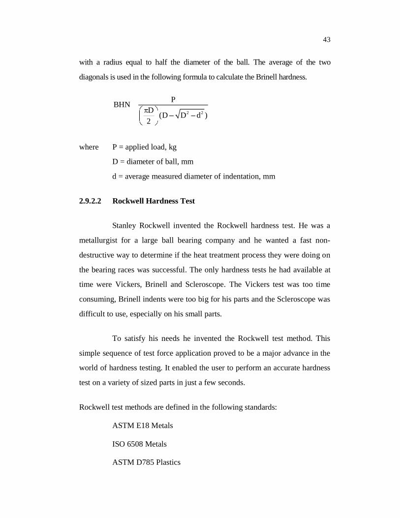
The Brinell hardness number is a function of the test force divided by
the curved surface area of the indent. The indentation is considered to be spherical
43
with a radius equal to half the diameter of the ball. The average of the two
diagonals is used in the following formula to calculate the Brinell hardness.
2 2
PBHND (D D d )2
where P = applied load, kg
D = diameter of ball, mm
d = average measured diameter of indentation, mm
2.9.2.2 Rockwell Hardness Test
Stanley Rockwell invented the Rockwell hardness test. He was a
metallurgist for a large ball bearing company and he wanted a fast non-
destructive way to determine if the heat treatment process they were doing on
the bearing races was successful. The only hardness tests he had available at
time were Vickers, Brinell and Scleroscope. The Vickers test was too time
consuming, Brinell indents were too big for his parts and the Scleroscope was
difficult to use, especially on his small parts.
To satisfy his needs he invented the Rockwell test method. This
simple sequence of test force application proved to be a major advance in the
world of hardness testing. It enabled the user to perform an accurate hardness
test on a variety of sized parts in just a few seconds.
Rockwell test methods are defined in the following standards:
ASTM E18 Metals
ISO 6508 Metals
ASTM D785 Plastics
44
Types of the Rockwell Test
There are two types of Rockwell tests:
Rockwell: The minor load is 10 kgf, the major load is 60, 100, or
150 kgf.
Superficial Rockwell: The minor load is 3 kgf and major loads are
15, 30, or 45 kgf.
In both tests, the indenter may be either a diamond cone or steel
ball, depending upon the characteristics of the material being tested.
Rockwell Scales
Rockwell hardness values are expressed as a combination of a
hardness number and a scale symbol representing the indenter and the minor
and major loads. The hardness number is expressed by the symbol HR and the
scale designation.
There are 30 different scales. The majority of applications are
covered by the Rockwell C and B scales for testing steel, brass, and other
metals. However, the increasing use of materials other than steel and brass as
well as thin materials necessitates a basic knowledge of the factors that must
be considered in choosing the correct scale to ensure an accurate Rockwell
test. The choice is not only between the regular hardness test and superficial
hardness test, with three different major loads for each, but also between the
diamond indenter and the 1/16, 1/8, 1/4 and 1/2 in. diameter steel ball
indenters.
45
If no specification exists or there is doubt about the suitability of
the specified scale, an analysis should be made of the following factors that
control scale selection:
Type of materialSpecimen thicknessTest locationScale limitations
Principle of the Rockwell Test
The indenter moves down into position on the part surface. A
minor load is applied and a zero reference position is established. The major
load is applied for a specified time period (dwell time) beyond zero. The
major load is released leaving the minor load applied. The resulting Rockwell
number represents the difference in depth from the zero reference position as
a result of the application of the major load.
Hardness is a characteristic of a material, not a fundamental
physical property. It is defined as the resistance to indentation, and it is
determined by measuring the permanent depth of the indentation. More
simply put, when using a fixed force (load) and a given indenter, the smaller
the indentation, the harder the material. Indentation hardness value is obtained
by measuring the depth or the area of the indentation using one of over 12
different test methods.
2.9.2.3 Vickers Hardness Test
The Vickers hardness test method, also referred to as a
microhardness test method, is mostly used for small parts, thin sections, or
case depth work. The Vickers method is based on an optical measurement
46
system. The Microhardness test procedure, ASTM E-384, specifies a range of
light loads using a diamond indenter to make an indentation which is
measured and converted to a hardness value. It is very useful for testing on a
wide type of materials as long as test samples are carefully prepared. A square
base pyramid shaped diamond is used for testing in the Vickers scale.
Typically loads are very light, ranging from a few grams to one or several
kilograms, although "Macro" Vickers loads can range up to 30 kg or more.
The Microhardness methods are used to test on metals, ceramics, composites -
almost any type of material.
Since the test indentation is very small in a Vickers test, it is useful
for a variety of applications: testing very thin materials like foils or measuring
the surface of a part, small parts or small areas, measuring individual
microstructures, or measuring the depth of case hardening by sectioning a part
and making a series of indentations to describe a profile of the change in
hardness. The Vickers method is more commonly used.
Sample preparation is usually necessary with a microhardness test
in order to provide a small enough specimen that can fit into the tester.
Additionally, the sample preparation will need to make the specimen’s
surface smooth to permit a regular indentation shape and good measurement,
and to ensure the sample can be held perpendicular to the indenter. Usually,
the prepared samples are mounted in a plastic medium to facilitate the
preparation and testing. The indentations should be as large as possible to
maximize the measurement resolution. (Error is magnified as indentation
sizes decrease) The test procedure is subject to problems of operator influence
on the test results.
Related Documents