Chapter 2: Inside the atom AQA A-Level Physics Teacher Pack 1 | Page 1 | ©HarperCollinsPublishers Limited 2015 Scheme of work Chapter 2: Inside the atom CHAPTER PLANNING Eight hours This chapter reviews what students should have learned at KS4, ready for more in-depth work in Chapter 3 and Chapter 4 on neutrinos and quarks. The chapter is largely descriptive but Lesson 2 allows students to get to grips with some mathematics, following some simple modelling of the atom in Lesson 1. Students may find this second lesson difficult, so you could delay it without loss of continuity or plan to spend some extra time on it. There is no required student practical work in this chapter, although there are opportunities for developing practical skills and for introducing students to a range of new apparatus and techniques. In particular, the practical demonstration using an electron deflection tube in Lesson 2 provides quantitative practical work and requires students to calculate errors from uncertainty in measurements. You should arrange for the use of a Maltese cross tube in Lesson 1. For Lesson 6, you will need a class set of electroscopes, or at least a good demonstration electroscope, and radioactive sources and detectors. You should be aware that although radioactivity is introduced in this chapter, the detail will be covered in Book 2. You will cover the basic particles of radioactivity and decay equations in Lessons 6 and 7, but you will not cover the radioactive decay law. ONE HOUR LESSONS SPECIFICATION CONTENT STUDENT BOOK SECTION 1 The discovery of the electron 3.2.1.1 Simple model of the atom, including the (proton, neutron and) electron (plum pudding model) 2.1 2 The specific charge of the electron 3.2.1.1 Specific charge (of the proton and) the electron, (and of nuclei and ions) 2.1 3 The nuclear model of the atom 3.2.1.1 Simple model of the atom (nuclear model), including the proton, (neutron) and electron 2.2 4 The strong nuclear force 3.2.1.2 The strong nuclear force; its role in keeping the nucleus stable; short-range attraction up to approximately 3 fm, very-short range repulsion closer than approximately 0.5 fm MS 0.2 Use of prefixes for small and large distance measurements 2.3 5 The neutron and isotopes 3.2.1.1 Simple model of the atom, including the proton, neutron and electron Proton number Z, nucleon number A, nuclide notation X A Z Meaning of isotopes and the use of isotopic data Charge and mass of the proton, neutron and electron in SI units and relative units Specific charge of the proton and the electron, and of nuclei and ions 2.3 6 Radioactivity, alpha particles and detectors 3.2.1.2 Unstable nuclei; alpha and beta decay AT l Demonstration of the range of alpha particles using a cloud chamber, spark counter or Geiger counter 2.4 7 Equations for alpha beta and gamma decay 3.2.1.2 Equations for alpha decay, β – decay (the need for the neutrino will be made clear in Chapter 3) 2.4 8 Fundamental interactions 3.2.1.4 Four fundamental interactions (an introduction): gravity, electromagnetic, weak nuclear, strong nuclear 2.5 Sample material, uncorrected proof

Welcome message from author
This document is posted to help you gain knowledge. Please leave a comment to let me know what you think about it! Share it to your friends and learn new things together.
Transcript

Chapter 2: Inside the atom
AQA A-Level Physics Teacher Pack 1 | Page 1 | ©HarperCollinsPublishers Limited 2015
Scheme of work
Chapter 2: Inside the atom
CHAPTER PLANNING
Eight hours
This chapter reviews what students should have learned at KS4, ready for more in-depth work in Chapter 3 and Chapter 4 on neutrinos and quarks. The chapter is largely descriptive but Lesson 2 allows students to get to grips with some mathematics, following some simple modelling of the atom in Lesson 1. Students may find this second lesson difficult, so you could delay it without loss of continuity or plan to spend some extra time on it.
There is no required student practical work in this chapter, although there are opportunities for developing practical skills and for introducing students to a range of new apparatus and techniques. In particular, the practical demonstration using an electron deflection tube in Lesson 2 provides quantitative practical work and requires students to calculate errors from uncertainty in measurements. You should arrange for the use of a Maltese cross tube in Lesson 1. For Lesson 6, you will need a class set of electroscopes, or at least a good demonstration electroscope, and radioactive sources and detectors.
You should be aware that although radioactivity is introduced in this chapter, the detail will be covered in Book 2. You will cover the basic particles of radioactivity and decay equations in Lessons 6 and 7, but you will not cover the radioactive decay law.
ONE HOUR LESSONS SPECIFICATION CONTENT STUDENT BOOK SECTION
1 The discovery of the electron
3.2.1.1 Simple model of the atom, including the (proton, neutron and) electron (plum pudding model)
2.1
2 The specific charge of the electron
3.2.1.1 Specific charge (of the proton and) the electron, (and of nuclei and ions)
2.1
3 The nuclear model of the atom
3.2.1.1 Simple model of the atom (nuclear model), including the proton, (neutron) and electron
2.2
4 The strong nuclear force
3.2.1.2 The strong nuclear force; its role in keeping the nucleus stable; short-range attraction up to approximately 3 fm, very-short range repulsion closer than approximately 0.5 fm
MS 0.2 Use of prefixes for small and large distance measurements
2.3
5 The neutron and isotopes
3.2.1.1 Simple model of the atom, including the proton, neutron and electron
Proton number Z, nucleon number A, nuclide notation XAZ
Meaning of isotopes and the use of isotopic data
Charge and mass of the proton, neutron and electron in SI units and relative units
Specific charge of the proton and the electron, and of nuclei and ions
2.3
6 Radioactivity, alpha particles and detectors
3.2.1.2 Unstable nuclei; alpha and beta decay
AT l Demonstration of the range of alpha particles using a cloud chamber, spark counter or Geiger counter
2.4
7 Equations for alpha beta and gamma decay
3.2.1.2 Equations for alpha decay, β–decay (the need for the neutrino will be made clear in Chapter 3)
2.4
8 Fundamental interactions
3.2.1.4 Four fundamental interactions (an introduction): gravity, electromagnetic, weak nuclear, strong nuclear
2.5
Sample
mate
rial, u
ncorr
ected
proo
f

Chapter 2: Inside the atom
AQA A-Level Physics Teacher Pack 1 | Page 2 | ©HarperCollinsPublishers Limited 2015
PRIOR KNOWLEDGE
Students who have studied GCSE Additional Science are likely to have been taught about the nuclear atom and radioactivity. They are likely to have learned about the forces between electric charges and the meaning of the term ‘potential difference’, and how electrons behave in electric and magnetic fields.
In Chapter 1, students were taught the evidence for the existence of the atom and techniques for measuring its size.
POSSIBLE BARRIERS TO PROGRESS
Students will need good algebraic skills in this chapter. Substituting into formulae and setting up equations are both required skills in understanding how to arrive at the specific charge of the electron. A firm understanding of the nature of the equality in equations which represent nuclear decay is essential if students are to appreciate the conservation laws, which are taught later in the course.
Students may not have a good understanding of the concept of ‘field’ which is used in this chapter. This may need careful management.
WHERE IT LEADS
Students will learn about antiparticles in Chapter 3 and be introduced to the neutrino and the justification for proposing its existence.
Chapter 4 covers the fundamental interactions in terms of exchange particles, quarks and conservation laws. The radioactive decay law will be covered in Book 2.
Sample
mate
rial, u
ncorr
ected
proo
f
Chapter 2: Inside the atom
AQA A-Level Physics Teacher Pack 1 | Page 3 | ©HarperCollinsPublishers Limited 2015
Lesson plan 1
Lesson 1 The discovery of the electron
LEARNING OUTCOMES
Students should be able to: • describe J. J. Thomson’s plum pudding model of the atom • describe the properties of the electron • explain why acceptance of the discovery of the electron was so difficult for scientists in 1900 • appreciate that our knowledge and understanding has developed over time through application of the
scientific method.
POSSIBLE BARRIERS TO PROGRESS
The meaning of the term ‘proportional’ should be made explicitly clear as some students may not have gained a good understanding of this during KS4.
LESSON OUTLINE
Engage and remind
Show three images to students (all easy to locate on the internet):
• Alessandro Volta’s voltaic pile around 1800 • Thomson in his laboratory accelerating ‘cathode rays’ around 1900 • the Diamond Light Source facility in Oxfordshire around 2000.
Point out that there is a century between each image and that each image represents the ultimate in accelerating electrons for that era. One hundred years after the voltaic pile we knew what electric current was. Another one hundred years later, we now have the Diamond Light Source, the world’s brightest source of radiation (X-rays in this case) which uses accelerated electrons.
Core activities
Use a Maltese cross tube, referring to Technician notes 2.1.1 Understanding the Maltese cross tube, to show that ‘something’ is deflected by a magnetic field, taking care with the EHT supply. You should use a magnetic compass to establish the field direction and then demonstrate that Alexander Fleming’s left-hand rule is observed. Some students may already be aware of the motion of electrons in a magnetic field, but they should all be prepared for the next lesson on the specific charge (e/m) of the electron.
When the Maltese cross is not connected to the anode, a clover leaf shape usually appears because the cross itself becomes negatively charged (by the electron beam) and deflects electrons away from the edges. Use this fact to show that the electrons are deflected by an electric field. Ask students to complete Activity sheet 2.1.1 Understanding the Maltese cross tube to check their understanding of the apparatus.
Further guidance on experiments with a Maltese cross tube may be found at www.nuffieldfoundation.org (search for practical physics, then Maltese cross tube). If a Maltese cross tube is unavailable, you can use an oscilloscope and show that the spot is deflected by a magnetic field. Use the Y-plates to show that it is also deflected by an electric field.
Describe Thomson’s process of the discovery of the nature of cathode rays using the journal article presented in Student Book 1, Section 2.1. You will need to explain the terms ‘coaxial’, ‘phosphorescence’ and ‘electrometer’, and ensure that the term ‘proportional’ is fully understood. The importance of the development of technology should be emphasised, in particular high vacuum and high voltage (using induction coils, transformers).
Refer students to Student Book 1, Chapter 2, Assignment 1: Understanding Thomson’s experiments. Students could tackle the assignment questions in groups and provide verbal feedback. These could then be written up, possibly as a homework task.
Consolidate and look ahead
Remind students that the discovery of the electron led to Thomson’s plum pudding model with negative ‘bits’ embedded in a positive matrix. The scene was then set for Ernest Rutherford’s amazing discovery of the nucleus.
Prepare students for the next lesson by explaining that when an electron beam passes through electric and magnetic fields at the same time, the force due to the electric field can be balanced by the force due to the magnetic field. If you feel that students are not ready for the mathematical analysis of the deflection tube experiment in order to find e/m, plan to spend some extra time in preparation for this (using Student Book 1, Chapter 2, Assignment 2: Measuring the specific charge (e/m) of the electron) or delay its implementation until after Lesson 3 or 4.
Sample
mate
rial, u
ncorr
ected
proo
f
Chapter 2: Inside the atom
AQA A-Level Physics Teacher Pack 1 | Page 4 | ©HarperCollinsPublishers Limited 2015
Activity sheet 2.1.1
Understanding the Maltese cross tube
TASK 1
Observe the demonstration of a Maltese cross tube.
TASK 2
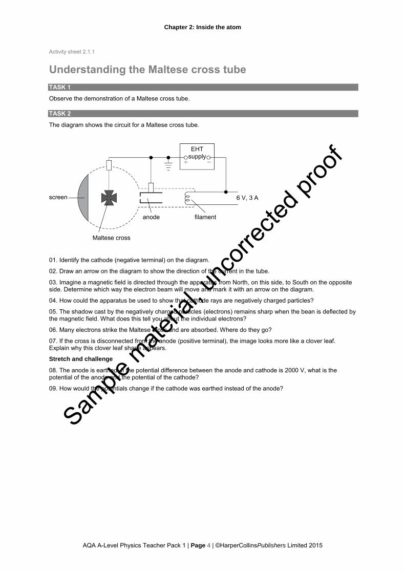
The diagram shows the circuit for a Maltese cross tube.
01. Identify the cathode (negative terminal) on the diagram.
02. Draw an arrow on the diagram to show the direction of the current in the tube.
03. Imagine a magnetic field is directed through the apparatus from North, on this side, to South on the opposite side. Determine which way the electron beam will move and mark it with an arrow on the diagram.
04. How could the apparatus be used to show that cathode rays are negatively charged particles?
05. The shadow cast by the negatively charged particles (electrons) remains sharp when the bean is deflected by the magnetic field. What does this tell you about the individual electrons?
06. Many electrons strike the Maltese cross and are absorbed. Where do they go?
07. If the cross is disconnected from the anode (positive terminal), the image looks more like a clover leaf. Explain why this clover leaf shape appears.
Stretch and challenge
08. The anode is earthed. If the potential difference between the anode and cathode is 2000 V, what is the potential of the anode and the potential of the cathode?
09. How would the potentials change if the cathode was earthed instead of the anode?
Sample
mate
rial, u
ncorr
ected
proo
f
Chapter 2: Inside the atom
AQA A-Level Physics Teacher Pack 1 | Page 5 | ©HarperCollinsPublishers Limited 2015
Technician notes for Activity 2.1.1
Understanding the Maltese cross tube This is a teacher demonstration of a Maltese cross tube.
The Maltese cross tube requires an EHT supply. Precautions should be taken to ensure no one receives a shock.
EQUIPMENT AND MATERIALS
• Maltese cross tube and stand (or, if unavailable, an oscilloscope) • 6 V supply and EHT supply • 2 × bar magnets • magnetic compass
NOTES
Take precautions to ensure that no one receives a shock from the EHT supply. Avoid touching any bare terminals. Shrouded leads should be used where necessary.
The tube itself is very fragile and should be handled with care.
Remember to switch off the filament and turn the anode voltage to zero immediately after the demonstration.
If a Maltese cross tube is unavailable, set up an oscilloscope with a stationary spot and a battery connected to the Y-plates via a switch.
PROCEDURE
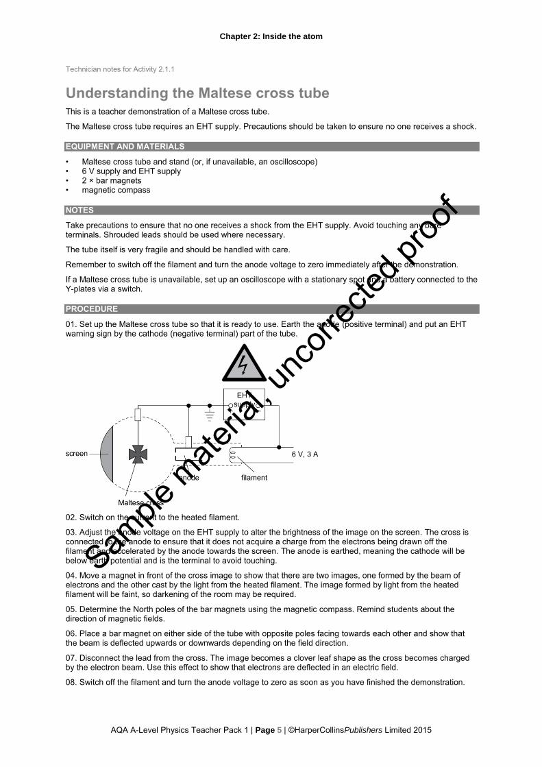
01. Set up the Maltese cross tube so that it is ready to use. Earth the anode (positive terminal) and put an EHT warning sign by the cathode (negative terminal) part of the tube.
02. Switch on the current to the heated filament.
03. Adjust the anode voltage on the EHT supply to alter the brightness of the image on the screen. The cross is connected to the anode to ensure that it does not acquire a charge from the electrons being drawn off the filament and accelerated by the anode towards the screen. The anode is earthed, meaning the cathode will be below earth potential and is the terminal to avoid touching.
04. Move a magnet in front of the cross image to show that there are two images, one formed by the beam of electrons and the other cast by the light from the heated filament. The image formed by light from the heated filament will be faint, so darkening of the room may be required.
05. Determine the North poles of the bar magnets using the magnetic compass. Remind students about the direction of magnetic fields.
06. Place a bar magnet on either side of the tube with opposite poles facing towards each other and show that the beam is deflected upwards or downwards depending on the field direction.
07. Disconnect the lead from the cross. The image becomes a clover leaf shape as the cross becomes charged by the electron beam. Use this effect to show that electrons are deflected in an electric field.
08. Switch off the filament and turn the anode voltage to zero as soon as you have finished the demonstration.
Sample
mate
rial, u
ncorr
ected
proo
f

Chapter 2: Inside the atom
AQA A-Level Physics Teacher Pack 1 | Page 6 | ©HarperCollinsPublishers Limited 2015
Lesson plan 2
Lesson 2 The specific charge of the electron
LEARNING OUTCOMES
Students should be able to: • explain what is meant by ‘specific charge’ • describe how the electric force on a beam of moving electrons can be balanced by the magnetic force • interpret an equation which describes this and substitute in experimental values • use standard form (scientific notation) • estimate and comment on uncertainties in measurements.
POSSIBLE BARRIERS TO PROGRESS
Students are likely to still have difficulty with Fleming’s left-hand rule, particularly when applied to a beam of electrons rather than a current carrying conductor.
LESSON OUTLINE
Engage and remind
Suspend an object from a spring and ask students to describe the forces acting on it. Suggest that this is a balanced situation and that in the electron deflection tube, two forces will be exerted on the moving electrons and these forces will be balanced in a similar way, if the beam is not deflected. Explain to students that the equilibrium position for the object on the spring depends on the mass of the object, whereas for the moving electron, the equilibrium position depends on both the mass and charge on the electron. The ratio of charge to mass, e/m – the ‘specific charge’ on the electron – can be determined, where e is the charge carried by the electron and m is its mass.
Core activities
Use Technician notes for Activity 2.2.1 Calculating e/m for the electron to demonstrate using an electron deflection tube, taking care with the EHT supply. Explain to students how the tube works and make use of Student Book 1, Chapter 2, Assignment 2: Measuring the specific charge (e/m) of the electron to ensure that they are prepared for the analysis required to determine the electron’s specific charge, e/m.
The electron beam in the apparatus is best viewed in a darkened room. Follow the procedure given in the Technician notes to first show that the charge on the beam is negative and then how the beam is deflected in the magnetic field, as predicted by Fleming’s left-hand rule.
When you select a setting for Vd so that the beam is forced back to the horizontal straight line, although not required at this stage, you should equate Eq and Bqv, and point out that the charge q appears to cancel. Do not derive the formula for e/m given in Assignment 2 of the Student Book, but simply point out that it comes from this equality. When you adjust the accelerating potential difference Va to show that this upsets the balance, explain that the speed of the electrons v depends on their charge e and inversely on their mass m, hence the balanced position depends on e/m for the electrons.
Students should record values for the measured and given quantities on Activity sheet 2.2.1 Calculating e/m for the electron. Work through with them the substitution of values into the formulae provided and the calculation of a value for e/m. You may want students to then answer the questions in Task 3: Units, to probe their understanding further.
You might want to select another value for Va and ask students to calculate e/m again. They could then use the Activity sheet 2.2.2 Estimating the uncertainty in e/m to comment on the similarity to the first value by estimating the probable error in e/m. (Many students will find this difficult.)
Note that a straight line graph could be obtained by plotting Vd against I for a given value of Va, but at this stage such a task might cause confusion.
Consolidate and look ahead
Remind students that J. J. Thomson was surprised by the size of e/m, meaning that either the charge was very much larger than expected or the mass of the electron was very much smaller.
You could point out that the electric force depends on q, while the magnetic force depends on a moving q. Ask students to speculate on whether the electric and magnetic force fields might be related in some way, which will prepare them for the last lesson in this chapter.
Sample
mate
rial, u
ncorr
ected
proo
f

Chapter 2: Inside the atom
AQA A-Level Physics Teacher Pack 1 | Page 7 | ©HarperCollinsPublishers Limited 2015
Activity sheet 2.2.1
Calculating e/m for the electron
TASK 1: ELECTRON DEFLECTION TUBE DEMONSTRATION
Observe the demonstration with an electron deflection tube. Record the results.
For a balanced situation, write down the values with units for:
Va =
Vd =
d =
Make sure that d is in metres.
N =
I =
µ0 = 1.26 × 10⁻⁶ N A–2
R =
Make sure that R is in metres.
TASK 2: CALCULATING e/m
Use the results of the electron deflection tube demonstration to calculate e/m, the specific charge of the electron.
Calculate a value for B, the magnetic flux density, in teslas, using:
B =8μ0 NI
5√5R
B =
Now calculate a value for e/m using:
e/m = Vd2
2VaB2d
2
e/m =
TASK 3: UNITS
01. What are the units of B in terms of newtons, amps and metres?
02. Show that the units on the left and right of the equation for e/m are the same.
Sample
mate
rial, u
ncorr
ected
proo
f

Chapter 2: Inside the atom
AQA A-Level Physics Teacher Pack 1 | Page 8 | ©HarperCollinsPublishers Limited 2015
Technician notes for Activity 2.2.1
Calculating e/m for the electron This is a teacher demonstration of an electron deflection tube.
The tube requires an EHT supply. Precautions should be taken to ensure that no one receives a shock.
EQUIPMENT AND MATERIALS
• electron deflection tube with EHT supply and 6 V supply • variable HT supply for deflection plates • Helmholtz coils • LT supply, smoothed (or 12 V car battery, 0–5 A ammeter and 10 A rheostat) for Helmholtz coils
NOTES
Take precautions to ensure that no one receives a shock from the EHT supply. Avoid touching any bare terminals. Shrouded leads should be used where necessary.
If a smoothed LT supply is unavailable, use a 12 V car battery and a rheostat, in series with an ammeter.
Remember to switch off the apparatus immediately after the demonstration.
SET-UP PROCEDURE
01. Connect the filament to the 6 V supply on the EHT unit.
02. Set up the electron deflection tube with the EHT supply connected between the anode and cathode.
03. Earth the anode and provide an EHT warning sign near the cathode.
04. Connect the upper and lower deflection plates to the positive and negative terminals of the HT supply.
05. Connect the earth of the HT supply to the earth of the EHT supply.
06. Make sure the Helmholtz coils are connected in series so that the magnetic field is in the same direction for each, using a smoothed LT supply.
Sample
mate
rial, u
ncorr
ected
proo
f

Chapter 2: Inside the atom
AQA A-Level Physics Teacher Pack 1 | Page 9 | ©HarperCollinsPublishers Limited 2015
Technician notes for Activity 2.2.1 sheet 2
DEMONSTRATION PROCEDURE
The electron beam in the apparatus is best viewed in a darkened room.
01. Switch on the EHT and HT supplies.
02. Keep the accelerating (anode) potential difference Va constant and first have zero current through the Helmholtz coils.
03. Vary the potential difference Vd across the deflection plates and show that the charge on the beam is negative.
04. Then set Vd to zero, turn on the current in the Helmholtz coils and show that the beam is deflected in the magnetic field, in a direction predicted by Fleming’s left-hand rule.
05. Select a suitable setting for Vd so that the beam can be forced back to the horizontal straight line.
06. Adjust the accelerating potential difference Va to show that this upsets the balance.
07. Switch off the apparatus as soon as you have finished the demonstration.
Sample
mate
rial, u
ncorr
ected
proo
f

Chapter 2: Inside the atom
AQA A-Level Physics Teacher Pack 1 | Page 10 | ©HarperCollinsPublishers Limited 2015
Activity sheet 2.2.2
Estimating the uncertainty in e/m
Stretch and challenge
You may want to refer to the rules in Student Book 1, Chapter 1 for combining uncertainties.
01. Use your measurements and calculations from Activity sheet 2.2.1 Calculating e/m for the electron. If possible, calculate a second value for e/m using a second set of results.
02. Choose one set of measurements. Estimate their uncertainties below.
Va = ± % uncertainty =
Vd = ± % uncertainty =
d = ± % uncertainty =
N = assume no uncertainty
I = ± % uncertainty =
µ0 = 1.26 × 10⁻⁶ N A–2, assume no uncertainty
R = ± % uncertainty =
03. From the formula B = 8μ0 NI
5√5R estimate the % uncertainty in B.
04. From the formula e
m=
Vd2
2VaB2d
2 estimate the % uncertainty in e/m.
05. Now calculate the absolute uncertainty in e/m.
06. Write out the calculated value of e/m to the correct number of significant figures with its probable uncertainty.
07. a. Are the two calculated values of e/m consistent with one another? Comment.
b. How do they compare with the actual accepted value? Comment.
Sample
mate
rial, u
ncorr
ected
proo
f

Chapter 2: Inside the atom
AQA A-Level Physics Teacher Pack 1 | Page 11 | ©HarperCollinsPublishers Limited 2015
Lesson plan 3
Lesson 3 The nuclear model of the atom
LEARNING OUTCOMES
Students should be able to: • describe quantitatively the relative dimensions of the atom and its nucleus • describe the concentration of charge and mass in the nucleus • show an appreciation of how Ernest Rutherford concluded that the nucleus existed • appreciate that our knowledge and understanding has developed through use of theories, models and
analysis of experimental results.
THE JOURNEY SO FAR
Students should recall that, by 1909, J. J. Thomson had discovered the electron but was still working on the assumption of the plum pudding model for the atom. e/m for the electron had been measured, suggesting that the electron was very small. The charge on the electron would not be measured accurately until 1911, by Robert Millikan, and this confirmed the small mass of the electron.
LESSON OUTLINE
Engage and remind
Read this quote to students, attributed to Ernest Rutherford: “The energy produced by the breaking down of the atom is a very poor kind of thing. Anyone who expects a source of power from transformations of these atoms is talking moonshine.” Ask students to reflect on the making of unfounded scientific predictions.
Core activities
Describe Hans Geiger and Ernest Marsden’s experiment (1909) in which gold foil was bombarded with alpha particles. Ensure that students have understood the experimental set-up shown in Figure 9 from Student Book 1, Chapter 2. Ask them to estimate the ratio e/m for the alpha particle and compare it to e/m for the electron. Draw out the idea that although we know e/m for each particle, it is difficult to compare them directly if we do not know the charges or the masses. You could refer to Student Book 1, Section 2.4, Alpha radiation which describes how Rutherford had also (in 1909) concluded that alpha particles were doubly charged helium atoms. This meant that he had a very good idea of how the alpha particles should be scattered by a plum pudding atom, hence the great surprise when 1/8000 were scattered backwards: “It was quite the most incredible event that has ever happened to me. It was almost as incredible as if you fired a 15-inch shell at a piece of tissue paper and it came back and hit you.”
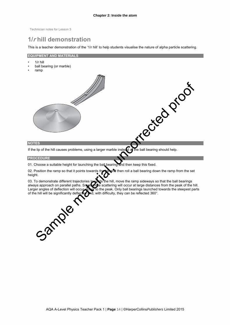
To help students visualise the nature of the alpha particle scattering, if available, you could use a ‘1/r hill’, as outlined in Technician notes for Lesson 3 1/r hill demonstration. Rolling ball bearings from a given height on different parallel trajectories towards the hill should result in small angle scattering at large distances from the peak, and larger angles of deflection closer to the peak. The 1/r shape of the hill produces changes in gravitational potential energy equivalent to electric potential energy changes during coulomb repulsion. You could ask students to estimate where the next hill, or nucleus, would be on this scale if the radius of the peak of the hill represents the atomic nucleus. (It would be about one kilometre away so that it is obvious that most alpha particles would be unscattered, but those very few that approach the nucleus closely will suffer significant deflections.)
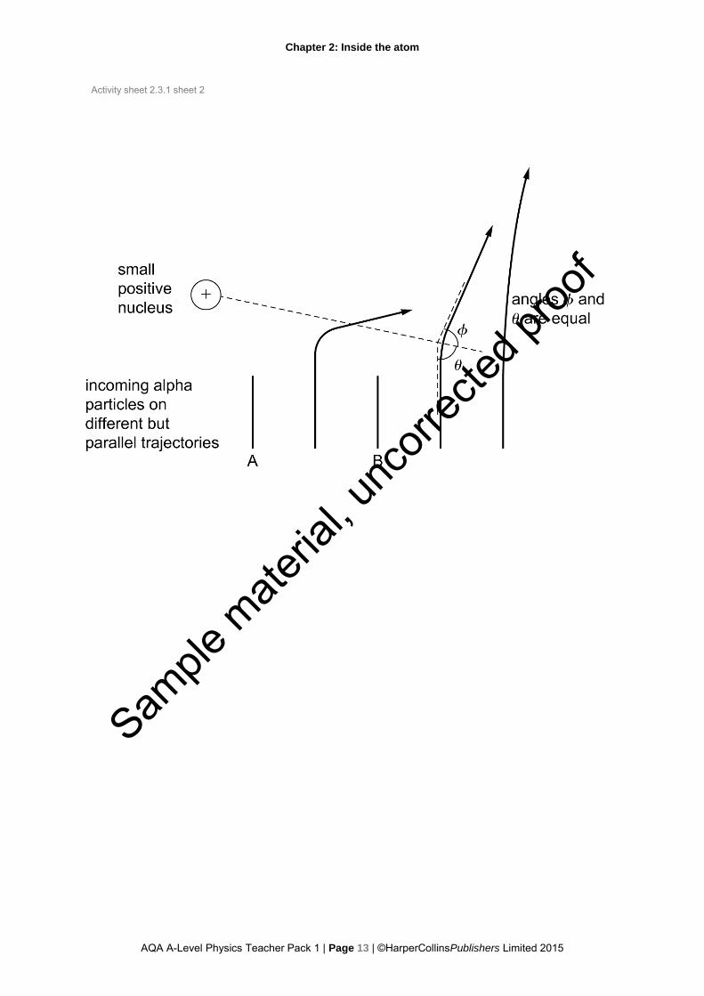
Use the diagram on Activity sheet 2.3.1 Alpha particle scattering, from Rutherford’s original work, to help students understand the nature of the hyperbolic path taken by the scattered alpha particles. The questions on the activity sheet will help to reinforce why the plum pudding model could not stand up to the evidence, and the need for the nuclear model with its concentration of positive charge and mass in the nucleus and relatively huge distance of the electrons from the nucleus.
Consolidate and look ahead
Questions 2 and 3 from Student Book 1, Chapter 2, and questions 4 and 5 on Activity sheet 2.3.1 Alpha particle scattering, should give students a good mental image of the small size of the nucleus compared to the atom. You could also tell them that it has been calculated that if all the space was removed from all the atoms in all the people in the world, the matter from all those people would fit into the size of a sugar cube! Students might want to make up their own similar statement, using the value of the nuclear volume instead of the atomic volume, to astound their friends.
Moving on from this, ask students to consider how the positive particles could be contained in such a small nuclear volume against the repulsive electrostatic forces.
Sample
mate
rial, u
ncorr
ected
proo
f
Chapter 2: Inside the atom
AQA A-Level Physics Teacher Pack 1 | Page 12 | ©HarperCollinsPublishers Limited 2015
Activity sheet 2.3.1
Alpha particle scattering
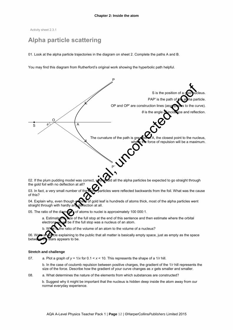
01. Look at the alpha particle trajectories in the diagram on sheet 2. Complete the paths A and B.
You may find this diagram from Rutherford’s original work showing the hyperbolic path helpful.
S is the position of a gold nucleus.
PAP′ is the path of the alpha particle.
OP and OP′ are construction lines (asymptotes to the curve).
θ is the angle of incidence and reflection.
The curvature of the path is greatest at A, the closest point to the nucleus, where the force of repulsion will be a maximum.
02. If the plum pudding model was correct, why would all the alpha particles be expected to go straight through the gold foil with no deflection at all?
03. In fact, a very small number of the alpha particles were reflected backwards from the foil. What was the cause of this?
04. Explain why, even though a sheet of gold leaf is hundreds of atoms thick, most of the alpha particles went straight through with hardly any deflection at all.
05. The ratio of the diameters of atoms to nuclei is approximately 100 000:1.
a. Estimate the size of the full stop at the end of this sentence and then estimate where the orbital electrons would be if the full stop was a nucleus of an atom.
b. What is the ratio of the volume of an atom to the volume of a nucleus?
06. Write an article explaining to the public that all matter is basically empty space, just as empty as the space between the stars appears to be.
Stretch and challenge
07. a. Plot a graph of y = 1/x for 0.1 < x < 10. This represents the shape of a 1/r hill.
b. In the case of coulomb repulsion between positive charges, the gradient of the 1/r hill represents the size of the force. Describe how the gradient of your curve changes as x gets smaller and smaller.
08. a. What determines the nature of the elements from which substances are constructed?
b. Suggest why it might be important that the nucleus is hidden deep inside the atom away from our normal everyday experience.
Sample
mate
rial, u
ncorr
ected
proo
f
Chapter 2: Inside the atom
AQA A-Level Physics Teacher Pack 1 | Page 13 | ©HarperCollinsPublishers Limited 2015
Activity sheet 2.3.1 sheet 2
Sample
mate
rial, u
ncorr
ected
proo
f
Chapter 2: Inside the atom
AQA A-Level Physics Teacher Pack 1 | Page 14 | ©HarperCollinsPublishers Limited 2015
Technician notes for Lesson 3
1/r hill demonstration This is a teacher demonstration of the ‘1/r hill’ to help students visualise the nature of alpha particle scattering.
EQUIPMENT AND MATERIALS
• 1/r hill • ball bearing (or marble) • ramp
NOTES
If the lip of the hill causes problems, using a larger marble instead of the ball bearing should help.
PROCEDURE
01. Choose a suitable height for launching the ball bearing and then keep this fixed.
02. Position the ramp so that it points towards the hill and then roll a ball bearing down the ramp from the set height.
03. To demonstrate different trajectories towards the hill, move the ramp sideways so that the ball bearings always approach on parallel paths. Small angle scattering will occur at large distances from the peak of the hill. Larger angles of deflection will occur closer to the peak. Only ball bearings launched towards the steepest parts of the hill will be significantly deflected and, with difficulty, they can be reflected 360°.
Sample
mate
rial, u
ncorr
ected
proo
f

Chapter 2: Inside the atom
AQA A-Level Physics Teacher Pack 1 | Page 15 | ©HarperCollinsPublishers Limited 2015
Lesson plan 4
Lesson 4 The strong nuclear force
LEARNING OUTCOMES
Students should be able to:
• explain why a strong force is needed to explain the nuclear model • describe the way the force between two protons changes as they are brought closer together • interpret force–distance graphs for the nuclear and electrostatic forces in relation to nucleon separation.
THE JOURNEY SO FAR
Students have seen that moving electrons experience forces in electric and magnetic fields. They should realise that if the nucleus really contains all the positive charges in close proximity, these charges would be repelled from each other with great force due to electrostatic repulsion.
POSSIBLE BARRIERS TO PROGRESS
Students who have completed the Edexcel GCSE syllabus will know about quarks and the strong interaction. The strong interaction between quarks (which will be dealt with in Chapter 4) and the strong nuclear force are not synonymous, but there is a residual effect of the strong interaction just beyond nucleons. It is this residual effect that is called the ‘strong nuclear force’. This strong nuclear force holds protons together in a nucleus against the electrostatic force of repulsion.
LESSON OUTLINE
Engage and remind
Remind students that the force between atoms in molecules is an electrostatic one. The net force of repulsion between like charges is balanced by the net force of attraction between opposite charges, so that ions (in the case of ionically bonded molecules) sit at equilibrium distances from each other. Point out that a net force of attraction alone cannot be the whole story. The resultant force on the ions must be zero for an equilibrium position, which means that a force of repulsion must balance the force of attraction.
Core activities
In the case of the nucleus itself, all the positive charges are in close proximity so there must be another way to oppose and balance the very extreme size of the electrostatic repulsion. Use Technician notes for Lesson 4 Combining forces demonstration to model two dynamics trolleys being repelled from each other by a magnetic force and being attracted to each other by an elastic force. This shows how two different forces result in the trolleys sitting at an equilibrium separation. Pull the trolleys apart slightly, or push them together slightly, to show that the trolleys return to the equilibrium position.
Lead on to the idea that a force of attraction very much stronger than the electrostatic repulsion is needed to explain the fact that protons sit at an equilibrium position very close to each other. This force is the strong nuclear force and because it cannot be felt beyond the nucleus, it must tend very rapidly to zero with distance.
Ask students to examine the three graphs from Student Book 1, Chapter 2 (Figures 11, 12 and 13). First they should note that the nuclear force can be both repulsive (at very small separations) and attractive, and that the attractive force is shown as negative. (A repulsive force acts in the same direction as increasing separation, which is why it is considered positive.) In contrast, the electrostatic force between two protons is always repulsive.
Ask the students:
• to draw a conclusion about the possible size of the proton using Figure 11 • to explain, using Figure 13, what will happen to the protons if their separation increases and reaches 2 fm. (If
the protons are moved slightly closer the attractive force will pull them together until the equilibrium point is reached; if they are moved slightly further apart, the repulsive force will repel the protons apart indefinitely.)
Use Activity sheet 2.4.1 Combining the strong nuclear force and the electrostatic force which asks students to add the electrostatic force of repulsion and nuclear force together. This should convince them that an equilibrium position results.
Consolidate and look ahead
The plum pudding model explained how the electrons were held together within a positive matrix. The nuclear model requires the existence of a completely new force, the strong nuclear force. This force, repulsive at very short range but strongly attractive at longer range, falls off to zero very rapidly with increasing separation. Something else is needed to provide an attractive force at greater separations in nuclei of greater size. This turns out to be the neutron, which of course feels no electrostatic force of repulsion.
Sample
mate
rial, u
ncorr
ected
proo
f

Chapter 2: Inside the atom
AQA A-Level Physics Teacher Pack 1 | Page 16 | ©HarperCollinsPublishers Limited 2015
Activity sheet 2.4.1
Combining the strong nuclear and the electrostatic force In this activity you will add two functions together to produce a third function. Force is a vector quantity. The two functions plotted in the graph describe the variation of the repulsive electrostatic force (positive curve) and the nuclear force (lower curve) along a line joining the centres of two protons.
01. At different points along the Separation axis, add the two force values together (remembering that a value below the axis is negative) to find and plot the resultant force between the two protons. Put a scale on the Separation axis. Indicate the nature of the force (repulsive or attractive) on the Force axis.
02. Describe the way in which the nuclear force varies.
03. Describe the way in which the resultant force varies.
04. a. Mark on your curve the two points where the resultant force is zero.
b. Which of these points is the equilibrium position for the two protons?
Sample
mate
rial, u
ncorr
ected
proo
f
Chapter 2: Inside the atom
AQA A-Level Physics Teacher Pack 1 | Page 17 | ©HarperCollinsPublishers Limited 2015
Technician notes for Lesson 4
Combining forces demonstration This is a teacher demonstration of two different forces acting in equilibrium.
EQUIPMENT AND MATERIALS
• 2 × dynamics trolleys (or similar) • 2 × Magnadur magnets (or similar) • 2 × springs (or four if necessary) • Blu-Tack
PROCEDURE
01. Attach the two magnets to the ends of the trolleys so that the like poles face each other and they are repelled.
02. Join the trolleys together using the springs so that they remain in equilibrium a few centimetres apart. You may need to join multiple springs in series to make a longer, weaker spring, depending on the strength of the magnets.
03. Pull the trolleys apart slightly, or push them together slightly, to show that the trolleys return to the equilibrium position.
Sample
mate
rial, u
ncorr
ected
proo
f

Chapter 5: Waves
AQA A-Level Physics Teacher Pack 1 | Page 2 | ©HarperCollinsPublishers Limited 2015
Lesson plan 5.7
Lesson 5.7 Stationary waves on a string
LEARNING OUTCOMES
In this lesson students carry out Required practical 1: Investigation into the variation of the frequency of stationary waves on a string with length, tension and mass per unit length of the string. This is compulsory for A-Level students and provides them with opportunities to develop and demonstrate (and for you to assess) their mastery of the following practical competencies: • follows written procedures • applies investigative approaches and methods when using instruments and equipment • safely uses a range of practical equipment and materials • makes and records observations. and their skills in using apparatus and techniques in the following areas: • use appropriate analogue apparatus to record a range of measurements and to interpolate between scale
markings • use appropriate digital instruments to obtain a range of measurements • use methods to increase accuracy of measurements • use a signal generator (and oscilloscope) • generate and measure waves using a vibration transducer.
It is strongly advised that AS students also complete this required practical, as they can expect questions based on it in their examination Paper 2. As with all practical work, it will help to develop their hands-on skills and their understanding of the scientific process through investigation.
THE JOURNEY SO FAR
Students have learned that two waves of the same frequency with a fixed phase difference, travelling in opposite directions, superpose to create a stationary wave, and that such a situation is set up when a wave is reflected.
Students will need to be familiar with the apparatus, techniques and mathematics required before they embark on their assessed practical work. Student Book 1, Chapter 5, Required practical 1 introduces students to all of these aspects. Working through these in an earlier lesson, together with a teacher demonstration of the apparatus, is essential.
LESSON OUTLINE
Engage and remind
Remind students what they are going to do in this lesson. Show them the apparatus and ensure that they all have a copy of Activity sheet 5.7.1 Investigating the variation of frequency of stationary waves on a string. This will guide them through their practical work and how to record and analyse their results. Although students will do the practical work in groups, those who are A-Level candidates must independently record their results and analysis.
Core activities
Ensure that students know what is meant by ‘the first harmonic’ and refer them to Student Book 1, Chapter 5. Refer to Technician notes for Activity 5.7.1 to set up the practical. Give students a rough value for setting up the first harmonic for the lightest string. The aim is to verify that f = (1/2l)√(T/μ), so students need to carry out three separate experiments, varying in turn T (tension), µ (mass per unit length) and l (length). You may need to allow two lessons to complete the work. You could reduce the scope for AS-only students.
The signal generator may not give an accurate value of the frequency. A-Level students should, if possible, be given enough time to increase the accuracy of f by taking measurements for the second and possibly third harmonics as well as the first. Ensure that students understand the simple relationship between the frequencies for the different harmonics on a string, and they understand that the averaging reduces the overall uncertainty.
Some A-Level students could construct a calibration curve for the signal generator frequency, using an oscilloscope. See the Stretch and challenge section at the end of Activity sheet 5.7.1. Alternatively, a stroboscope could be used to construct a calibration curve, but this device is just as likely to be as badly calibrated as the signal generator, and care should be taken with its use as the flashing light can induce epileptic episodes. It is also likely to be very distracting for other students in the room.
Consolidate and look ahead
Ensure that all students have their results and their estimated uncertainties recorded by the end of the lesson. They can draw their graphs in the next lesson or for homework.
Sample
mate
rial, u
ncorr
ected
proo
f

Chapter 5: Waves
AQA A-Level Physics Teacher Pack 1 | Page 3 | ©HarperCollinsPublishers Limited 2015
Activity sheet 5.7.1
Investigating the variation of frequency of stationary waves on a string
THE INVESTIGATION
The purpose of this investigation is to find out how the frequency of stationary waves on a string varies with the length l, tension T and mass per unit length µ of the string.
The relationship you will be testing is:
f = 1
2l × √T
μ
which will mean adjusting T, µ and l independently, in three separate investigations.
EQUIPMENT AND MATERIALS
Your group will need:
• 1 m lengths of different string (or several identical pieces of light string to entwine to make heavier samples) • retort stand • G clamp • vibration transducer • paper clip (or short length of thin wire) • signal generator • bench pulley • mass hanger • 10 × 100 g masses • metre ruler • 2 × 4 mm leads You will also need access to: • top-loading balance( for measuring the mass of the string) • long lengths of the string (in order to make accurate measurements of the mass per unit length) • oscilloscope • strobe lamp Before starting the investigation, tell your teacher if flashing lights can put you at risk of an epileptic attack.
PROCEDURE
Fix the string to the retort stand and use the G clamp to fix the stand to the table. Then attach the post of the vibration transducer to the string using a paper clip or short length of thin wire.
The first harmonic is the fundamental mode of vibration for a string, with a node at each end and an antinode in the middle. You will be finding the frequency of vibration for this resonance situation.
Sample
mate
rial, u
ncorr
ected
proo
f

Chapter 5: Waves
AQA A-Level Physics Teacher Pack 1 | Page 4 | ©HarperCollinsPublishers Limited 2015
Activity sheet 5.7.1 sheet 2
You will carry out three separate investigations:
01. Changing T, the tension in the string, and finding the first harmonic resonant frequency for different values of T.
02. Changing µ, the mass per unit length of the string, and finding the first harmonic resonant frequency for different values of µ.
03. Changing l, the length of the string, and finding the first harmonic resonant frequency for different values of l.
When changing T and µ, you are effectively altering the speed of the wave along the string and this affects the frequency of vibration.
For the initial set up, make sure that the amplitude control on the signal generator is not at zero. Set the tension to about 5 N (using 5 × 100 g masses), set the length to about 0.8 m, and adjust the frequency of the signal generator until the first harmonic is obtained. Maximum amplitude of the string vibration will determine the resonant frequency. Turn the amplitude control down if the string’s amplitude is too large.
For each of the three investigations, construct a table to record your values of f, T, µ and l.
Investigation 1: Changing T
01. Set the length of the string to about 0.8 m and use the lightest string (or just one strand if you have several identical pieces of string).
02. Find the resonant first harmonic frequency for five different values of T, by adjusting the number of 100 g masses on the hanger.
03. Plot a graph of f/Hz against √(T/N).
04. Estimate the uncertainty in finding f and draw error bars on the graph before drawing a straight line of best fit.
05. If you have time, you can improve the accuracy of f by finding the frequency of vibration for the second or third harmonic (two and three antinodes respectively) and dividing by 2 or 3 respectively. Then find an average for the first harmonic frequency, for each value of T.
Investigation 2: Changing µ
01. Set the length of the string to about 0.8 m and set the tension to 5 N (using 5 x 100 g masses).
02. For five different weights of string, find the first harmonic frequency.
03. To find µ, the mass per unit length of the string, measure a length of string and weigh it on the top-loading balance. Record the measurements and calculate values of µ to the correct number of significant figures.
04. Plot a graph of f/Hz against 1/√(µ/kg m–1).
05. Estimate the uncertainty in finding f and draw error bars on the graph before drawing a straight line of best fit.
06. Again, if you have time, improve the accuracy of f by finding the frequency of vibration for the second or third harmonic, dividing by 2 or 3 respectively, and then finding an average for the first harmonic frequency , for each value of µ.
Investigation 3: Changing l
01. Set the tension to 5 N (using 5 × 100 g masses) and use the lightest string (or just one strand if you have several identical pieces of string).
02. For five different lengths of string, find the first harmonic frequency. Alter the length of the string by moving the vibration transducer with its paperclip attachment along the string. There is no need to move the retort stand.
03. Plot a graph of f/Hz against 1/(l/m).
04. Estimate the uncertainty in finding f and draw error bars on the graph before drawing a straight line of best fit.
05. Again, if you have time, improve the accuracy of f by finding the frequency of vibration for the second or third harmonic, dividing by 2 or 3 respectively, and then finding an average for the first harmonic frequency , for each value of l.
Sample
mate
rial, u
ncorr
ected
proo
f

Chapter 5: Waves
AQA A-Level Physics Teacher Pack 1 | Page 5 | ©HarperCollinsPublishers Limited 2015
Activity sheet 5.7.1 sheet 3
DATA ANALYSIS
01. Make a comment about how well each straight line fits the points. Does it pass within all the frequency error bars?
02. Estimate the uncertainties in the values of the independent variables, T, l and µ. Draw horizontal error bars on your graphs and comment on whether or not the straight lines are within the horizontal error bars as well as the vertical ones.
03. Can you draw a conclusion from your results?
Stretch and challenge
The signal generator may not give an accurate value of the frequency. To make your results more accurate, you can construct a calibration curve. If the signal generator was used across just one of its ranges, then only one curve need be constructed. If two or more ranges were used, then a curve for each range should be constructed.
01. Plug the vibration transducer into an oscilloscope. A rough guide to setting up the oscilloscope is to turn all knobs to the left and make sure all buttons are out.
02. Measure the frequency for a number of transducer frequencies (about six). This can be done by adjusting the time base until approximately one complete wave is seen on the screen. The time base will provide the number of seconds per division on the screen. Count the number of divisions occupied by the wavelength to measure the period of the wave.
03. The frequency is simply 1/period, or the reciprocal of the period.
04. Plot a graph of oscilloscope frequency against transducer frequency and draw a line of best fit through the points.
05. Now, for any particular frequency in the three investigations, the true frequency can be read off the calibration curve.
Sample
mate
rial, u
ncorr
ected
proo
f

Chapter 5: Waves
AQA A-Level Physics Teacher Pack 1 | Page 6 | ©HarperCollinsPublishers Limited 2015
Technician notes for Activity 5.7.1
Investigating the variation of frequency of stationary waves on a string
EQUIPMENT AND MATERIALS
Each group of students will need:
• 1 m lengths of 5 different types of string (or several identical pieces of light string for students to entwine to make heavier samples)
• retort stand • G clamp • vibration transducer • paper clip (or short length of thin wire) • signal generator • bench pulley • mass hanger • 10 × 100 g masses • metre ruler • 2 × 4 mm leads Also have available: • top-loading balance( for measuring the mass of the string) • long lengths of the string (in order for students to make accurate measurements of the mass per unit length) • oscilloscope with bnc to 4 mm socket connected • strobe lamp Before starting the investigation, establish whether any students are at risk of an epileptic attack from the flashing lights.
NOTES
Each group of students will need sufficient space, the length of a typical table, say 1.5 m.
It is suggested that students attach the end of the string to the retort stand, which is attached to the bench using the G clamp, rather than attaching the end of the string directly to the vibration transducer. The post of the transducer can then be attached to the string using a paper clip (or short length of thin wire). This will reduce the risk of damage to the vibration transducer and make it easier to change the length of the string by moving the transducer along the length of string.
Make sure that the vibration transducer is connected to the low impedance outlet of the signal generator, probably marked 4 Ω.
Sample
mate
rial, u
ncorr
ected
proo
f
Related Documents