Chapter 2 GEOLOGY

Chapter 2 GEOLOGY. Geologists Wellside Exploitation Sedimentologist.
Dec 17, 2015
Welcome message from author
This document is posted to help you gain knowledge. Please leave a comment to let me know what you think about it! Share it to your friends and learn new things together.
Transcript
Chapter 2
GEOLOGY
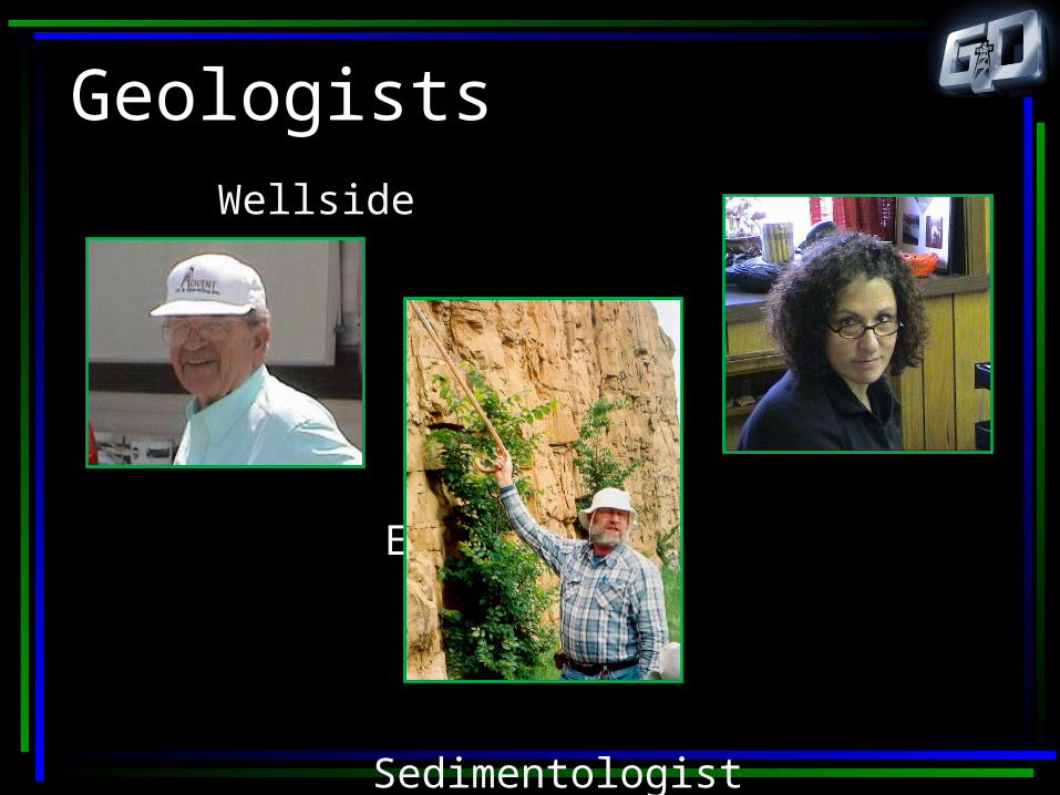
Geologists Wellside
Exploitation
Sedimentologist

Chapter 2
Where were the hydrocarbons?
Cherokee Beach Sands
Shoestring Sands
Previous Geologic Models

Chapter 2
Where are the hydrocarbons?
What is the current geologic model?
Chapter 2
Where and in what direction should I plan my well path?
Chapter 2
Is there a preferential direction to permeability?
Chapter 2
Is directional permeability a result of depositional systems
or fractures or both?

Where are the Hydrocarbons?Vertical wells require: Pre-drill estimate of oil in place
Log evaluations
Post-drill estimate of oil in place to select the perforating interval and turn the well over to production.
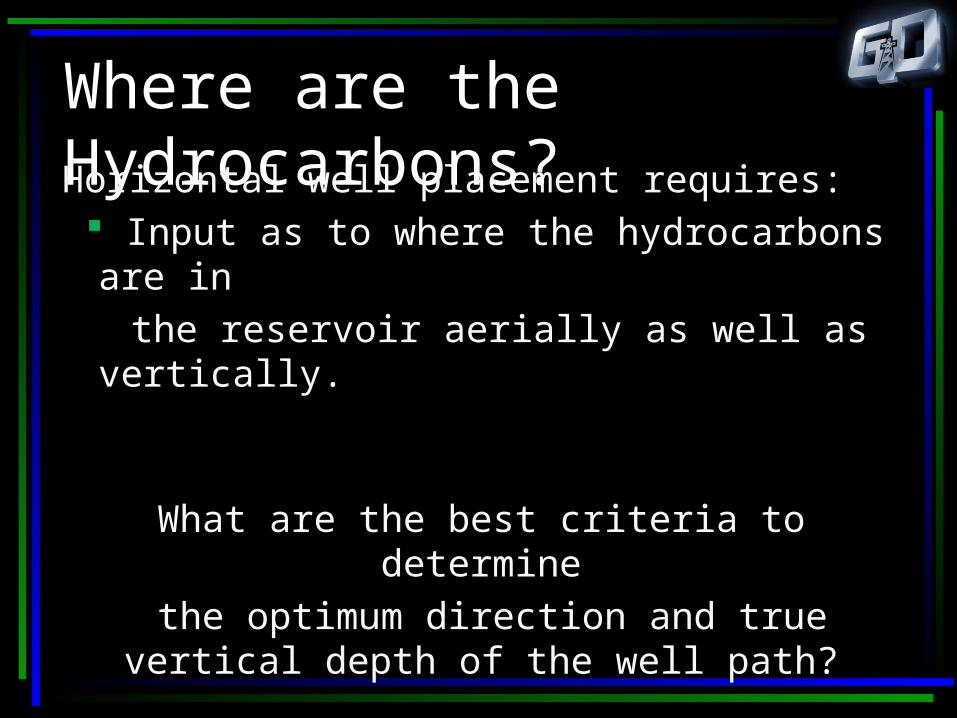
Where are the Hydrocarbons?Horizontal well placement requires: Input as to where the hydrocarbons are in the reservoir aerially as well as vertically.
What are the best criteria to determine the optimum direction and true vertical
depth of the well path?
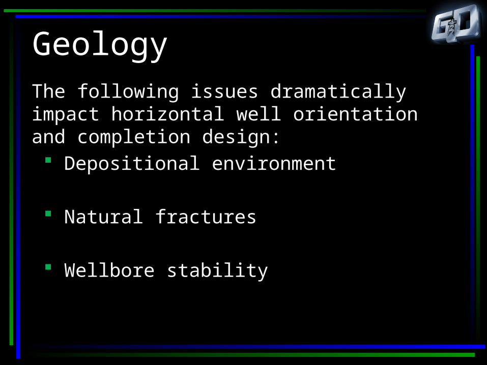
GeologyThe following issues dramatically impact horizontal well orientation and completion design: Depositional environment
Natural fractures
Wellbore stability

GeologyAn accurate description of YOUR field is critical to the success of the horizontal
project.
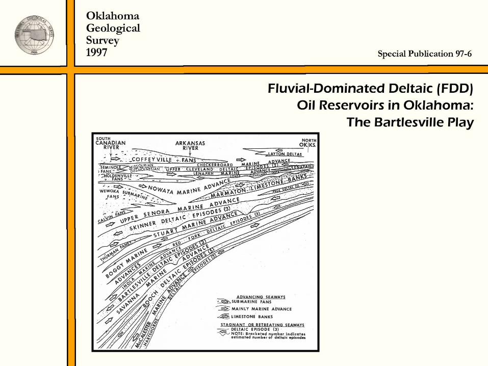
This workshop will concentrate on Pennsylvanian Sandstone Reservoirs.
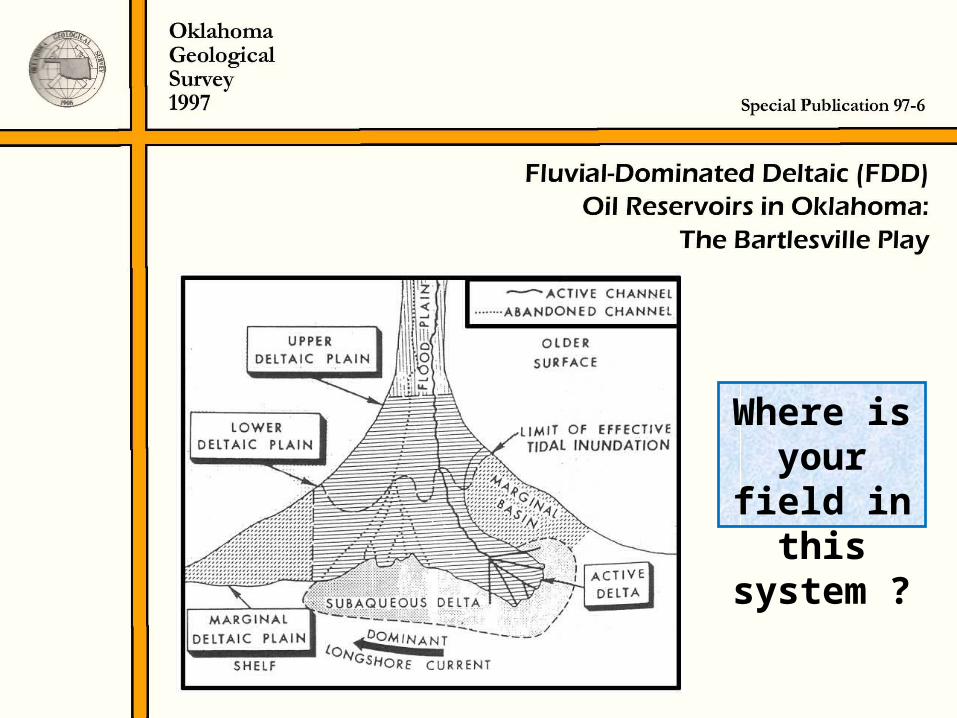
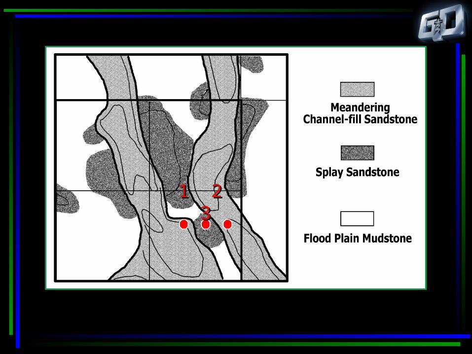
Where is your
field in this
system ?

Where would
you put the
horizontal well?

How do you
decide well
direction?

Should you drill
parallel or transverse?

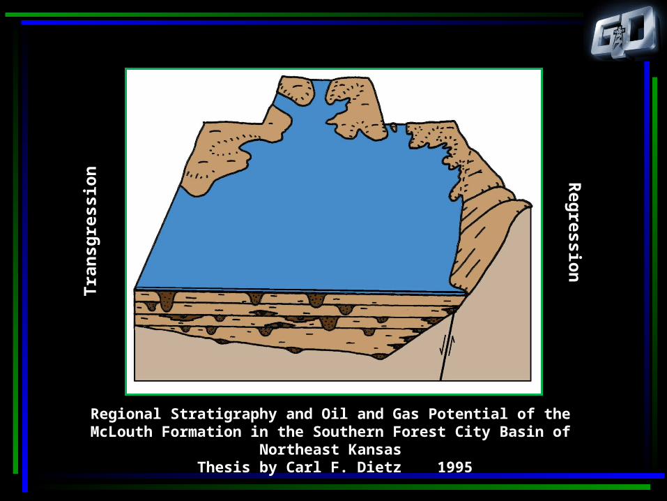
Regional Stratigraphy and Oil and Gas Potential of the McLouth Formation in the Southern Forest City Basin of Northeast Kansas
Thesis by Carl F. Dietz 1995
Regional Stratigraphy and Oil and Gas Potential of the McLouth Formation in the Southern Forest City Basin of Northeast Kansas
Thesis by Carl F. Dietz 1995
Reg
ression
Tra
nsg
ress
ion
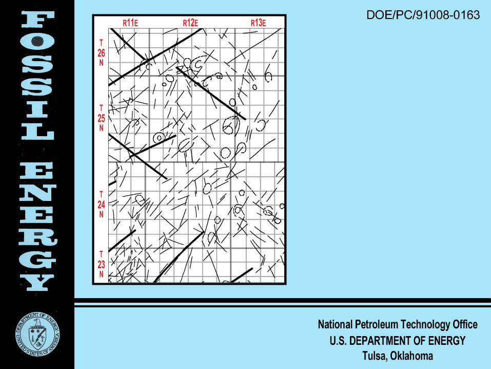
OSTI_ID: 3244
A NEW METHODOLOGY FOR OIL AND GAS EXPLORATION USINGREMOTE SENSING DATA AND SURFACE FRACTURE ANALYSIS
Topical ReportAugust 1995
ByGenliang GuoHerbert B. Carroll
February 1999
Performed Under Contract No. DE-AC22-94PC91008(Original Report Number NIPER/BDM-0163)
BDM-Oklahoma, Inc.Bartlesville, Oklahoma

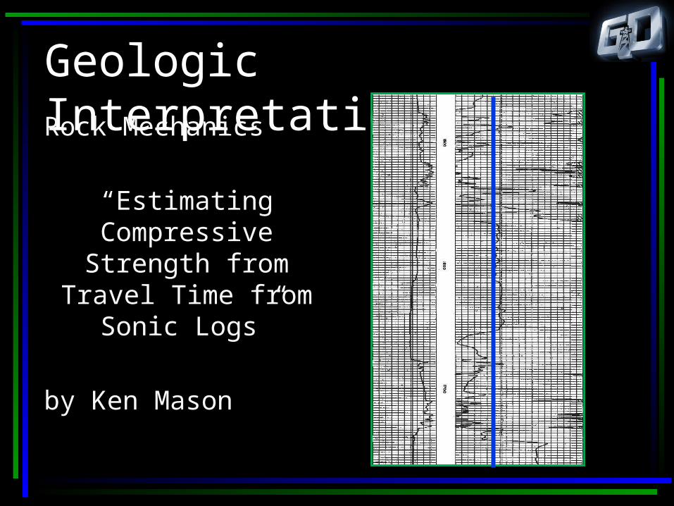
Geologic InterpretationsRock Mechanics
“Estimating Compressive
Strength from Travel Time from Sonic
Logs”
by Ken Mason
Rock MechanicsThe answer to the wellbore stability question will determine completion technique: Open-hole completion
Slotted liner
Cemented liner/casing
Geology Formation dip and strike
Faults - 3D display
Reservoir continuity

The Bartlesville “Zones”
“C”
“D”

“D”
“C”

1 2 31 2 3
1 2 31 2 3
DGI E
What does the Bartlesville
look like on an induction log?
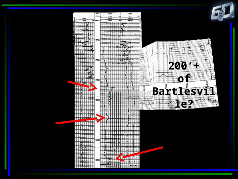
200’+of
Bartlesville?
Perf here?
Here?
and/or here?
What does a horizontal well in the Bartlesville look like on an induction log?
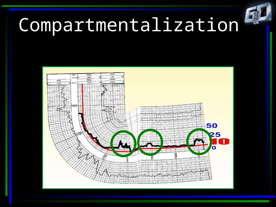
Compartmentalization

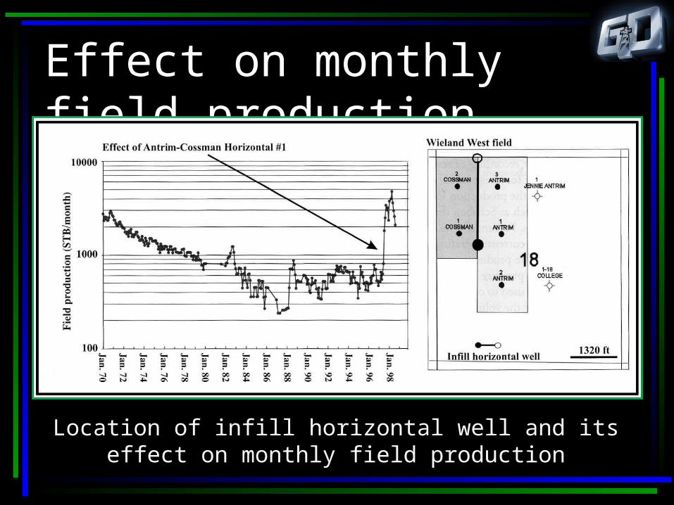
Effect on monthly field production
Location of infill horizontal well and its effect on monthly field production

Geology Conclusion Determine target direction and true vertical depth.
Determine target window based on target thickness, strike and dip.
Consider lease lines and required legal spacing.
Consider rock mechanics in the completion design.
Related Documents