Design for Strength and Endurance – Chapter 2 _____________________________________________________________________________________ Two Dimensional Stresses - 29 - C.F. Zorowski 2002 Chapter 2 Two Dimensional Stress Analysis Screen Titles Definitions – Stress Components Rectilinear Components Rotated Stress System Normal Stress – X’ direction Shear Stress – Y’ direction Normal Stress – Y’ direction Double Angle Formulation Average Stress (introduction) Average Stress (continuation) Graphical Interpretation Principal Stresses Mohr’s Circle Construction Orientation – Principal Stresses General Stress State Principal Stresses – 3D Orientation Principal Stress Equation – 3D Mohr’s Circle – 3D Stress State Review Exercise Off line Exercise

Welcome message from author
This document is posted to help you gain knowledge. Please leave a comment to let me know what you think about it! Share it to your friends and learn new things together.
Transcript
Design for Strength and Endurance – Chapter 2
_____________________________________________________________________________________Two Dimensional Stresses - 29 - C.F. Zorowski 2002
Chapter 2 Two Dimensional Stress Analysis
Screen Titles
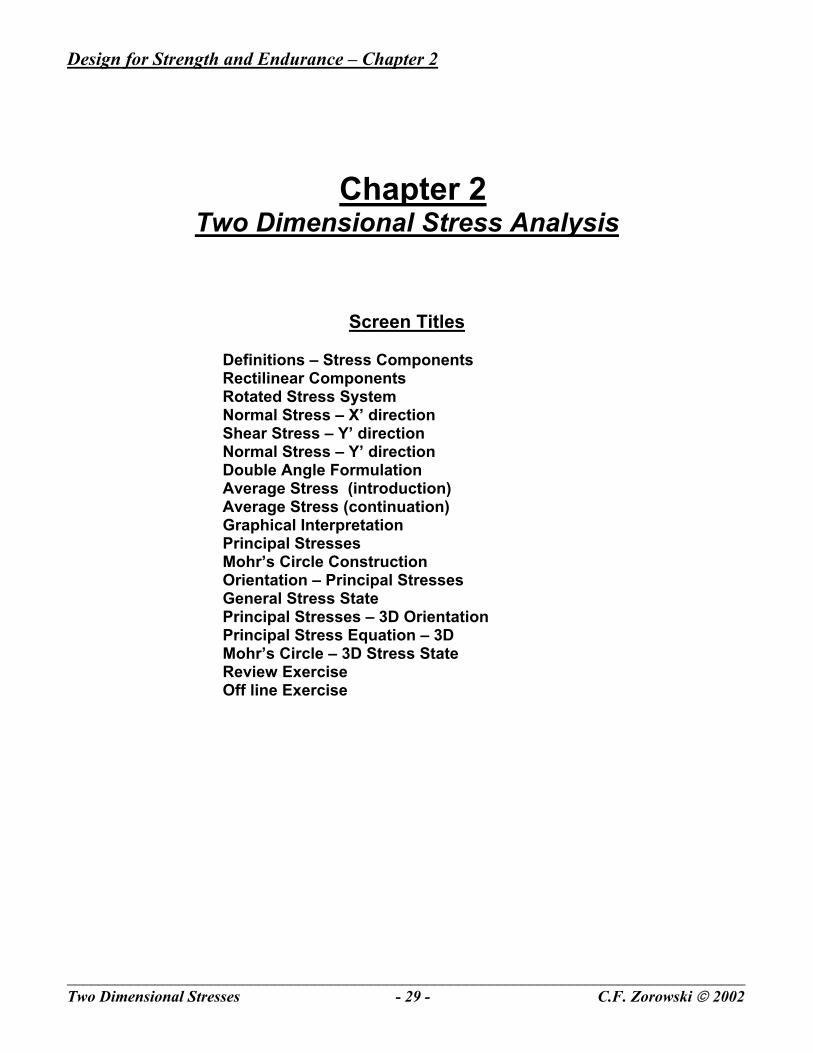
Definitions – Stress Components Rectilinear Components Rotated Stress System Normal Stress – X’ direction Shear Stress – Y’ direction Normal Stress – Y’ direction Double Angle Formulation Average Stress (introduction) Average Stress (continuation) Graphical Interpretation Principal Stresses Mohr’s Circle Construction Orientation – Principal Stresses General Stress State Principal Stresses – 3D Orientation Principal Stress Equation – 3D Mohr’s Circle – 3D Stress State Review Exercise Off line Exercise

Design for Strength and Endurance – Chapter 2
_____________________________________________________________________________________Two Dimensional Stresses - 30 - C.F. Zorowski 2002

Design for Strength and Endurance – Chapter 2
_____________________________________________________________________________________Two Dimensional Stresses - 31 - C.F. Zorowski 2002
1. Title page Chapter two covers the definition and analysis of a two dimensional rectilinear state of stress involving both normal and shear components. The topics discussed include the equilibrium of cross shear stresses, development of the equations defining stress components with respect to a rotated axis system, graphical interpretation of rotated axis system stress equations, principal stress components, Mohr’s circle construction and use together with a brief introduction to the analysis of a generalized three dimensional state of stress. Several sample problems demonstrating the application of the theory presented are also included.
2. Page Index Listed on this page are all the individual pages in Chapter 2 with the exception of the sample problems. Each title is hyperlinked to its specific page and can be accessed by clicking on the title. It is suggested that the reader first proceed through all pages sequentially. Clicking on the text button at the bottom of the page provides a pop up window with the text for that page. The text page is closed by clicking on the x in the top right corner of the frame. Clicking on the index button returns the presentation to the chapter page index.
Design for Strength and Endurance – Chapter 2
_____________________________________________________________________________________Two Dimensional Stresses - 32 - C.F. Zorowski 2002
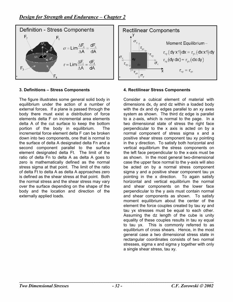
3. Definitions – Stress Components The figure illustrates some general solid body in equilibrium under the action of a number of external forces. If a plane is passed through the body there must exist a distribution of force elements delta F on incremental area elements delta A of the cut surface to keep the bottom portion of the body in equilibrium. The incremental force element delta F can be broken down into two components, one that is normal to the surface of delta A designated delta Fn and a second component parallel to the surface element designated delta Ft. The limit of the ratio of delta Fn to delta A as delta A goes to zero is mathematically defined as the normal stress sigma at that point. The limit of the ratio of delta Ft to delta A as delta A approaches zero is defined as the shear stress at that point. Both the normal stress and the shear stress may vary over the surface depending on the shape of the body and the location and direction of the externally applied loads.
4. Rectilinear Stress Components Consider a cubical element of material with dimensions dx, dy and dz within a loaded body with the dx and dy edges parallel to an xy axes system as shown. The third dz edge is parallel to a z-axis, which is normal to the page. In a two dimensional state of stress the right face perpendicular to the x axis is acted on by a normal component of stress sigma x and a positive shear stress component tau xy pointing in the y direction. To satisfy both horizontal and vertical equilibrium the stress components on the left face perpendicular to the x-axis must be as shown. In the most general two-dimensional case the upper face normal to the y-axis will also be acted on by a normal stress component sigma y and a positive shear component tau yx pointing in the x direction. To again satisfy horizontal and vertical equilibrium the normal and shear components on the lower face perpendicular to the y axis must contain normal and shear components as shown. To satisfy moment equilibrium about the center of the element the force couples created by tau xy and tau yx stresses must be equal to each other. Assuming the dz length of the cube is unity equality of these couples results in tau xy equal to tau yx. This is commonly referred to as equilibrium of cross shears. Hence, in the most general case a two dimensional stress state in rectangular coordinates consists of two normal stresses, sigma x and sigma y together with only a single shear stress, tau xy.
Design for Strength and Endurance – Chapter 2
_____________________________________________________________________________________Two Dimensional Stresses - 33 - C.F. Zorowski 2002
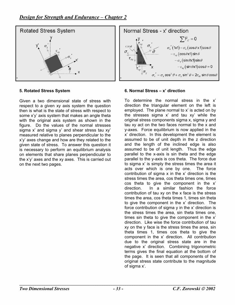
5. Rotated Stress System Given a two dimensional state of stress with respect to a given xy axis system the question then is what is the state of stress with respect to some x’y’ axis system that makes an angle theta with the original axis system as shown in the figure. Do the values of the normal stresses sigma x’ and sigma y’ and shear stress tau xy’ measured relative to planes perpendicular to the x’y’ axes change and how are they related to the given state of stress. To answer this question it is necessary to perform an equilibrium analysis on elements that share planes perpendicular to the x’y’ axes and the xy axes. This is carried out on the next two pages.
6. Normal Stress – x’ direction To determine the normal stress in the x’ direction the triangular element on the left is employed. The plane normal to x’ is acted on by the stresses sigma x’ and tau xy’ while the original stress components sigma x, sigma y and tau xy act on the two faces normal to the x and y-axes. Force equilibrium is now applied in the x’ direction. In this development the element is assumed to be of unit depth in the z direction and the length of the inclined edge is also assumed to be of unit length. Thus the edge parallel to the x-axis is sin theta and the edge parallel to the y-axis is cos theta. The force due to sigma x’ is simply the stress times the area it acts over which is one by one. The force contribution of sigma x in the x’ direction is the stress times the area, cos theta times one, times cos theta to give the component in the x’ direction. In a similar fashion the force contribution of tau xy on the x face is the stress times the area, cos theta times 1, times sin theta to give the component in the x’ direction. The force contribution of sigma y in the x’ direction is the stress times the area, sin theta times one, times sin theta to give the component in the x’ direction. Like wise the force contribution of tau xy on the y face is the stress times the area, sin theta times 1, times cos theta to give the component in the x’ direction. All contribution due to the original stress state are in the negative x’ direction. Combining trigonometric terms gives the final equation at the bottom of the page. It is seen that all components of the original stress state contribute to the magnitude of sigma x’.
Design for Strength and Endurance – Chapter 2
_____________________________________________________________________________________Two Dimensional Stresses - 34 - C.F. Zorowski 2002
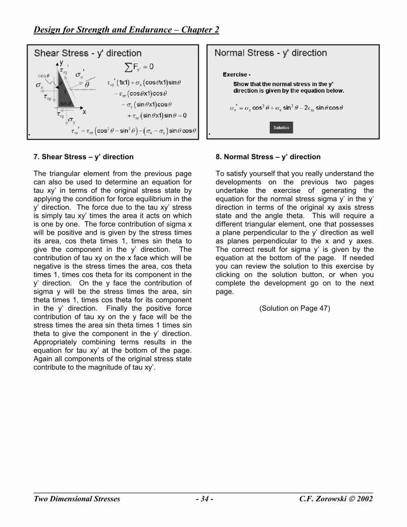
7. Shear Stress – y’ direction The triangular element from the previous page can also be used to determine an equation for tau xy’ in terms of the original stress state by applying the condition for force equilibrium in the y’ direction. The force due to the tau xy’ stress is simply tau xy’ times the area it acts on which is one by one. The force contribution of sigma x will be positive and is given by the stress times its area, cos theta times 1, times sin theta to give the component in the y’ direction. The contribution of tau xy on the x face which will be negative is the stress times the area, cos theta times 1, times cos theta for its component in the y’ direction. On the y face the contribution of sigma y will be the stress times the area, sin theta times 1, times cos theta for its component in the y’ direction. Finally the positive force contribution of tau xy on the y face will be the stress times the area sin theta times 1 times sin theta to give the component in the y’ direction. Appropriately combining terms results in the equation for tau xy’ at the bottom of the page. Again all components of the original stress state contribute to the magnitude of tau xy’.
8. Normal Stress – y’ direction To satisfy yourself that you really understand the developments on the previous two pages undertake the exercise of generating the equation for the normal stress sigma y’ in the y’ direction in terms of the original xy axis stress state and the angle theta. This will require a different triangular element, one that possesses a plane perpendicular to the y’ direction as well as planes perpendicular to the x and y axes. The correct result for sigma y’ is given by the equation at the bottom of the page. If needed you can review the solution to this exercise by clicking on the solution button, or when you complete the development go on to the next page.
(Solution on Page 47)
Design for Strength and Endurance – Chapter 2
_____________________________________________________________________________________Two Dimensional Stresses - 35 - C.F. Zorowski 2002
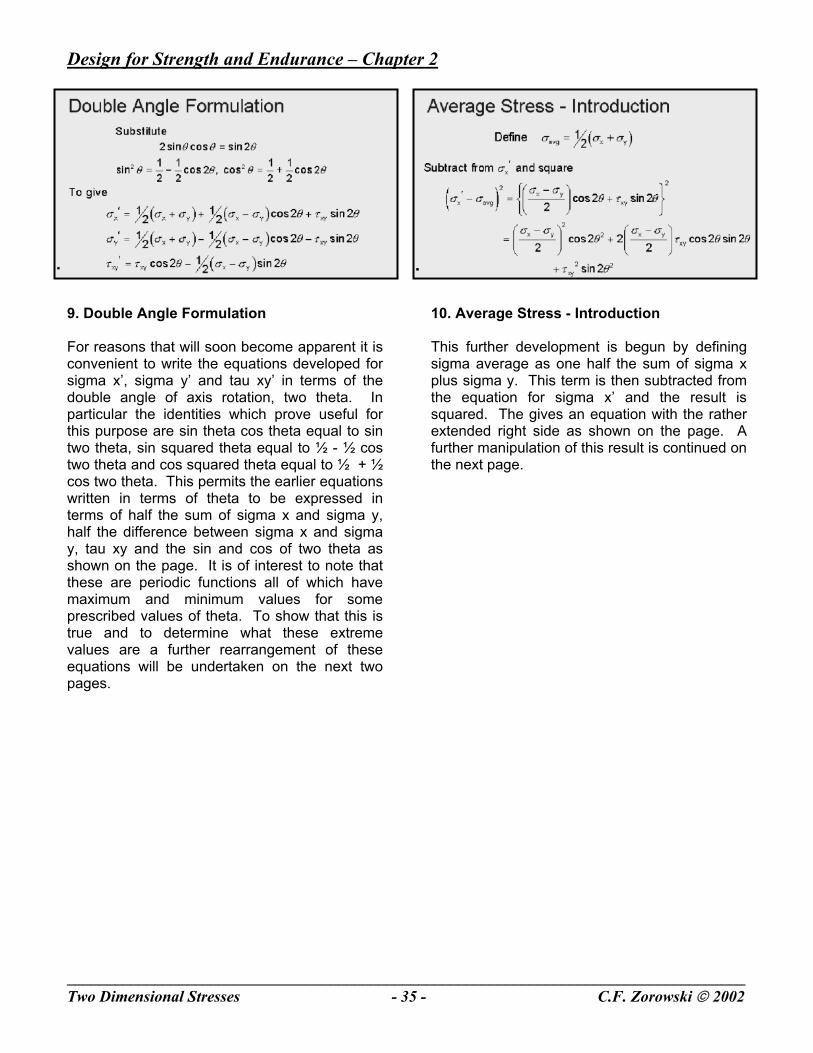
9. Double Angle Formulation For reasons that will soon become apparent it is convenient to write the equations developed for sigma x’, sigma y’ and tau xy’ in terms of the double angle of axis rotation, two theta. In particular the identities which prove useful for this purpose are sin theta cos theta equal to sin two theta, sin squared theta equal to ½ - ½ cos two theta and cos squared theta equal to ½ + ½ cos two theta. This permits the earlier equations written in terms of theta to be expressed in terms of half the sum of sigma x and sigma y, half the difference between sigma x and sigma y, tau xy and the sin and cos of two theta as shown on the page. It is of interest to note that these are periodic functions all of which have maximum and minimum values for some prescribed values of theta. To show that this is true and to determine what these extreme values are a further rearrangement of these equations will be undertaken on the next two pages.
10. Average Stress - Introduction This further development is begun by defining sigma average as one half the sum of sigma x plus sigma y. This term is then subtracted from the equation for sigma x’ and the result is squared. The gives an equation with the rather extended right side as shown on the page. A further manipulation of this result is continued on the next page.
Design for Strength and Endurance – Chapter 2
_____________________________________________________________________________________Two Dimensional Stresses - 36 - C.F. Zorowski 2002
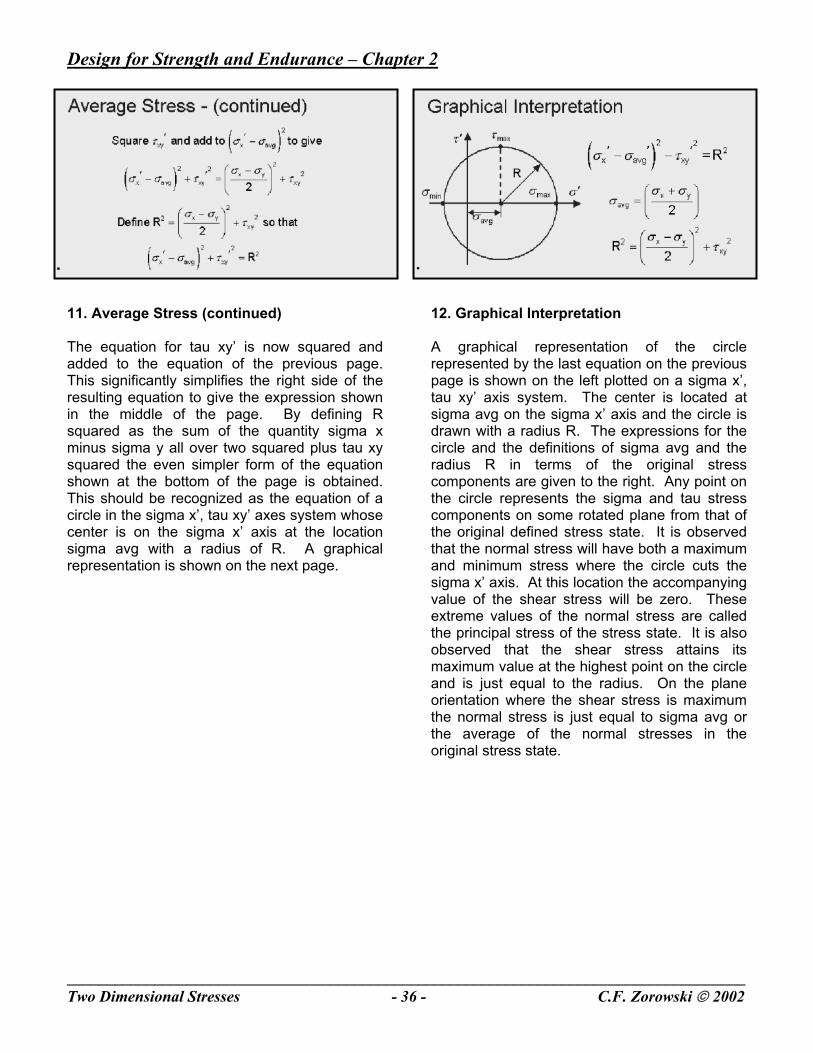
11. Average Stress (continued) The equation for tau xy’ is now squared and added to the equation of the previous page. This significantly simplifies the right side of the resulting equation to give the expression shown in the middle of the page. By defining R squared as the sum of the quantity sigma x minus sigma y all over two squared plus tau xy squared the even simpler form of the equation shown at the bottom of the page is obtained. This should be recognized as the equation of a circle in the sigma x’, tau xy’ axes system whose center is on the sigma x’ axis at the location sigma avg with a radius of R. A graphical representation is shown on the next page.
12. Graphical Interpretation A graphical representation of the circle represented by the last equation on the previous page is shown on the left plotted on a sigma x’, tau xy’ axis system. The center is located at sigma avg on the sigma x’ axis and the circle is drawn with a radius R. The expressions for the circle and the definitions of sigma avg and the radius R in terms of the original stress components are given to the right. Any point on the circle represents the sigma and tau stress components on some rotated plane from that of the original defined stress state. It is observed that the normal stress will have both a maximum and minimum stress where the circle cuts the sigma x’ axis. At this location the accompanying value of the shear stress will be zero. These extreme values of the normal stress are called the principal stress of the stress state. It is also observed that the shear stress attains its maximum value at the highest point on the circle and is just equal to the radius. On the plane orientation where the shear stress is maximum the normal stress is just equal to sigma avg or the average of the normal stresses in the original stress state.
Design for Strength and Endurance – Chapter 2
_____________________________________________________________________________________Two Dimensional Stresses - 37 - C.F. Zorowski 2002
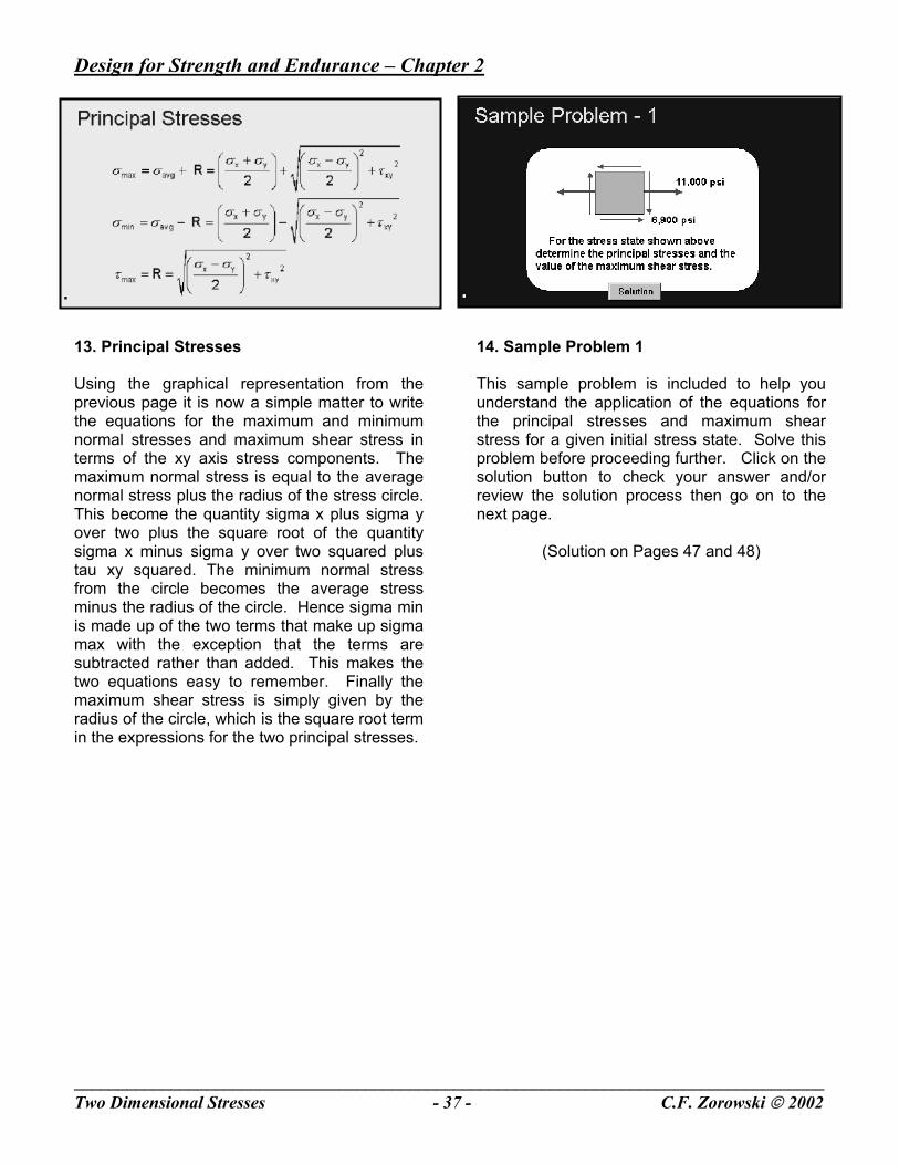
13. Principal Stresses Using the graphical representation from the previous page it is now a simple matter to write the equations for the maximum and minimum normal stresses and maximum shear stress in terms of the xy axis stress components. The maximum normal stress is equal to the average normal stress plus the radius of the stress circle. This become the quantity sigma x plus sigma y over two plus the square root of the quantity sigma x minus sigma y over two squared plus tau xy squared. The minimum normal stress from the circle becomes the average stress minus the radius of the circle. Hence sigma min is made up of the two terms that make up sigma max with the exception that the terms are subtracted rather than added. This makes the two equations easy to remember. Finally the maximum shear stress is simply given by the radius of the circle, which is the square root term in the expressions for the two principal stresses.
14. Sample Problem 1 This sample problem is included to help you understand the application of the equations for the principal stresses and maximum shear stress for a given initial stress state. Solve this problem before proceeding further. Click on the solution button to check your answer and/or review the solution process then go on to the next page.
(Solution on Pages 47 and 48)

Design for Strength and Endurance – Chapter 2
_____________________________________________________________________________________Two Dimensional Stresses - 38 - C.F. Zorowski 2002
15. Mohr circle construction The circular representation of the general two dimensional stress equations can also be used to determine the stress state on any set of rotated axes relative to the axis system of the original stress state. This construction is well known as Mohr’s circle, named after its developer. The question to be answered is: given a set of two dimensional stresses relative to an xy axis system as shown on the left what will be the normal and shear stress on a plane perpendicular to an x’ axis rotated through an angle theta in the counter clockwise direction. The graphical construction will take place on the sigma’ - tau’ coordinate system shown on the right. A point whose coordinates are sigma x and tau xy is plotted together with a second point whose coordinates are sigma y and minus tau xy in this axis field. A straight line is then drawn connecting these two points. This line is the diameter of the stress circle. Where it crosses the sigma ‘ axis is the center of the
circle. A circle defined in this fashion is now drawn. Next, an angle two theta is measured counterclockwise from the radius defined by point sigma x, tau xy. At this angular position another diameter is drawn on the circle. The point of intersection of the diameter with the circle represents the coordinates sigma x’ and tau xy’ the two desired stress on the plane perpendicular to the x’ direction. The point where the far end of this second diameter intersects the circle represents the coordinates sigma y’ and minus tau xy’ acting on a plane perpendicular to the y’ direction. It is further observed that the angle two theta between the planes on which the principal stress act and the maximum shear stresses act is 90 degrees. This means the physical planes on which these two sets of stresses act are at 45 degrees with respect to each other.
Design for Strength and Endurance – Chapter 2
_____________________________________________________________________________________Two Dimensional Stresses - 39 - C.F. Zorowski 2002
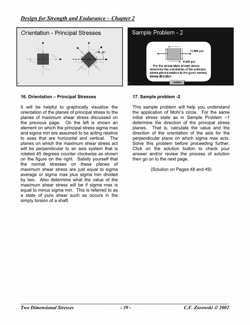
16. Orientation – Principal Stresses It will be helpful to graphically visualize the orientation of the planes of principal stress to the planes of maximum shear stress discussed on the previous page. On the left is shown an element on which the principal stress sigma max and sigma min are assumed to be acting relative to axes that are horizontal and vertical. The planes on which the maximum shear stress act will be perpendicular to an axis system that is rotated 45 degrees counter clockwise as shown on the figure on the right. Satisfy yourself that the normal stresses on these planes of maximum shear stress are just equal to sigma average or sigma max plus sigma min divided by two. Also determine what the value of the maximum shear stress will be if sigma max is equal to minus sigma min. This is referred to as a state of pure shear such as occurs in the simply torsion of a shaft.
17. Sample problem -2 This sample problem will help you understand the application of Mohr’s circle. For the same initial stress state as in Sample Problem –1 determine the direction of the principal stress planes. That is, calculate the value and the direction of the orientation of the axis for the perpendicular plane on which sigma max acts. Solve this problem before proceeding further. Click on the solution button to check your answer and/or review the process of solution then go on to the next page.
(Solution on Pages 48 and 49)
Design for Strength and Endurance – Chapter 2
_____________________________________________________________________________________Two Dimensional Stresses - 40 - C.F. Zorowski 2002
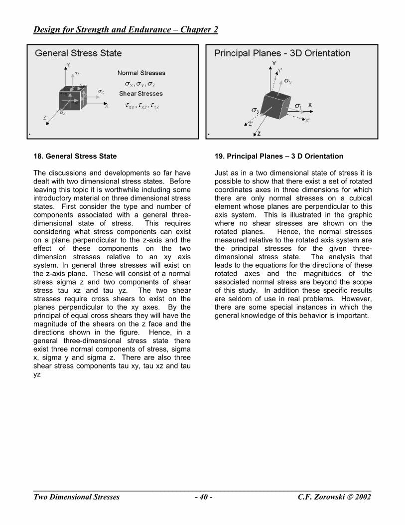
18. General Stress State The discussions and developments so far have dealt with two dimensional stress states. Before leaving this topic it is worthwhile including some introductory material on three dimensional stress states. First consider the type and number of components associated with a general three-dimensional state of stress. This requires considering what stress components can exist on a plane perpendicular to the z-axis and the effect of these components on the two dimension stresses relative to an xy axis system. In general three stresses will exist on the z-axis plane. These will consist of a normal stress sigma z and two components of shear stress tau xz and tau yz. The two shear stresses require cross shears to exist on the planes perpendicular to the xy axes. By the principal of equal cross shears they will have the magnitude of the shears on the z face and the directions shown in the figure. Hence, in a general three-dimensional stress state there exist three normal components of stress, sigma x, sigma y and sigma z. There are also three shear stress components tau xy, tau xz and tau yz
19. Principal Planes – 3 D Orientation Just as in a two dimensional state of stress it is possible to show that there exist a set of rotated coordinates axes in three dimensions for which there are only normal stresses on a cubical element whose planes are perpendicular to this axis system. This is illustrated in the graphic where no shear stresses are shown on the rotated planes. Hence, the normal stresses measured relative to the rotated axis system are the principal stresses for the given three-dimensional stress state. The analysis that leads to the equations for the directions of these rotated axes and the magnitudes of the associated normal stress are beyond the scope of this study. In addition these specific results are seldom of use in real problems. However, there are some special instances in which the general knowledge of this behavior is important.
Design for Strength and Endurance – Chapter 2
_____________________________________________________________________________________Two Dimensional Stresses - 41 - C.F. Zorowski 2002
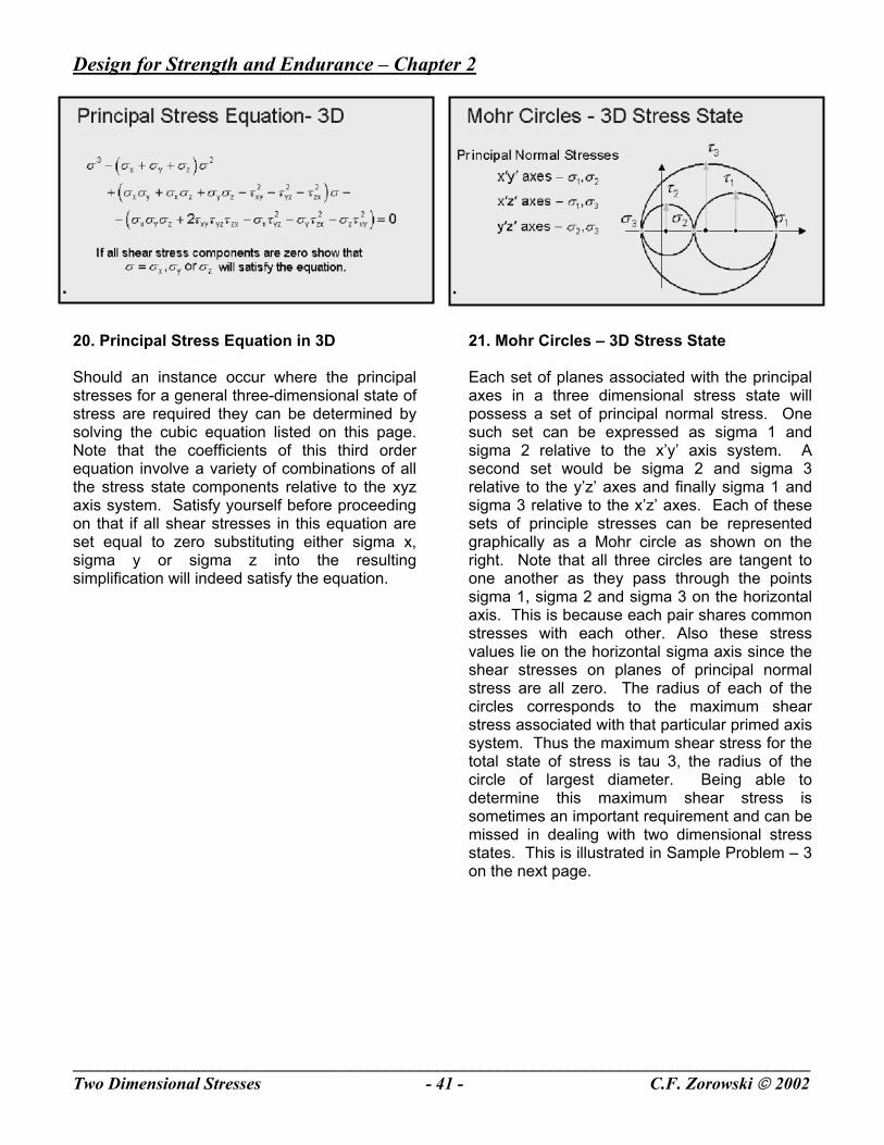
20. Principal Stress Equation in 3D Should an instance occur where the principal stresses for a general three-dimensional state of stress are required they can be determined by solving the cubic equation listed on this page. Note that the coefficients of this third order equation involve a variety of combinations of all the stress state components relative to the xyz axis system. Satisfy yourself before proceeding on that if all shear stresses in this equation are set equal to zero substituting either sigma x, sigma y or sigma z into the resulting simplification will indeed satisfy the equation.
21. Mohr Circles – 3D Stress State Each set of planes associated with the principal axes in a three dimensional stress state will possess a set of principal normal stress. One such set can be expressed as sigma 1 and sigma 2 relative to the x’y’ axis system. A second set would be sigma 2 and sigma 3 relative to the y’z’ axes and finally sigma 1 and sigma 3 relative to the x’z’ axes. Each of these sets of principle stresses can be represented graphically as a Mohr circle as shown on the right. Note that all three circles are tangent to one another as they pass through the points sigma 1, sigma 2 and sigma 3 on the horizontal axis. This is because each pair shares common stresses with each other. Also these stress values lie on the horizontal sigma axis since the shear stresses on planes of principal normal stress are all zero. The radius of each of the circles corresponds to the maximum shear stress associated with that particular primed axis system. Thus the maximum shear stress for the total state of stress is tau 3, the radius of the circle of largest diameter. Being able to determine this maximum shear stress is sometimes an important requirement and can be missed in dealing with two dimensional stress states. This is illustrated in Sample Problem – 3 on the next page.
Design for Strength and Endurance – Chapter 2
_____________________________________________________________________________________Two Dimensional Stresses - 42 - C.F. Zorowski 2002
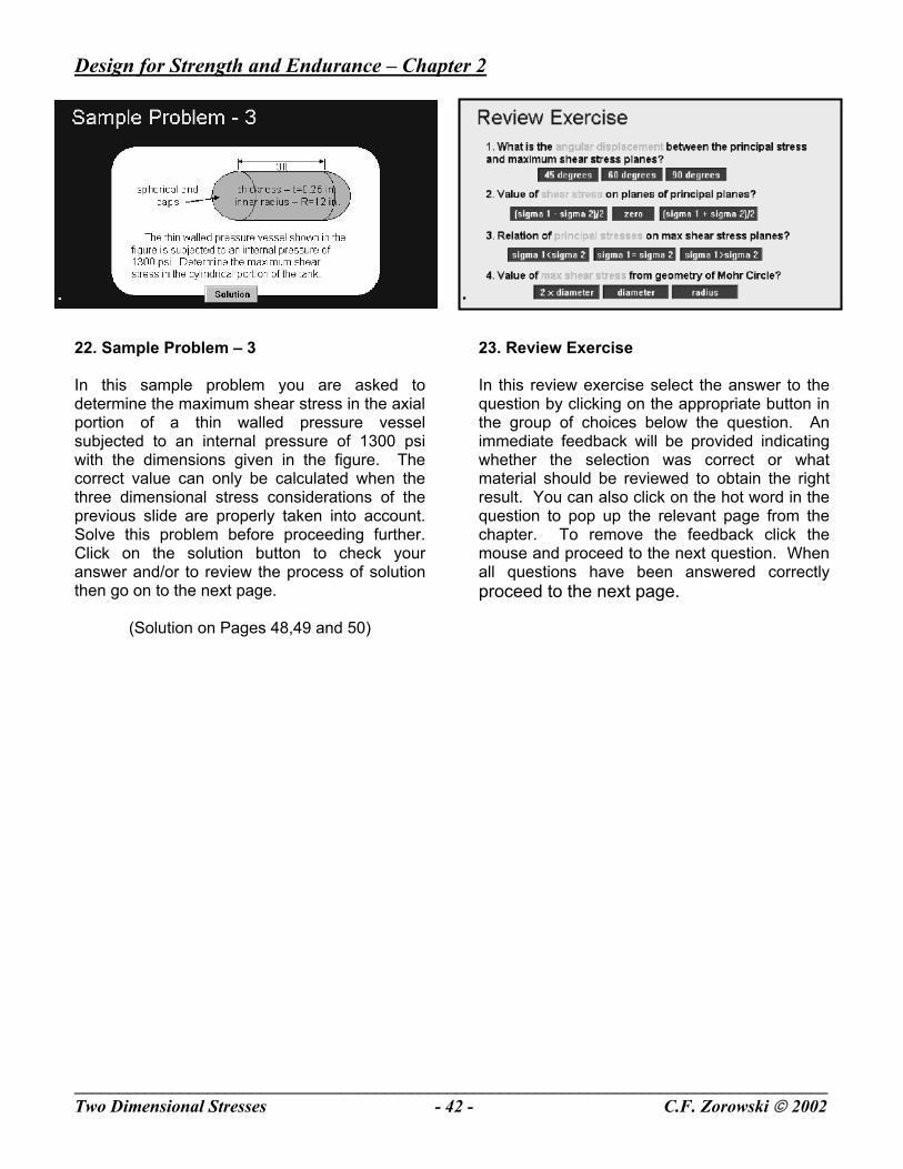
22. Sample Problem – 3 In this sample problem you are asked to determine the maximum shear stress in the axial portion of a thin walled pressure vessel subjected to an internal pressure of 1300 psi with the dimensions given in the figure. The correct value can only be calculated when the three dimensional stress considerations of the previous slide are properly taken into account. Solve this problem before proceeding further. Click on the solution button to check your answer and/or to review the process of solution then go on to the next page.
(Solution on Pages 48,49 and 50)
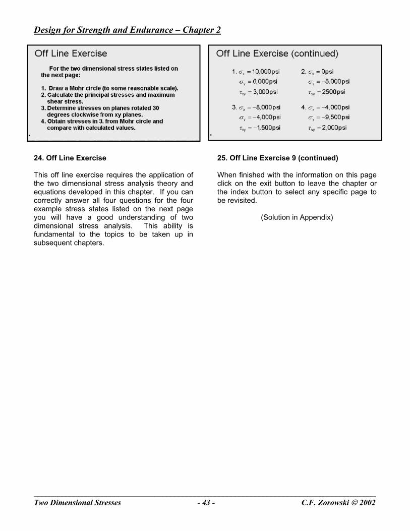
23. Review Exercise In this review exercise select the answer to the question by clicking on the appropriate button in the group of choices below the question. An immediate feedback will be provided indicating whether the selection was correct or what material should be reviewed to obtain the right result. You can also click on the hot word in the question to pop up the relevant page from the chapter. To remove the feedback click the mouse and proceed to the next question. When all questions have been answered correctly proceed to the next page.
Design for Strength and Endurance – Chapter 2
_____________________________________________________________________________________Two Dimensional Stresses - 43 - C.F. Zorowski 2002
24. Off Line Exercise This off line exercise requires the application of the two dimensional stress analysis theory and equations developed in this chapter. If you can correctly answer all four questions for the four example stress states listed on the next page you will have a good understanding of two dimensional stress analysis. This ability is fundamental to the topics to be taken up in subsequent chapters.
25. Off Line Exercise 9 (continued) When finished with the information on this page click on the exit button to leave the chapter or the index button to select any specific page to be revisited.
(Solution in Appendix)

Design for Strength and Endurance – Chapter 2
_____________________________________________________________________________________Two Dimensional Stresses - 44 - C.F. Zorowski 2002
Design for Strength and Endurance – Chapter 2
_____________________________________________________________________________________Two Dimensional Stresses - 45 - C.F. Zorowski 2002
Chapter 2 Two Dimensional Stress Analysis
Problem Solutions
Screen Titles
Normal Stress - Y’ direction Maximum Normal Stress Minimum Normal Stress / Shear Stress Generic Principal Axis Formula Principal Axis Orientation Axial Stress Hoop Stress Stress Calculations Complete Stress State Maximum Shear Stress

Design for Strength and Endurance – Chapter 2
_____________________________________________________________________________________Two Dimensional Stresses - 46 - C.F. Zorowski 2002

Design for Strength and Endurance – Chapter 2
_____________________________________________________________________________________Two Dimensional Stresses - 47 - C.F. Zorowski 2002
1. Normal Stress - y’ direction The element shown on the left is chosen to determine the normal stress in the y’ direction since it contains planes perpendicular to the x, y and y’ axes. Again force equilibrium is applied in the y’ direction taking into account the contributions of all the stress components acting on the element. First recognize that if the length of the inclined edge of the element is taken to be unity then the length of the edge parallel to the x axis is cos theta and the edge parallel to the y axis is sin theta. It is also assumed that the element is of unit depth in the z direction. To apply equilibrium all stress components must be multiplied by the area over which they act before being multiplied by the appropriate trigonometric function of theta to give their contibution in the y’ direction. The force contribution of sigma y’ is simply the stress times the area one time one. On the x face sigma x has a negative contribution equal to the stress times the area sin theta times one times the sin of theta. The positive force contribution of tau xy on the x face is the stress times the area times cos theta. On the y face the negative force contribution of sigma y in the y’ direction is the stress times the area cos theta time one times cos theta. Tau xy on the y face contributes a positive force contribution in the y’ direction equal to the stress times the area times sin theta. Carrying through the multiplication, combining the tau xy terms and solving for sigma y’ gives the equation at the bottom of the page.
2. Maximum Normal Stress Begin with the equation for the maximum normal stress, sigma 1, that is the sum of sigma average, the quantity sigma x plus sigma y divided by two, plus the radius of the stress circle, the square root of the quantity sigma x minus sigma y over 2 squared plus tau xy squared. Next substitute the values of the given stress state for the parameters into the equation. These are sigma x equal to 11,000 psi, sigma y equal to zero and tau xy equal to 6,900 psi. Carrying out the indicated mathematical operations gives a final answer for sigma 1, the maximum normal stress, of 14,320 psi. tension.
Design for Strength and Endurance – Chapter 2
_____________________________________________________________________________________Two Dimensional Stresses - 48 - C.F. Zorowski 2002
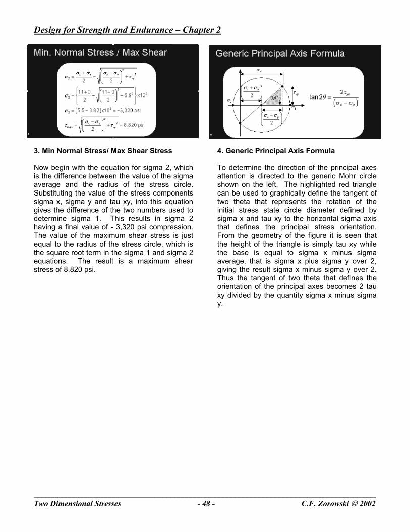
3. Min Normal Stress/ Max Shear Stress Now begin with the equation for sigma 2, which is the difference between the value of the sigma average and the radius of the stress circle. Substituting the value of the stress components sigma x, sigma y and tau xy, into this equation gives the difference of the two numbers used to determine sigma 1. This results in sigma 2 having a final value of - 3,320 psi compression. The value of the maximum shear stress is just equal to the radius of the stress circle, which is the square root term in the sigma 1 and sigma 2 equations. The result is a maximum shear stress of 8,820 psi.
4. Generic Principal Axis Formula To determine the direction of the principal axes attention is directed to the generic Mohr circle shown on the left. The highlighted red triangle can be used to graphically define the tangent of two theta that represents the rotation of the initial stress state circle diameter defined by sigma x and tau xy to the horizontal sigma axis that defines the principal stress orientation. From the geometry of the figure it is seen that the height of the triangle is simply tau xy while the base is equal to sigma x minus sigma average, that is sigma x plus sigma y over 2, giving the result sigma x minus sigma y over 2. Thus the tangent of two theta that defines the orientation of the principal axes becomes 2 tau xy divided by the quantity sigma x minus sigma y.
Design for Strength and Endurance – Chapter 2
_____________________________________________________________________________________Two Dimensional Stresses - 49 - C.F. Zorowski 2002
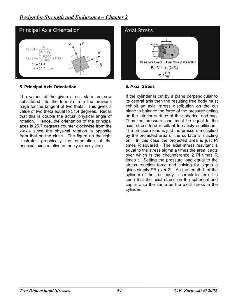
5. Principal Axis Orientation The values of the given stress state are now substituted into the formula from the previous page for the tangent of two theta. This gives a value of two theta equal to 51.4 degrees. Recall that this is double the actual physical angle of rotation. Hence, the orientation of the principal axes is 25.7 degrees counter clockwise from the x-axis since the physical rotation is opposite from that on the circle. The figure on the right illustrates graphically the orientation of the principal axes relative to the xy axes system.
6. Axial Stress If the cylinder is cut by a plane perpendicular to its central axis then the resulting free body must exhibit an axial stress distribution on the cut plane to balance the force of the pressure acting on the interior surface of the spherical end cap. Thus the pressure load must be equal to the axial stress load resultant to satisfy equilibrium. The pressure load is just the pressure multiplied by the projected area of the surface it is acting on. In this case the projected area is just Pi times R squared. The axial stress resultant is equal to the stress sigma a times the area it acts over which is the circumference 2 Pi times R times t. Setting the pressure load equal to the stress reaction force and solving for sigma a gives simply PR over 2t. As the length L of the cylinder of the free body is shrunk to zero it is seen that the axial stress on the spherical end cap is also the same as the axial stress in the cylinder.
Design for Strength and Endurance – Chapter 2
_____________________________________________________________________________________Two Dimensional Stresses - 50 - C.F. Zorowski 2002
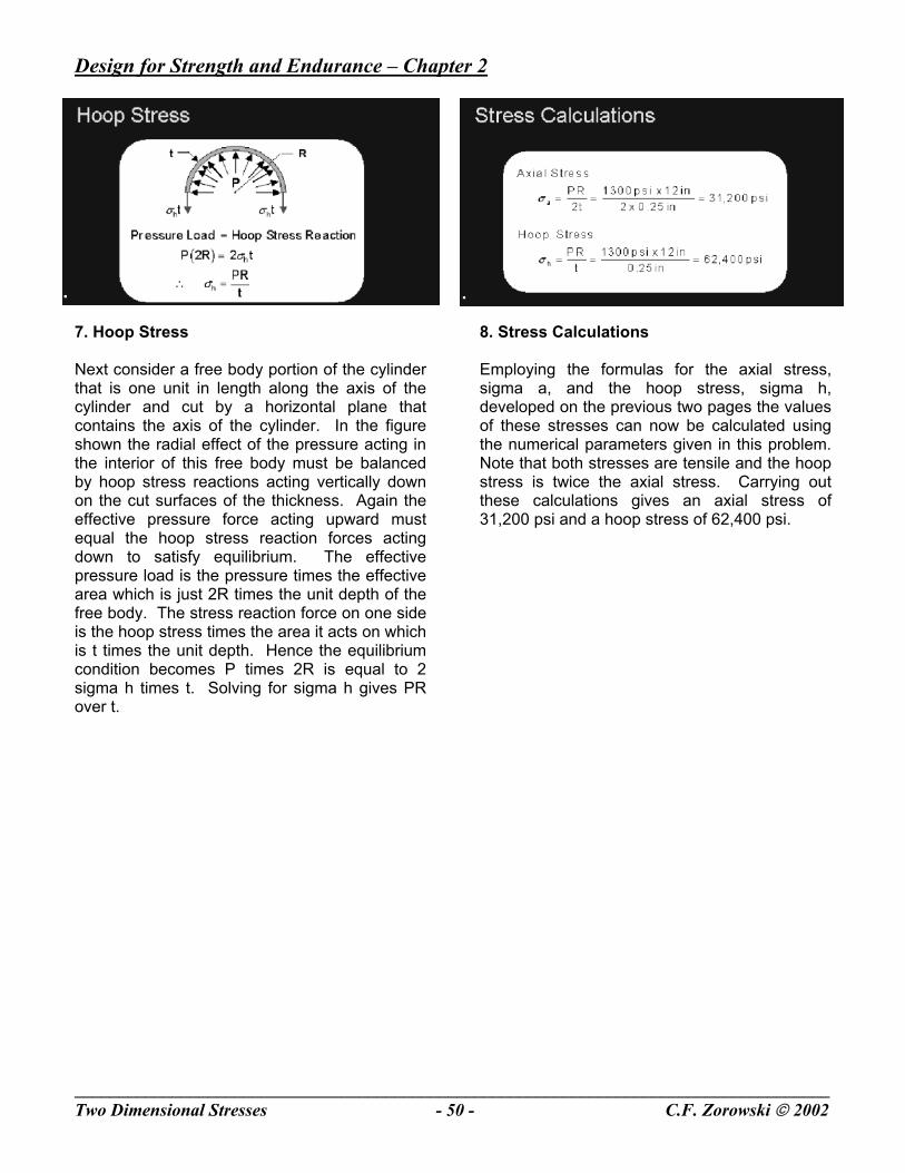
7. Hoop Stress Next consider a free body portion of the cylinder that is one unit in length along the axis of the cylinder and cut by a horizontal plane that contains the axis of the cylinder. In the figure shown the radial effect of the pressure acting in the interior of this free body must be balanced by hoop stress reactions acting vertically down on the cut surfaces of the thickness. Again the effective pressure force acting upward must equal the hoop stress reaction forces acting down to satisfy equilibrium. The effective pressure load is the pressure times the effective area which is just 2R times the unit depth of the free body. The stress reaction force on one side is the hoop stress times the area it acts on which is t times the unit depth. Hence the equilibrium condition becomes P times 2R is equal to 2 sigma h times t. Solving for sigma h gives PR over t.
8. Stress Calculations Employing the formulas for the axial stress, sigma a, and the hoop stress, sigma h, developed on the previous two pages the values of these stresses can now be calculated using the numerical parameters given in this problem. Note that both stresses are tensile and the hoop stress is twice the axial stress. Carrying out these calculations gives an axial stress of 31,200 psi and a hoop stress of 62,400 psi.
Design for Strength and Endurance – Chapter 2
_____________________________________________________________________________________Two Dimensional Stresses - 51 - C.F. Zorowski 2002
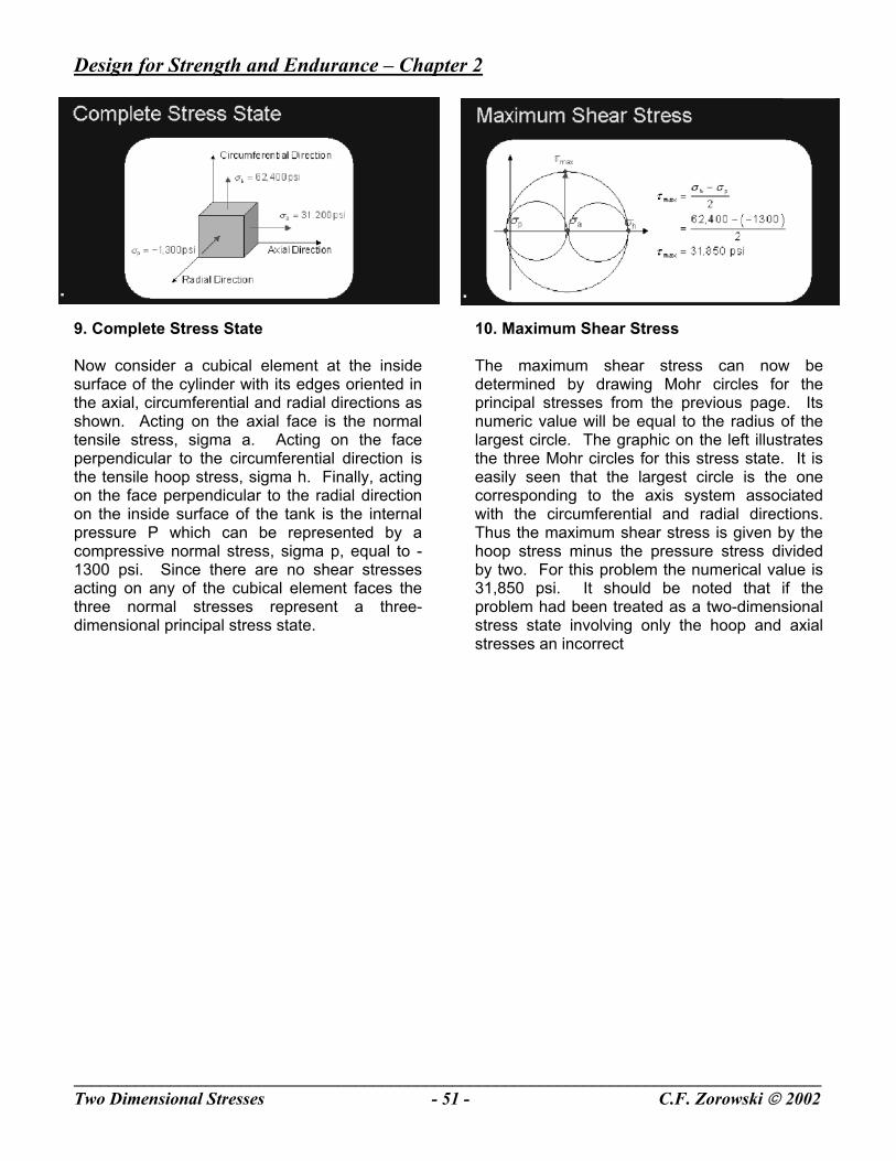
9. Complete Stress State Now consider a cubical element at the inside surface of the cylinder with its edges oriented in the axial, circumferential and radial directions as shown. Acting on the axial face is the normal tensile stress, sigma a. Acting on the face perpendicular to the circumferential direction is the tensile hoop stress, sigma h. Finally, acting on the face perpendicular to the radial direction on the inside surface of the tank is the internal pressure P which can be represented by a compressive normal stress, sigma p, equal to -1300 psi. Since there are no shear stresses acting on any of the cubical element faces the three normal stresses represent a three-dimensional principal stress state.
10. Maximum Shear Stress The maximum shear stress can now be determined by drawing Mohr circles for the principal stresses from the previous page. Its numeric value will be equal to the radius of the largest circle. The graphic on the left illustrates the three Mohr circles for this stress state. It is easily seen that the largest circle is the one corresponding to the axis system associated with the circumferential and radial directions. Thus the maximum shear stress is given by the hoop stress minus the pressure stress divided by two. For this problem the numerical value is 31,850 psi. It should be noted that if the problem had been treated as a two-dimensional stress state involving only the hoop and axial stresses an incorrect
Design for Strength and Endurance – Chapter 2
_____________________________________________________________________________________Two Dimensional Stresses - 52 - C.F. Zorowski 2002
Related Documents