Chapter 2 – Combinational Logic Circuits Part 1 – Gate Circuits and Boolean Equations Logic and Computer Design Fundamentals

Welcome message from author
This document is posted to help you gain knowledge. Please leave a comment to let me know what you think about it! Share it to your friends and learn new things together.
Transcript

Chapter 2 – Combinational Logic Circuits
Part 1 – Gate Circuits and Boolean Equations
Logic and Computer Design Fundamentals
Chapter 2 - Part 1 2
Overview
Part 1 – Gate Circuits and Boolean Equations• Binary Logic and Gates• Boolean Algebra• Standard Forms
Part 2 – Circuit Optimization• Two-Level Optimization• Map Manipulation• Practical Optimization (Espresso)• Multi-Level Circuit Optimization
Part 3 – Additional Gates and Circuits• Other Gate Types• Exclusive-OR Operator and Gates• High-Impedance Outputs
Chapter 2 - Part 1 3
Binary Logic and Gates
Binary variables take on one of two values. Logical operators operate on binary values and
binary variables. Basic logical operators are the logic functions
AND, OR and NOT. Logic gates implement logic functions. Boolean Algebra: a useful mathematical system
for specifying and transforming logic functions. We study Boolean algebra as a foundation for
designing and analyzing digital systems!
Chapter 2 - Part 1 4
Binary Variables Recall that the two binary values have
different names:• True/False• On/Off• Yes/No• 1/0
We use 1 and 0 to denote the two values. Variable identifier examples:
• A, B, y, z, or X1 for now• RESET, START_IT, or ADD1 later
Chapter 2 - Part 1 5
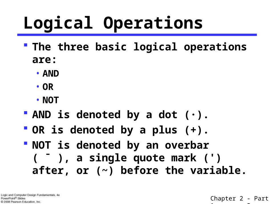
Logical Operations The three basic logical operations are:
• AND • OR• NOT
AND is denoted by a dot (·). OR is denoted by a plus (+). NOT is denoted by an overbar ( ¯ ), a
single quote mark (') after, or (~) before the variable.

Chapter 2 - Part 1 6
Examples:• is read “Y is equal to A AND B.”• is read “z is equal to x OR y.”• is read “X is equal to NOT A.”
Notation Examples
Note: The statement: 1 + 1 = 2 (read “one plus one equals two”)
is not the same as1 + 1 = 1 (read “1 or 1 equals 1”).
BAY yxz
AX

Chapter 2 - Part 1 7
Operator Definitions
Operations are defined on the values "0" and "1" for each operator:
AND
0 · 0 = 00 · 1 = 01 · 0 = 01 · 1 = 1
OR
0 + 0 = 00 + 1 = 11 + 0 = 11 + 1 = 1
NOT
1001
Chapter 2 - Part 1 8
01
10
X
NOT
XZ
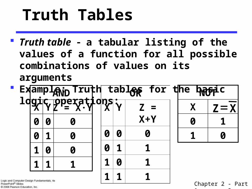
Truth Tables
Truth table a tabular listing of the values of a function for all possible combinations of values on its arguments
Example: Truth tables for the basic logic operations:
111
001
010
000
Z = X·YYX
AND OR
X Y Z = X+Y
0 0 0
0 1 1
1 0 1
1 1 1

Chapter 2 - Part 1 9
Using Switches• For inputs:
logic 1 is switch closed logic 0 is switch open
• For outputs: logic 1 is light on logic 0 is light off.
• NOT uses a switch such that:
logic 1 is switch open logic 0 is switch closed
Logic Function Implementation
Switches in series => AND
Switches in parallel => OR
CNormally-closed switch => NOT
Chapter 2 - Part 1 10
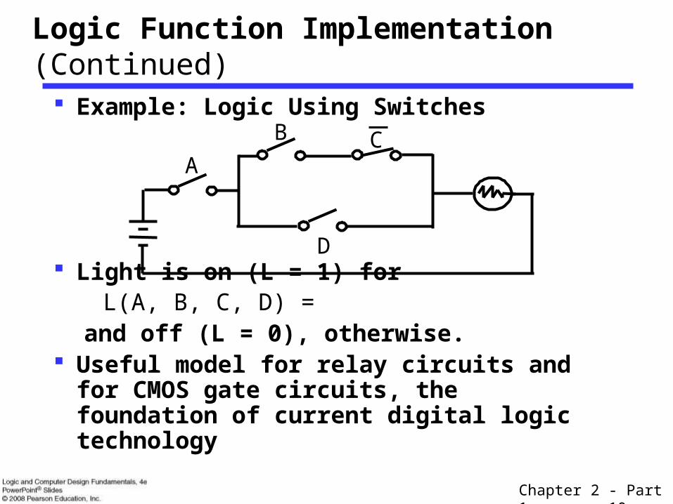
Example: Logic Using Switches
Light is on (L = 1) for L(A, B, C, D) =
and off (L = 0), otherwise. Useful model for relay circuits and for CMOS
gate circuits, the foundation of current digital logic technology
Logic Function Implementation (Continued)
B
A
D
C
Chapter 2 - Part 1 11
Logic Gates
In the earliest computers, switches were opened and closed by magnetic fields produced by energizing coils in relays. The switches in turn opened and closed the current paths.
Later, vacuum tubes that open and close current paths electronically replaced relays.
Today, transistors are used as electronic switches that open and close current paths.
Optional: Chapter 6 – Part 1: The Design Space
Chapter 2 - Part 1 12
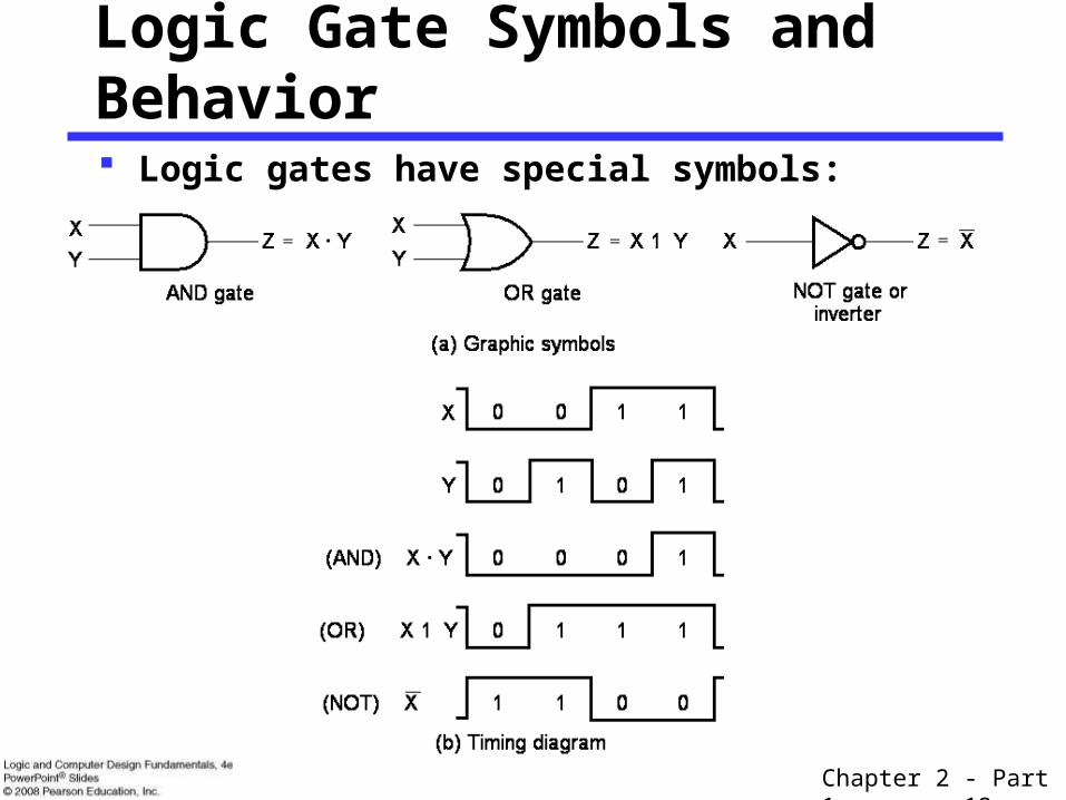
Logic Gate Symbols and Behavior
Logic gates have special symbols:

Chapter 2 - Part 1 13
Gate Delay
In actual physical gates, if one or more input changes causes the output to change, the output change does not occur instantaneously.
The delay between an input change(s) and the resulting output change is the gate delay denoted by tG:
tGtG
Input
Output
Time (ns)
0
0
1
1
0 0.5 1 1.5
tG = 0.3 ns

Chapter 2 - Part 1 14
Logic Diagrams and Expressions
Boolean equations, truth tables and logic diagrams describe the same function! Truth tables are unique; expressions and logic diagrams are not. This gives
flexibility in implementing functions.
X
Y F
Z
Logic Diagram
Equation
ZY X F
Truth Table
11 1 1
11 1 0
11 0 1
11 0 0
00 1 1
00 1 0
10 0 1
00 0 0
X Y Z Z Y X F
Chapter 2 - Part 1 15
1.
3.
5.
7.
9.
11.
13.
15.
17.
Commutative
Associative
Distributive
DeMorgan’s
2.
4.
6.
8.
X . 1 X=
X . 0 0=
X . X X=
0=X . X
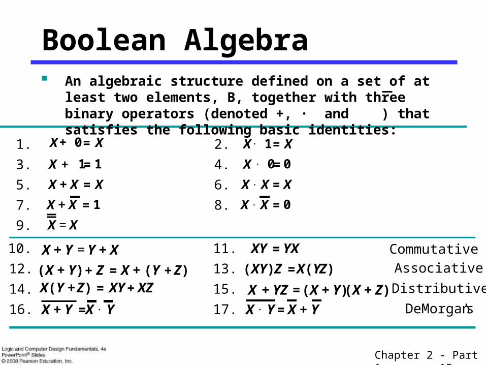
Boolean Algebra An algebraic structure defined on a set of at least two elements,
B, together with three binary operators (denoted +, · and ) that satisfies the following basic identities:
10.
12.
14.
16.
X + Y Y + X=
(X + Y) Z+ X + (Y Z)+=X(Y + Z) XY XZ+=
X + Y X . Y=
XY YX=
(XY) Z X(YZ)=
X + YZ (X + Y) (X + Z)=
X . Y X + Y=
X + 0 X=
+X 1 1=
X + X X=
1=X + X
X = X

Chapter 2 - Part 1 16
The identities above are organized into pairs. These pairs have names as follows:
1-4 Existence of 0 and 1 5-6 Idempotence
7-8 Existence of complement 9 Involution
10-11 Commutative Laws 12-13 Associative Laws
14-15 Distributive Laws 16-17 DeMorgan’s Laws
If the meaning is unambiguous, we leave out the symbol “·”
Some Properties of Identities & the Algebra
The dual of an algebraic expression is obtained by interchanging + and · and interchanging 0’s and 1’s.
The identities appear in dual pairs. When there is only one identity on a line the identity is self-dual, i. e., the dual expression = the original expression.

Chapter 2 - Part 1 17
Unless it happens to be self-dual, the dual of an expression does not equal the expression itself.
Example: F = (A + C) · B + 0
dual F = (A · C + B) · 1 = A · C + B Example: G = X · Y + (W + Z)
dual G = Example: H = A · B + A · C + B · C
dual H = Are any of these functions self-dual?
Some Properties of Identities & the Algebra (Continued)

Chapter 2 - Part 1 18
There can be more that 2 elements in B, i. e., elements other than 1 and 0. What are some common useful Boolean algebras with more than 2 elements?
1.
2.
If B contains only 1 and 0, then B is called the switching algebra which is the algebra we use most often.
Some Properties of Identities & the Algebra(Continued)
Algebra of Sets
Algebra of n-bit binary vectors

Chapter 2 - Part 1 19
Boolean Operator Precedence
The order of evaluation in a Boolean expression is:
1. Parentheses2. NOT3. AND4. OR
Consequence: Parentheses appear around OR expressions Example: F = A(B + C)(C + D)

Chapter 2 - Part 1 20
Example 1: Boolean Algebraic Proof
A + A·B = A (Absorption Theorem)Proof Steps Justification (identity or
theorem) A + A·B
= A · 1 + A · B X = X · 1 = A · ( 1 + B) X · Y + X · Z = X ·(Y + Z)(Distributive Law)
= A · 1 1 + X = 1
= A X · 1 = X
Our primary reason for doing proofs is to learn:• Careful and efficient use of the identities and theorems of
Boolean algebra, and• How to choose the appropriate identity or theorem to apply
to make forward progress, irrespective of the application.
Chapter 2 - Part 1 21
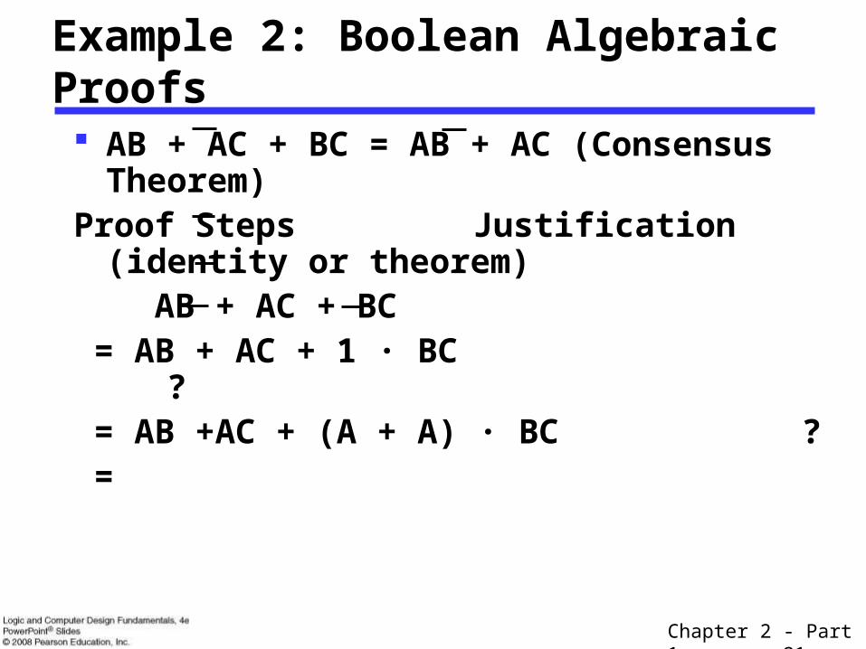
AB + AC + BC = AB + AC (Consensus Theorem)Proof Steps Justification (identity or
theorem) AB + AC + BC = AB + AC + 1 · BC ? = AB +AC + (A + A) · BC ? =
Example 2: Boolean Algebraic Proofs

Chapter 2 - Part 1 22
Example 3: Boolean Algebraic Proofs
Proof Steps Justification (identity or
theorem)
=
YXZ)YX(
)ZX(XZ)YX( Y Y

Chapter 2 - Part 1 23
x yy
Useful Theorems
ninimizatioMyyyxyyyx
tionSimplifica yxyxyxyx
Absorption xyxxxyxx
Consensuszyxzyzyx zyxzyzyx
Laws sDeMorgan'xx
x x
x x
x x
x x
y x y
Chapter 2 - Part 1 24
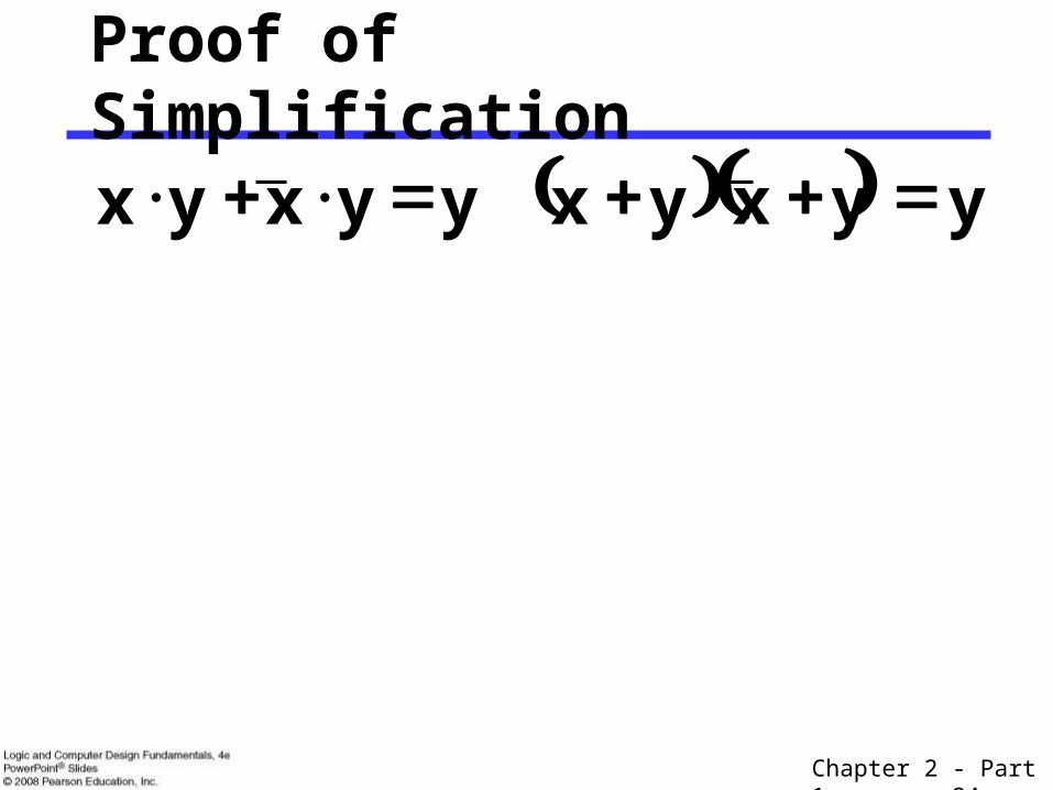
Proof of Simplification
yyyxyyyx x x

Chapter 2 - Part 1 25
Proof of DeMorgan’s Laws
yx x y yx yx
Chapter 2 - Part 1 26
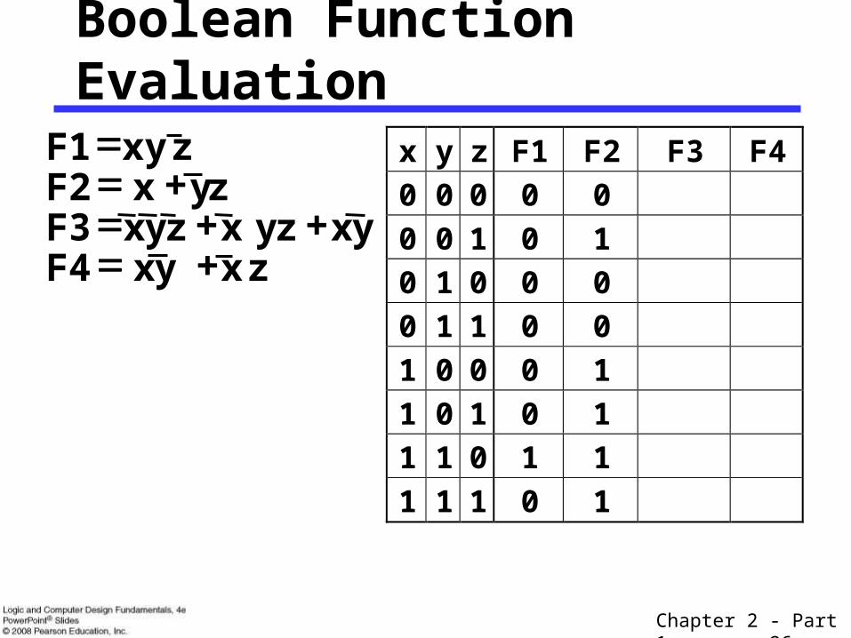
Boolean Function Evaluation
x y z F1 F2 F3 F4
0 0 0 0 0
0 0 1 0 1
0 1 0 0 0
0 1 1 0 0
1 0 0 0 1
1 0 1 0 1
1 1 0 1 1
1 1 1 0 1
z x yx F4x z yx zyx F3
x F2xy F1
z
yzy
Chapter 2 - Part 1 27
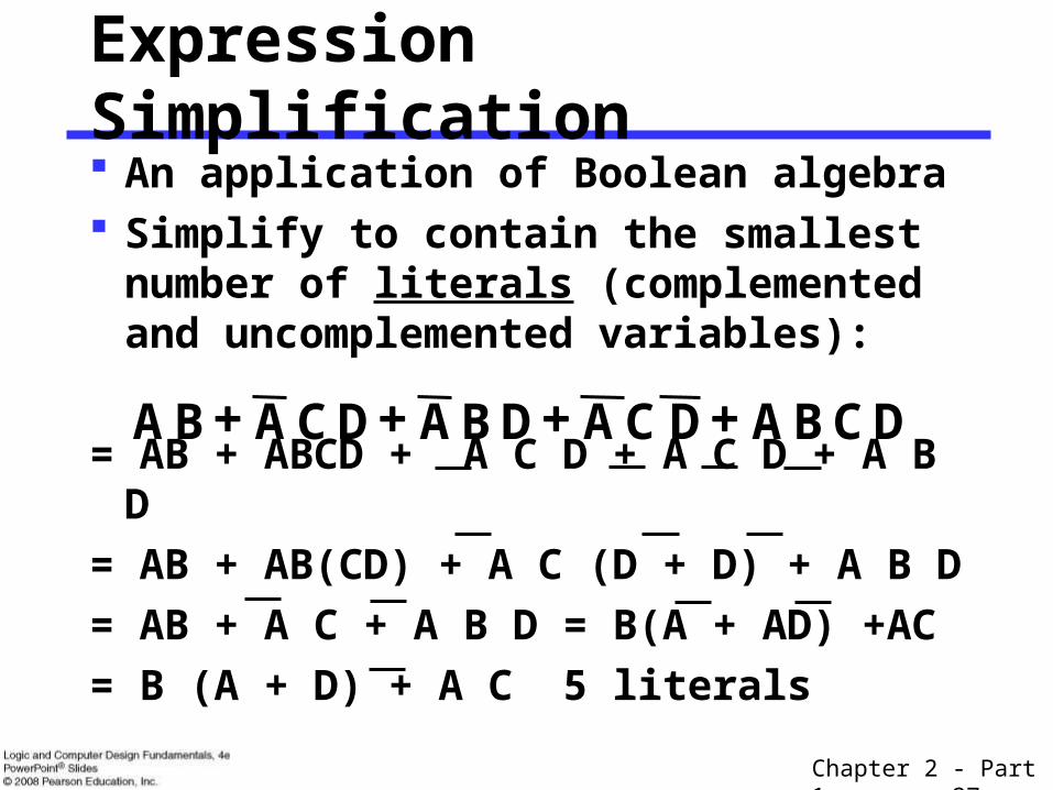
Expression Simplification An application of Boolean algebra Simplify to contain the smallest number
of literals (complemented and uncomplemented variables):
= AB + ABCD + A C D + A C D + A B D
= AB + AB(CD) + A C (D + D) + A B D
= AB + A C + A B D = B(A + AD) +AC
= B (A + D) + A C 5 literals
DCBADCADBADCABA
Chapter 2 - Part 1 28
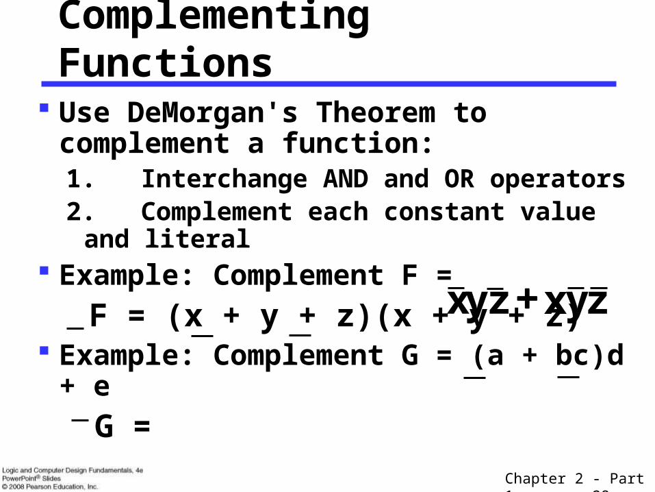
Complementing Functions
Use DeMorgan's Theorem to complement a function:1. Interchange AND and OR operators2. Complement each constant value and
literal Example: Complement F =
F = (x + y + z)(x + y + z) Example: Complement G = (a + bc)d + e
G =
x zyzyx

Chapter 2 - Part 1 29
Overview – Canonical Forms
What are Canonical Forms? Minterms and Maxterms Index Representation of Minterms and
Maxterms Sum-of-Minterm (SOM) Representations Product-of-Maxterm (POM) Representations Representation of Complements of Functions Conversions between Representations
Chapter 2 - Part 1 30
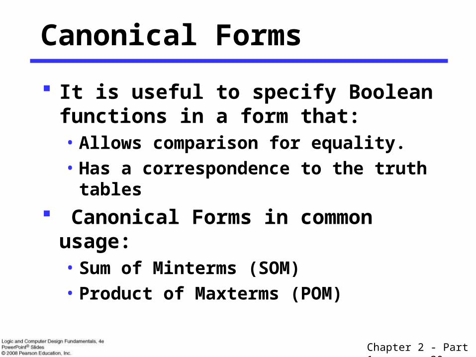
Canonical Forms
It is useful to specify Boolean functions in a form that:• Allows comparison for equality.• Has a correspondence to the truth tables
Canonical Forms in common usage:• Sum of Minterms (SOM)• Product of Maxterms (POM)
Chapter 2 - Part 1 31
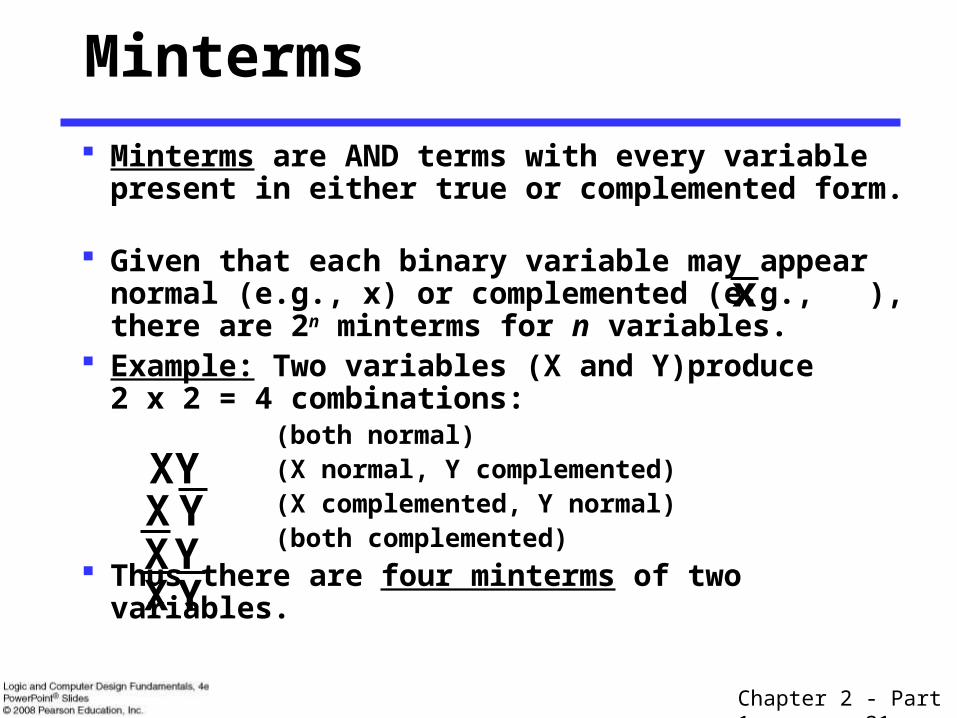
Minterms
Minterms are AND terms with every variable present in either true or complemented form.
Given that each binary variable may appear normal (e.g., x) or complemented (e.g., ), there are 2n minterms for n variables.
Example: Two variables (X and Y)produce2 x 2 = 4 combinations: (both normal) (X normal, Y complemented) (X complemented, Y normal) (both complemented)
Thus there are four minterms of two variables.
YXXY
YXYX
x
Chapter 2 - Part 1 32
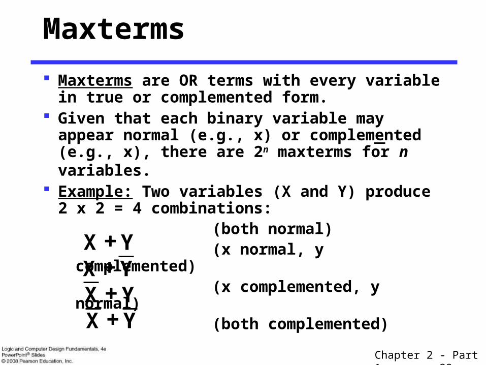
Maxterms
Maxterms are OR terms with every variable in true or complemented form.
Given that each binary variable may appear normal (e.g., x) or complemented (e.g., x), there are 2n maxterms for n variables.
Example: Two variables (X and Y) produce2 x 2 = 4 combinations: (both normal) (x normal, y complemented) (x complemented, y normal) (both complemented)
YX YX YX YX

Chapter 2 - Part 1 33
Examples: Two variable minterms and maxterms.
The index above is important for describing which variables in the terms are true and which are complemented.
Maxterms and Minterms
Index Minterm Maxterm
0 x y x + y
1 x y x + y
2 x y x + y
3 x y x + y

Chapter 2 - Part 1 34
Standard Order Minterms and maxterms are designated with a subscript The subscript is a number, corresponding to a binary pattern The bits in the pattern represent the complemented or normal
state of each variable listed in a standard order. All variables will be present in a minterm or maxterm and
will be listed in the same order (usually alphabetically) Example: For variables a, b, c:
• Maxterms: (a + b + c), (a + b + c)• Terms: (b + a + c), a c b, and (c + b + a) are NOT in
standard order.• Minterms: a b c, a b c, a b c• Terms: (a + c), b c, and (a + b) do not contain all
variables
Chapter 2 - Part 1 35
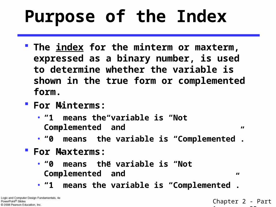
Purpose of the Index
The index for the minterm or maxterm, expressed as a binary number, is used to determine whether the variable is shown in the true form or complemented form.
For Minterms:• “1” means the variable is “Not Complemented” and
• “0” means the variable is “Complemented”.
For Maxterms:• “0” means the variable is “Not Complemented” and
• “1” means the variable is “Complemented”.
Chapter 2 - Part 1 36
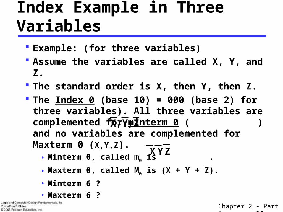
Index Example in Three Variables
Example: (for three variables) Assume the variables are called X, Y, and Z. The standard order is X, then Y, then Z. The Index 0 (base 10) = 000 (base 2) for three
variables). All three variables are complemented for minterm 0 ( ) and no variables are complemented for Maxterm 0 (X,Y,Z).
• Minterm 0, called m0 is .
• Maxterm 0, called M0 is (X + Y + Z).
• Minterm 6 ?
• Maxterm 6 ?
Z,Y,X
ZYX
Chapter 2 - Part 1 37
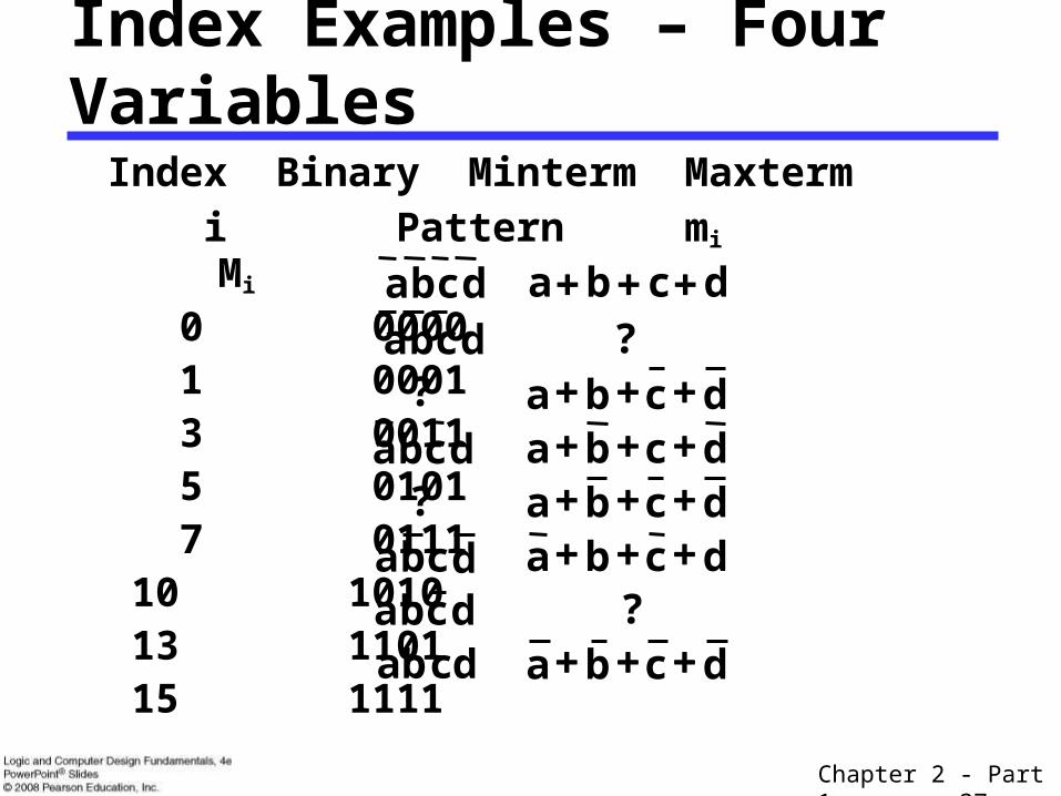
Index Examples – Four Variables
Index Binary Minterm Maxterm i Pattern mi Mi
0 0000 1 0001 3 0011 5 0101 7 0111 10 1010 13 1101 15 1111
dcba dcba dcba
dcba dcba dcba
dcba dcba dcba dbadcba dcba
??
?
?c
Chapter 2 - Part 1 38
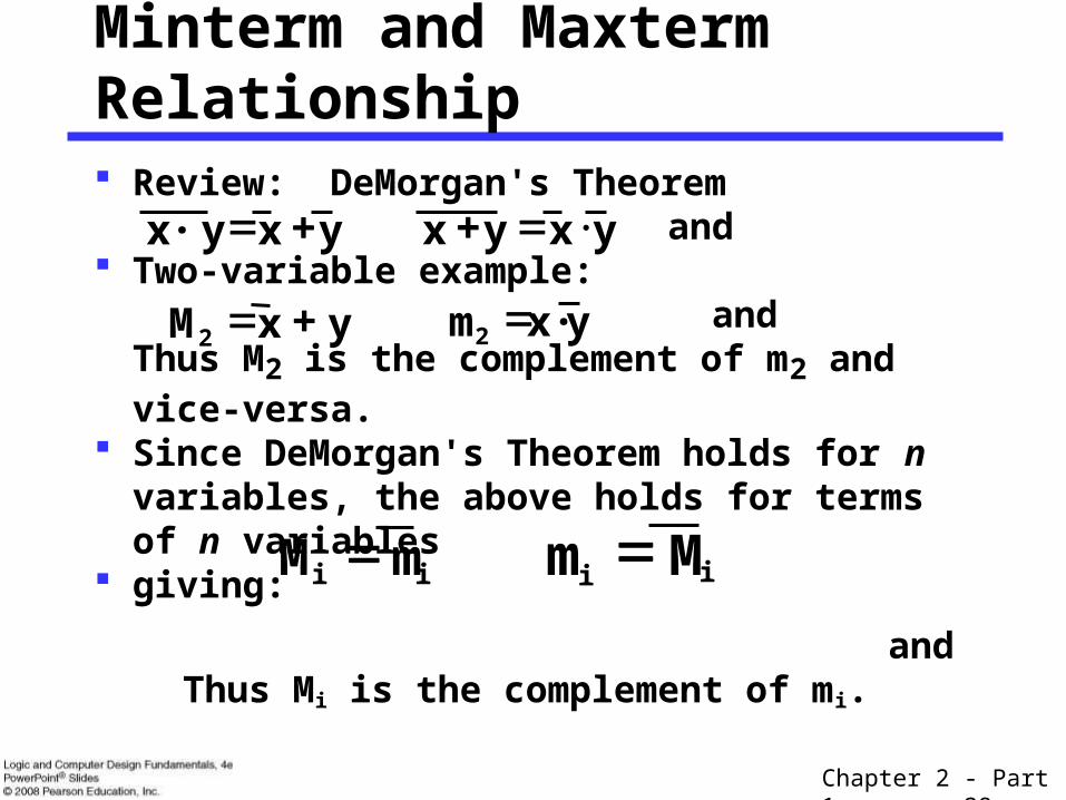
Review: DeMorgan's Theorem and Two-variable example: and
Thus M2 is the complement of m2 and vice-versa. Since DeMorgan's Theorem holds for n variables,
the above holds for terms of n variables giving:
and Thus Mi is the complement of mi.
Minterm and Maxterm Relationship
yx y· x yxyx
y x M2 yx· m2
i mM i ii Mm

Chapter 2 - Part 1 39
Function Tables for Both
Minterms of Maxterms of 2 variables 2 variables
Each column in the maxterm function table is the complement of the column in the minterm function table since Mi is the complement of mi.
x y m0 m1 m2 m3
0 0 1 0 0 0
0 1 0 1 0 0
1 0 0 0 1 0
1 1 0 0 0 1
x y M0 M1 M2 M3
0 0 0 1 1 1
0 1 1 0 1 1
1 0 1 1 0 1
1 1 1 1 1 0
Chapter 2 - Part 1 40
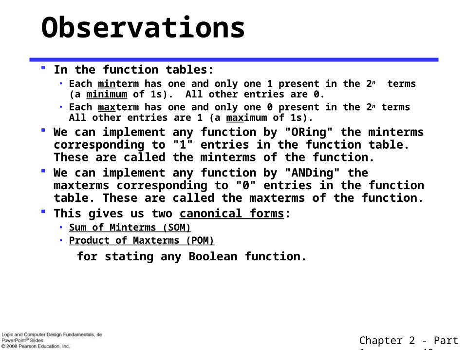
Observations In the function tables:
• Each minterm has one and only one 1 present in the 2n terms (a minimum of 1s). All other entries are 0.
• Each maxterm has one and only one 0 present in the 2n terms All other entries are 1 (a maximum of 1s).
We can implement any function by "ORing" the minterms corresponding to "1" entries in the function table. These are called the minterms of the function.
We can implement any function by "ANDing" the maxterms corresponding to "0" entries in the function table. These are called the maxterms of the function.
This gives us two canonical forms:• Sum of Minterms (SOM)• Product of Maxterms (POM)
for stating any Boolean function.
Chapter 2 - Part 1 41
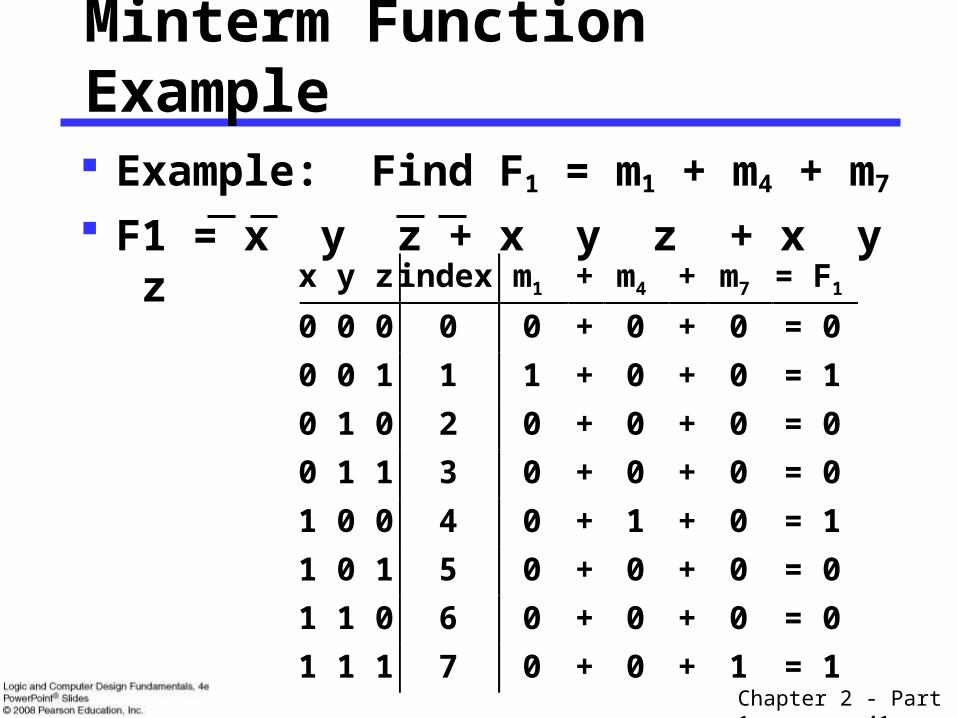
x y z index m1 + m4 + m7 = F1
0 0 0 0 0 + 0 + 0 = 0
0 0 1 1 1 + 0 + 0 = 1
0 1 0 2 0 + 0 + 0 = 0
0 1 1 3 0 + 0 + 0 = 0
1 0 0 4 0 + 1 + 0 = 1
1 0 1 5 0 + 0 + 0 = 0
1 1 0 6 0 + 0 + 0 = 0
1 1 1 7 0 + 0 + 1 = 1
Minterm Function Example
Example: Find F1 = m1 + m4 + m7
F1 = x y z + x y z + x y z
Chapter 2 - Part 1 42
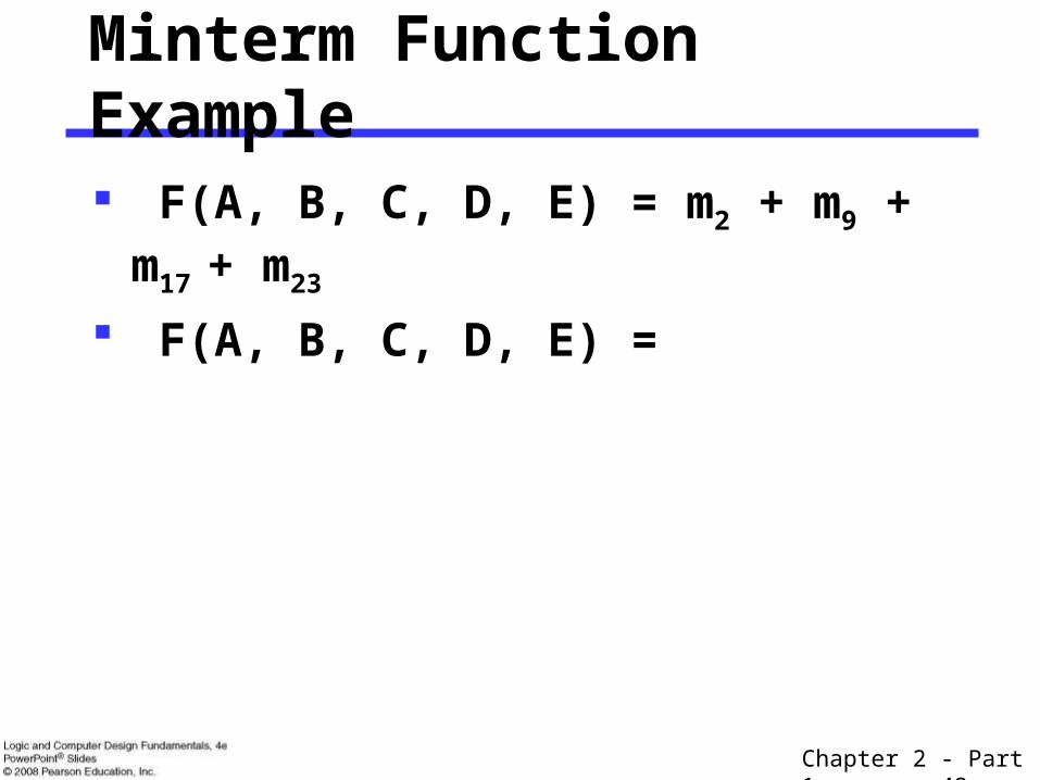
Minterm Function Example
F(A, B, C, D, E) = m2 + m9 + m17 + m23
F(A, B, C, D, E) =

Chapter 2 - Part 1 43
Maxterm Function Example
Example: Implement F1 in maxterms: F1 = M0 · M2 · M3 · M5 · M6
)z y z)·(x y ·(x z) y (x F1 z) y x)·(z y x·(
x y z i M0 M2 M3 M5 M6 = F1 0 0 0 0 0 1 1 1 = 0 0 0 1 1 1 1 1 1 1 = 1 0 1 0 2 1 0 1 1 1 = 0 0 1 1 3 1 1 0 1 1 = 0 1 0 0 4 1 1 1 1 1 = 1 1 0 1 5 1 1 1 0 1 = 0 1 1 0 6 1 1 1 1 0 = 0 1 1 1 7 1
1 1 1 1 = 1
1

Chapter 2 - Part 1 44
Maxterm Function Example
F(A, B,C,D) =
14 11 8 3 M M MM)D,C,B,A(F
Chapter 2 - Part 1 45
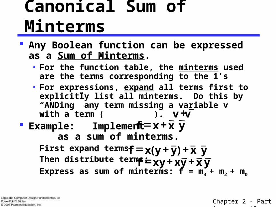
Canonical Sum of Minterms
Any Boolean function can be expressed as a Sum of Minterms.• For the function table, the minterms used are the
terms corresponding to the 1's• For expressions, expand all terms first to explicitly
list all minterms. Do this by “ANDing” any term missing a variable v with a term ( ).
Example: Implement as a sum of minterms.
First expand terms:Then distribute terms:
Express as sum of minterms: f = m3 + m2 + m0
yxxf
yx)yy(xf yxyxxyf
v v

Chapter 2 - Part 1 46
Another SOM Example
Example: There are three variables, A, B, and C which
we take to be the standard order. Expanding the terms with missing variables:
Collect terms (removing all but one of duplicate terms):
Express as SOM:
C B A F

Chapter 2 - Part 1 47
Shorthand SOM Form
From the previous example, we started with:
We ended up with:
F = m1+m4+m5+m6+m7
This can be denoted in the formal shorthand:
Note that we explicitly show the standard variables in order and drop the “m” designators.
)7,6,5,4,1()C,B,A(F m
C B A F
Chapter 2 - Part 1 48
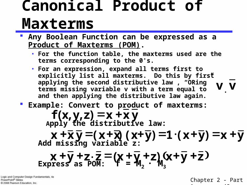
Canonical Product of Maxterms Any Boolean Function can be expressed as a Product of
Maxterms (POM).• For the function table, the maxterms used are the terms
corresponding to the 0's.• For an expression, expand all terms first to explicitly list all
maxterms. Do this by first applying the second distributive law , “ORing” terms missing variable v with a term equal to and then applying the distributive law again.
Example: Convert to product of maxterms:
Apply the distributive law:
Add missing variable z:
Express as POM: f = M2 · M3
yxx)z,y,x(f
yx )y(x 1 )y)(xx(x y xx
zyx)zyx(zzyx
vv
Chapter 2 - Part 1 49
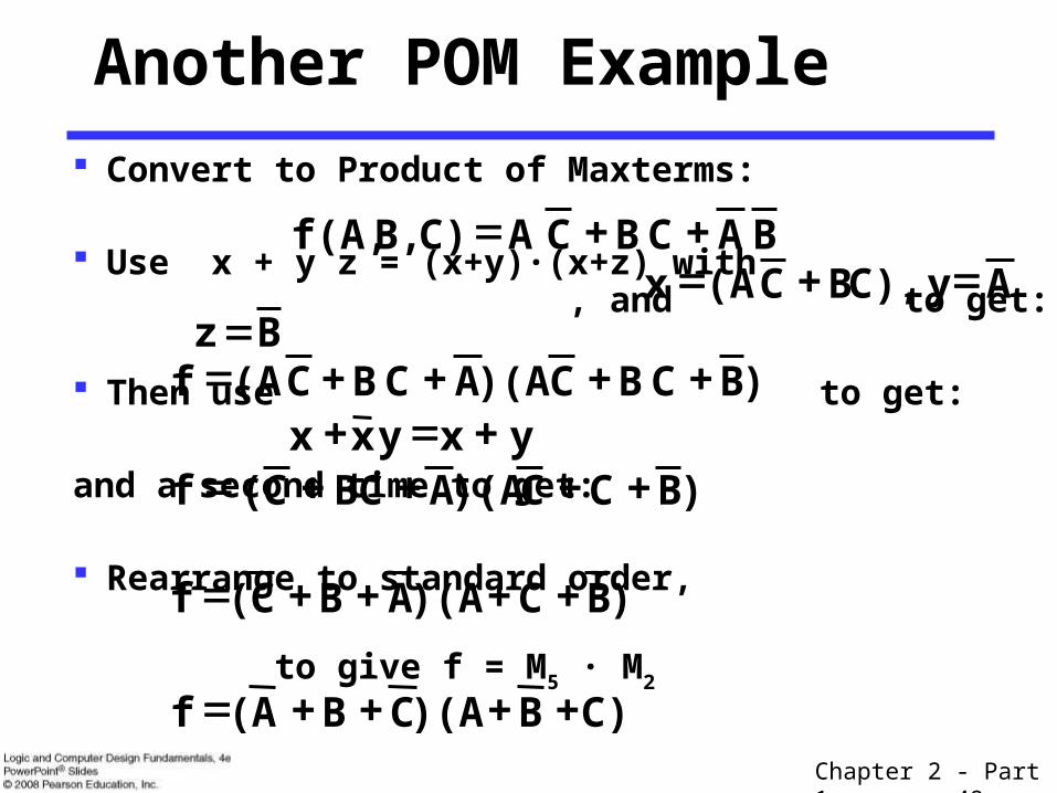
Convert to Product of Maxterms:
Use x + y z = (x+y)·(x+z) with , and to get:
Then use to get:
and a second time to get:
Rearrange to standard order,
to give f = M5 · M2
Another POM Example
BA CB CA C)B,f(A,
B z )B CB C)(AA CB C(A f
y x yx x )B C C)(AA BC C( f
)B C )(AA B C( f
C) B )(AC B A( f
A yC),B (A x C
Chapter 2 - Part 1 50
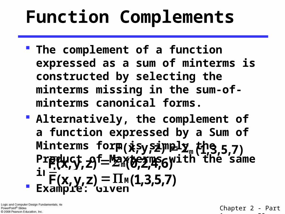
Function Complements
The complement of a function expressed as a sum of minterms is constructed by selecting the minterms missing in the sum-of-minterms canonical forms.
Alternatively, the complement of a function expressed by a Sum of Minterms form is simply the Product of Maxterms with the same indices.
Example: Given )7,5,3,1()z,y,x(F m)6,4,2,0()z,y,x(F m)7,5,3,1()z,y,x(F M

Chapter 2 - Part 1 51
Conversion Between Forms
To convert between sum-of-minterms and product-of-maxterms form (or vice-versa) we follow these steps:• Find the function complement by swapping terms in the list
with terms not in the list.
• Change from products to sums, or vice versa.
Example:Given F as before: Form the Complement: Then use the other form with the same indices – this
forms the complement again, giving the other form of the original function:
)7,5,3,1()z,y,x(F m)6,4,2,0()z,y,x(F m
)6,4,2,0()z,y,x(F M

Chapter 2 - Part 1 52
Standard Sum-of-Products (SOP) form: equations are written as an OR of AND terms
Standard Product-of-Sums (POS) form: equations are written as an AND of OR terms
Examples:• SOP:
• POS:
These “mixed” forms are neither SOP nor POS•
•
Standard Forms
B C B A C B A C · )C B(A · B) (A
C) (A C) B (A B) (A C A C B A
Chapter 2 - Part 1 53
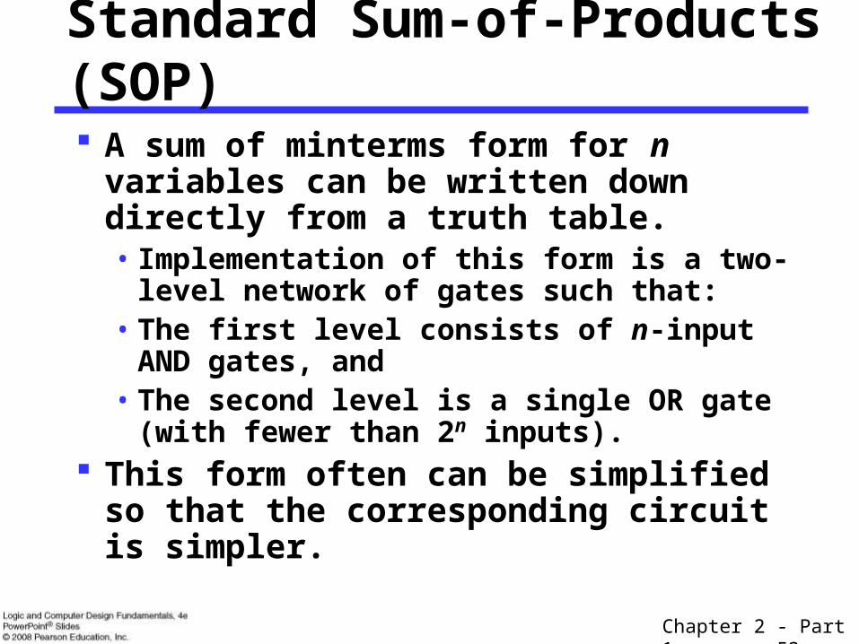
Standard Sum-of-Products (SOP)
A sum of minterms form for n variables can be written down directly from a truth table.• Implementation of this form is a two-level
network of gates such that:• The first level consists of n-input AND gates,
and• The second level is a single OR gate (with
fewer than 2n inputs). This form often can be simplified so that
the corresponding circuit is simpler.

Chapter 2 - Part 1 54
A Simplification Example: Writing the minterm expression: F = A B C + A B C + A B C + ABC + ABC Simplifying: F =
Simplified F contains 3 literals compared to 15 in minterm F
Standard Sum-of-Products (SOP)
)7,6,5,4,1(m)C,B,A(F
Chapter 2 - Part 1 55
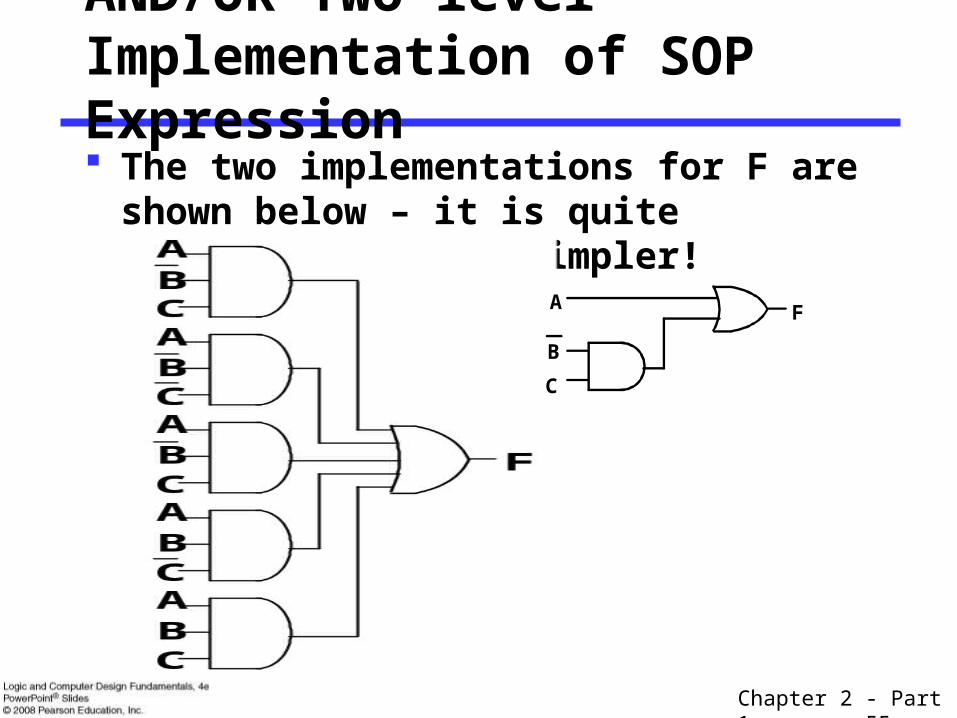
AND/OR Two-level Implementation of SOP Expression The two implementations for F are shown
below – it is quite apparent which is simpler!
F
B
C
A
Chapter 2 - Part 1 56
SOP and POS Observations
The previous examples show that:• Canonical Forms (Sum-of-minterms, Product-of-
Maxterms), or other standard forms (SOP, POS) differ in complexity
• Boolean algebra can be used to manipulate equations into simpler forms.
• Simpler equations lead to simpler two-level implementations
Questions:• How can we attain a “simplest” expression?• Is there only one minimum cost circuit? • The next part will deal with these issues.
Related Documents