Charles Kime & Thomas Kaminski © 2008 Pearson Education, Inc. (Hyperlinks are active in View Show mode) Chapter 2 – Combinational Logic Circuits Part 2 – Circuit Optimization Logic and Computer Design Fundamentals

Welcome message from author
This document is posted to help you gain knowledge. Please leave a comment to let me know what you think about it! Share it to your friends and learn new things together.
Transcript

Charles Kime & Thomas Kaminski
© 2008 Pearson Education, Inc.(Hyperlinks are active in View Show mode)
Chapter 2 – Combinational Logic Circuits
Part 2 – Circuit Optimization
Logic and Computer Design Fundamentals

Chapter 2 - Part 2 2
Overview Part 1 – Gate Circuits and Boolean Equations
• Binary Logic and Gates• Boolean Algebra• Standard Forms
Part 2 – Circuit Optimization• Two-Level Optimization• Map Manipulation• Practical Optimization (Espresso)• Multi-Level Circuit Optimization
Part 3 – Additional Gates and Circuits• Other Gate Types• Exclusive-OR Operator and Gates• High-Impedance Outputs

Chapter 2 - Part 2 3
Circuit Optimization
Goal: To obtain the simplest implementation for a given function
Optimization is a more formal approach to simplification that is performed using a specific procedure or algorithm
Optimization requires a cost criterion to measure the simplicity of a circuit
Distinct cost criteria we will use:• Literal cost (L)• Gate input cost (G)• Gate input cost with NOTs (GN)
Chapter 2 - Part 2 4
D
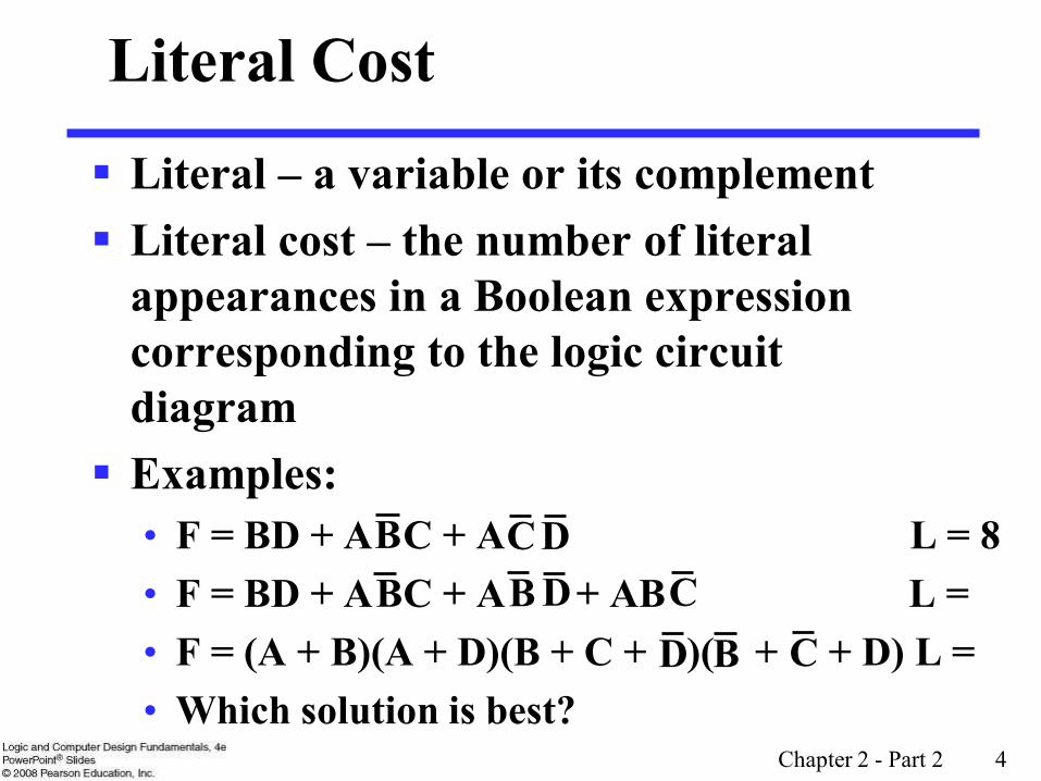
Literal – a variable or its complement Literal cost – the number of literal
appearances in a Boolean expression corresponding to the logic circuit diagram
Examples:• F = BD + A C + A L = 8• F = BD + A C + A + AB L = • F = (A + B)(A + D)(B + C + )( + + D) L =• Which solution is best?
Literal Cost
DB CB B D C
B C

Chapter 2 - Part 2 5
Gate Input Cost Gate input costs - the number of inputs to the gates in the
implementation corresponding exactly to the given equation or equations. (G - inverters not counted, GN - inverters counted)
For SOP and POS equations, it can be found from the equation(s) by finding the sum of:• all literal appearances• the number of terms excluding single literal terms,(G) and• optionally, the number of distinct complemented single literals (GN).
Example:• F = BD + A C + A G = 11, GN = 14• F = BD + A C + A + AB G = , GN = • F = (A + )(A + D)(B + C + )( + + D) G = , GN =• Which solution is best?
DB CB B D C
B D B C
Chapter 2 - Part 2 6
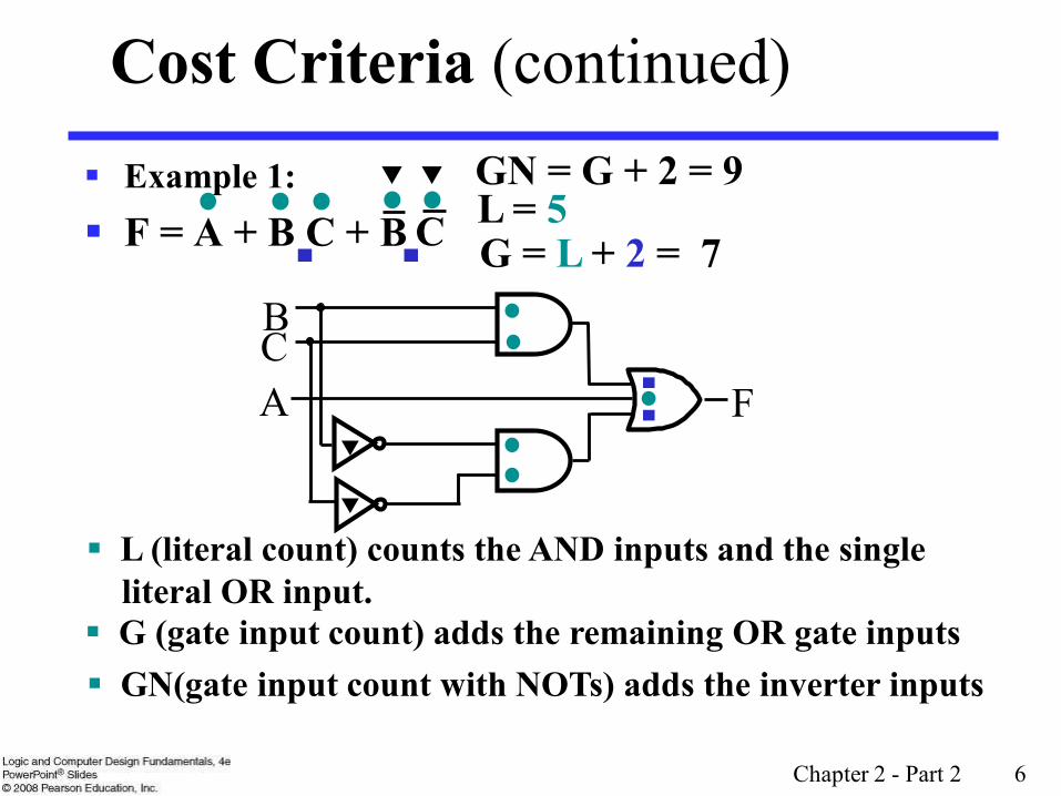
Example 1: F = A + B C +
Cost Criteria (continued)
A
BC
F
B C L = 5
L (literal count) counts the AND inputs and the singleliteral OR input.
G = L + 2 = 7
G (gate input count) adds the remaining OR gate inputs
GN = G + 2 = 9
GN(gate input count with NOTs) adds the inverter inputs

Chapter 2 - Part 2 7
Example 2: F = A B C + L = 6 G = 8 GN = 11 F = (A + )( + C)( + B) L = 6 G = 9 GN = 12 Same function and same
literal cost But first circuit has better
gate input count and bettergate input count with NOTs
Select it!
Cost Criteria (continued)
BC
A
ABC
F
C B
F
ABC
A
Chapter 2 - Part 2 8
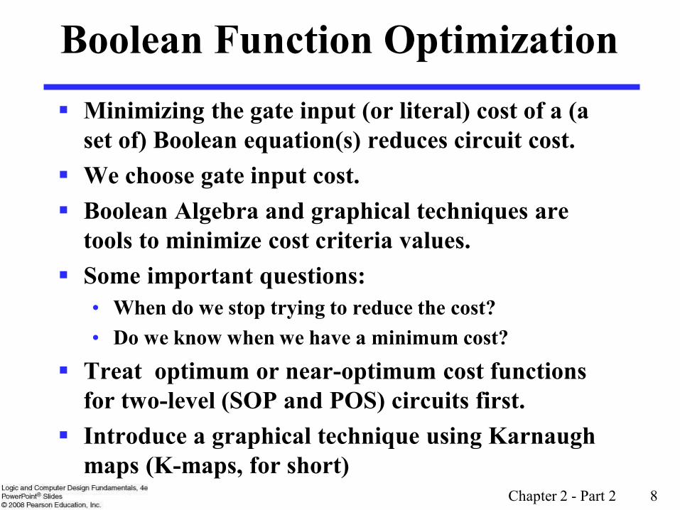
Boolean Function Optimization Minimizing the gate input (or literal) cost of a (a
set of) Boolean equation(s) reduces circuit cost. We choose gate input cost. Boolean Algebra and graphical techniques are
tools to minimize cost criteria values. Some important questions:
• When do we stop trying to reduce the cost?• Do we know when we have a minimum cost?
Treat optimum or near-optimum cost functionsfor two-level (SOP and POS) circuits first.
Introduce a graphical technique using Karnaugh maps (K-maps, for short)

Chapter 2 - Part 2 9
Karnaugh Maps (K-map)
A K-map is a collection of squares• Each square represents a minterm• The collection of squares is a graphical representation of a
Boolean function• Adjacent squares differ in the value of one variable• Alternative algebraic expressions for the same function are
derived by recognizing patterns of squares The K-map can be viewed as
• A reorganized version of the truth table• A topologically-warped Venn diagram as used to visualize sets in
algebra of sets

Chapter 2 - Part 2 10
Some Uses of K-Maps Provide a means for:
• Finding optimum or near optimum SOP and POS standard forms, and two-level AND/OR and OR/AND circuit
implementationsfor functions with small numbers of variables
• Visualizing concepts related to manipulating Boolean expressions, and
• Demonstrating concepts used by computer-aided design programs to simplify large circuits

Chapter 2 - Part 2 11
Two Variable Maps A 2-variable Karnaugh Map:
• Note that minterm m0 andminterm m1 are “adjacent”
and differ in the value of thevariable y
• Similarly, minterm m0 andminterm m2 differ in the x variable.
• Also, m1 and m3 differ in the x variable as well.
• Finally, m2 and m3 differ in the value of the variable y
y = 0 y = 1
x = 0 m0 = m1 =
x = 1 m2 = m3 =yx yx
yx yx
Chapter 2 - Part 2 12
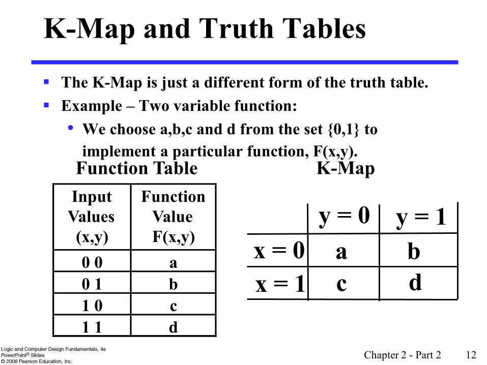
K-Map and Truth Tables
The K-Map is just a different form of the truth table. Example – Two variable function:
• We choose a,b,c and d from the set {0,1} to implement a particular function, F(x,y).
Function Table K-MapInput Values(x,y)
Function ValueF(x,y)
0 0 a0 1 b1 0 c1 1 d
y = 0 y = 1x = 0 a bx = 1 c d

Chapter 2 - Part 2 13
K-Map Function Representation
Example: F(x,y) = x
For function F(x,y), the two adjacent cells containing 1’s can be combined using the
Minimization Theorem:
F = x y = 0 y = 1
x = 0 0 0
x = 1 1 1
xyxyx)y,x(F =+=

Chapter 2 - Part 2 14
K-Map Function Representation
Example: G(x,y) = x + y
For G(x,y), two pairs of adjacent cells containing 1’s can be combined using the Minimization
Theorem:
G = x+y y = 0 y = 1
x = 0 0 1
x = 1 1 1
( ) ( ) yxyxxyyxyx)y,x(G +=+++=
Duplicate xy

Chapter 2 - Part 2 15
Three Variable Maps
A three-variable K-map:
Where each minterm corresponds to the product terms:
Note that if the binary value for an index differs in one bit position, the minterms are adjacent on the K-Map
yz=00 yz=01 yz=11 yz=10
x=0 m0 m1 m3 m2
x=1 m4 m5 m7 m6
yz=00 yz=01 yz=11 yz=10
x=0
x=1
zyx zyx zyx zyxzyx zyx zyx zyx

Chapter 2 - Part 2 16
Alternative Map Labeling
Map use largely involves:• Entering values into the map, and• Reading off product terms from the
map. Alternate labelings are useful:
y
zx
10 2
4
3
5 67
xy
zz
yy z
z
10 2
4
3
5 67
x01
00 01 11 10
x

Chapter 2 - Part 2 17
Example Functions
By convention, we represent the minterms of F by a "1" in the map and leave the minterms of blank
Example:
Example:
Learn the locations of the 8 indices based on the variable order shown (x, most significantand z, least significant) on themap boundaries
y
x10 2
4
3
5 67
111
1
z
x
y10 2
4
3
5 671 111
z
(2,3,4,5) z)y,F(x, m=
(3,4,6,7) c)b,G(a, m=
F
Chapter 2 - Part 2 18
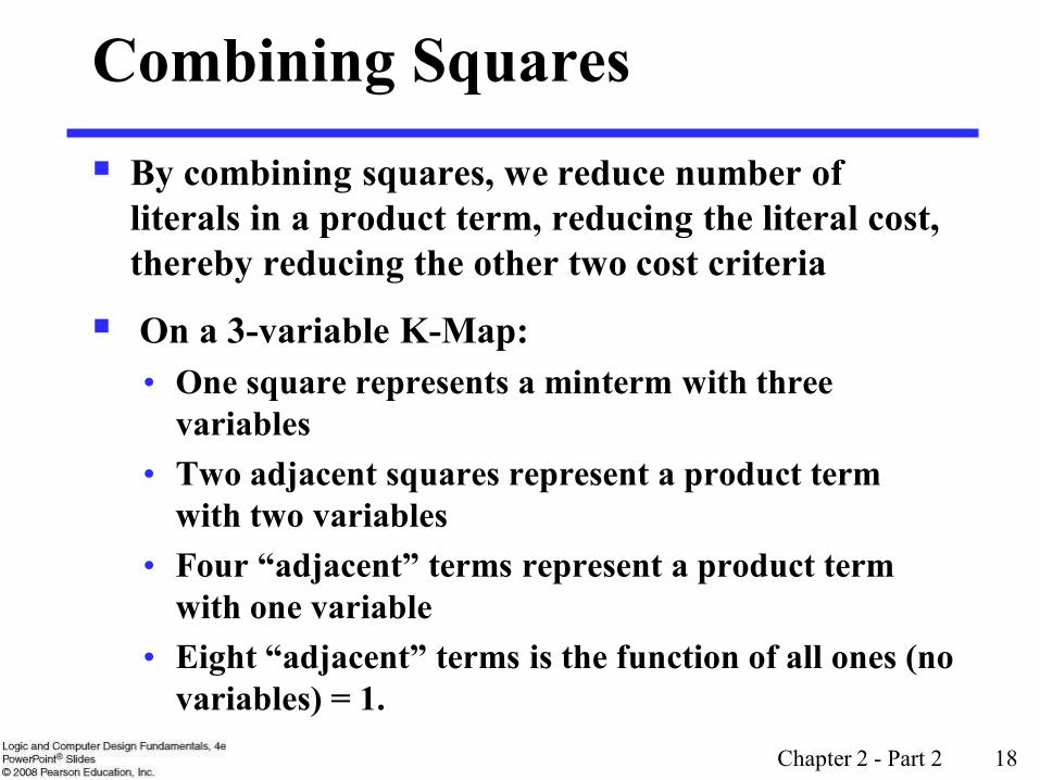
Combining Squares By combining squares, we reduce number of
literals in a product term, reducing the literal cost, thereby reducing the other two cost criteria
On a 3-variable K-Map:• One square represents a minterm with three
variables• Two adjacent squares represent a product term
with two variables• Four “adjacent” terms represent a product term
with one variable• Eight “adjacent” terms is the function of all ones (no
variables) = 1.

Chapter 2 - Part 2 19
Example: Combining Squares
Example: Let
Applying the Minimization Theorem three times:
Thus the four terms that form a 2 × 2 square correspond to the term "y".
y=zyyz +=
zyxzyxzyxzyx)z,y,x(F +++=
x
y10 2
4
3
5 671 111
z
m(2,3,6,7) F =

Chapter 2 - Part 2 20
Three-Variable Maps
Reduced literal product terms for SOP standard forms correspond to rectangles on K-maps containing cell counts that are powers of 2.
Rectangles of 2 cells represent 2 adjacent minterms; of 4 cells represent 4 minterms that form a “pairwise adjacent” ring.
Rectangles can contain non-adjacent cells as illustrated by the “pairwise adjacent” ring
above.

Chapter 2 - Part 2 21
Three-Variable Maps
Topological warps of 3-variable K-maps that show all adjacencies: Venn Diagram Cylinder
Y Z
X
1376 5
4
2
0

Chapter 2 - Part 2 22
Three-Variable Maps
Example Shapes of 2-cell Rectangles:
Read off the product terms for the rectangles shown
y0 1 3 2
5 64 7xz

Chapter 2 - Part 2 23
Three-Variable Maps
Example Shapes of 4-cell Rectangles:
Read off the product terms for the rectangles shown
y0 1 3 2
5 64 7xz

Chapter 2 - Part 2 24
Three Variable Maps
z)y,F(x, =
y
11
x
z
1 1
1
z
z
yx+
yx
K-Maps can be used to simplify Boolean functions bysystematic methods. Terms are selected to cover the“1s”in the map.
Example: Simplify )(1,2,3,5,7 z)y,F(x, m=
Chapter 2 - Part 2 25
Three-Variable Map Simplification Use a K-map to find an optimum SOP
equation for ,7)(0,1,2,4,6 Z)Y,F(X, m=

Chapter 2 - Part 2 26
Four Variable Maps
Map and location of minterms:
8 9 1011
12 13 1415
0 1 3 2
5 64 7
X
Y
Z
WVariable Order

Chapter 2 - Part 2 27
Four Variable Terms
Four variable maps can have rectangles corresponding to:• A single 1 = 4 variables, (i.e. Minterm)• Two 1s = 3 variables,• Four 1s = 2 variables• Eight 1s = 1 variable,• Sixteen 1s = zero variables (i.e.
Constant "1")

Chapter 2 - Part 2 28
Four-Variable Maps
Example Shapes of Rectangles:
8 9 1011
12 13 1415
0 1 3 2
5 64 7
X
Y
Z
W

Chapter 2 - Part 2 29
Four-Variable Maps
Example Shapes of Rectangles:
X
Y
Z
8 9 1011
12 13 1415
0 1 3 2
5 64 7
W

Chapter 2 - Part 2 30
Four-Variable Map Simplification )8,10,13,152,4,5,6,7,(0,Z)Y,X,F(W, m=

Chapter 2 - Part 2 31
3,14,15
Four-Variable Map Simplification )(3,4,5,7,9,1Z)Y,X,F(W, m=
Chapter 2 - Part 2 32
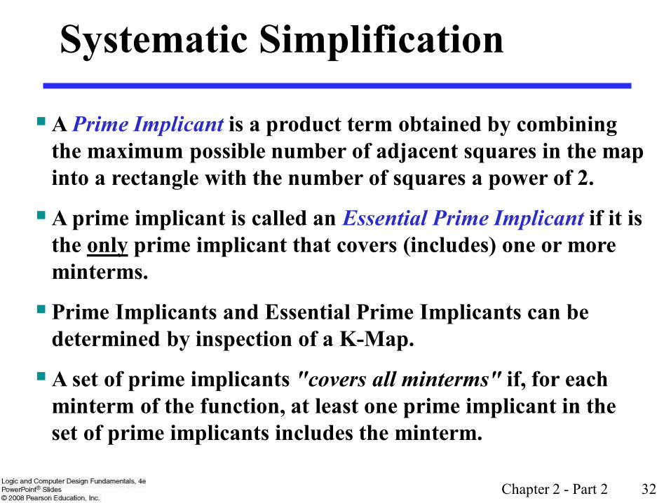
Systematic Simplification
A Prime Implicant is a product term obtained by combining the maximum possible number of adjacent squares in the map into a rectangle with the number of squares a power of 2.
A prime implicant is called an Essential Prime Implicant if it is the only prime implicant that covers (includes) one or more minterms.
Prime Implicants and Essential Prime Implicants can be determined by inspection of a K-Map.
A set of prime implicants "covers all minterms" if, for each minterm of the function, at least one prime implicant in the set of prime implicants includes the minterm.

Chapter 2 - Part 2 33
DB
CB
1 1
1 1
1 1
B
D
A
1 1
1 1
1
Example of Prime Implicants
Find ALL Prime ImplicantsESSENTIAL Prime Implicants
C
BD
CD
BD
Minterms covered by single prime implicant
DB
1 1
1 1
1 1
B
C
D
A
1 1
1 1
1
AD
BA
Chapter 2 - Part 2 34
Prime Implicant Practice
Find all prime implicants for:13,14,15),10,11,12,(0,2,3,8,9 D)C,B,F(A, m=

Chapter 2 - Part 2 35
Another Example
Find all prime implicants for:
• Hint: There are seven prime implicants!15),12,13,14,(0,2,3,4,7 D)C,B,G(A, m=
Chapter 2 - Part 2 36
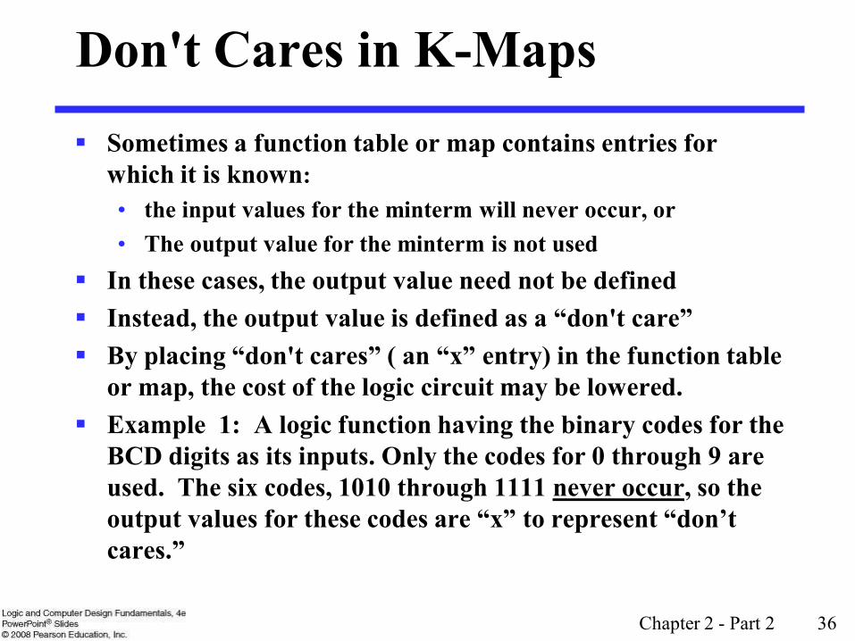
Sometimes a function table or map contains entries for which it is known:• the input values for the minterm will never occur, or• The output value for the minterm is not used
In these cases, the output value need not be defined Instead, the output value is defined as a “don't care”
By placing “don't cares” ( an “x” entry) in the function table
or map, the cost of the logic circuit may be lowered. Example 1: A logic function having the binary codes for the
BCD digits as its inputs. Only the codes for 0 through 9 are used. The six codes, 1010 through 1111 never occur, so the output values for these codes are “x” to represent “don’t
cares.”
Don't Cares in K-Maps

Chapter 2 - Part 2 37
Example 2: A circuit that represents a very common situation that occurs in computer design has two distinct sets of input variables:• A, B, and C which take on all possible combinations, and• Y which takes on values 0 or 1.
and a single output Z. The circuit that receives the output Z observes it only for combinations of A, B, and C such A = 1 and B = 1 or C = 0, otherwise ignoring it. Thus, Z is specified only for those combinations, and for all other combinations of A, B, and C, Z is a don’t care. Specifically, Z must be specified for AB + C = 1, and is a don’t care for :
AB + C = (A + B)C = AC + BC = 1 Ultimately, each don’t care “x” entry may take on either a 0 or 1
value in resulting solutions For example, an “x” may take on value “0” in an SOP solution and
value “1” in a POS solution, or vice-versa. Any minterm with value “x” need not be covered by a prime
implicant.
Don't Cares in K-Maps

Chapter 2 - Part 2 38
Example: BCD “5 or More”
The map below gives a function F1(w,x,y,z) which is defined as "5 or more" over BCD inputs. With the don't cares used for the 6 non-BCD combinations:
F1 (w,x,y,z) = w + x z + x y G = 7 This is much lower in cost than F2 where
the “don't cares” were treated as "0s."
G = 12 For this particular function, cost G for the
POS solution for F1(w,x,y,z) is not changed by using the don't cares.z
w
0 1 3 2
4 5 7 6
12 13 15 14
8 9 11 10
1
1
11
1
X X X
X X
X
0 0 0 0
0x
y
yxwyxwzxwz) y,x,F2(w, ++=

Chapter 2 - Part 2 39
Product of Sums Example
Find the optimum POS solution:
• Hint: Use and complement it to get the result.
,13,14,15)(3,9,11,12 D)C,B,F(A, m +=(1,4,6) d
F

Chapter 2 - Part 2 40
Optimization Algorithm
Find all prime implicants. Include all essential prime implicants in the
solution Select a minimum cost set of non-essential
prime implicants to cover all minterms not yet covered:• Obtaining an optimum solution: See Reading
Supplement - More on Optimization• Obtaining a good simplified solution: Use the
Selection Rule

Chapter 2 - Part 2 41
Prime Implicant Selection Rule
Minimize the overlap among prime implicants as much as possible. In particular, in the final solution, make sure that each prime implicant selected includes at least one minterm not included in any other prime implicant selected.

Chapter 2 - Part 2 42
Selection Rule Example
Simplify F(A, B, C, D) given on the K-map.
1
1
1
1 1
1
1
B
D
A
C
1
1
1
1
1
1 1
1
1
B
D
A
C
1
1
Essential
Minterms covered by essential prime implicants
Selected
Chapter 2 - Part 2 43
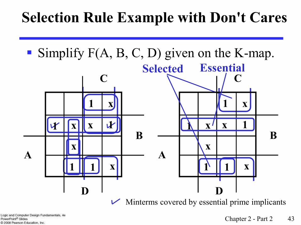
Selection Rule Example with Don't Cares
Simplify F(A, B, C, D) given on the K-map. Selected
Minterms covered by essential prime implicants
1
1
x
x
x x
x
1
B
D
A
C
1
1 1
1
x
x
x x
x
1
B
D
A
C
1
1
Essential

Chapter 2 - Part 2 44
Terms of Use All (or portions) of this material © 2008 by Pearson
Education, Inc. Permission is given to incorporate this material or
adaptations thereof into classroom presentations and handouts to instructors in courses adopting the latest edition of Logic and Computer Design Fundamentals as the course textbook.
These materials or adaptations thereof are not to be sold or otherwise offered for consideration.
This Terms of Use slide or page is to be included within the original materials or any adaptations thereof.
Related Documents


