Chapter 2 Basic Concepts • Line Configuration • Topology • Transmission Mode • Categories of Networks • Internetworks WCB/McGraw-Hill The McGraw-Hill Companies, Inc., 1998

Welcome message from author
This document is posted to help you gain knowledge. Please leave a comment to let me know what you think about it! Share it to your friends and learn new things together.
Transcript
Chapter 2
Basic Concepts
• Line Configuration• Topology• Transmission Mode• Categories of Networks• Internetworks
WCB/McGraw-Hill The McGraw-Hill Companies, Inc., 1998

Figure 2-1
WCB/McGraw-Hill The McGraw-Hill Companies, Inc., 1998

Figure 2-2
WCB/McGraw-Hill The McGraw-Hill Companies, Inc., 1998
Point-to-Point Line Configuration

Figure 2-2-continued
WCB/McGraw-Hill The McGraw-Hill Companies, Inc., 1998
Point-to-Point Line Configuration

Figure 2-2-continued
WCB/McGraw-Hill The McGraw-Hill Companies, Inc., 1998
Point-to-Point Line Configuration

Figure 2-3
WCB/McGraw-Hill The McGraw-Hill Companies, Inc., 1998
Multipoint Line Configuration

Figure 2-4
WCB/McGraw-Hill The McGraw-Hill Companies, Inc., 1998

Figure 2-5
WCB/McGraw-Hill The McGraw-Hill Companies, Inc., 1998
Mesh Topology

A mesh offers several advantages over other network topologies. First, the use ofdedicated links guarantees that each connection can carry its own data load, thus eliminatingthe traffic problems that can occur when links must be shared by multiple devices.

Second, a mesh topology is robust. If one link becomes unusable, it does not incapacitate the entire system. Third, there is the advantage of privacy or security. When every message travels along a dedicated line, only the intended recipient sees it. Physical boundaries prevent other users from gaining access to messages

Finally, point-to-pointlinks make fault identification and fault isolation easy.
The main disadvantages of a mesh are related to the amount of cabling and the number of I/O ports required. First, because every device must be connected to everyother device, installation and reconnection are difficult.

Second, the sheer bulk of the wiring can be greater than the available space (in walls, ceilings, or floors) can accommodate.Finally, the hardware required to connect each link (I/O ports and cable) can beprohibitively expensive. For these reasons a mesh topology is usually implemented in alimited fashion,

Figure 2-6
WCB/McGraw-Hill The McGraw-Hill Companies, Inc., 1998
Star Topology

Star Topology In a star topology, each device has a dedicated point-to-point linkonly to a central controller, usually called a hub. The devices are not directly linked toone another
Unlike a mesh topology, a star topology does not allow direct trafficbetween devices. The controller acts as an exchange: If one device wants to send data toanother, it sends the data to the controller, which then relays the data to the other connecteddevice

A star topology is less expensive than a mesh topology. In a star, each device needsonly one link and one I/O port to connect it to any number of others. This factor alsomakes it easy to install and reconfigure. Far less cabling needs to be housed, and additions,moves, and deletions involve only one connection: between that device and the hub.

Other advantages include robustness. If one link fails, only that link is affected. All other links remain active. This factor also lends itself to easy fault identification and fault isolation. As long as the hub is working, it can be used to monitor link problems and bypass defective links

One big disadvantage of a star topology is the dependency of the whole topologyon one single point, the hub. If the hub goes down, the whole system is dead.

Although a star requires far less cable than a mesh, each node must be linked to acentral hub. For this reason, often more cabling is required in a star than in some othertopologies (such as ring or bus).The star topology is used in local-area networks (LANs)
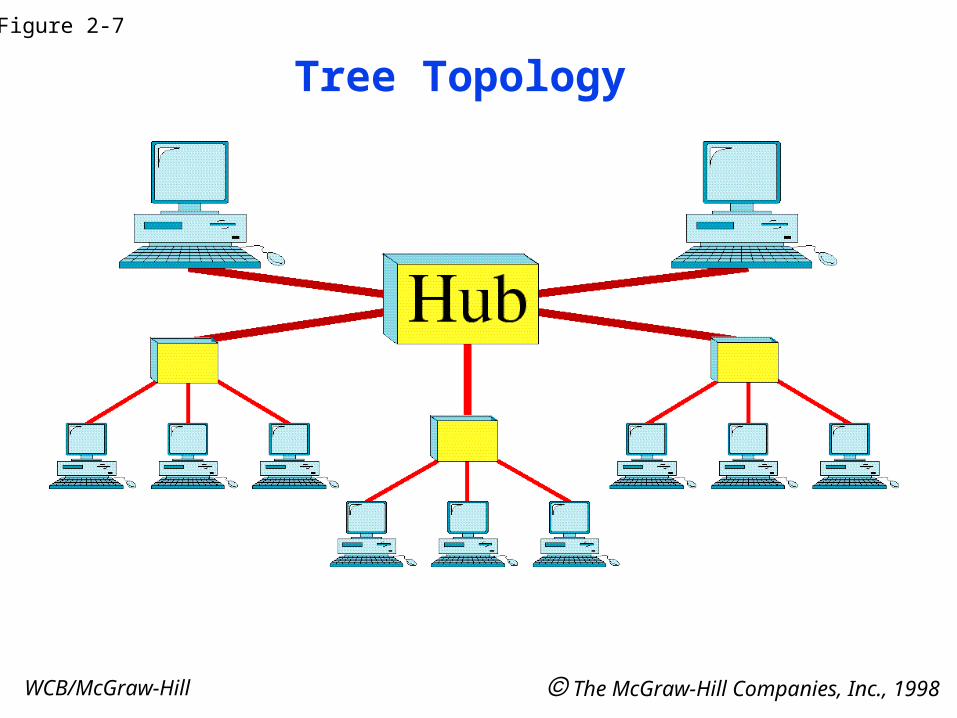
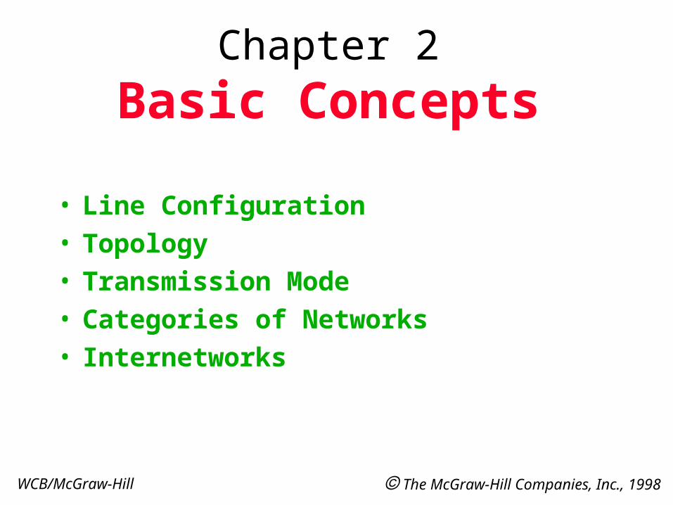
Figure 2-7
WCB/McGraw-Hill The McGraw-Hill Companies, Inc., 1998
Tree Topology

Figure 2-8
WCB/McGraw-Hill The McGraw-Hill Companies, Inc., 1998
Bus Topology

Bus Topology The preceding examples all describe point-to-point connections. A bustopology, on the other hand, is multipoint. One long cable acts as a backbone to link allthe devices in a network

Nodes are connected to the bus cable by drop lines and taps. A drop line is a connection running between the device and the main cable. A tap is a connector that eithersplices into the main cable or punctures the sheathing of a cable to create a contact with the metallic core.
As a signal travels along the backbone, some of its energy is transformedinto heat. Therefore, it becomes weaker and weaker as it travels farther and farther. Forthis reason there is a limit on the number of taps a bus can support and on the distancebetween those taps.

Advantages of a bus topology include ease of installation. Backbone cable can be laid along the most efficient path, then connected to the nodes by drop lines of various lengths. In this way, a bus uses less cabling than mesh or star topologies.

Disadvantages include difficult reconnection and fault isolation. A bus is usually designed to be optimally efficient at installation. It can therefore be difficult to add newdevices. Signal reflection at the taps can cause degradation in quality. This degradation can be controlled by limiting the number and spacing of devices connected to a givenlength of cable. Adding new devices may therefore require modification or replacement of the backbone.

Figure 2-9
WCB/McGraw-Hill The McGraw-Hill Companies, Inc., 1998
Ring Topology

Figure 2-10
WCB/McGraw-Hill The McGraw-Hill Companies, Inc., 1998
Hybrid Topology
Related Documents