Chapter 2 Chapter 2 Elements of photographic Elements of photographic systems systems Introduction to Remote Sensing Instructor: Dr. Cheng -Chien Liu Department of Earth Science National Cheng-Kung University Last updated: 13 March 2003

Chapter 2
Jan 02, 2016
Chapter 2. Elements of photographic systems Introduction to Remote Sensing Instructor: Dr. Cheng-Chien Liu Department of Earth Science National Cheng-Kung University Last updated: 13 March 2003. 2.1Introduction. Advantages of aerial photography Improved vantage point - PowerPoint PPT Presentation
Welcome message from author
This document is posted to help you gain knowledge. Please leave a comment to let me know what you think about it! Share it to your friends and learn new things together.
Transcript
Chapter 2Chapter 2
Elements of photographic systemsElements of photographic systems
Introduction to Remote SensingInstructor: Dr. Cheng-Chien Liu
Department of Earth Science
National Cheng-Kung University
Last updated: 13 March 2003

2.12.1 Introduction Introduction
Advantages of aerial photographyAdvantages of aerial photography• Improved vantage point
• Capability to stop action
• Permanent recording
• Broadened spectral sensitivity
• Increased spatial resolution and geometric fidelity

2.22.2 Early history of aerial Early history of aerial photographyphotography
• 1839 photography
• 1840 use of photography for topographic surveying
• 1858 aerial photograph (balloon)
• 1860 Fig. 2.1: the earliest existing aerial photograph
• 1882 use kite to obtain aerial photograph

2.22.2 Early history of aerial Early history of aerial photography (cont.)photography (cont.)
• 1890 the first kite aerial photograph
• 1906 Fig 2.2: the world-wide known aerial photograph obtained from kite
1890 the giant camera 1.4 x 2.4m
• 1903 Airplane
• 1909 Fig 2.3: The first aerial motion picture
• World War I & II Military purposes
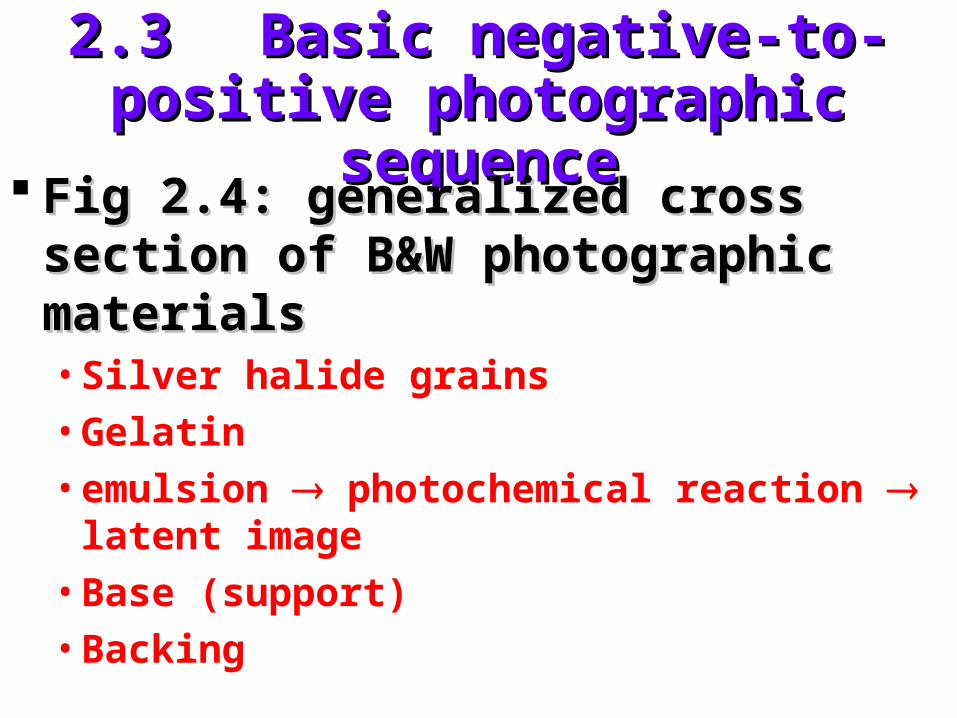
2.32.3 Basic negative-to-positive Basic negative-to-positive photographic sequencephotographic sequence
Fig 2.4: generalized cross section of Fig 2.4: generalized cross section of B&W photographic materialsB&W photographic materials• Silver halide grains
• Gelatin
• emulsion photochemical reaction latent image
• Base (support)
• Backing
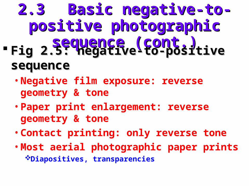
2.32.3 Basic negative-to-positive Basic negative-to-positive photographic sequence (cont.)photographic sequence (cont.)
Fig 2.5: negative-to-positive sequenceFig 2.5: negative-to-positive sequence• Negative film exposure: reverse geometry &
tone
• Paper print enlargement: reverse geometry & tone
• Contact printing: only reverse tone
• Most aerial photographic paper printsDiapositives, transparencies
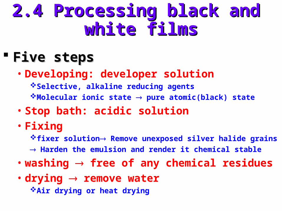
2.4 Processing black and 2.4 Processing black and white filmswhite films
Five stepsFive steps• Developing: developer solution
Selective, alkaline reducing agentsMolecular ionic state pure atomic(black) state
• Stop bath: acidic solution• Fixing
fixer solution Remove unexposed silver halide grains
Harden the emulsion and render it chemical stable
• washing free of any chemical residues• drying remove water
Air drying or heat drying

2.5 Film exposure2.5 Film exposure
The simple cameraThe simple camera• Fig 2.6: comparison between pinhole and
simple lens camerasDiaphragm lens diameterShutter duration of exposure

2.5 Film exposure (cont.)2.5 Film exposure (cont.)
FocusFocus• Equation of focusing
Focal length : fobject distance : oimage distance : i
• Depth of field:f is fixed, charge o change i,
there exists a limited range of i depth of fieldfor aerial photography o i f
oif
111

2.5 Film exposure (cont.)2.5 Film exposure (cont.)
ExposureExposure• equation of exposure:
Film exposure: E (J mm-2)Scene brightness: S (J mm-2 s-1) Diameter of lens opening: d (mm)Exposure time: t (sec)Lens focal length: f (mm)
2
2
4 f
tsdE

2.5 Film exposure (cont.)2.5 Film exposure (cont.)
Aperture setting (f-stop) : Aperture setting (f-stop) : FF = = ff//dd
• F d E • For a fixed value of E: Ft1/2
t stop action, prevent blurring the case of aerial photography
d F useful under low light conditiond F depth of field Lens speed F=f/dmax
• Example 2.2
22
2
44 F
st
f
tsdE

2.5 Film exposure (cont.)2.5 Film exposure (cont.)
Geometric factors influencing film Geometric factors influencing film exposureexposure• Extraneous effect
those factors influence exposure measurements, but have nothing to do with true changes in ground cover type or condition
Geometric atmospheric
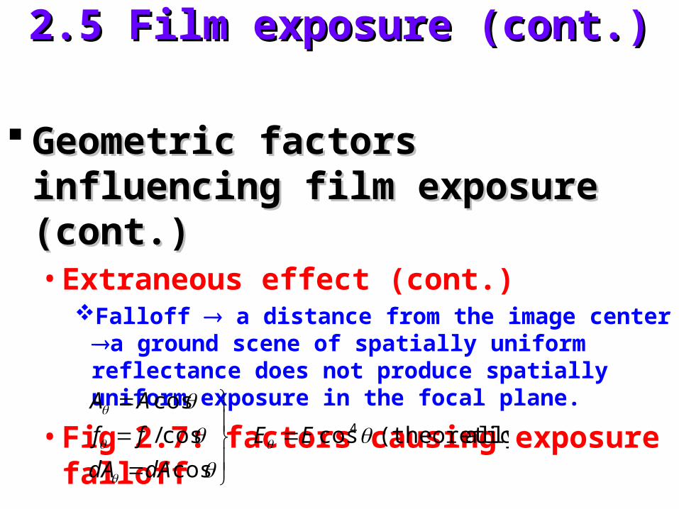
2.5 Film exposure (cont.)2.5 Film exposure (cont.)
Geometric factors influencing film Geometric factors influencing film exposure (cont.)exposure (cont.)• Extraneous effect (cont.)
Falloff a distance from the image center a ground scene of spatially uniform reflectance does not produce spatially uniform exposure in the focal plane.
• Fig 2.7: factors causing exposure falloff
cos
cos/
cos
dAdA
ff
AA
ally)(theoretic cos4 EE

2.5 Film exposure (cont.)2.5 Film exposure (cont.)
Geometric factors influencing film Geometric factors influencing film exposure (cont.)exposure (cont.)• Vignetting effect
internal shadowing resulting from the lens mounts and other aperture surfaces within the camera. It varies from camera to camera and varies with aperture setting for any given camera.
Anti-vignetting filter (see §2.11)

2.5 Film exposure (cont.)2.5 Film exposure (cont.)
Geometric factors influencing film Geometric factors influencing film exposure (cont.)exposure (cont.)• Correction model radiometric calibration
(for given F)Photograph a scene of uniform rightness measure exposure
at various location identify the relationship E = E0cosnModern camera : n = 1.5 ~ 4
2.5 Film exposure (cont.)2.5 Film exposure (cont.)
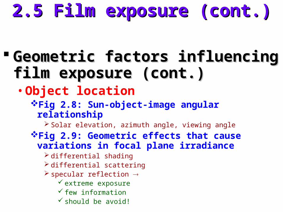
Geometric factors influencing film Geometric factors influencing film exposure (cont.)exposure (cont.)• Object location
Fig 2.8: Sun-object-image angular relationship Solar elevation, azimuth angle, viewing angle
Fig 2.9: Geometric effects that cause variations in focal plane irradiance
differential shading differential scattering specular reflection
extreme exposure few information should be avoid!
2.6 Film density and characteristic 2.6 Film density and characteristic curvescurves
Radiometric characteristicsRadiometric characteristics• how a specific film, exposed and processed
under specific conditions, responds to scene energy of varying intensity
• Important for photographic image analysis
• Tonal values ground phenomenon
(darkness) (crop yield)
Photograph Photograph visual records visual records many many energy detectors (silver halide grains)energy detectors (silver halide grains)
2.6 Film density and characteristic 2.6 Film density and characteristic curves (cont.)curves (cont.)
Film exposureFilm exposure• Instantly open energy reflectance
exposure
• Theoretically: reflectance & fn()
• Unit:meter-candle-second (MCS) or ergs/cm2
MCS is an absolute unit, based on standard observer that is defined photometric.
We will deal with “relative exposures”
• Transmittance:lightincident total
throughpassinglight T

2.6 Film density and characteristic 2.6 Film density and characteristic curves (cont.)curves (cont.)
Film exposure (cont.)Film exposure (cont.)• Opacity: O 1/T• Density: D log(O) log (1/T)
Transmission densitometerReflectance densitometerFig 2.11, Table 2.1
• B&W film AgBr• Color film 3 dye layers filter max absorption• D-logE curve
Each film has a unique D-logE curveAlso called H&D curve
2.6 Film density and characteristic 2.6 Film density and characteristic curves (cont.)curves (cont.)
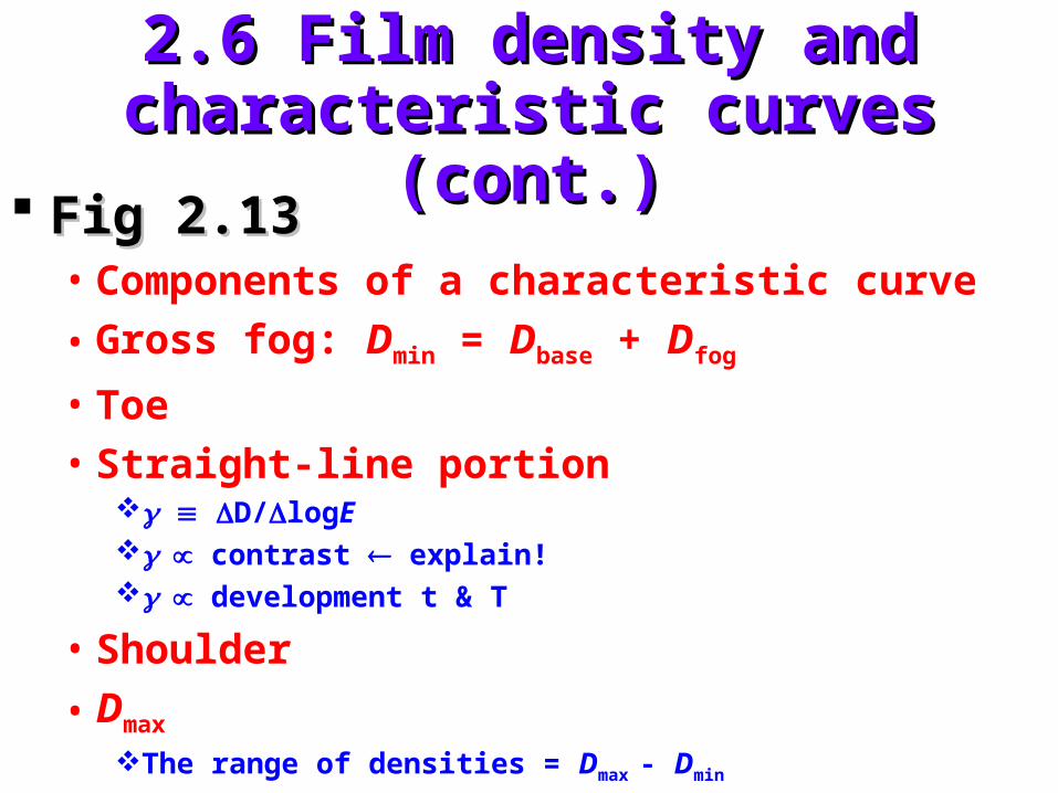
Fig 2.13 Fig 2.13 • Components of a characteristic curve
• Gross fog: Dmin = Dbase + Dfog
• Toe• Straight-line portion
D/logE contrast explain! development t & T
• Shoulder
• Dmax
The range of densities = Dmax - Dmin
2.6 Film density and characteristic 2.6 Film density and characteristic curves (cont.)curves (cont.)
Film speedFilm speed• The sensitivity of the film to light
• Speed exposure time • Speed size of AgBr resolution • Aerial film speed (AFS)
AFS 1.5 / E0
E0 = E(D = 0.3 + Dmin)
• Effective aerial film speed
• Kodak aerial exposure computer

2.6 Film density and characteristic 2.6 Film density and characteristic curves (cont.)curves (cont.)
Fig. 2.14:Fig. 2.14:• Exposure latitude
The range of log E that will yield an acceptable image on a given film
The range of variation from the optimum camera exposure setting that can be tolerated without excessively degrading the image quality
• Radiometric resolutionThe smallest difference in exposure that can be detected in
a given film analysis
• Film contrast exposure latitude radiometric resolution

2.6 Film density and characteristic 2.6 Film density and characteristic curves (cont.)curves (cont.)
Densitometer (microdensitometer)Densitometer (microdensitometer)• Light source
• Aperture assembly
• Filter assembly
• Receiver
• Electronics
• Readout / recorder

2.6 Film density and characteristic 2.6 Film density and characteristic curves (cont.)curves (cont.)
Types of DensitometerTypes of Densitometer• Spot• Scanning
FlatbedRotating drum
• Output of densitometerAnalog-to-digital (AD)Digital image
D: 0~3 DN: 0~255
DIPDIP Fig. 2.17: CCD scannerFig. 2.17: CCD scanner
2.7 Spectral sensitivity of black and 2.7 Spectral sensitivity of black and white filmswhite films
B&W photographsB&W photographs• Panchromatic film (Fig 2.18)
• Infrared-sensitive film (Fig 2.18)
Boundary : 0.3~0.9 Boundary : 0.3~0.9 mm• 0.9 m : the photochemical instability of
emulsion material
• 0.3 m : Atmosphere absorption & scatteringGrass lenses absorption quartz lenses

2.7 Spectral sensitivity of black and 2.7 Spectral sensitivity of black and white filmswhite films
Application of UV photography in Application of UV photography in zoological research and management. zoological research and management. (Fig 2.19)(Fig 2.19)• Harp seals on the snow and ice surface
Adult harp seals dark on both imagesInfant harp seals only be dark on UV image
• Reliable monitoring of the change in population in harp seals.
2.7 Spectral sensitivity of black and 2.7 Spectral sensitivity of black and white films (cont.)white films (cont.)
Limited applications of UV Limited applications of UV photographyphotography• Mainly due to atmospheric scattering
• Monitoring oil spills

2.8 Color film2.8 Color film
Advantage of color film Advantage of color film more more discriminablediscriminable
Color-mixing processesColor-mixing processes• Psychophysical mechanisms not fully
understand
• We perceive all colors by synthesizing relative amounts of just three

2.8 Color film (cont.)2.8 Color film (cont.)
Additive primaries : Blue, Green, RedAdditive primaries : Blue, Green, Red• Blue + Green Cyan
• Blue + Red Magenta
• Green + Red Yellow
Complementary color : choose one Complementary color : choose one primary color and mix the others.primary color and mix the others.
Color TV Color TV principle of additive color principle of additive color (human eyes)(human eyes)

2.8 Color film (cont.)2.8 Color film (cont.)
Color photography Color photography principle of principle of subtractive colorsubtractive color• Cyan dye absorb red
• Magenta dye absorb green
• Yellow dye absorb blue
The subtractive color-mixing process: The subtractive color-mixing process: plate 2bplate 2b

2.8 Color film (cont.)2.8 Color film (cont.)
Structure and spectral sensitivity of Structure and spectral sensitivity of color filmcolor film• Fig 2.20
• Blue blocking filter
• Generalized cross section (Fig 2.20a)
• Spectral sensitivities of the three dye layers (Fig 2.20b)
• Color formation with color film (Fig 2.21)

2.9 Processing color films2.9 Processing color films
Color negative filmsColor negative films• Negative-to-positive sequence
• Similar to B&W negative film
Color reversal filmsColor reversal films• Directly produce positive image
• Color slides
• Color diapositives, color positive transparencies
2.9 Processing color films (cont.)2.9 Processing color films (cont.)
Fig 2.22 : color reversal processFig 2.22 : color reversal process• Expose film
• First developer
• Re-expose to white light
• Color developer
• Bleach & fixer
• View image

2.10 Color infrared film2.10 Color infrared film
• Color of dye developed in any given emulsion layer (not necessary correspond to) color of light to which the layer is sensitive
Color infrared filmColor infrared film• 3 emulsion layers
• 0.7~0.9 m
• False color

2.10 Color infrared film (cont.)2.10 Color infrared film (cont.)
Fig 2.23: Structure and sensitivity of Fig 2.23: Structure and sensitivity of color infrared filmcolor infrared film• Blue blocking filter (yellow filter)
Image color ground reflectance
(nearly equal sensitivity of all layers of the film to blue)Improve haze penetration reduce Rayleigh scatter
filter out blue light

2.10 Color infrared film (cont.)2.10 Color infrared film (cont.)
Camouflage detection (CD) filmCamouflage detection (CD) film• WWII
Healthy green vegetation red (Plate3)Object painted green blue (Plate3)
• Only when T is extremely high IR film can record. Otherwise, IR film is responding to reflected IR energy that is not directly related to TFig 2.25Plate 4

2.11 Filters2.11 Filters
FiltersFilters• Transparent (glass or gelatin) materials
• Absorption or reflection, eliminate or reduce the energy
• reading a film in selected portions of the spectrum
• Place in front of lens
Kodak Wratten filter numberKodak Wratten filter number
2.11 Filters (cont.)2.11 Filters (cont.)
Absorption filterAbsorption filter• Often used in film-filter combination• E.g. use a UV-transmitting (Wratten 18A) filter to
discriminate harp seals pups. (Fig 2.19)• E.g. use a short wavelength blocking filter (high pass)
to distinguish between natural grass and artificial turf (Fig 2.27)
Bandpass filterBandpass filter• Fig 2.28: typical transmittance curve for bandpass
filter.• Low pass absorption filters are not available!
2.11 Filters (cont.)2.11 Filters (cont.)
Interference filters : reflect rather than Interference filters : reflect rather than absorbabsorb
Yellow filter Yellow filter panchromatic film panchromatic film reduce atmospheric hazereduce atmospheric haze
B&W filmB&W film• Yellow filter forestry
• Red or IR-only filter delineate water bodies

2.11 Filters (cont.)2.11 Filters (cont.)
Antivignetting filters:Antivignetting filters:• Strongly absorbing in central area and
progressively transparent in circumferential area
• Usually built into other filters
Color-compensation filter Color-compensation filter agingaging Using filters Using filters increase exposureincrease exposure
• Filter factors

2.12 Aerial Cameras2.12 Aerial Cameras
Four basic types:Four basic types:

2.12.1 Single-Lens frame cameras2.12.1 Single-Lens frame cameras
Single-lens frame cameraSingle-lens frame camera• Most common camera• Photogrammetric mapping purpose• High geometric image quality
Film format size 230mm
Film capacity 240mm x 120m
• Intervalometer• Focal length : 90~210mm, most widely used: 152mm
• Long focal length: 300mm high altitude• Frame camera lense (measured along image diagonal)
Normal angle (<75o)Wide angle (75o~100o)Super wide angle(>100o)

2.12.1 Single-Lens frame cameras 2.12.1 Single-Lens frame cameras (cont.)(cont.)
Principal components (Fig 2.31) Principal components (Fig 2.31) • Lens cone assembly
Lens bring light rays to focal planeFilterShutterDiaphragm
• Body• Magazine
Supply reelTake up reelFilm flattening mechanismFilm-advancing mechanism

2.12.1 Single-Lens frame cameras 2.12.1 Single-Lens frame cameras (cont.)(cont.)
Principal components (cont.)Principal components (cont.)• Image motion compensation
Moving the film across the focal plane at a rate just equal to the rate of image movement.
Fig 2.32: the modular nature of modern Fig 2.32: the modular nature of modern aerial mapping camera systemaerial mapping camera system
Fig 2.33: a vertical photograph (mapping Fig 2.33: a vertical photograph (mapping camera)camera)• Fiducial marks• Principal point
2.12.1 Single-Lens frame cameras 2.12.1 Single-Lens frame cameras (cont.)(cont.)
Large Format Camera (LFC) (NASA)Large Format Camera (LFC) (NASA)• Orbit altitude• Space shuttle, free-flying spacecraft, aircraft• Advanced image motion compensation mechanism• 305-mm-focal-length lens• 230x460-mm image format• Space-hardened• High resolution (3) low distortion (<15 m)• Fig 2.36• Fig 2.37• Fig 2.38

2.12.1 Single-Lens frame cameras 2.12.1 Single-Lens frame cameras (cont.)(cont.)
Metric Camera (ESA)Metric Camera (ESA) Reconnaissance camerasReconnaissance cameras
• Faithfully record details but not geometric fidelity
• Color-corrected lens high quality color photographs
2.12.2 Multi-lens Frame Cameras2.12.2 Multi-lens Frame Cameras
Multi-band photographsMulti-band photographsphotographs taken simultaneously from the same
geometric vantage point but with different film-filter combinations.
• Fig 2.39: multi-lens frame cameras
• Fig 2.40: example B,G,R, IR
• Enhance contrast, but to optimize this contrast choose the film-filter combination

2.12.2 Multi-lens Frame Cameras 2.12.2 Multi-lens Frame Cameras (cont.)(cont.)
Color additive viewersColor additive viewers• Fig 2.41, 2.42• Four projectors aimed at a single viewing screen• Four B&W multi-band images in a positive
transparency format• Optically superimpose color composite images• Normally, use 3 projectors• True or false color• “Exotic” color display enhance discrimination• Plate 5: example of color composite
2.12.2 Multi-lens Frame Cameras 2.12.2 Multi-lens Frame Cameras (cont.)(cont.)
Camera filter colorsCamera filter colors Viewer filter colorsViewer filter colors
• Positive transparency-viewer filter combinations
DIPDIP• Plate 12: six examples of Lansat TM data
Multi-band photography use arrays of Multi-band photography use arrays of several single-lens frame camerasseveral single-lens frame cameras

2.12.3 Strip Cameras2.12.3 Strip Cameras
Fig 2.44Fig 2.44• Moving film past a fixed slit in the focal plane• Shutter continuously open• Inherant image motion compensation• Width of slit determine exposure
Designed and good for low altitude and Designed and good for low altitude and high speed military reconnaissancehigh speed military reconnaissance• Permits obtainment of very detailed
photography

2.12.3 Strip Cameras (cont.)2.12.3 Strip Cameras (cont.)
Bad for high altitude and moderate Bad for high altitude and moderate speed speed distortiondistortion• Frame cameras improve in lens & image
motion compensation Strip Cameras have a very limited application.

2.12.4 Panoramic Cameras2.12.4 Panoramic Cameras
• Similar to strip cameras, but rotate the lens or a prism to cover ground areas (Fig 2.45)
Fig 2.46:Fig 2.46:• panoramic distortion and scan positional
distortion

2.12.4 Panoramic Cameras (cont.)2.12.4 Panoramic Cameras (cont.)
Optical bar cameraOptical bar camera• NASA. High altitude. Reconnaissance purpose
• 610-mm-focal-length lens
• Total FOV : 1200 (600)
• Film capacity : 2000m
• Altitude : 19800m
• Ground coverage : 34.3km x 2
• Used extensively for high altitude aerial reconnaissance and Apollo missions

2.12.4 Panoramic Cameras (cont.)2.12.4 Panoramic Cameras (cont.)
Pro Pro • broad and detailed view of the ground
Con Con • lack the geometric fidelity
• variations of atmospheric effect

2.12.4 Panoramic Cameras (cont.)2.12.4 Panoramic Cameras (cont.)
Applications:Applications:• USFS (Plate 9)
Forest pest damage detection Plate 9Timber salvage operations
• EPAEnviro-Pod : one vertical camera + one forward-looking
cameraIndustrial pollutants
hazardous waste sites
emergency episodes
2.13 Electronic imaging2.13 Electronic imaging
Comparison between photographic and Comparison between photographic and electronic imaging (Table 2.2)electronic imaging (Table 2.2)• Charge-coupled devices (CCDs) wider range• Digital signal storage, process, transmit.
Kodak Professional DCS 200 digital cameraKodak Professional DCS 200 digital camera• Nikon camera body + Kodak camera back• 1524 x 1012 (9x9 m)• 1/8000 sec• 1.5 Million pixels• For 35 mm film 2.5~3 Million pixels• Fig 2.49, 2.50
2.13 Electronic imaging (cont.)2.13 Electronic imaging (cont.)
Airborne Data Acquisition and Registration Airborne Data Acquisition and Registration System 5000 (ADAR System 5000)System 5000 (ADAR System 5000)• A multi-spectral digital camera system (4 CCD
Sensors)• 0.012~0.3 m in band width• 739 x 478• 1/60 ~ 1/2000 sec• Ground resolution: 0.5~4m per pixel• GPS monitoring• Plate 6

2.13 Electronic imaging (cont.)2.13 Electronic imaging (cont.)
Pro:Pro:• Rapid turnaround time
Images are immediately available & computer-ready
• Higher exposure latitude
2.14 Video recording2.14 Video recording
Video recording Video recording standard analog standard analog television signals are recorded on magnetic television signals are recorded on magnetic tape or dislestape or disles• Can use various cameras• Follow NTSC RS-170 standard• Tape format: super-VHS, Hi-8, HDTV..etc.
Pros:Pros:• Real-time viewing & immediately available• Inexpensive media• Audio track• Recorded GPS information

2.14 Video recording (cont.)2.14 Video recording (cont.)
Cons:Cons:• Poor spatial resolution
• Expensive equipment
• Cumbersome to index or handle tapes
View:View:• VCR
• AD converter frame grabber
2.14 Video recording (cont.)2.14 Video recording (cont.)
Applications Applications timeliness is required in timeliness is required in crop inventorying or disease detectioncrop inventorying or disease detection• Generalized agricultural, rangeland and natural
resource management• Analysis of hazardous waste sites• Detection of soil conditions• Wild rice mapping• Trout stream monitoring• Right-of-way monitoring• Water quality studies• Crop condition assessment
2.14 Video recording (cont.)2.14 Video recording (cont.)
Applications Applications (cont.)(cont.)• Detection of forest insect and disease problems• Irrigation mapping• Detection of frost damage in citrus groves
Fig 2.53 : example of 4 CCD array camerasFig 2.53 : example of 4 CCD array cameras Plate 7: example of video versus Plate 7: example of video versus
photographphotograph Still video camerasStill video cameras
• Widely used in photojournalism• No significant advantage for aerial imaging

2.15 Basic geometric characteristics 2.15 Basic geometric characteristics of aerial photographsof aerial photographs
OrientationOrientation• Vertical photographs rarely obtainable
• Tilted photographs
• Oblique photographsHigh image of the horizonLow

2.15 Basic geometric characteristics 2.15 Basic geometric characteristics of aerial photographs (cont.)of aerial photographs (cont.)
Taking vertical aerial photographsTaking vertical aerial photographs• Fig 2.55
• Flight lines (flight strips)
• nadir line
• Endlap at least 50% to ensure total stereoscopic coverage
• Stereoscopic coverage
• Stereopairs

2.15 Basic geometric characteristics 2.15 Basic geometric characteristics of aerial photographs (cont.)of aerial photographs (cont.)
Taking vertical aerial photographs (cont.)Taking vertical aerial photographs (cont.)• Stereomodel• Stereoviewing• Intervalometer• Stereoscopic overlap area• 55% ~ 65% overlap at least 50% endlap (Fig 2.56)• Air base• Base-height ratio air base / flying height
Vertical exaggeration (Fig 2.57)

2.15 Basic geometric characteristics 2.15 Basic geometric characteristics of aerial photographs (cont.)of aerial photographs (cont.)
Taking vertical aerial photographs Taking vertical aerial photographs (cont.) (cont.) • Sidelap at least 30%
• Block of photographs
• GPS navigation system control
• Index mosaic (Fig 2.59)
2.15 Basic geometric characteristics 2.15 Basic geometric characteristics of aerial photographs (cont.)of aerial photographs (cont.)
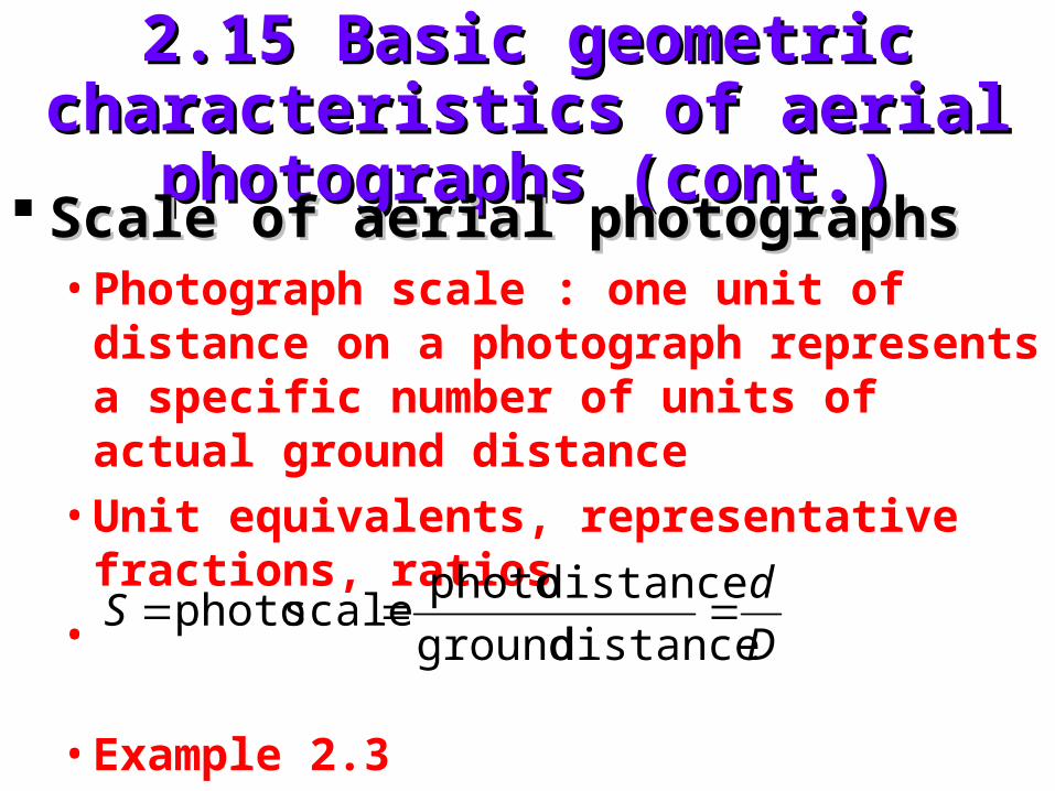
Scale of aerial photographsScale of aerial photographs• Photograph scale : one unit of distance on a
photograph represents a specific number of units of actual ground distance
• Unit equivalents, representative fractions, ratios
•
• Example 2.3
D
dS
distance ground
distance photoscale photo
2.15 Basic geometric characteristics 2.15 Basic geometric characteristics of aerial photographs (cont.)of aerial photographs (cont.)
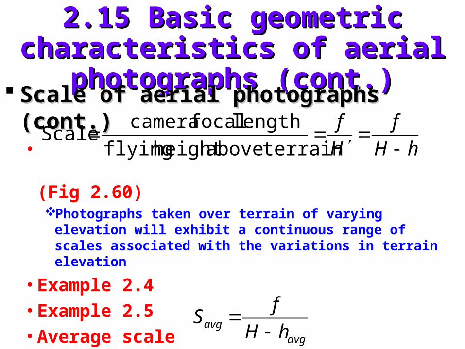
Scale of aerial photographs (cont.)Scale of aerial photographs (cont.)•
(Fig 2.60)Photographs taken over terrain of varying elevation will
exhibit a continuous range of scales associated with the variations in terrain elevation
• Example 2.4
• Example 2.5
• Average scale
hH
f
H
f
terrainaboveheight flying
length focal cameraScale
avgavg hH
fS

2.15 Basic geometric characteristics 2.15 Basic geometric characteristics of aerial photographs (cont.)of aerial photographs (cont.)
Comparative geometry of map & vertical Comparative geometry of map & vertical aerial photographaerial photograph• Map orthographic projection map position• Vertical photograph perspective projection
relative horizontal (planimetric)positionsFig 2.61
• Relief displacement: tops of objects are always displaced from their bases, this distortion is hobject 1/H’ radial distance from the principal pointAerial photographs (not directly) map (chap 4)
• Ground coveragefn(camera format size, focal length, H’)Fig 2.62

2.16 Photographic resolution2.16 Photographic resolution
Spatial resolution:Spatial resolution:an expression of the optical quality of an image produced
by a particular camera system
• Influenced byResolving power of filmCamera lensUncompensated image motionAtmospheric conditionFilm processing condition
• Fig 2.63: resolving power test chart

2.16 Photographic resolution (cont.)2.16 Photographic resolution (cont.)
Resolving power of the film (lines/mm)Resolving power of the film (lines/mm)• The reciprocal of the center-to-center distance
(mm) of the lines that are just “distinguishable” in the test chart
Contrast
2.16 Photographic resolution (cont.)2.16 Photographic resolution (cont.)
Modulation transfer functionModulation transfer function• A microdensitometer is used to scan across images of
a series of “square wave” test patterns (Fig 2.64)• Spatial frequency modulation transfer function• Complete curve (Fig 2.65)• A “trade-off” between “speed” & “resolution”• Dynamical spatial resolution of the total system• Detection recognition identification• Ground resolution distance
resolution system
scale image of reciprocalGRD

2.17 Conclusion2.17 Conclusion
Aerial photographyAerial photography• Backbone of remote sensing
• Pros
• Cons & limitations
Trend Trend digital recordingdigital recording
Related Documents