Level 2 Chapter 17 Special Application Equipment

Welcome message from author
This document is posted to help you gain knowledge. Please leave a comment to let me know what you think about it! Share it to your friends and learn new things together.
Transcript
Level 2
Chapter 17 Special Application Equipment
Special Application Equipment 17:1
Coating Inspector Program Level 2 © NACE International, 2004 January 2007
Special Application Equipment
Introduction
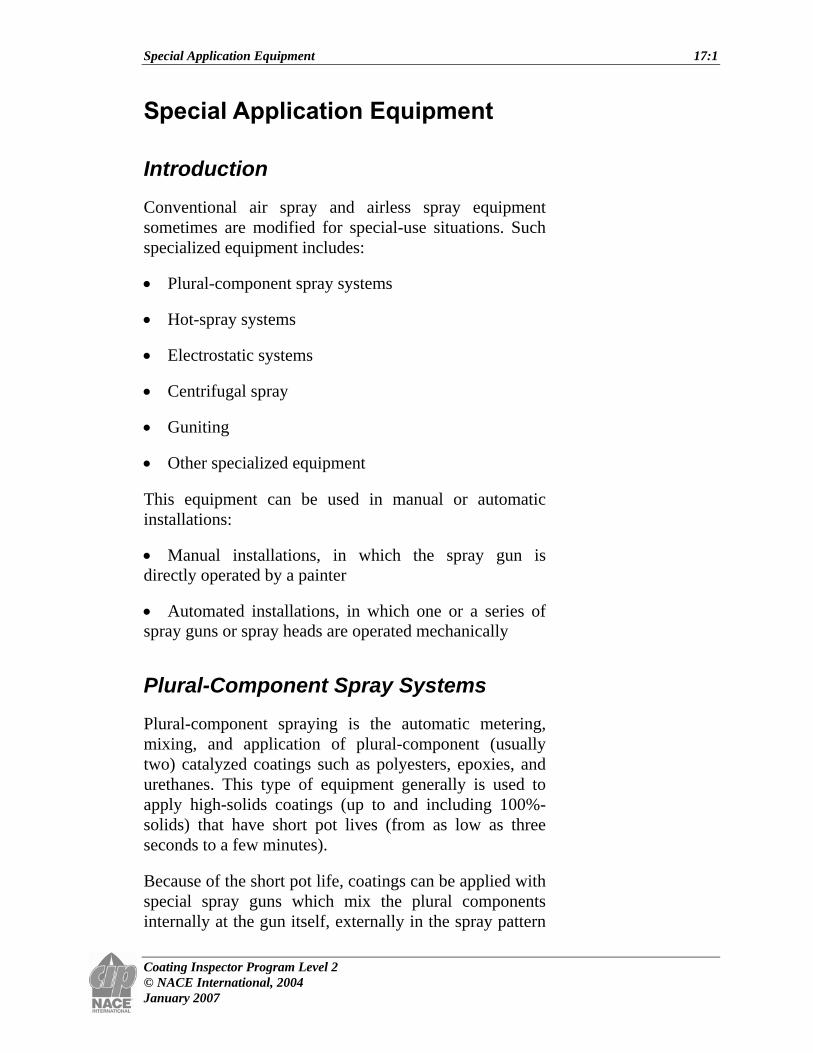
Conventional air spray and airless spray equipment sometimes are modified for special-use situations. Such specialized equipment includes:
• Plural-component spray systems
• Hot-spray systems
• Electrostatic systems
• Centrifugal spray
• Guniting
• Other specialized equipment
This equipment can be used in manual or automatic installations:
• Manual installations, in which the spray gun is directly operated by a painter
• Automated installations, in which one or a series of spray guns or spray heads are operated mechanically
Plural-Component Spray Systems
Plural-component spraying is the automatic metering, mixing, and application of plural-component (usually two) catalyzed coatings such as polyesters, epoxies, and urethanes. This type of equipment generally is used to apply high-solids coatings (up to and including 100%-solids) that have short pot lives (from as low as three seconds to a few minutes).
Because of the short pot life, coatings can be applied with special spray guns which mix the plural components internally at the gun itself, externally in the spray pattern
Special Application Equipment 17:2
Coating Inspector Program Level 2 © NACE International, 2004 January 2007
in front of the gun, or through the use of a manifold mixer installed inline before the spray gun.
Plural-component spray is used for several reasons, including:
• Ease of applying very high-solids materials which meet or exceed the requirements of environmental regulations limiting solvent emissions Volatile Organic Compound (VOC) regulations.
• Ease of applying 100%-solids materials which may have special performance characteristics for use on steel or concrete at 500 µm (20 mils) or more per coat.
• Efficiency of spraying in continuous operation, multiple-component materials that may not require an induction or sweat-in time.
Perhaps the major advantage of using plural-component spray systems is with materials such as the polyureas, which have a very short pot life (usually less than 10 seconds) and cannot be mixed in an open container prior to application.
These short-pot-life materials, along with regular plural-component epoxies, urethanes, etc., are blended and mixed within the system, not exposed to the atmosphere, and delivered in a proper ratio to the work piece. This process provides great savings in materials usage and reduces the problems and/or costs associated with waste disposal.
Equipment
Plural-component spray equipment is either:
• A fixed-ratio type, or
• A variable-ratio type
The fixed-ratio type can deliver only one volume of the plural component in a ratio such as 1:1. A variable-ratio

Special Application Equipment 17:3
Coating Inspector Program Level 2 © NACE International, 2004 January 2007
system can be adjusted to such proportioning ratios as 1:1 to 18:1 or greater.
Figure 17.1: Portable Plural-Component Spray Outfit
The equipment consists of two or three airless pumps attached to an air motor. Individual pumps deliver separate components from containers to the air motor that delivers metered material through separate lines to:
• A spray gun for delivery, or
• A mixing manifold equipped with static or mechanical mixers; the blended material then passes through a short whip hose 2 to 3 m (8 to 15 ft) long to the spray gun
With the fixed-ratio unit, the pumps are set to deliver equal volumes of the separate components, while the variable-ratio units are equipped with a master pump and a slave pump. The master pump delivers the resin, and the slave pump dispenses the catalyst (activator).
The slave pump is fitted onto a sliding bar that allows it to move forward and backward, and the position of the pump on the bar changes the length of the pump stroke. A short stroke of the pump provides less catalyst, a longer
Special Application Equipment 17:4
Coating Inspector Program Level 2 © NACE International, 2004 January 2007
stroke provides more catalyst; thus, the catalyst-to-resin ratio can be varied.
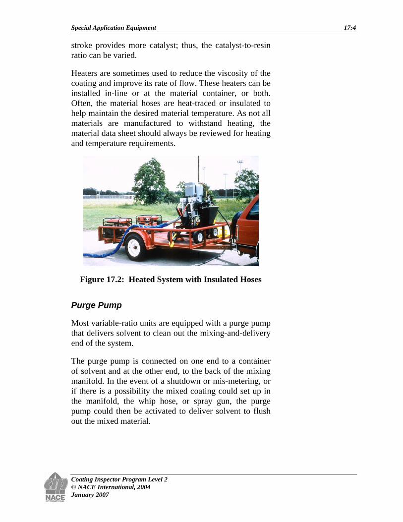
Heaters are sometimes used to reduce the viscosity of the coating and improve its rate of flow. These heaters can be installed in-line or at the material container, or both. Often, the material hoses are heat-traced or insulated to help maintain the desired material temperature. As not all materials are manufactured to withstand heating, the material data sheet should always be reviewed for heating and temperature requirements.
Figure 17.2: Heated System with Insulated Hoses
Purge Pump
Most variable-ratio units are equipped with a purge pump that delivers solvent to clean out the mixing-and-delivery end of the system.
The purge pump is connected on one end to a container of solvent and at the other end, to the back of the mixing manifold. In the event of a shutdown or mis-metering, or if there is a possibility the mixed coating could set up in the manifold, the whip hose, or spray gun, the purge pump could then be activated to deliver solvent to flush out the mixed material.
Special Application Equipment 17:5
Coating Inspector Program Level 2 © NACE International, 2004 January 2007
Plural-Component Spray Guns
Plural-component spray guns are available for either conventional air spray or airless spray applications.
The materials are mixed:
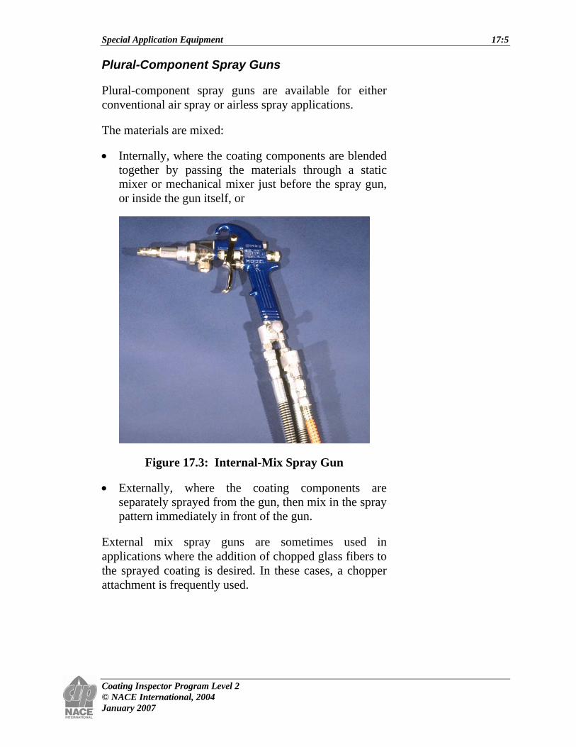
• Internally, where the coating components are blended together by passing the materials through a static mixer or mechanical mixer just before the spray gun, or inside the gun itself, or
Figure 17.3: Internal-Mix Spray Gun
• Externally, where the coating components are separately sprayed from the gun, then mix in the spray pattern immediately in front of the gun.
External mix spray guns are sometimes used in applications where the addition of chopped glass fibers to the sprayed coating is desired. In these cases, a chopper attachment is frequently used.

Special Application Equipment 17:6
Coating Inspector Program Level 2 © NACE International, 2004 January 2007
Figure 17.4: External-Mix Gun with Glass Chopper
The chopper unit is usually air powered and attached to the top of the gun. A glass-fiber rope, called roving, is fed into the chopper, where it is chopped into shreds of the desired length, and then propelled into the spray pattern of the coating. The blended mixture of glass fibers and the coating is then delivered to the surface being coated. This glass fiber/coating system is usually over coated by a gel coat of the coating resin without the glass fiber. The gel coat can be applied by a conventional spray unit or by an airless system.
Manifold Mixing System
In a manifold mixing system, the coating components are drawn from their containers, brought together in a manifold, mixed, and then delivered to the spray gun or spray head for spraying.
These manifolds usually contain a static in-line mixer like the one shown here, which is used in a feed line before it enters the gun. These mixers work by cutting the coating stream in half and turning it 90°. This is done numerous times such that the components are mixed thoroughly when they exit the spray gun.

Special Application Equipment 17:7
Coating Inspector Program Level 2 © NACE International, 2004 January 2007
Figure 17.5: Static Mixer for Manifold Mixing System
Figure 17.6: Mixing Block for Plural-Component Spray Unit with Insulated Hoses
These mixing devices can be used with either conventional air spray or airless spray and are used more commonly for high-viscosity materials. In some manifolds, the ratio or proportion in which the separate coating components are mixed can vary from 1:1 to 18:1 or greater.
Manifold mixing systems are used in field coating applications, as well as in coating shops. Many of the 100%-solids elastomeric and epoxy coatings used for secondary containment are applied with plural-component spray equipment.

Special Application Equipment 17:8
Coating Inspector Program Level 2 © NACE International, 2004 January 2007
Hot-Spray Systems
Heating the coating liquid prior to application is used in air spray and airless spray applications. It is accomplished by either the use of an in-line heater, or a hot box, which heats the coating before it is passed through the spray gun.
The increased temperature of the liquid generally reduces viscosity, allowing the coatings to be applied at a somewhat faster rate. Also, as the coating is propelled into the air, it cools rapidly and viscosity increases shortly after the coating hits the surface. This helps the coating remain in place and reduces sags and curtains, making a more uniform film.
Heating coatings formulated for hot application also allows higher-solids and higher-viscosity materials to be sprayed more efficiently, permitting thicker coats of material to be applied without runs or sags.
When heaters are used, the coating must not be heated to a temperature higher than allowed by the specification or recommended by the manufacturer.
In-Line Coating Heaters
Coating heaters come in a number of sizes, shapes, and forms. They generally preheat the coating to temperatures ranging from 35°C (95°F) to 93°C (200°F).
Some heaters are portable and may be attached to the spray man’s belt; those being electric require a cord. Along with the weight of the heater itself, this makes the equipment somewhat more cumbersome and may create a safety issue for the painter.
The coating may also pass through a stationary heater situated between the pump and the gun. The in-line heaters mounted on the pump are 4,000-watt, thermostatically controlled units that can heat either component to 70°C (158°F). Even with such heaters, there can be considerable heat loss with this method,
Special Application Equipment 17:9
Coating Inspector Program Level 2 © NACE International, 2004 January 2007
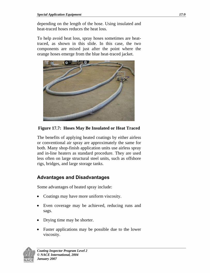
depending on the length of the hose. Using insulated and heat-traced hoses reduces the heat loss.
To help avoid heat loss, spray hoses sometimes are heat-traced, as shown in this slide. In this case, the two components are mixed just after the point where the orange hoses emerge from the blue heat-traced jacket.
Figure 17.7: Hoses May Be Insulated or Heat Traced
The benefits of applying heated coatings by either airless or conventional air spray are approximately the same for both. Many shop-finish application units use airless spray and in-line heaters as standard procedure. They are used less often on large structural steel units, such as offshore rigs, bridges, and large storage tanks.
Advantages and Disadvantages
Some advantages of heated spray include:
• Coatings may have more uniform viscosity.
• Even coverage may be achieved, reducing runs and sags.
• Drying time may be shorter.
• Faster applications may be possible due to the lower viscosity.

Special Application Equipment 17:10
Coating Inspector Program Level 2 © NACE International, 2004 January 2007
• Coatings can be sprayed readily at lower ambient temperatures.
• There may be less solvent fumes because no solvents are added.
• Coating thickness may increase per unit of application.
• Finer atomization with lower application pressures may be possible.
• Coating adhesion may be improved with reduced viscosity.
• Longer lengths of hose, if required, may be used.
Figure 17.8: Men Spraying Pipe with Heated Material

Special Application Equipment 17:11
Coating Inspector Program Level 2 © NACE International, 2004 January 2007
The major disadvantage of heated spray is that the coating may be damaged by incorrect heating.
Also, poor mixing ratios can result if the equipment metering devices fail, or are not set properly.
Electrostatic Spray
Electrostatic spray may be used with either conventional air spray, airless, or air-assisted airless spray equipment, in manual or automatic settings.
Figure 17.9: Electrostatic Spray Gun
In electrostatic spray operations:
• A rather high charge (to 75 KV for hand-held guns; to 180 KV for some automated setups) is applied to the coating particles as they pass away from the spray gun.
• The coating particles are given an electrical charge, and the work piece is grounded. The charge on the particle may be positive or negative, but is more often positive.
• When the charged coating passes through the spray gun and into the air, the opposite charges attract each other; and the finely divided coating is attracted to all sides, edges, outside corners, and some recesses of the object being coated.

Special Application Equipment 17:12
Coating Inspector Program Level 2 © NACE International, 2004 January 2007
G?
+
+
?+
+++
+
+
G?
+
+
?+
+++
+
+
Figure 17.10: Electrostatic Spray with Positive Charge on Coating and Negative Charge on Object
• The opposite side of the object may be coated if the distance the coating must travel is not too far from the spray gun.
Generally, most of the coating arrives on the surface to be coated with very little loss. This means good transfer efficiency.
Electrostatic spray application is ideally suited for application in plant production finishing. It is not as suitable for maintenance coatings, or for high-performance coatings on complex structures.
Figure 17.11: Electrostatic Spray in Booth
Special Application Equipment 17:13
Coating Inspector Program Level 2 © NACE International, 2004 January 2007
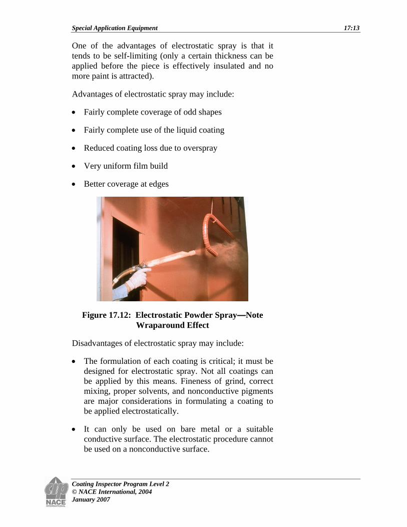
One of the advantages of electrostatic spray is that it tends to be self-limiting (only a certain thickness can be applied before the piece is effectively insulated and no more paint is attracted).
Advantages of electrostatic spray may include:
• Fairly complete coverage of odd shapes
• Fairly complete use of the liquid coating
• Reduced coating loss due to overspray
• Very uniform film build
• Better coverage at edges
Figure 17.12: Electrostatic Powder Spray—Note Wraparound Effect
Disadvantages of electrostatic spray may include:
• The formulation of each coating is critical; it must be designed for electrostatic spray. Not all coatings can be applied by this means. Fineness of grind, correct mixing, proper solvents, and nonconductive pigments are major considerations in formulating a coating to be applied electrostatically.
• It can only be used on bare metal or a suitable conductive surface. The electrostatic procedure cannot be used on a nonconductive surface.

Special Application Equipment 17:14
Coating Inspector Program Level 2 © NACE International, 2004 January 2007
• Usually, only one coat of the material is applied electrostatically because of the insulating characteristics of the original material. Newer technologies now allow for the application of more than one coat under certain circumstances.
• The equipment is more expensive than comparable conventional air or airless spray setups.
• Because of the very high voltage used, there is a safety hazard of electrical shock during application.
Safety Features
Regarding safety, the newer solid-state power units are more efficient than the conventional-type units and are much safer to operate.
Many of these units feature variable voltage settings from 0 to 75,000 V, with “fold-back” circuitry which automatically reduces the voltage of the power supply to a level that is not hazardous if 95- to 100-mA (mA = 1/1000 Amp) current levels are exceeded.
Variable voltage settings are more efficient and allow for variations in the conductivity of the material being sprayed and the distance from the spray gun to the object.
Detectors monitor the current output and reduce the voltage in the event of a sudden rise in the output current. If an object rapidly approaches the spray apparatus, the detection system can “sense” the sudden change and prevent a dangerous discharge.
Most of these power units will immediately de-energize if the system somehow exceeds 128 μA. This prevents any current discharge in the event of a failure, such as a cable fracture or breakage of the spray apparatus. It functions similar to a fuse in a circuit.
To ensure maximum safety, a ground-sensing circuit prevents the power supply from operating if the “third-wire” ground is not satisfactory.

Special Application Equipment 17:15
Coating Inspector Program Level 2 © NACE International, 2004 January 2007
In operation, a separate power supply generally is used for each gun to restrict voltage control of the spray gun exclusively to the operator of the gun.
Centrifugal Spray
Centrifugal spray equipment uses a rapidly spinning disc, brush, or other device to atomize the coating.
Figure 17.13: Centrifugal Spray
Centrifugal spray equipment may be used with or without electrostatic charge.
This type of equipment is used widely in lining pipe in specialized shop operations.
Guniting
Gunite and guniting are terms originally registered and/or trademarked by the Allentown Pump and Gun Company of Pennsylvania. This company manufactures equipment for delivering cementitious products to concrete or metal

Special Application Equipment 17:16
Coating Inspector Program Level 2 © NACE International, 2004 January 2007
surfaces with compressed air, rather than by troweling or casting in place.
Figure 17.14: Guniting
Figure 17.15: Guniting Equipment
Special Application Equipment 17:17
Coating Inspector Program Level 2 © NACE International, 2004 January 2007
The trademarks have expired, and now the terms gunite and guniting are generic designations for the air delivery system for applying cementitious coatings.
The American Concrete Institute (ACI) has since defined the product being applied as either dry shotcrete or wet shotcrete, and these terms are generally accepted in industry.
Some applicators still regard gunite as the dry product and shotcrete as the wet product. The ACI designation will be used in this course.
Application
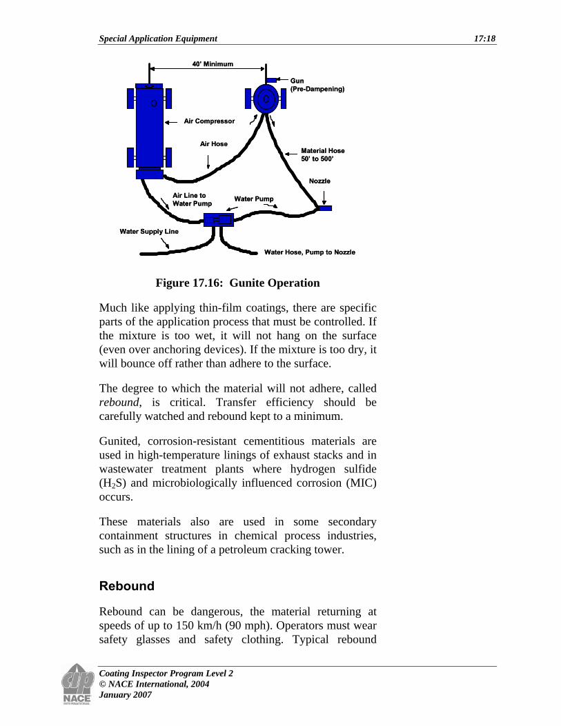
In the guniting process, dry mixtures of shotcrete are pre-dampened when they are first introduced into the system at the gun (see schematic); and as they are propelled through the hose, a wetting agent (usually water) is added to the dampened powder at the nozzle.
The nozzle consists of a brass body and ring. The mixture is propelled through the nozzle and adheres to the surface. Adjustments to the amount of liquid are critical and require a skilled operator. Typical liquid content may fall in the range of 6 to 7%. In general, the gunited surface in the area under the stream will show a silky, glistening sheen if the mix ratios are correct; a rippling, wet one if the shotcrete is too wet; and an expanding granular one if it is too dry. Sometimes a gelling agent may be added to the mixture. This helps bind the materials together for better bond to the substrate. For corrosion-resistant materials, the liquid may be a special formulation called a binder.
Specified thicknesses of the gunited material vary depending on the application. Most systems for corrosion applications have a minimum thickness of 38 mm (1.5 in.). If shotcrete is used to replace deteriorated concrete, as much as 9 to 25 cm (6 to 10 in.) of the material may be applied to bring the surface up to the original grade.
Special Application Equipment 17:18
Coating Inspector Program Level 2 © NACE International, 2004 January 2007
Air Hose
Air Compressor
Water Pump
Material Hose50’ to 500’
Nozzle
Gun(Pre-Dampening)
40’ Minimum
Air Line toWater Pump
Water Hose, Pump to Nozzle
Water Supply Line
Air Hose
Air Compressor
Water Pump
Material Hose50’ to 500’
Nozzle
Gun(Pre-Dampening)
40’ Minimum
Air Line toWater Pump
Water Hose, Pump to Nozzle
Water Supply Line
Air Hose
Air Compressor
Water Pump
Material Hose50’ to 500’
Nozzle
Gun(Pre-Dampening)
40’ Minimum
Air Line toWater Pump
Water Hose, Pump to Nozzle
Water Supply Line
Figure 17.16: Gunite Operation
Much like applying thin-film coatings, there are specific parts of the application process that must be controlled. If the mixture is too wet, it will not hang on the surface (even over anchoring devices). If the mixture is too dry, it will bounce off rather than adhere to the surface.
The degree to which the material will not adhere, called rebound, is critical. Transfer efficiency should be carefully watched and rebound kept to a minimum.
Gunited, corrosion-resistant cementitious materials are used in high-temperature linings of exhaust stacks and in wastewater treatment plants where hydrogen sulfide (H2S) and microbiologically influenced corrosion (MIC) occurs.
These materials also are used in some secondary containment structures in chemical process industries, such as in the lining of a petroleum cracking tower.
Rebound
Rebound can be dangerous, the material returning at speeds of up to 150 km/h (90 mph). Operators must wear safety glasses and safety clothing. Typical rebound
Special Application Equipment 17:19
Coating Inspector Program Level 2 © NACE International, 2004 January 2007
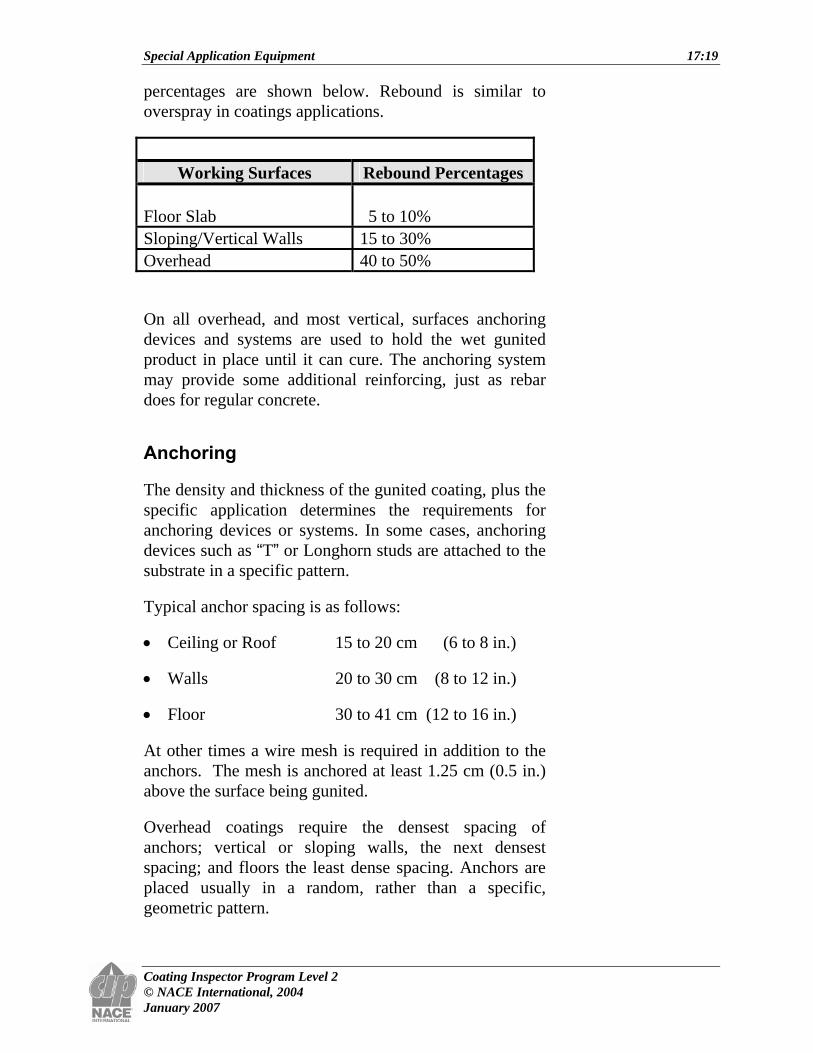
percentages are shown below. Rebound is similar to overspray in coatings applications.
Working Surfaces Rebound Percentages
Floor Slab
5 to 10%
Sloping/Vertical Walls 15 to 30% Overhead 40 to 50%
On all overhead, and most vertical, surfaces anchoring devices and systems are used to hold the wet gunited product in place until it can cure. The anchoring system may provide some additional reinforcing, just as rebar does for regular concrete.
Anchoring
The density and thickness of the gunited coating, plus the specific application determines the requirements for anchoring devices or systems. In some cases, anchoring devices such as “T” or Longhorn studs are attached to the substrate in a specific pattern.
Typical anchor spacing is as follows:
• Ceiling or Roof 15 to 20 cm (6 to 8 in.)
• Walls 20 to 30 cm (8 to 12 in.)
• Floor 30 to 41 cm (12 to 16 in.)
At other times a wire mesh is required in addition to the anchors. The mesh is anchored at least 1.25 cm (0.5 in.) above the surface being gunited.
Overhead coatings require the densest spacing of anchors; vertical or sloping walls, the next densest spacing; and floors the least dense spacing. Anchors are placed usually in a random, rather than a specific, geometric pattern.

Special Application Equipment 17:20
Coating Inspector Program Level 2 © NACE International, 2004 January 2007
Figure 17.17: Anchoring
When a membrane is used in conjunction with the system, the anchoring system should be installed first, then coated with the membrane. Membranes are discussed in more detail in the section on special coatings.
Gunited products are applied from the ground up to prevent application over rebound that may have fallen onto the surface.
The inspector must pay particular attention to:
• Surface preparation
• Equipment
• Rebound
Special Application Equipment 17:21
Coating Inspector Program Level 2 © NACE International, 2004 January 2007
Gunite System Advantages
The gunite process offers certain advantages over brick/mortar and cast/troweled systems. For example:
• Application is 5 to 10 times faster.
• The product is seamless and improves protection.
• The material covers complex configurations.
• Applications can be made year-round.
• The product has good insulation qualities.
• The process is economical.
• The process offers long-term protection.
The guniting process also has some disadvantages:
• The process is wind sensitive and cannot be applied even in a slight breeze.
• Application requires a five-man crew.
• Application requires bulky equipment.
Other Specialized Equipment
High-Volume Low-Pressure Spray Systems
High-volume low-pressure (HVLP) spray systems use a high volume of air delivered at 69 kPa (10 psi) or less to atomize a fluid coating into a soft low-velocity pattern. This reduction in the air stream, compared with the 243 to 283 kPa (40 to 70 psi) typically delivered by conventional air spray methods, results in:
• A more controlled spray pattern
• Reduced bounce back
• Reduced overspray
Special Application Equipment 17:22
Coating Inspector Program Level 2 © NACE International, 2004 January 2007
• Reduced VOC emissions
• Savings in materials usage
• Less hazardous waste
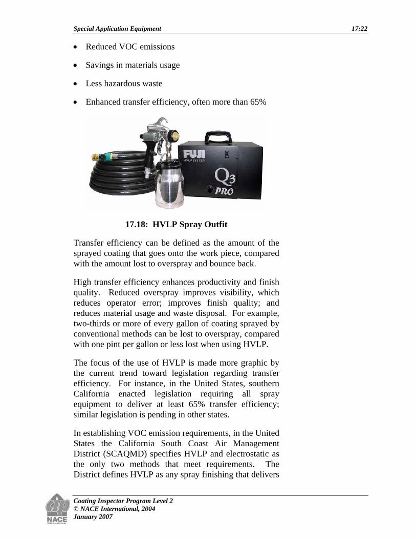
• Enhanced transfer efficiency, often more than 65%
17.18: HVLP Spray Outfit
Transfer efficiency can be defined as the amount of the sprayed coating that goes onto the work piece, compared with the amount lost to overspray and bounce back.
High transfer efficiency enhances productivity and finish quality. Reduced overspray improves visibility, which reduces operator error; improves finish quality; and reduces material usage and waste disposal. For example, two-thirds or more of every gallon of coating sprayed by conventional methods can be lost to overspray, compared with one pint per gallon or less lost when using HVLP.
The focus of the use of HVLP is made more graphic by the current trend toward legislation regarding transfer efficiency. For instance, in the United States, southern California enacted legislation requiring all spray equipment to deliver at least 65% transfer efficiency; similar legislation is pending in other states.
In establishing VOC emission requirements, in the United States the California South Coast Air Management District (SCAQMD) specifies HVLP and electrostatic as the only two methods that meet requirements. The District defines HVLP as any spray finishing that delivers
Special Application Equipment 17:23
Coating Inspector Program Level 2 © NACE International, 2004 January 2007
air-operating pressure of 0.69 to 69 kPa (0.1 to 10 psi) at the air cap. (Note: It is believed that some other systems have been modified to meet this requirement. These modified units utilize a low-pressure airless pump and a modified version of an air-assisted airless gun.)
HVLP generally is compared to a conventional air spray system. Both use compressed air for atomization. The major difference is that HVLP is limited to a maximum of 69 kPa (10 psi). Conventional air spray is limited only by the available air supply; pressures of 345 to 414 kPa (40 to 70 psi) or higher are common in conventional air spray systems.
An HVLP system consists of a material supply, a source of high-volume air, and special guns that control the air atomization pressure to kPa (psi) maximum. Special air caps and tips ensure proper atomization.
In general, HVLP can be used with most low- to medium-solids materials such as two-component epoxies, urethanes, acrylics, enamels, lacquers, stains, etc.
Air-Assisted Airless Spray
Air-assisted airless technology combines the best features of air spray and airless spray to create a new spray finishing capability.
Conventional air spray produces a very high quality finish, but uses large volumes of air (8 to 30 cfm). The turbulence generated by air spray can create excessive overspray, resulting in a loss of materials and a lower transfer efficiency.
Airless spray minimizes overspray and improves transfer efficiency, using high fluid pressure to force the coating through a small orifice to achieve atomization.
Special Application Equipment 17:24
Coating Inspector Program Level 2 © NACE International, 2004 January 2007
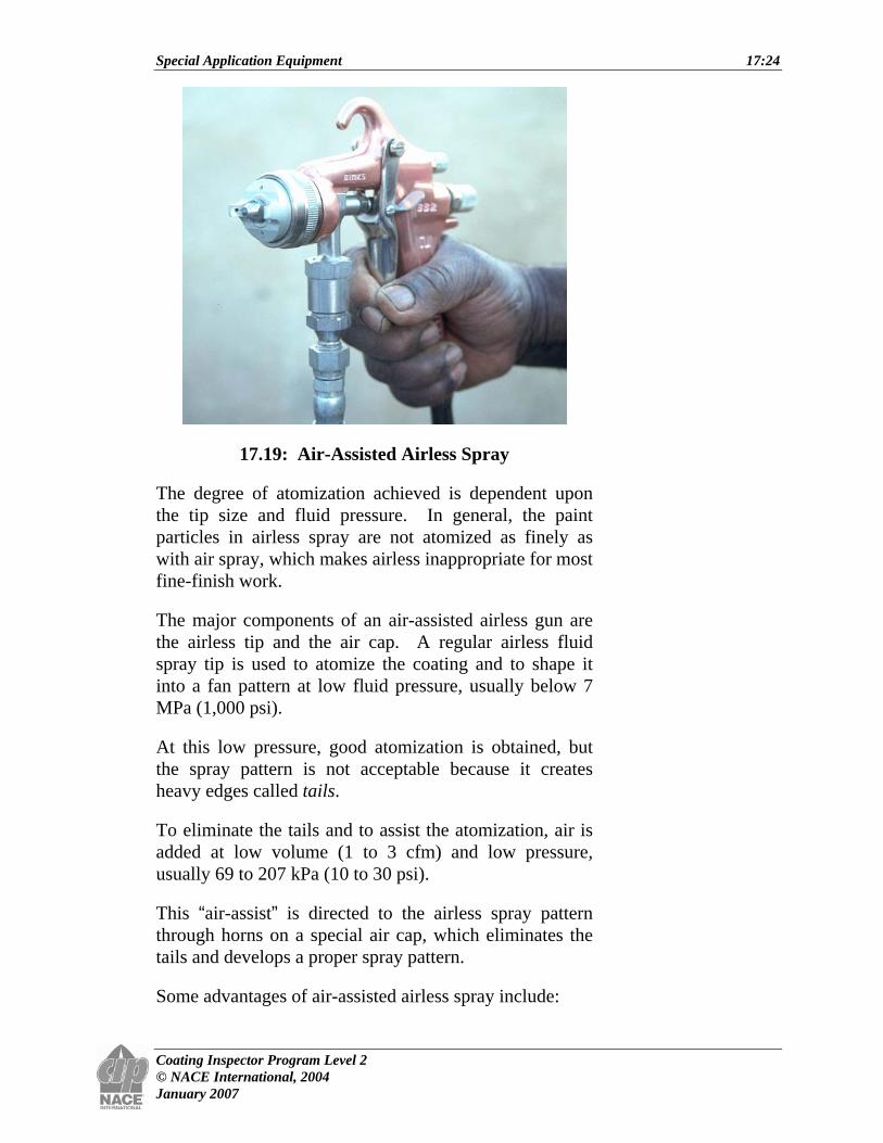
17.19: Air-Assisted Airless Spray
The degree of atomization achieved is dependent upon the tip size and fluid pressure. In general, the paint particles in airless spray are not atomized as finely as with air spray, which makes airless inappropriate for most fine-finish work.
The major components of an air-assisted airless gun are the airless tip and the air cap. A regular airless fluid spray tip is used to atomize the coating and to shape it into a fan pattern at low fluid pressure, usually below 7 MPa (1,000 psi).
At this low pressure, good atomization is obtained, but the spray pattern is not acceptable because it creates heavy edges called tails.
To eliminate the tails and to assist the atomization, air is added at low volume (1 to 3 cfm) and low pressure, usually 69 to 207 kPa (10 to 30 psi).
This “air-assist” is directed to the airless spray pattern through horns on a special air cap, which eliminates the tails and develops a proper spray pattern.
Some advantages of air-assisted airless spray include:

Special Application Equipment 17:25
Coating Inspector Program Level 2 © NACE International, 2004 January 2007
• Good finish appearance
• Excellent transfer efficiency (30 to 35% better than air spray)
• Wide range of fluid flow rates (0.15 to 1.5 L/min [5 to 50 fl. oz/min])
• Reduced overspray
• Less tip wear and longer pump life due to lower fluid pressure compared with regular airless
• Very efficient method of atomizing liquid
Air-assisted airless spray guns have been used to apply alkyds, lacquers, catalyzed varnishes, urethanes, epoxies, water-based coatings, and zincs.
Related Documents