Etkina/Gentile/Van Heuvelen Process Physics 1/e, Chapter 15 15-1 Chapter 15: Electric Field: Force and Energy Approaches ! Why does a metal pole on the top of a building protect it from lightning? ! How does electrocardiography work? ! Why is it safe to sit in a car during a lightning storm? Make sure you know how to: 1. Find the force that one charged object exerts on another charged object. 2. Determine the electric potential energy of a system. 3. Explain the difference between the internal structure of electric conductors and dielectrics (non- conductors). Chapter opening Imagine that you are in a car during a thunderstorm. The thunder is loud; you see lightning strikes on the road just in front of you—huge compared to the sparks you see when removing clothes from the dryer. Should you be scared for your life and worried about lightning damage to the fancy electronics in your car? The frame of the car is made of metal, which is a good electrical conductor. We will learn in this chapter why the insides of cars made of conducting material are safe places to be during a thunderstorm, even if lightning strikes the car directly. It turns out that the internal structure of conductors is what allows them to shield what is inside them from all electrostatic processes happening outside. Lead In Chapter 14 we learned how to describe the electric interaction in two ways: 1) by determining a force exerted by one charged object on another, and 2) by determining an electric potential energy possessed by pairs of charged objects. We learned that electric charge is a property of particles. When we add or remove these particles from macroscopic objects, the objects can then participate in electric interactions. We also learned that the force that these charged objects exert on each other depends on the magnitude of their charges, and also on the distance between them. Similarly, the electric potential energy possessed by pairs of charged objects depends on their charges and the distance between them. We also discovered that charged objects exert forces on each other without being in direct contact. This is only the second interaction we have encountered with this property, the gravitational interaction being the first. How does one charged object “know” about the presence of another when they are not in direct contact? We investigate this question in this chapter. 15.1 Mechanisms for the electric interaction In the previous chapter we learned that the magnitude of the force that two electrically- charged objects exert on each other is described by Coulomb’s law: 2 1 on 2 2 on 1 1 2 F F kq q r " " . Assuming that electrically charged objects (such as the electrodes of a Wimshurst generator or a

Welcome message from author
This document is posted to help you gain knowledge. Please leave a comment to let me know what you think about it! Share it to your friends and learn new things together.
Transcript
Etkina/Gentile/Van Heuvelen Process Physics 1/e, Chapter 15 15-1
Chapter 15:
Electric Field: Force and Energy Approaches
! Why does a metal pole on the top of a building protect it from lightning?
! How does electrocardiography work?
! Why is it safe to sit in a car during a lightning storm?
Make sure you know how to:
1. Find the force that one charged object exerts on another charged object.
2. Determine the electric potential energy of a system.
3. Explain the difference between the internal structure of electric conductors and dielectrics (non-
conductors).
Chapter opening Imagine that you are in a car during a thunderstorm. The thunder is loud; you
see lightning strikes on the road just in front of you—huge compared to the sparks you see when
removing clothes from the dryer. Should you be scared for your life and worried about lightning
damage to the fancy electronics in your car? The frame of the car is made of metal, which is a good
electrical conductor. We will learn in this chapter why the insides of cars made of conducting material
are safe places to be during a thunderstorm, even if lightning strikes the car directly. It turns out that
the internal structure of conductors is what allows them to shield what is inside them from all
electrostatic processes happening outside.
Lead In Chapter 14 we learned how to describe the electric interaction in two ways: 1) by
determining a force exerted by one charged object on another, and 2) by determining an electric
potential energy possessed by pairs of charged objects. We learned that electric charge is a property
of particles. When we add or remove these particles from macroscopic objects, the objects can then
participate in electric interactions. We also learned that the force that these charged objects exert on
each other depends on the magnitude of their charges, and also on the distance between them.
Similarly, the electric potential energy possessed by pairs of charged objects depends on their charges
and the distance between them. We also discovered that charged objects exert forces on each other
without being in direct contact. This is only the second interaction we have encountered with this
property, the gravitational interaction being the first. How does one charged object “know” about the
presence of another when they are not in direct contact? We investigate this question in this chapter.
15.1 Mechanisms for the electric interaction
In the previous chapter we learned that the magnitude of the force that two electrically-
charged objects exert on each other is described by Coulomb’s law: 2
1 on 2 2 on 1 1 2F F kq q r" " .
Assuming that electrically charged objects (such as the electrodes of a Wimshurst generator or a
Etkina/Gentile/Van Heuvelen Process Physics 1/e, Chapter 15 15-2
balloon that you rubbed on your hair) don’t have some sort of supernatural sense that allows them to
“see” their surroundings, how is it that they “know” to interact with other charged objects when those
other objects could be meters away? Let’s start our investigation into this phenomenon with
observational experiments.
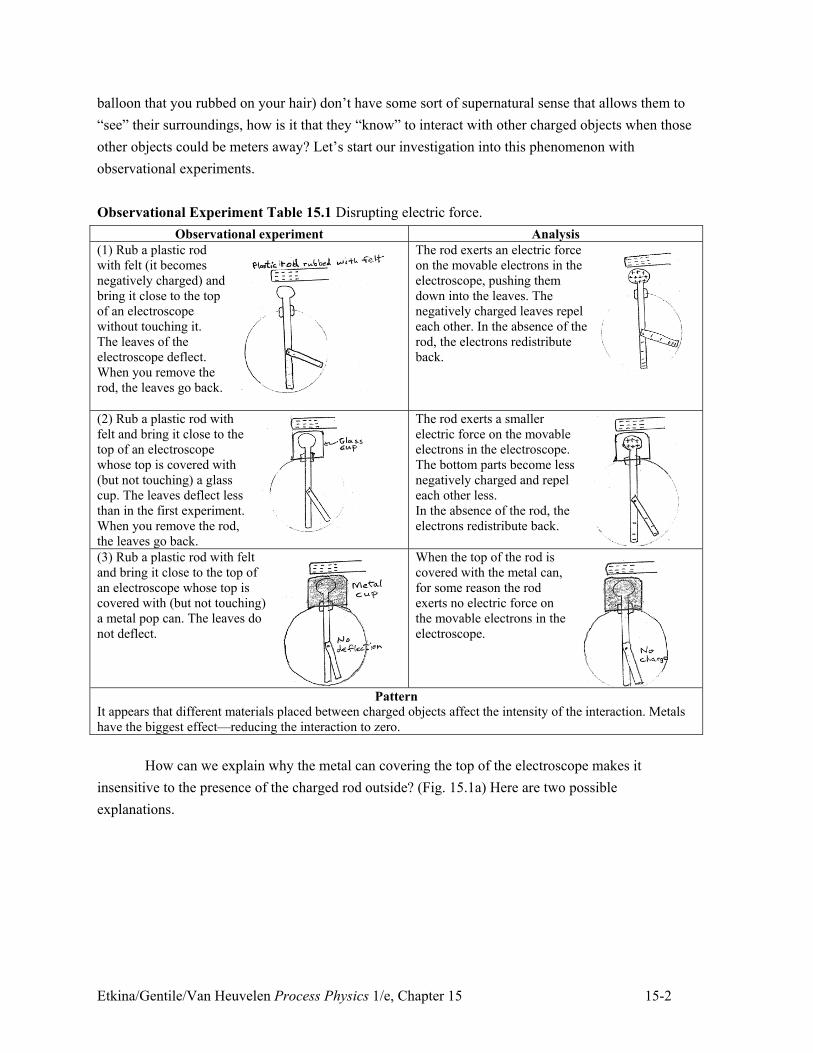
Observational Experiment Table 15.1 Disrupting electric force.
Observational experiment Analysis
(1) Rub a plastic rod
with felt (it becomes
negatively charged) and
bring it close to the top
of an electroscope
without touching it.
The leaves of the
electroscope deflect.
When you remove the
rod, the leaves go back.
The rod exerts an electric force
on the movable electrons in the
electroscope, pushing them
down into the leaves. The
negatively charged leaves repel
each other. In the absence of the
rod, the electrons redistribute
back.
(2) Rub a plastic rod with
felt and bring it close to the
top of an electroscope
whose top is covered with
(but not touching) a glass
cup. The leaves deflect less
than in the first experiment.
When you remove the rod,
the leaves go back.
The rod exerts a smaller
electric force on the movable
electrons in the electroscope.
The bottom parts become less
negatively charged and repel
each other less.
In the absence of the rod, the
electrons redistribute back.
(3) Rub a plastic rod with felt
and bring it close to the top of
an electroscope whose top is
covered with (but not touching)
a metal pop can. The leaves do
not deflect.
When the top of the rod is
covered with the metal can,
for some reason the rod
exerts no electric force on
the movable electrons in the
electroscope.
Pattern
It appears that different materials placed between charged objects affect the intensity of the interaction. Metals
have the biggest effect—reducing the interaction to zero.
How can we explain why the metal can covering the top of the electroscope makes it
insensitive to the presence of the charged rod outside? (Fig. 15.1a) Here are two possible
explanations.
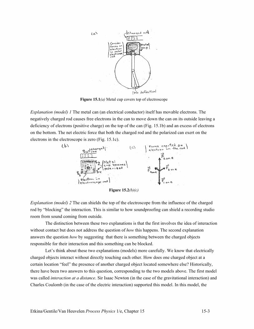
Etkina/Gentile/Van Heuvelen Process Physics 1/e, Chapter 15 15-3
Figure 15.1(a) Metal cup covers top of electroscope
Explanation (model) 1 The metal can (an electrical conductor) itself has movable electrons. The
negatively charged rod causes free electrons in the can to move down the can on its outside leaving a
deficiency of electrons (positive charge) on the top of the can (Fig. 15.1b) and an excess of electrons
on the bottom. The net electric force that both the charged rod and the polarized can exert on the
electrons in the electroscope is zero (Fig. 15.1c).
Figure 15.2(b)(c)
Explanation (model) 2 The can shields the top of the electroscope from the influence of the charged
rod by “blocking” the interaction. This is similar to how soundproofing can shield a recording studio
room from sound coming from outside.
The distinction between these two explanations is that the first involves the idea of interaction
without contact but does not address the question of how this happens. The second explanation
answers the question how by suggesting that there is something between the charged objects
responsible for their interaction and this something can be blocked.
Let’s think about these two explanations (models) more carefully. We know that electrically
charged objects interact without directly touching each other. How does one charged object at a
certain location “feel” the presence of another charged object located somewhere else? Historically,
there have been two answers to this question, corresponding to the two models above. The first model
was called interaction at a distance. Sir Isaac Newton (in the case of the gravitational interaction) and
Charles Coulomb (in the case of the electric interaction) supported this model. In this model, the
Etkina/Gentile/Van Heuvelen Process Physics 1/e, Chapter 15 15-4
electric interaction just happens. If you move one of the two interacting charges, the other charge
instantaneously “senses” that movement and responds accordingly.
Though model 1 doesn’t suggest how this interaction happens, it can explain the disruption of
the interaction between charges when a metal can surrounds one of those charges. The freely moving
electrons in the metal can rearrange themselves in the presence of the charged plastic rod on the
outside (see Fig. 15.1b and c). The electric charges present on the surface of the metal can exert an
electric force on the electrons in the electroscope that just balances the force exerted by the charged
plastic rod outside; the net electric force exerted on the electrons in the electroscope rod under the can
is zero.
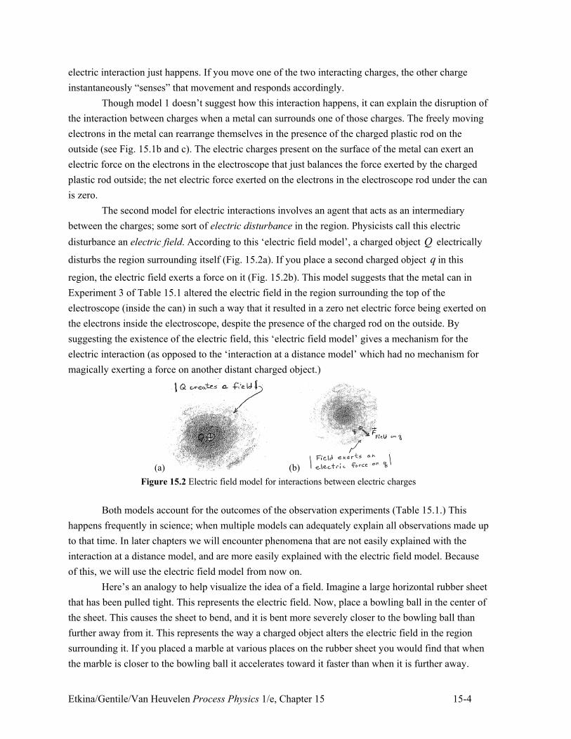
The second model for electric interactions involves an agent that acts as an intermediary
between the charges; some sort of electric disturbance in the region. Physicists call this electric
disturbance an electric field. According to this ‘electric field model’, a charged object Q electrically
disturbs the region surrounding itself (Fig. 15.2a). If you place a second charged object q in this
region, the electric field exerts a force on it (Fig. 15.2b). This model suggests that the metal can in
Experiment 3 of Table 15.1 altered the electric field in the region surrounding the top of the
electroscope (inside the can) in such a way that it resulted in a zero net electric force being exerted on
the electrons inside the electroscope, despite the presence of the charged rod on the outside. By
suggesting the existence of the electric field, this ‘electric field model’ gives a mechanism for the
electric interaction (as opposed to the ‘interaction at a distance model’ which had no mechanism for
magically exerting a force on another distant charged object.)
(a) (b)
Figure 15.2 Electric field model for interactions between electric charges
Both models account for the outcomes of the observation experiments (Table 15.1.) This
happens frequently in science; when multiple models can adequately explain all observations made up
to that time. In later chapters we will encounter phenomena that are not easily explained with the
interaction at a distance model, and are more easily explained with the electric field model. Because
of this, we will use the electric field model from now on.
Here’s an analogy to help visualize the idea of a field. Imagine a large horizontal rubber sheet
that has been pulled tight. This represents the electric field. Now, place a bowling ball in the center of
the sheet. This causes the sheet to bend, and it is bent more severely closer to the bowling ball than
further away from it. This represents the way a charged object alters the electric field in the region
surrounding it. If you placed a marble at various places on the rubber sheet you would find that when
the marble is closer to the bowling ball it accelerates toward it faster than when it is further away.
Etkina/Gentile/Van Heuvelen Process Physics 1/e, Chapter 15 15-5
This is consistent with our understanding of the electric interaction; we have learned that the electric
force that charges exert on each other is greater when the charges are closer. Notice how the rubber
sheet is acting as an intermediary, allowing the bowling ball and the marble to interact with each
other even though they are not in contact. This is analogous to the way the electric field acts as an
intermediary between charged objects, allowing them to interact even though they are not in contact
with each other.
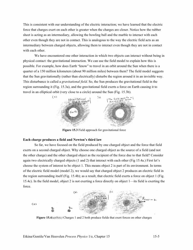
We have encountered one other interaction in which two objects can interact without being in
physical contact: the gravitational interaction. We can use the field model to explain how this is
possible. For example, how does Earth “know” to travel in an orbit around the Sun when there is a
quarter of a 150 million kilometers (about 90 million miles) between them? The field model suggests
that the Sun gravitationally (rather than electrically) disturbs the region around it in an invisible way.
This disturbance is called a gravitational field. So, the Sun produces the gravitational field in the
region surrounding it (Fig. 15.3a), and the gravitational field exerts a force on Earth causing it to
travel in an elliptical orbit (very close to a circle) around the Sun (Fig. 15.3b).
Figure 15.3 Field approach for gravitational force
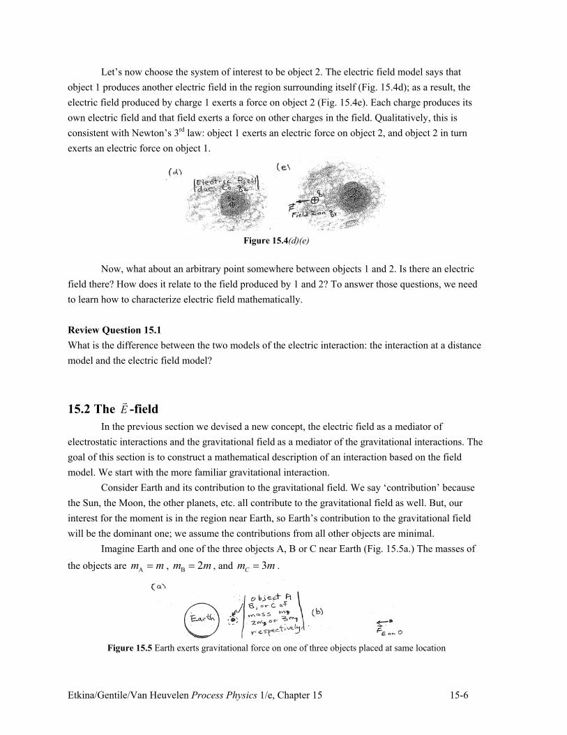
Each charge produces a field and Newton’s third law
So far, we have focused on the field produced by one charged object and the force that field
exerts on a second charged object. Why choose one charged object as the source of a field (and not
the other charge) and the other charged object as the recipient of the force due to that field? Consider
again two electrically charged objects (1 and 2) that interact with each other (Fig 15.4a.) First let’s
choose the system of interest to be object 1. This means object 2 is part of its environment. In terms
of the electric field model (model 2), we would say that charged object 2 produces an electric field in
the region surrounding itself (Fig. 15.4b); as a result, that electric field exerts a force on object 1 (Fig.
15.4c). In the field model, object 2 is not exerting a force directly on object 1—its field is exerting the
force.
Figure 15.4(a)(b)(c) Charges 1 and 2 both produce fields that exert forces on other charges
Etkina/Gentile/Van Heuvelen Process Physics 1/e, Chapter 15 15-6
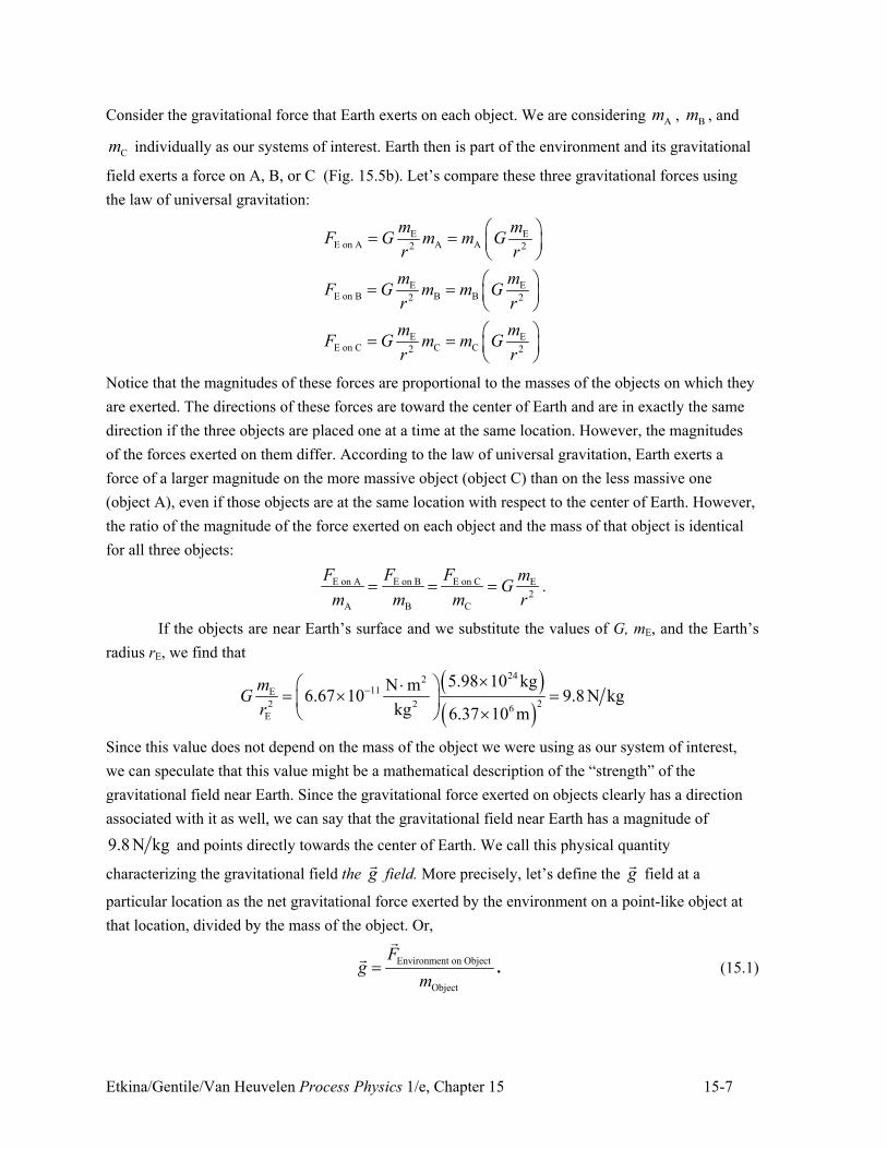
Let’s now choose the system of interest to be object 2. The electric field model says that
object 1 produces another electric field in the region surrounding itself (Fig. 15.4d); as a result, the
electric field produced by charge 1 exerts a force on object 2 (Fig. 15.4e). Each charge produces its
own electric field and that field exerts a force on other charges in the field. Qualitatively, this is
consistent with Newton’s 3rd law: object 1 exerts an electric force on object 2, and object 2 in turn
exerts an electric force on object 1.
Figure 15.4(d)(e)
Now, what about an arbitrary point somewhere between objects 1 and 2. Is there an electric
field there? How does it relate to the field produced by 1 and 2? To answer those questions, we need
to learn how to characterize electric field mathematically.
Review Question 15.1
What is the difference between the two models of the electric interaction: the interaction at a distance
model and the electric field model?
15.2 The E!
-field
In the previous section we devised a new concept, the electric field as a mediator of
electrostatic interactions and the gravitational field as a mediator of the gravitational interactions. The
goal of this section is to construct a mathematical description of an interaction based on the field
model. We start with the more familiar gravitational interaction.
Consider Earth and its contribution to the gravitational field. We say ‘contribution’ because
the Sun, the Moon, the other planets, etc. all contribute to the gravitational field as well. But, our
interest for the moment is in the region near Earth, so Earth’s contribution to the gravitational field
will be the dominant one; we assume the contributions from all other objects are minimal.
Imagine Earth and one of the three objects A, B or C near Earth (Fig. 15.5a.) The masses of
the objects are Am m" , B 2m m" , and 3Cm m" .
Figure 15.5 Earth exerts gravitational force on one of three objects placed at same location
Etkina/Gentile/Van Heuvelen Process Physics 1/e, Chapter 15 15-7
Consider the gravitational force that Earth exerts on each object. We are considering Am , Bm , and
Cm individually as our systems of interest. Earth then is part of the environment and its gravitational
field exerts a force on A, B, or C (Fig. 15.5b). Let’s compare these three gravitational forces using
the law of universal gravitation:
E EE on A A A2 2
E EE on B B B2 2
E EE on C C C2 2
m mF G m m G
r r
m mF G m m G
r r
m mF G m m G
r r
# $" " % &' (
# $" " % &' (
# $" " % &' (
Notice that the magnitudes of these forces are proportional to the masses of the objects on which they
are exerted. The directions of these forces are toward the center of Earth and are in exactly the same
direction if the three objects are placed one at a time at the same location. However, the magnitudes
of the forces exerted on them differ. According to the law of universal gravitation, Earth exerts a
force of a larger magnitude on the more massive object (object C) than on the less massive one
(object A), even if those objects are at the same location with respect to the center of Earth. However,
the ratio of the magnitude of the force exerted on each object and the mass of that object is identical
for all three objects:
E on A E on B E on C E
2
A B C
F F F mG
m m m r" " " .
If the objects are near Earth’s surface and we substitute the values of G, mE, and the Earth’s
radius rE, we find that
) *) *
24211E
22 2 6E
5.98 10 kgN m6.67 10 9.8 N kg
kg 6.37 10 m
mG
r
+,# $-
" , "% &' ( ,
Since this value does not depend on the mass of the object we were using as our system of interest,
we can speculate that this value might be a mathematical description of the “strength” of the
gravitational field near Earth. Since the gravitational force exerted on objects clearly has a direction
associated with it as well, we can say that the gravitational field near Earth has a magnitude of
9.8 N kg and points directly towards the center of Earth. We call this physical quantity
characterizing the gravitational field the g!
field. More precisely, let’s define the g!
field at a
particular location as the net gravitational force exerted by the environment on a point-like object at
that location, divided by the mass of the object. Or,
Environment on Object
Object
Fg
m"
!
!. (15.1)
Etkina/Gentile/Van Heuvelen Process Physics 1/e, Chapter 15 15-8
Tip! The gravitational field is an idea that offers an explanation for how objects not in contact with
each other can exert gravitational forces on each other. On the other hand, the g!
field is one way
(there are others) of mathematically representing the gravitational field. This makes the g!
field a
physical quantity (it has a numerical value with units), while the gravitational field is a way to help
explain the gravitational force and is not a quantity.
Electric field due to a single point-like charged object
Let’s use a similar approach to construct a physical quantity that will characterize the
“strength” of the electric field. There are a few differences though. First, it’s the electric charge of an
object (rather than its mass) that causes an electric field. Secondly, the electric charge of an object can
be positive, negative, or zero, while the mass of an object is always positive. With these differences in
mind, let’s proceed.
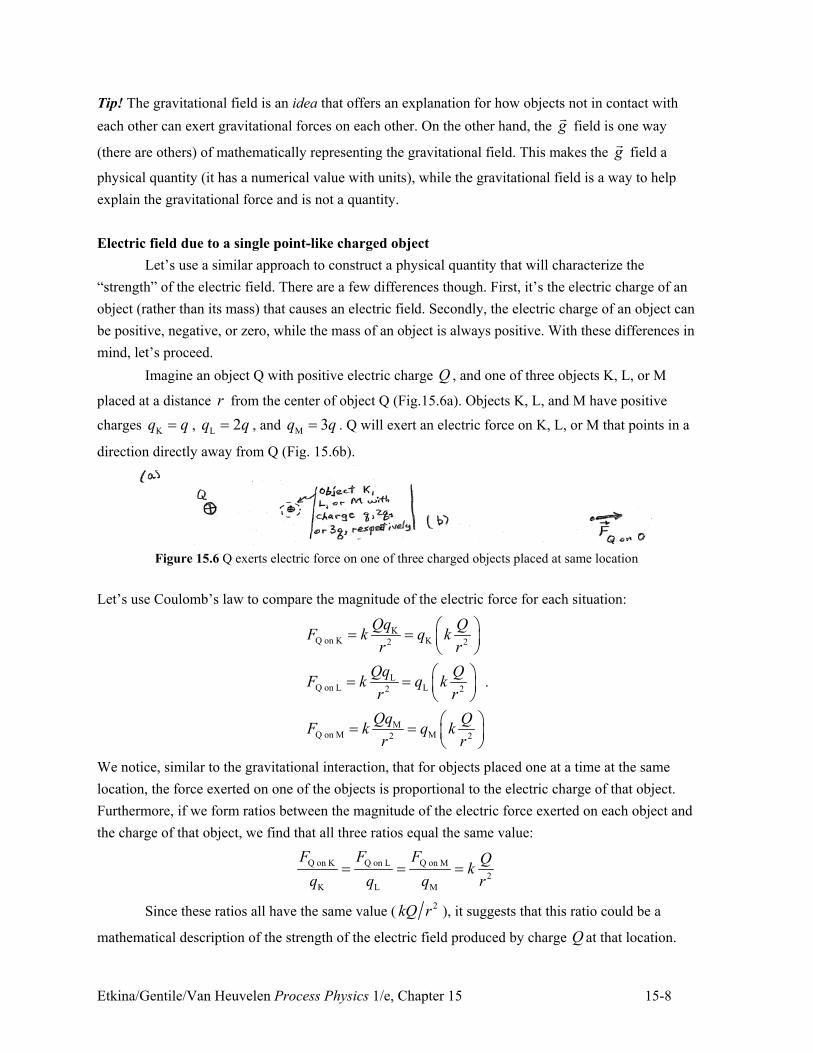
Imagine an object Q with positive electric charge Q , and one of three objects K, L, or M
placed at a distance r from the center of object Q (Fig.15.6a). Objects K, L, and M have positive
charges Kq q" , L 2q q" , and M 3q q" . Q will exert an electric force on K, L, or M that points in a
direction directly away from Q (Fig. 15.6b).
Figure 15.6 Q exerts electric force on one of three charged objects placed at same location
Let’s use Coulomb’s law to compare the magnitude of the electric force for each situation:
KQ on K K2 2
LQ on L L2 2
MQ on M M2 2
Qq QF k q k
r r
Qq QF k q k
r r
Qq QF k q k
r r
# $" " % &' (
# $" " % &' (
# $" " % &' (
.
We notice, similar to the gravitational interaction, that for objects placed one at a time at the same
location, the force exerted on one of the objects is proportional to the electric charge of that object.
Furthermore, if we form ratios between the magnitude of the electric force exerted on each object and
the charge of that object, we find that all three ratios equal the same value:
Q on K Q on L Q on M
2
K L M
F F F Qk
q q q r" " "
Since these ratios all have the same value (2kQ r ), it suggests that this ratio could be a
mathematical description of the strength of the electric field produced by charge Q at that location.
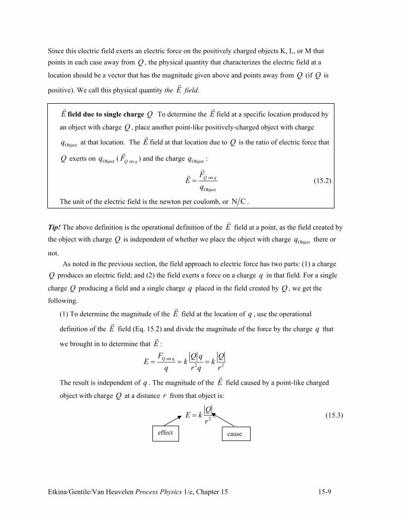
Etkina/Gentile/Van Heuvelen Process Physics 1/e, Chapter 15 15-9
Since this electric field exerts an electric force on the positively charged objects K, L, or M that
points in each case away from Q , the physical quantity that characterizes the electric field at a
location should be a vector that has the magnitude given above and points away from Q (if Q is
positive). We call this physical quantity the E!
field.
E!
field due to single charge Q To determine the E!
field at a specific location produced by
an object with charge Q , place another point-like positively-charged object with charge
Objectq at that location. The E!
field at that location due to Q is the ratio of electric force that
Q exerts on Objectq ( on Q qF!
) and the charge Objectq :
on
Object
Q qFE
q"
!!
(15.2)
The unit of the electric field is the newton per coulomb, or N C .
Tip! The above definition is the operational definition of the E!
field at a point, as the field created by
the object with charge Q is independent of whether we place the object with charge Objectq there or
not.
As noted in the previous section, the field approach to electric force has two parts: (1) a charge
Q produces an electric field; and (2) the field exerts a force on a charge q in that field. For a single
charge Q producing a field and a single charge q placed in the field created by Q , we get the
following.
(1) To determine the magnitude of the E!
field at the location of q , use the operational
definition of the E!
field (Eq. 15.2) and divide the magnitude of the force by the charge q that
we brought in to determine that E!
:
Q on q
2 2
F Q q QE k k
q r q r" " "
The result is independent of q . The magnitude of the E!
field caused by a point-like charged
object with charge Q at a distance r from that object is:
2
QE k
r" . (15.3)
cause effect
Etkina/Gentile/Van Heuvelen Process Physics 1/e, Chapter 15 15-10
The object with electric charge Q is the cause, and the E!
field produced by it is the effect.
Note also the E!
field vector points away from the object creating the field, if Q is positive and
toward it, if it has a negative charge.
(2) We say that the E!
field at a specific location is the cause of the force exerted on a point-like
object of charge q at that location. Rearranging Eq. (15.2) we can write a cause-effect relation
between the E!
field at a specific location and the force exerted on a point-like charged object q
located there:
on Q qF qE"! !
(15.4)
Expressed this way, Eq. (15.4) explains why the electric field created by the same object exerts
a larger electric force on an object with larger charge than it does on an object with smaller
electric charge. For example, if it exerts a force F!
on an object with charge q, it then will exert
a force 10F!
on an object with charge 10q .
We achieved our goal. We have a mathematical description for the magnitude of the E!
field a
distance r from a point-like charged object and know how to determine the effect of that field on
some other charge in the field. The real world is far more complex. Even in a single hydrogen atom,
there are multiple charged objects (two in this case, a single proton that makes up the nucleus and a
single electron.) How do we determine the E!
field produced by multiple point-like charged objects?
We investigate this question next.
E!
-field due to multiple charged objects
We start by considering an example that involves two charged objects and determine the
E!
field produced by those two objects at one point in space.
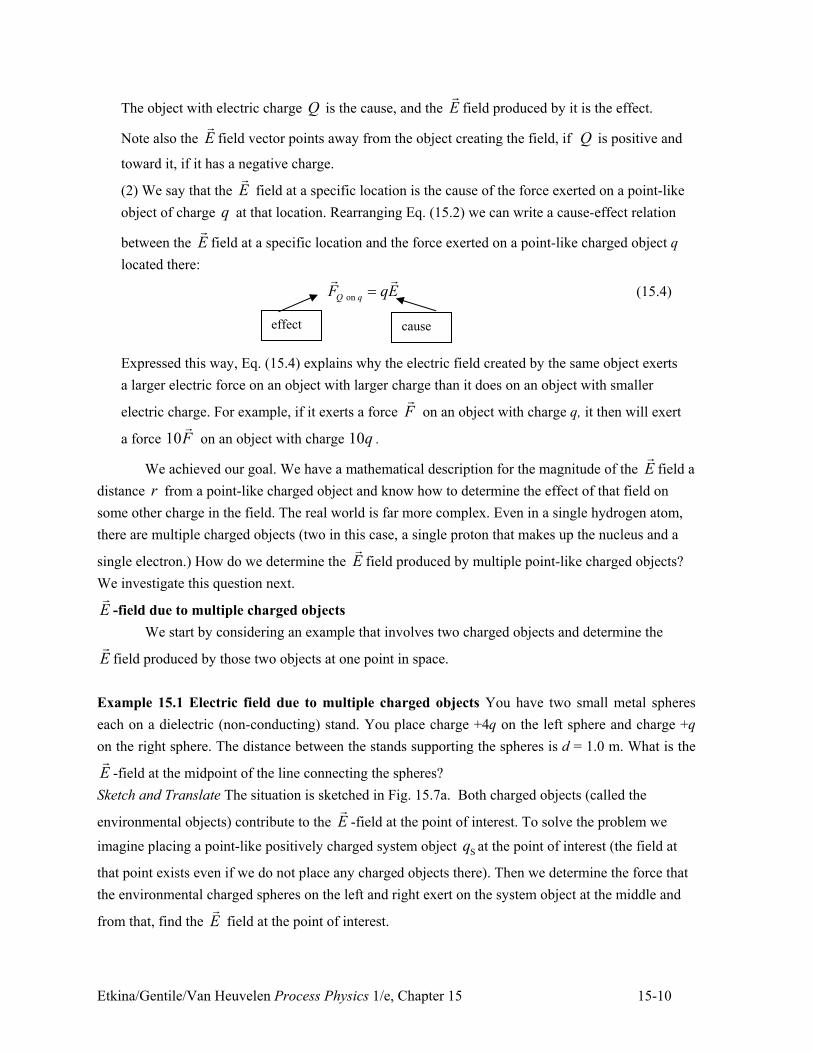
Example 15.1 Electric field due to multiple charged objects You have two small metal spheres
each on a dielectric (non-conducting) stand. You place charge +4q on the left sphere and charge +q
on the right sphere. The distance between the stands supporting the spheres is d = 1.0 m. What is the
E!
-field at the midpoint of the line connecting the spheres?
Sketch and Translate The situation is sketched in Fig. 15.7a. Both charged objects (called the
environmental objects) contribute to the E!
-field at the point of interest. To solve the problem we
imagine placing a point-like positively charged system object Sq at the point of interest (the field at
that point exists even if we do not place any charged objects there). Then we determine the force that
the environmental charged spheres on the left and right exert on the system object at the middle and
from that, find the E!
field at the point of interest.
cause effect
Etkina/Gentile/Van Heuvelen Process Physics 1/e, Chapter 15 15-11
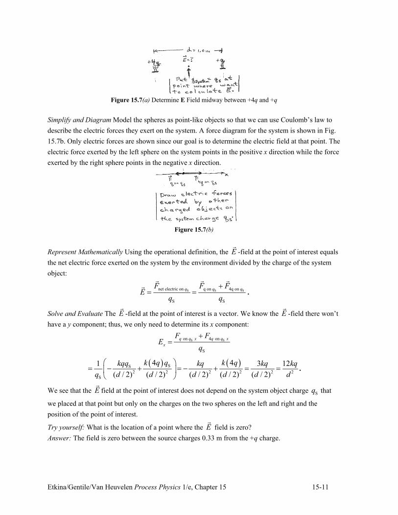
Figure 15.7(a) Determine E Field midway between +4q and +q
Simplify and Diagram Model the spheres as point-like objects so that we can use Coulomb’s law to
describe the electric forces they exert on the system. A force diagram for the system is shown in Fig.
15.7b. Only electric forces are shown since our goal is to determine the electric field at that point. The
electric force exerted by the left sphere on the system points in the positive x direction while the force
exerted by the right sphere points in the negative x direction.
Figure 15.7(b)
Represent Mathematically Using the operational definition, the E!
-field at the point of interest equals
the net electric force exerted on the system by the environment divided by the charge of the system
object:
S S Snet electric on q on 4q on
S S
q q qF F FE
q q
." "
! ! !!
.
Solve and Evaluate The E!
-field at the point of interest is a vector. We know the E!
-field there won’t
have a y component; thus, we only need to determine its x component:
S Son 4 on
S
q q x q q x
x
F FE
q
."
) * ) *SS
2 2 2 2 2 2
S
4 41 3 12
( / 2) ( / 2) ( / 2) ( / 2) ( / 2)
k q q k qkqq kq kq kq
q d d d d d d
# $" + . " + . " "% &
' (.
We see that the E!
field at the point of interest does not depend on the system object charge Sq that
we placed at that point but only on the charges on the two spheres on the left and right and the
position of the point of interest.
Try yourself: What is the location of a point where the E!
field is zero?
Answer: The field is zero between the source charges 0.33 m from the +q charge.
Etkina/Gentile/Van Heuvelen Process Physics 1/e, Chapter 15 15-12
Tip! When we use the operational definition of the E!
-field, our system of interest is an imaginary
point-like charged object located at the point of interest. This charged object is not real. It is part of
the reasoning process used to apply the operational definition for determining the E!
-field.
Note that in the above example, we had the expression
) *
2 2
4
( / 2) ( / 2)x
k qkqE
d d" + . .
The first term on the right side is the x component of the contribution to the E!
-field of the object
with charge q, while the second term on the right could be interpreted is the x component of the
contribution of the object with charge 4q. In other words:
q 4q x x xE E E" . .
Apparently, when multiple charges are contributing to the E!
-field, the way to combine their
contributions is to simply add them as vectors. This is known as the superposition principle.
Superposition principle The E!
-field at a point of interest is the vector sum of the
individual contributions to the E!
-field of each charged object:
1 2 3E E E E" . . .! ! ! !
" (15.5)
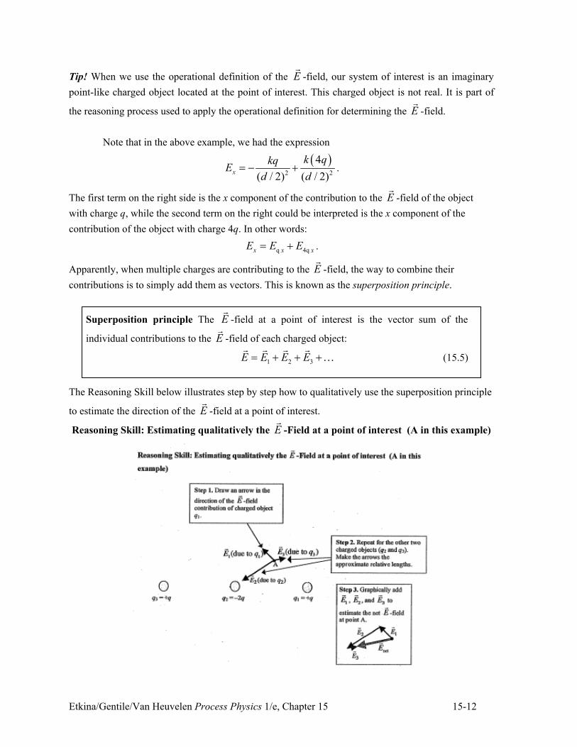
The Reasoning Skill below illustrates step by step how to qualitatively use the superposition principle
to estimate the direction of the E!
-field at a point of interest.
Reasoning Skill: Estimating qualitatively the E!
-Field at a point of interest (A in this example)
Etkina/Gentile/Van Heuvelen Process Physics 1/e, Chapter 15 15-13
E!
-Field Lines
In the Reasoning Skill above the E!
-field at a single point of interest in the vicinity of three
point-like charged objects was estimated. That procedure could be carried out at a hundred other
points, or a thousand, and you still wouldn’t have determined the E!
-field everywhere. There are an
infinite number of points to choose from, and at each point the E!
-field vector is usually different.
That would not be a useful way of representing the overall shape of the E!
-field. Instead, physicists
use E!
-field lines.
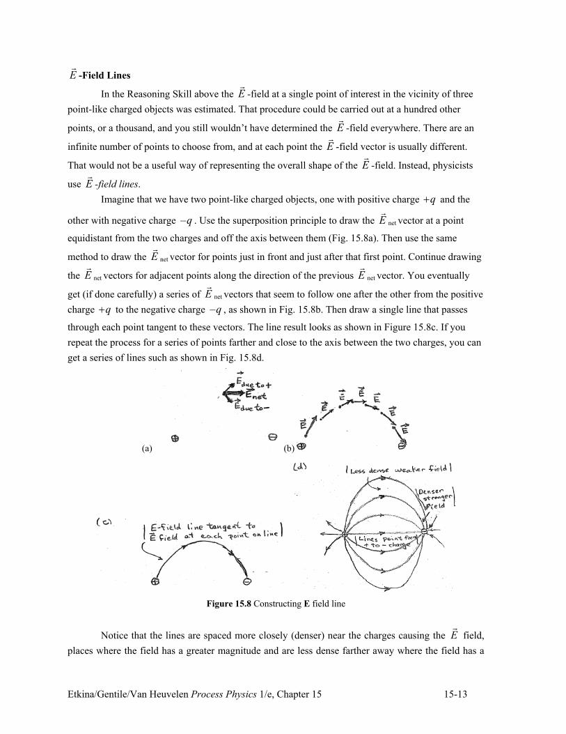
Imagine that we have two point-like charged objects, one with positive charge q. and the
other with negative charge –q . Use the superposition principle to draw the E!
net vector at a point
equidistant from the two charges and off the axis between them (Fig. 15.8a). Then use the same
method to draw the E!
net vector for points just in front and just after that first point. Continue drawing
the E!
net vectors for adjacent points along the direction of the previous E!
net vector. You eventually
get (if done carefully) a series of E!
net vectors that seem to follow one after the other from the positive
charge q. to the negative charge –q , as shown in Fig. 15.8b. Then draw a single line that passes
through each point tangent to these vectors. The line result looks as shown in Figure 15.8c. If you
repeat the process for a series of points farther and close to the axis between the two charges, you can
get a series of lines such as shown in Fig. 15.8d.
(a) (b)
Figure 15.8 Constructing E field line
Notice that the lines are spaced more closely (denser) near the charges causing the E!
field,
places where the field has a greater magnitude and are less dense farther away where the field has a
Etkina/Gentile/Van Heuvelen Process Physics 1/e, Chapter 15 15-14
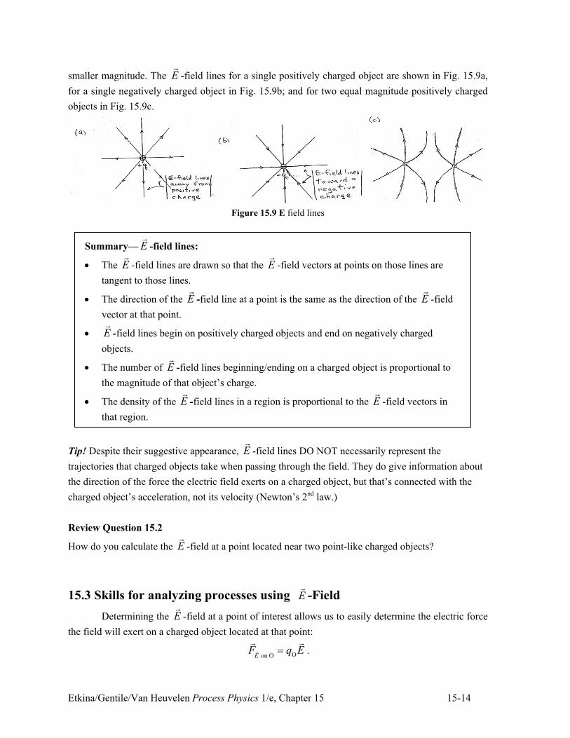
smaller magnitude. The E!
-field lines for a single positively charged object are shown in Fig. 15.9a,
for a single negatively charged object in Fig. 15.9b; and for two equal magnitude positively charged
objects in Fig. 15.9c.
Figure 15.9 E field lines
Summary— E!
-field lines:
! The E!
-field lines are drawn so that the E!
-field vectors at points on those lines are
tangent to those lines.
! The direction of the E!
-field line at a point is the same as the direction of the E!
-field
vector at that point.
! E!
-field lines begin on positively charged objects and end on negatively charged
objects.
! The number of E!
-field lines beginning/ending on a charged object is proportional to
the magnitude of that object’s charge.
! The density of the E!
-field lines in a region is proportional to the E!
-field vectors in
that region.
Tip! Despite their suggestive appearance, E!
-field lines DO NOT necessarily represent the
trajectories that charged objects take when passing through the field. They do give information about
the direction of the force the electric field exerts on a charged object, but that’s connected with the
charged object’s acceleration, not its velocity (Newton’s 2nd law.)
Review Question 15.2
How do you calculate the E!
-field at a point located near two point-like charged objects?
15.3 Skills for analyzing processes using E!
-Field
Determining the E!
-field at a point of interest allows us to easily determine the electric force
the field will exert on a charged object located at that point:
O on OEF q E"!
! !.
Etkina/Gentile/Van Heuvelen Process Physics 1/e, Chapter 15 15-15
Then, we can use Newton’s 2nd law to determine its acceleration, which then lets us determine the
object’s motion. In this section we develop the skills needed to do this.
Determining the E!
-field produced by multiple point-like charged objects
The following Reasoning Skill describes the procedure for determining quantitatively the E!
-field at a
point.
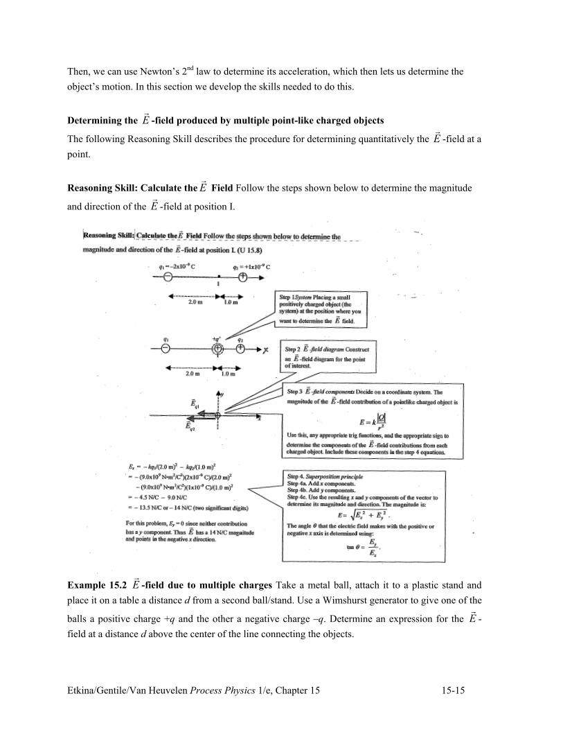
Reasoning Skill: Calculate the E!
Field Follow the steps shown below to determine the magnitude
and direction of the E!
-field at position I.
Example 15.2 E!
-field due to multiple charges Take a metal ball, attach it to a plastic stand and
place it on a table a distance d from a second ball/stand. Use a Wimshurst generator to give one of the
balls a positive charge +q and the other a negative charge –q. Determine an expression for the E!
-
field at a distance d above the center of the line connecting the objects.
Etkina/Gentile/Van Heuvelen Process Physics 1/e, Chapter 15 15-16
Sketch and Translate The sketch in Fig. 15.10a shows the charged objects +q and –q that are
producing the E!
-field, and shows the location of interest (the point where we want to determine the
E!
-field.) Since two charges are contributing to the field, we need to use the superposition principle.
To do this we place an imaginary positively charged object Sq at that location of interest. It is the
system object.
Figure 5.10(a) Determine E field
Simplify and Diagram Next, construct an E!
-field diagram for this point of interest. Draw an E!
-field
arrow for each charged object that contributes to the E!
-field at that point (Fig. 15.10b.) Make the
relative size of the arrows consistent with each other.
Figure 15.10(b)
Represent Mathematically Use Eq. (15.4) to determine the magnitude of the E!
-field contribution
from both +q and –q:
2q q
qE E k
r. +" "
To determine the distance r from +q and –q to the location of interest, use the Pythagorean theorem:
22 2 2
2 2
5( )2 4
5
2
4
55
2
q q
d dr d
dr
q kqE E k
dd. +
" . "
/ "
" " "# $% &' (

Etkina/Gentile/Van Heuvelen Process Physics 1/e, Chapter 15 15-17
Next, the angle 0 that the E!
-field vector makes with the positive x-axis is:
tany
x
E
E0 "
Now determine the x and y components of the E!
-field. Look carefully at Fig. 15.10a and carefully
pay attention to how cos0 is determined. First the x component:
2 2
4 2 8cos cos 2 cos 2
5 5 2 5 5x q x q x q q q
kq d kqE E E E E E
d d d0 0 0. + . + .
# $# $" . " . " " "% &% &' (' (
.
And now the y component:
y y sin sin 0y q q q qE E E E E0 0. + . +" . " . + "
Notice that the y components of the two E!
-field contributions cancel. This happened because of what
is known as the symmetry of the situation. The magnitudes of +q and –q are the same, and the
distances from them to the point of interest are the same. Thus, their y components have equal
magnitudes, but one pointing in the +y direction and the other in the -y direction; so that they add to
zero.
We can now determine the direction of the E!
-field. Since its y component is zero, it must
point in the positive x direction. Let’s check:
) *
2
1
0tan 0
8
5 5
tan 0 0
y
x
E
kqE
d
0
0 +
" " "
/ " " 1
Solve and Evaluate The magnitude of the E!
-field is
2
2 2 2
2 2
8 80
5 5 5 5x y
kq kqE E E
d d
# $" . " . "% &
' (
and it points at an angle of ) *1tan 0 00 +" " 1 counterclockwise from the positive x direction,
meaning that it points exactly in the positive x direction. The units are appropriate (using the above
equation for E):
2
2
2
N mC
C N
m C
# $-% &' ( "
Try It Yourself: Determine the E!
-field at point I in Fig. 15.11. (a) Calculate the magnitudes of the
E!
-field contributions from each of the charged objects at point I. (b) Calculate the x and y
components of those E!
-field contributions. (c) Determine the net x and y components of the E!
-field
at point I. (d) Finally, determine the magnitude and the direction of the E!
-field at point I.
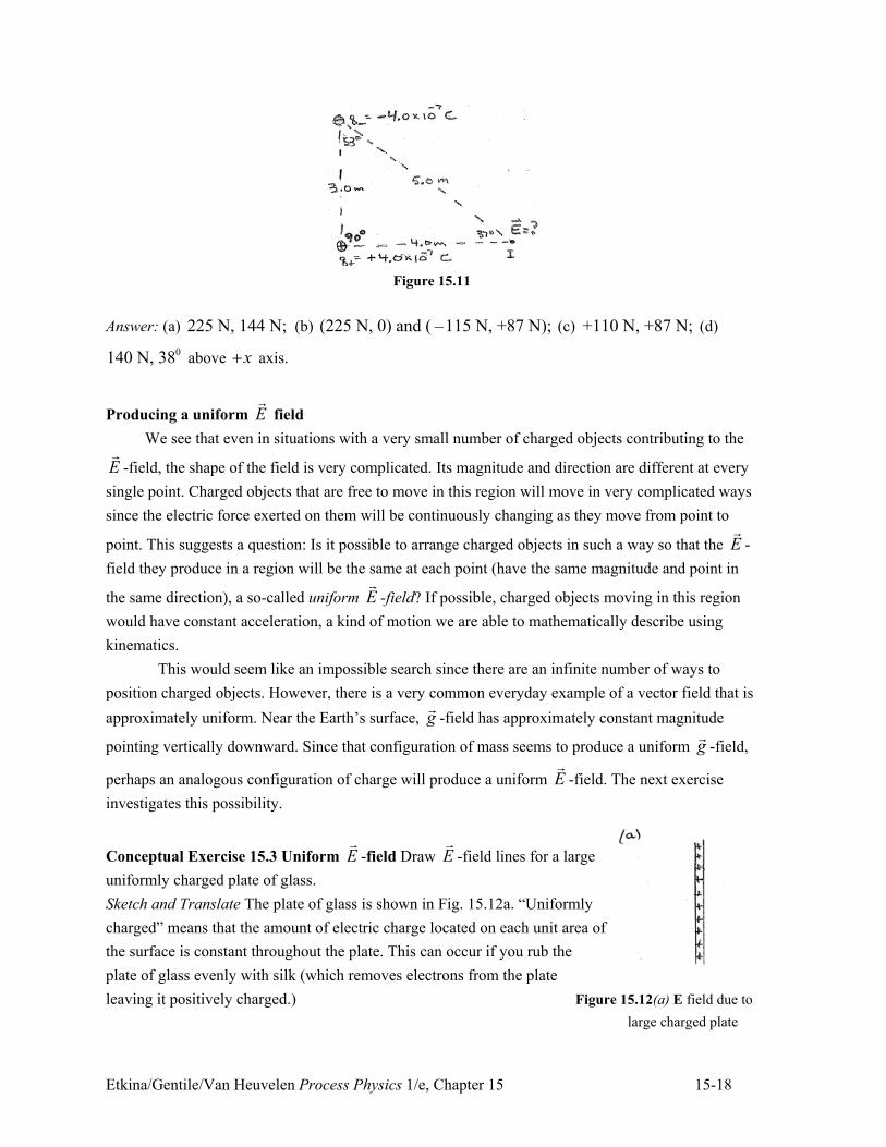
Etkina/Gentile/Van Heuvelen Process Physics 1/e, Chapter 15 15-18
Figure 15.11
Answer: (a) 225 N, 144 N; (b) (225 N, 0) and ( –115 N, +87 N); (c) +110 N, +87 N; (d)
0140 N, 38 above x. axis.
Producing a uniform E!
field
We see that even in situations with a very small number of charged objects contributing to the
E!
-field, the shape of the field is very complicated. Its magnitude and direction are different at every
single point. Charged objects that are free to move in this region will move in very complicated ways
since the electric force exerted on them will be continuously changing as they move from point to
point. This suggests a question: Is it possible to arrange charged objects in such a way so that the E!
-
field they produce in a region will be the same at each point (have the same magnitude and point in
the same direction), a so-called uniform E!
-field? If possible, charged objects moving in this region
would have constant acceleration, a kind of motion we are able to mathematically describe using
kinematics.
This would seem like an impossible search since there are an infinite number of ways to
position charged objects. However, there is a very common everyday example of a vector field that is
approximately uniform. Near the Earth’s surface, g!
-field has approximately constant magnitude
pointing vertically downward. Since that configuration of mass seems to produce a uniform g!
-field,
perhaps an analogous configuration of charge will produce a uniform E!
-field. The next exercise
investigates this possibility.
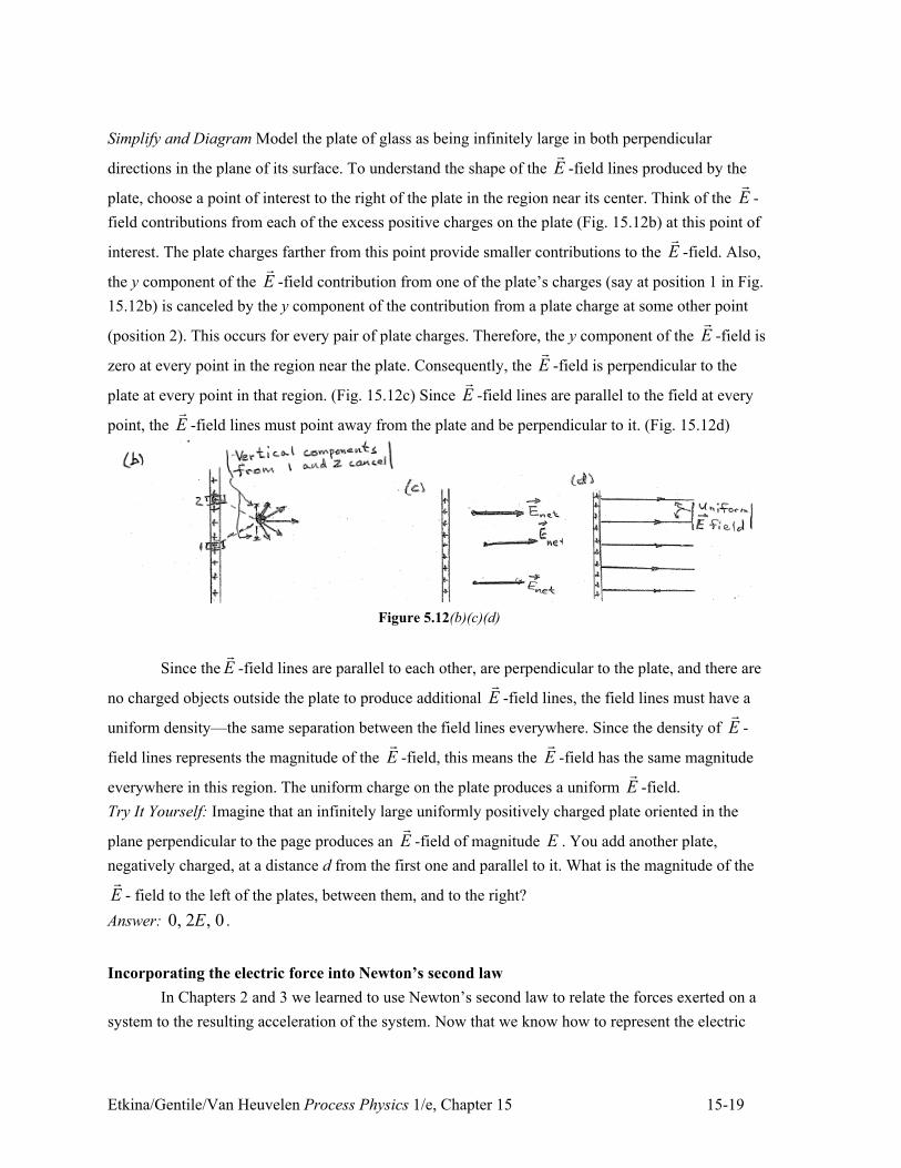
Conceptual Exercise 15.3 Uniform E!
-field Draw E!
-field lines for a large
uniformly charged plate of glass.
Sketch and Translate The plate of glass is shown in Fig. 15.12a. “Uniformly
charged” means that the amount of electric charge located on each unit area of
the surface is constant throughout the plate. This can occur if you rub the
plate of glass evenly with silk (which removes electrons from the plate
leaving it positively charged.) Figure 15.12(a) E field due to
large charged plate
Etkina/Gentile/Van Heuvelen Process Physics 1/e, Chapter 15 15-19
Simplify and Diagram Model the plate of glass as being infinitely large in both perpendicular
directions in the plane of its surface. To understand the shape of the E!
-field lines produced by the
plate, choose a point of interest to the right of the plate in the region near its center. Think of the E!
-
field contributions from each of the excess positive charges on the plate (Fig. 15.12b) at this point of
interest. The plate charges farther from this point provide smaller contributions to the E!
-field. Also,
the y component of the E!
-field contribution from one of the plate’s charges (say at position 1 in Fig.
15.12b) is canceled by the y component of the contribution from a plate charge at some other point
(position 2). This occurs for every pair of plate charges. Therefore, the y component of the E!
-field is
zero at every point in the region near the plate. Consequently, the E!
-field is perpendicular to the
plate at every point in that region. (Fig. 15.12c) Since E!
-field lines are parallel to the field at every
point, the E!
-field lines must point away from the plate and be perpendicular to it. (Fig. 15.12d)
Figure 5.12(b)(c)(d)
Since the E!
-field lines are parallel to each other, are perpendicular to the plate, and there are
no charged objects outside the plate to produce additional E!
-field lines, the field lines must have a
uniform density—the same separation between the field lines everywhere. Since the density of E!
-
field lines represents the magnitude of the E!
-field, this means the E!
-field has the same magnitude
everywhere in this region. The uniform charge on the plate produces a uniform E!
-field.
Try It Yourself: Imagine that an infinitely large uniformly positively charged plate oriented in the
plane perpendicular to the page produces an E!
-field of magnitude E . You add another plate,
negatively charged, at a distance d from the first one and parallel to it. What is the magnitude of the
E!
- field to the left of the plates, between them, and to the right?
Answer: 0, 2 , 0E .
Incorporating the electric force into Newton’s second law
In Chapters 2 and 3 we learned to use Newton’s second law to relate the forces exerted on a
system to the resulting acceleration of the system. Now that we know how to represent the electric
Etkina/Gentile/Van Heuvelen Process Physics 1/e, Chapter 15 15-20
interaction as a force ( E.f. on O OF q E"! !
), we can use Newton’s second law to determine the motion of
charged objects that have electric forces exerted on them. A general problem solving strategy for
doing this is described and illustrated in Example 15.4.
Example 15.4 A charged object in a known E!
-field A spring made of a dielectric (electrically
insulating) material with spring constant 50 N/m hangs from a large uniformly charged horizontal
plate. The uniform E!
-field produced by the plate has magnitude 52.0 10 N C, and points down. A
0.20-kg ball with charge 54.0 10 C+. , hangs at the end of the spring. Determine the distance the
spring is stretched from its equilibrium length. Assume that the gravitational constant is 10 N/kg .
Sketch and Translate
• Draw a labeled sketch of the situation. Include the
symbols for the known and unknown quantities that you
plan to use.
• Choose a system of interest.
The situation is sketched at the right. The charged ball is
the system of interest.
Simplify and Diagram
• Determine the E!
-field produced by the environment.
Is it produced by pointlike charges (making it non-
uniform) or by large charged plates (making it
uniform)?
• Construct a force diagram for the system.
• State any assumptions you have made.
The field is uniform.
Assume that the spring
has no mass. A force
diagram for the system is
shown at the right with
arrows drawn to scale.
Represent Mathematically
! Use the force diagram to help apply Newton’s second
law in component form. Use component addition to
determine the net force along each coordinate axis.
Determine the acceleration of the system if needed.
! If necessary, use kinematics equations to describe the
motion of the system.
The ball is not accelerating so the forces exerted on the
ball balance. None of the forces have x components:
S on B E on B Plate on B
( ) ( ) 0
0y y y
k x mg qE
mg qEx
k
F F F
/ 2 . + . + "
./ 2 "
. . "
Solve and Evaluate
! Combine the above equations and complete the
solution.
! Check the direction, magnitude, and units, and decide
whether the result makes sense in limiting cases.
5 5(0.20 kg)(10 N/kg) (4.0 10 C)(2.0 10 N/C)
50 N/mx
+. , ,2 "
0.20 mx/ 2 "
The units for the stretch distance are meters, as they
should be. Let us check it for the limiting cases. As both
the gravitational force and the electric force point in the
same direction, eliminating either of them should reduce
the distance that the spring stretches. Note in the
Etkina/Gentile/Van Heuvelen Process Physics 1/e, Chapter 15 15-21
equation above that x2 decreases if 0m " or if 0q " .
Also, a stiff spring (larger k ) should stretch less if we
have the same mass ball and the same electric charge –
also consistent with our result.
Try It Yourself: Suppose the plate was negatively charged producing the same magnitude electric
field but now pointing up. Now, what would the spring stretch or compression be?
Answer: –0.12 m (the spring is compressed 0.12 m).
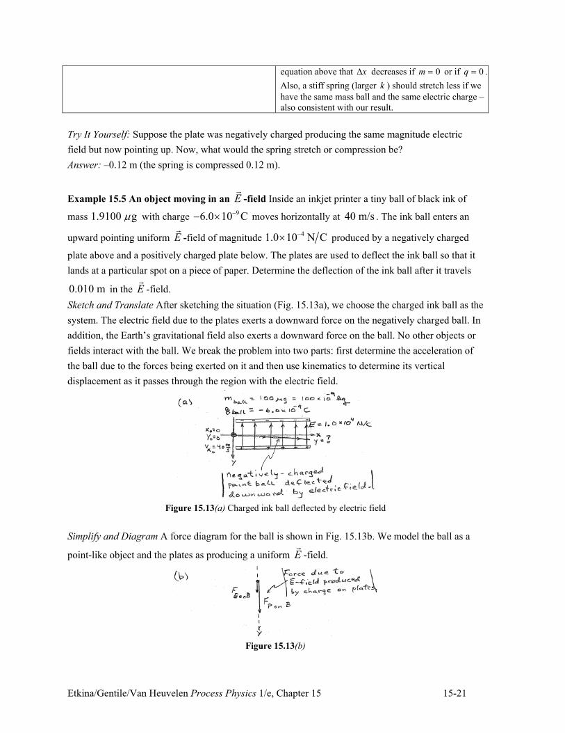
Example 15.5 An object moving in an E!
-field Inside an inkjet printer a tiny ball of black ink of
mass 1.9100 g3 with charge 96.0 10 C++ , moves horizontally at 40 m/s . The ink ball enters an
upward pointing uniform E!
-field of magnitude 41.0 10 N C+, produced by a negatively charged
plate above and a positively charged plate below. The plates are used to deflect the ink ball so that it
lands at a particular spot on a piece of paper. Determine the deflection of the ink ball after it travels
0.010 m in the E!
-field.
Sketch and Translate After sketching the situation (Fig. 15.13a), we choose the charged ink ball as the
system. The electric field due to the plates exerts a downward force on the negatively charged ball. In
addition, the Earth’s gravitational field also exerts a downward force on the ball. No other objects or
fields interact with the ball. We break the problem into two parts: first determine the acceleration of
the ball due to the forces being exerted on it and then use kinematics to determine its vertical
displacement as it passes through the region with the electric field.
Figure 15.13(a) Charged ink ball deflected by electric field
Simplify and Diagram A force diagram for the ball is shown in Fig. 15.13b. We model the ball as a
point-like object and the plates as producing a uniform E!
-field.
Figure 15.13(b)
Etkina/Gentile/Van Heuvelen Process Physics 1/e, Chapter 15 15-22
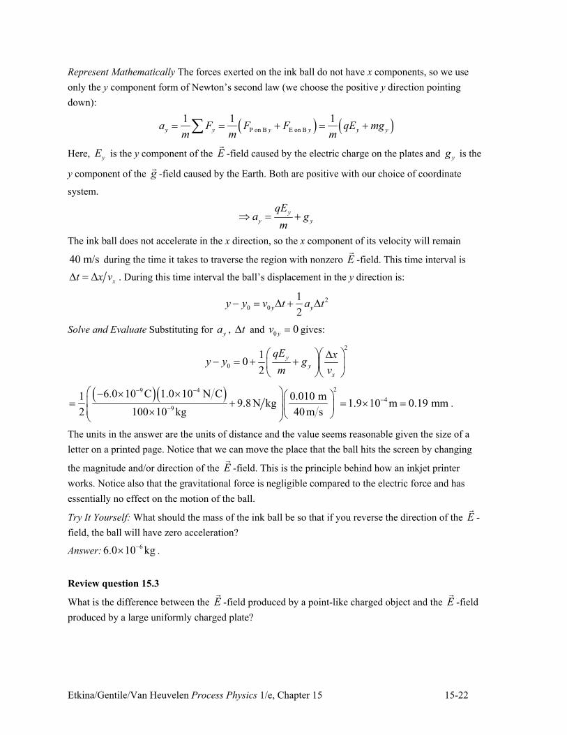
Represent Mathematically The forces exerted on the ink ball do not have x components, so we use
only the y component form of Newton’s second law (we choose the positive y direction pointing
down):
) * ) *P on B E on B
1 1 1y y y y y ya F F F qE mg
m m m" " . " .4
Here, yE is the y component of the E!
-field caused by the electric charge on the plates and yg is the
y component of the g!
-field caused by the Earth. Both are positive with our choice of coordinate
system.
y
y y
qEa g
m/ " .
The ink ball does not accelerate in the x direction, so the x component of its velocity will remain
40 m/s during the time it takes to traverse the region with nonzero E!
-field. This time interval is
xt x v2 " 2 . During this time interval the ball’s displacement in the y direction is:
2
0 0
1
2y yy y v t a t+ " 2 . 2
Solve and Evaluate Substituting for ya , t2 and 0 0yv " gives:
2
0
10
2
y
y
x
qE xy y g
m v
# $# $ 2+ " . . % &% &
' (' (
) *) * 29 4
4
9
6.0 10 C 1.0 10 N C1 0.010 m9.8 N kg 1.9 10 m 0.19 mm
2 100 10 kg 40m s
+ +
++
# $+ , , # $% &" . " , "% &% &, ' (' (
.
The units in the answer are the units of distance and the value seems reasonable given the size of a
letter on a printed page. Notice that we can move the place that the ball hits the screen by changing
the magnitude and/or direction of the E!
-field. This is the principle behind how an inkjet printer
works. Notice also that the gravitational force is negligible compared to the electric force and has
essentially no effect on the motion of the ball.
Try It Yourself: What should the mass of the ink ball be so that if you reverse the direction of the E!
-
field, the ball will have zero acceleration?
Answer:66.0 10 kg+, .
Review question 15.3
What is the difference between the E!
-field produced by a point-like charged object and the E!
-field
produced by a large uniformly charged plate?
Etkina/Gentile/Van Heuvelen Process Physics 1/e, Chapter 15 15-23
15.4 The V-field
We operationally defined the E!
-field at a specific location as the net electric force exerted by
the environment on a positively charged point-like object located there, divided by that object’s
charge:
Environment on Object
Object
FE
q"
!!
.
The magnitude of the E!
-field produced a distance r from a charge Q is
2
kQE
r" .
The E!
-field vectors of a single positively charged object at any location point away from it and
toward a negatively charged object. The E!
-field produced at any point by multiple environmental
objects is the vector sum of the E!
-fields produced by each environmental charged object. If a system
object with charge Oq happens to be in that E!
-field, the field exerts an electric force on the object:
E.f. on O OF q E"! !
.
This allows us to incorporate electric forces into Newton’s second law, which then allows us to
predict the motion of charged objects affected by the electric field.
However, while studying mechanical phenomena, we found that using a work-energy
approach was often an easier way to analyze certain processes. Now our goal is to incorporate the
electric interaction into that work-energy approach. In order to do this we need to describe the electric
field not as the force-related E!
-field, but instead as an energy-related field.
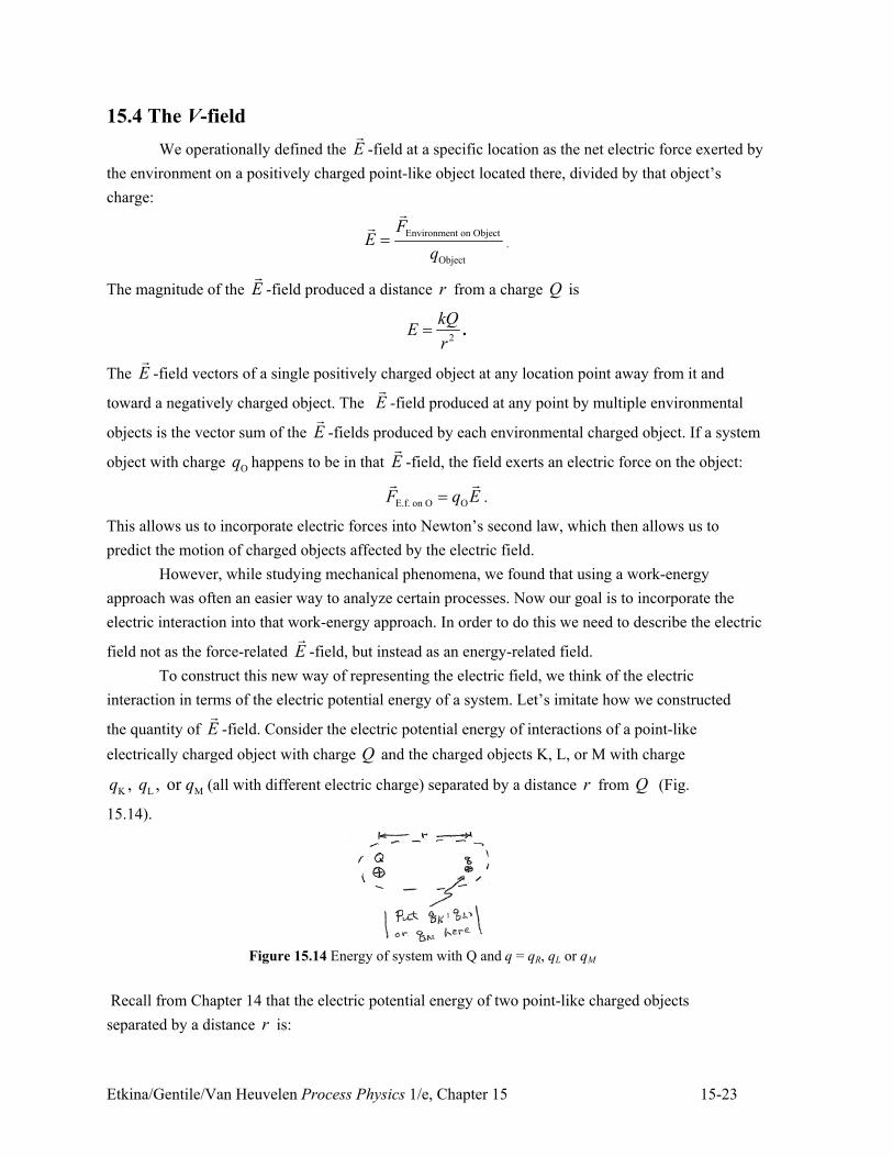
To construct this new way of representing the electric field, we think of the electric
interaction in terms of the electric potential energy of a system. Let’s imitate how we constructed
the quantity of E!
-field. Consider the electric potential energy of interactions of a point-like
electrically charged object with charge Q and the charged objects K, L, or M with charge
K L M, , or q q q (all with different electric charge) separated by a distance r from Q (Fig.
15.14).
Figure 15.14 Energy of system with Q and q = qR, qL or qM
Recall from Chapter 14 that the electric potential energy of two point-like charged objects
separated by a distance r is:
Etkina/Gentile/Van Heuvelen Process Physics 1/e, Chapter 15 15-24
1 2
1 2q q
kq qU
r" .
Thus, the electric potential energy of charges K L M and , , or Q q q q is:
K
Kq Q K
kq Q kQU q
r r
# $" " % &' (
L
LLq Q
kq Q kQU q
r r
# $" " % &' (
M
MMq Q
kq Q kQU q
r r
# $" " % &' (
If we consider ratios between the electric potential energy of the Q - K L M, , or q q q charge pair
and the charges K L M, , or q q q (that is /qQU q ), we find that all three ratios equal the same
quantity:
K L M
K L M
q Q q Q q QU U U kQ
q q q r" " " .
Since these ratios all have the same value ( kQ r ), it suggests that this ratio could be a mathematical
representation of the electric energy field caused by charge Q at a distance r from Q . We call this
physical quantity the V field or electric potential due to Q .
V-field (or electric potential) The V-field is a physical quantity that characterizes the energy
(as opposed to the force) of the electric field at a specific position. It equals the total electric
potential energy QqU of the system consisting of an imaginary positively charged point-like
object q located at that position and the objects creating the field divided by the charge of
the object with charge q :
all QqU
Vq
" (15.6)
The unit of the V-field is called the volt (V) where 1 V = 1 J/C (joule/coulomb).
The V-field is another way of representing the electric disturbance that charged objects
produce in the regions surrounding themselves; but in this case, it’s connected with ideas of
work-energy instead of forces. Using this operational definition of the V-field, we can say that the
electric potential energy qU of a system of a point-like charge Oq and all charged objects
creating the V-field at Oq ’s location is:
OqU q V" (15.7)
Etkina/Gentile/Van Heuvelen Process Physics 1/e, Chapter 15 15-25
Tip! Unlike the E!
field, which is a vector, the physical quantity V-field (electric potential) is a scalar.
Thus, it can have a positive or a negative value depending on the signs of the electric charges of the
objects that create the V-field at a particular location.
Electric potential due to single negatively-charged object
Let’s use what we have been learning to analyze the V-field of a single negatively-charged
point-like object at different distances from the object.
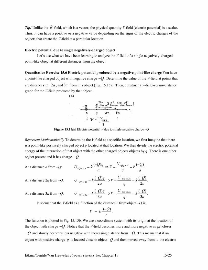
Quantitative Exercise 15.6 Electric potential produced by a negative point-like charge You have
a point-like charged object with negative charge Q+ . Determine the value of the V-field at points that
are distances a , 2a , and3a from this object (Fig. 15.15a). Then, construct a V-field-versus-distance
graph for the V-field produced by that object.
Figure 15.15(a) Electric potential V due to single negative charge –Q
Represent Mathematically To determine the V-field at a specific location, we first imagine that there
is a point-like positively charged object q located at that location. We then divide the electric potential
energy of the interaction of that object with the other charged objects objects by q. There is one other
object present and it has charge Q+ .
At a distance a from –Q: – at a
– at a
UQ q QU k V k
a q a" / " " .
At a distance 2a from –Q: – at 2a
– at 2a
(– ) (– )
2 2
UQ q QU k V k
a q a" / " " .
At a distance 3a from –Q: – at 3a
– at 3a
(– ) (– )
3 3
UQ q QU k V k
a q a" / " " .
It seems that the V-field as a function of the distance r from object –Q is:
(– )
QV k
r" .
The function is plotted in Fig. 15.15b. We use a coordinate system with its origin at the location of
the object with charge Q+ . Notice that the V-field becomes more and more negative as get closer
Q+ and slowly becomes less negative with increasing distance from Q+ . This means that if an
object with positive charge q is located close to object –Q and then moved away from it, the electric
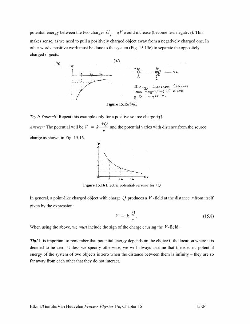
Etkina/Gentile/Van Heuvelen Process Physics 1/e, Chapter 15 15-26
potential energy between the two charges qU qV" would increase (become less negative). This
makes sense, as we need to pull a positively charged object away from a negatively charged one. In
other words, positive work must be done to the system (Fig. 15.15c) to separate the oppositely
charged objects.
Figure 15.15(b)(c)
Try It Yourself: Repeat this example only for a positive source charge +Q.
Answer: The potential will be +
Q
V kr
" and the potential varies with distance from the source
charge as shown in Fig. 15.16.
Figure 15.16 Electric potential-versus-r for +Q
In general, a point-like charged object with charge Q produces a V -field at the distance r from itself
given by the expression:
Q
V kr
" . (15.8)
When using the above, we must include the sign of the charge causing the -fieldV .
Tip! It is important to remember that potential energy depends on the choice if the location where it is
decided to be zero. Unless we specify otherwise, we will always assume that the electric potential
energy of the system of two objects is zero when the distance between them is infinity – they are so
far away from each other that they do not interact.
Etkina/Gentile/Van Heuvelen Process Physics 1/e, Chapter 15 15-27
Comparing the E!
field and the potential field V
Compare the equation for the magnitude of the E!
-field due to a point-like charged object
with charge Q at a distance r from the object
2
QE k
r"
and the -fieldV due to that same charged object at that same distance r from the object:
Q
V kr
" .
They are similar in that they both depend on the charge of the object and on the distance from that
object to the location of interest. However, there are differences. First, since E is the magnitude of the
vector E!
-field, it is always positive regardless of the sign of the object’s charge (the absolute value
in the equation guarantees this). On the other hand, V can be either positive or negative depending on
the sign of the charge. Secondly, E is proportional to 21 r whereas V is proportional to 1 r . This
means that E decreases with distance from the object more quickly than V does.
The V-field and the superposition principle
Now that we can determine mathematically the V-field produced by a single point-like
charged object (Eq. 15.8), we can use the superposition principle to determine the V-field at a specific
location produced by several charged objects. Using the same idea as for the E!
-field we have:
1 2 3V V V V" . . ." (15.9)
Because the V-field is a scalar field rather than a vector field (like E!
-field is), it is much easier to
apply the superposition principle. Just as in mechanics, the energy approach (representing the electric
field with the V-field) is often easier than the force approach (representing the electric field with the
E!
-field.)
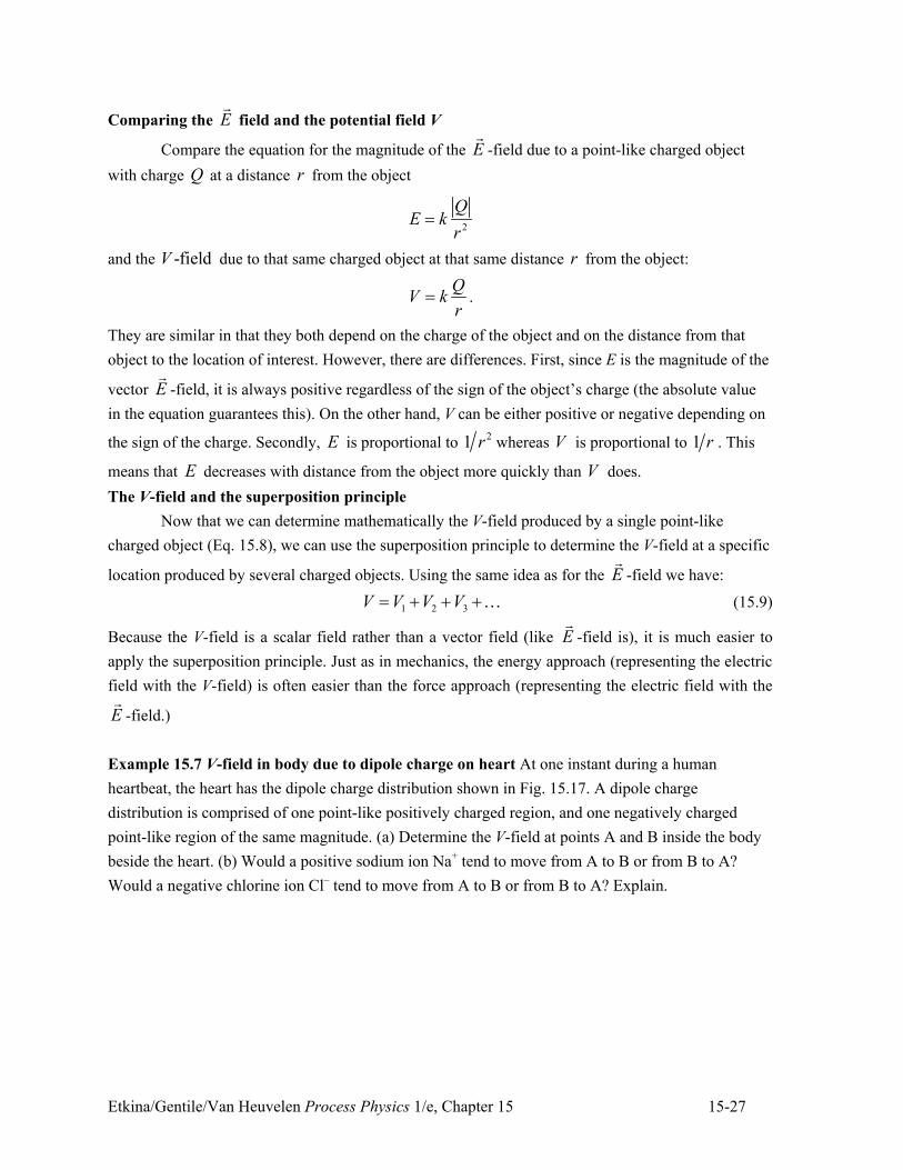
Example 15.7 V-field in body due to dipole charge on heart At one instant during a human
heartbeat, the heart has the dipole charge distribution shown in Fig. 15.17. A dipole charge
distribution is comprised of one point-like positively charged region, and one negatively charged
point-like region of the same magnitude. (a) Determine the V-field at points A and B inside the body
beside the heart. (b) Would a positive sodium ion Na+ tend to move from A to B or from B to A?
Would a negative chlorine ion Cl– tend to move from A to B or from B to A? Explain.
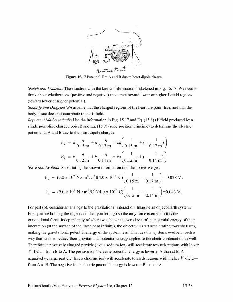
Etkina/Gentile/Van Heuvelen Process Physics 1/e, Chapter 15 15-28
Figure 15.17 Potential V at A and B due to heart dipole charge
Sketch and Translate The situation with the known information is sketched in Fig. 15.17. We need to
think about whether ions (positive and negative) accelerate toward lower or higher V-field regions
(toward lower or higher potential).
Simplify and Diagram We assume that the charged regions of the heart are point-like, and that the
body tissue does not contribute to the V-field.
Represent Mathematically Use the information in Fig. 15.17 and Eq. (15.8) (V-field produced by a
single point-like charged object) and Eq. (15.9) (superposition principle) to determine the electric
potential at A and B due to the heart dipole charges
A
– 1 1 + = + (– )
0.15 m 0.17 m 0.15 m 0.17 m
q qV k k kq
# $" % &' (
B
– 1 1 + = + (– )
0.12 m 0.14 m 0.12 m 0.14 m
q qV k k kq
# $" % &' (
Solve and Evaluate Substituting the known information into the above, we get:
9 2 2 –7
A
1 1 (9.0 x 10 N m /C )(4.0 x 10 C) – = 0.028 V
0.15 m 0.17 mV
# $" , % &' (
.
9 2 2 –7
B
1 1 (9.0 x 10 N m /C )(4.0 x 10 C) – =0.043 V
0.12 m 0.14 mV
# $" , % &' (
.
For part (b), consider an analogy to the gravitational interaction. Imagine an object-Earth system.
First you are holding the object and then you let it go so the only force exerted on it is the
gravitational force. Independently of where we choose the zero level of the potential energy of their
interaction (at the surface of the Earth or at infinity), the object will start accelerating towards Earth,
making the gravitational potential energy of the system less. This idea that systems evolve in such a
way that tends to reduce their gravitational potential energy applies to the electric interaction as well.
Therefore, a positively charged particle (like a sodium ion) will accelerate towards regions with lower
V -field—from B to A. The positive ion’s electric potential energy is lower at A than at B. A
negatively-charge particle (like a chlorine ion) will accelerate towards regions with higher V -field—
from A to B. The negative ion’s electric potential energy is lower at B than at A.
Etkina/Gentile/Van Heuvelen Process Physics 1/e, Chapter 15 15-29
Try It Yourself: Determine qualitatively the direction of the net electric force that the dipole charges
exert (a) on a positive sodium ion half way between A and B and (b) on a negative chlorine ion that is
half way between A and B. Is this consistent with the idea that a charged object tends to move toward
regions of where the electric potential energy of the system is lower ? Explain.
Answer: (a) The net force that the heart’s dipole charges exert on a positive sodium ion is toward A
(the positive ion of the heart dipole is closer to the sodium ion and exerts a stronger repulsive force
than the attractive force exerted by the negative ion on the sodium ion). Note also that the heart
dipole- sodium ion system has less electric potential energy at A. (b) The net force that the dipole
charges exert on a chlorine ion is toward B (the heart’s positive ion is closer to the chlorine ion and
exerts a stronger attractive force than the repulsive force exerted by the heart’s negative dipole
charge). Note also that the heart dipole-chlorine ion system has lower electric potential energy at B.
Electrocardiogram
Our heart contracts in a rhythmical way pumping blood through the body. How does it know
when to contract? The rhythm of the heart is controlled by the nerve cells that produce electrical
impulses called action potentials that trigger the electrical activity of the heart. The electrical action
potentials come from cell membranes where chemical processes cause different concentrations of
positive and negative ions on the two sides of the membranes. This is an example of charge
separation (polarization) and produces a V-field that varies from one side of the membrane to the
other (known as a potential difference.) When some event triggers a depolarization of the membrane,
the potential difference across it changes. Such changes occur in different muscle cells in the heart
and collectively cause different parts of the heart to contract at different times in the heart beat cycle.
The charge separation in the heart is what an electrocardiogram measures. In other words, it
measures the potential difference (the difference in the value of the V -field) produced by the dipole
charges of the heart. The dipole charges depend on which heart muscle cells are compressing at a
particular time. For example, during a person’s left ventricle contraction (the main pump for the
heart), a large number of muscle cells are contracting and the dipole charge distribution is greater than
during left ventricular contraction when blood is pumped from the heart to the lungs. The more
muscle cells contracting, the greater the heart’s electric dipole and the greater the difference in the
V -field between different parts of the body away from the heart. If the heart has to work harder than
usual because of clogged arteries or a congested peripheral circulatory system, then the heart muscles
contract more when pumping the blood and the dipole charge is larger than in a healthy heart. The
larger dipole charge produces a larger potential difference, which is easily measured by an
electrocardiogram. We will return to the details of the electrocardiogram in the last section of this
chapter.
The V-field or electric potential will be a very useful physical quantity in understanding
electric circuits in Chapter 16. It is also useful in analyzing processes where the electric interaction is
used to accelerate charged objects such as in television sets, x-ray machines, and particle accelerators.
Etkina/Gentile/Van Heuvelen Process Physics 1/e, Chapter 15 15-30
Review question 15.4
How do you determine the V-field at a chosen location of interest?
15.5 Equipotential lines—representing the V-field
We’ve used E!
-field lines to help visualize the E!
-field. In this section we will learn a new
graphical representation for the V-field that helps us visualize it. Examine the V-field at different
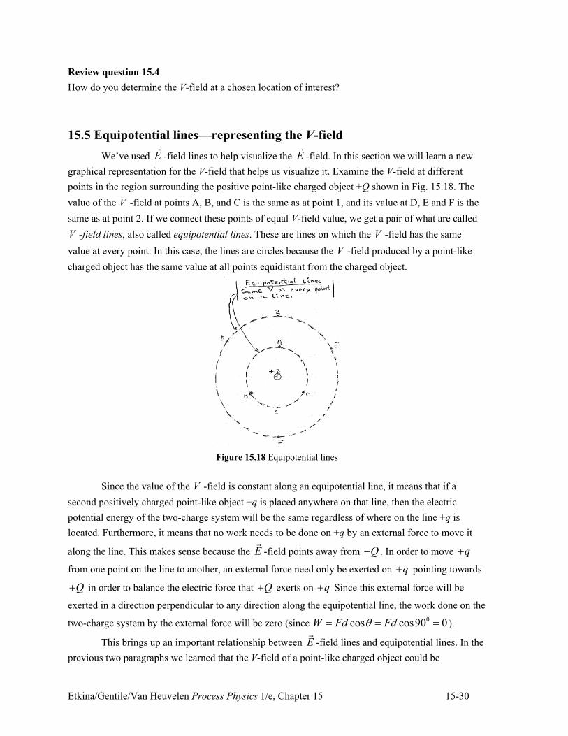
points in the region surrounding the positive point-like charged object +Q shown in Fig. 15.18. The
value of the V -field at points A, B, and C is the same as at point 1, and its value at D, E and F is the
same as at point 2. If we connect these points of equal V-field value, we get a pair of what are called
V -field lines, also called equipotential lines. These are lines on which the V -field has the same
value at every point. In this case, the lines are circles because the V -field produced by a point-like
charged object has the same value at all points equidistant from the charged object.
Figure 15.18 Equipotential lines
Since the value of the V -field is constant along an equipotential line, it means that if a
second positively charged point-like object +q is placed anywhere on that line, then the electric
potential energy of the two-charge system will be the same regardless of where on the line +q is
located. Furthermore, it means that no work needs to be done on +q by an external force to move it
along the line. This makes sense because the E!
-field points away from Q. . In order to move q.
from one point on the line to another, an external force need only be exerted on q. pointing towards
Q. in order to balance the electric force that Q. exerts on q. Since this external force will be
exerted in a direction perpendicular to any direction along the equipotential line, the work done on the
two-charge system by the external force will be zero (since 0cos cos90 0W Fd Fd0" " " ).
This brings up an important relationship between E!
-field lines and equipotential lines. In the
previous two paragraphs we learned that the V-field of a point-like charged object could be
Etkina/Gentile/Van Heuvelen Process Physics 1/e, Chapter 15 15-31
represented by spherical equipotential lines centered on the object. We also remembered that the E!
-
field of that same object can be represented with E!
-field lines that point radially away from the
object. This means that the equipotential lines and the E!
-field lines are everywhere perpendicular. If
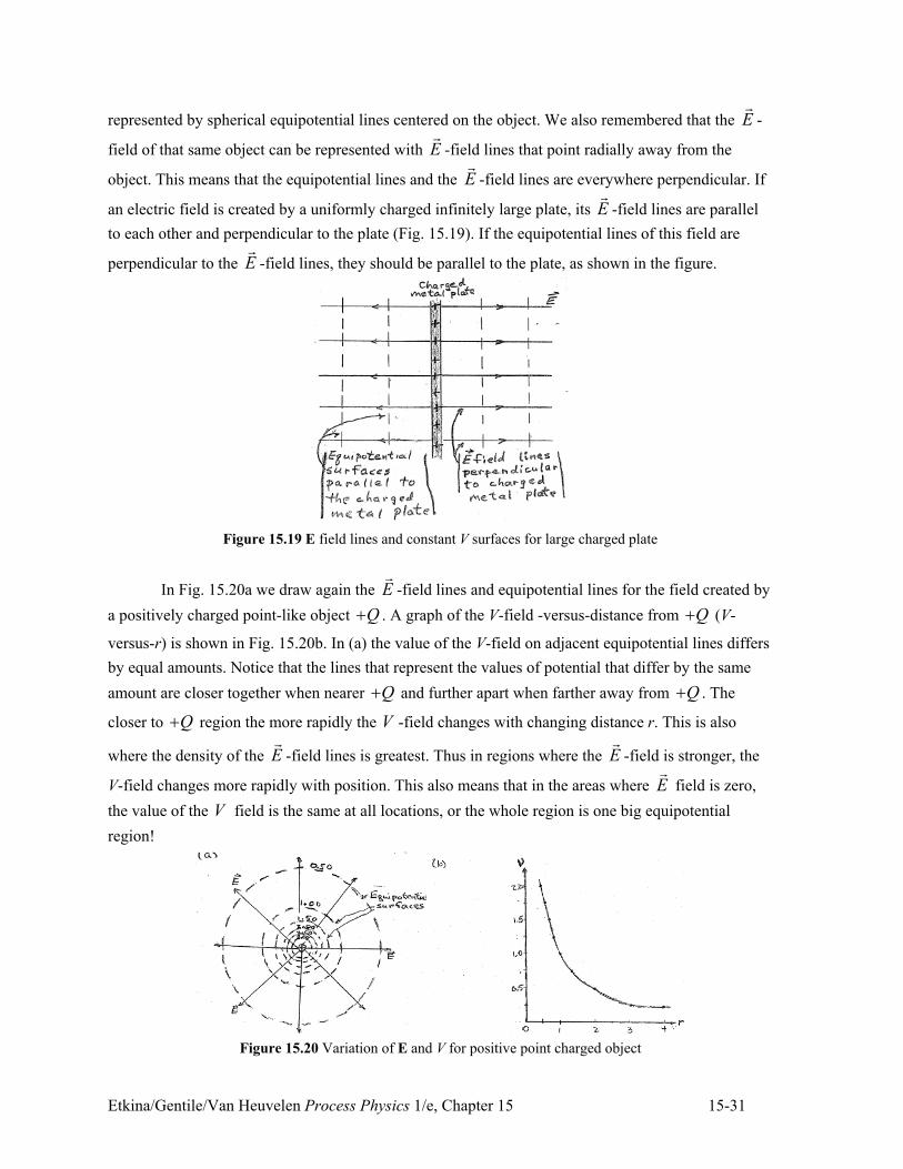
an electric field is created by a uniformly charged infinitely large plate, its E!
-field lines are parallel
to each other and perpendicular to the plate (Fig. 15.19). If the equipotential lines of this field are
perpendicular to the E!
-field lines, they should be parallel to the plate, as shown in the figure.
Figure 15.19 E field lines and constant V surfaces for large charged plate
In Fig. 15.20a we draw again the E!
-field lines and equipotential lines for the field created by
a positively charged point-like object Q. . A graph of the V-field -versus-distance from Q. (V-
versus-r) is shown in Fig. 15.20b. In (a) the value of the V-field on adjacent equipotential lines differs
by equal amounts. Notice that the lines that represent the values of potential that differ by the same
amount are closer together when nearer Q. and further apart when farther away from Q. . The
closer to Q. region the more rapidly the V -field changes with changing distance r. This is also
where the density of the E!
-field lines is greatest. Thus in regions where the E!
-field is stronger, the
V-field changes more rapidly with position. This also means that in the areas where E!
field is zero,
the value of the V field is the same at all locations, or the whole region is one big equipotential
region!
Figure 15.20 Variation of E and V for positive point charged object
Etkina/Gentile/Van Heuvelen Process Physics 1/e, Chapter 15 15-32
Remember that an object interacting with Earth only accelerates in a direction that will
decrease the gravitational potential energy of the object-Earth system. As an example, an object that
is thrown upwards has a downward acceleration, which is the direction of decreasing gravitational
potential energy of the object-Earth system. Charged objects that are interacting electrically follow a
similar pattern, accelerating in a direction that decreases the electric potential energy of the system.
The situation with electrically charged objects is somewhat more complicated since the electric
charge of an object can be either positive or negative while the mass of an object can only be positive.
Let’s investigate this.
Looking at Figs. 15.19 and 15.20 we can see that the E!
-field points perpendicular to the
equipotential lines and toward regions of lower V-field value. This means that a positively charged
object accelerates from regions of higher V -field value toward regions of lower V -field value. A
negatively charged particle tends to do the opposite, accelerating from regions of lower V -field value
toward regions of higher V -field value. In either case, the change in electric potential energy of the
system is
) * f i f i f iq q
q
U U qV qV q V V
U q V
+ " + " +
/ 2 " 2.
This change in electric potential energy can be positive or negative depending on the sign of the
charge q that is moving, and the V -field values ( iV and fV ) at its initial and final locations.
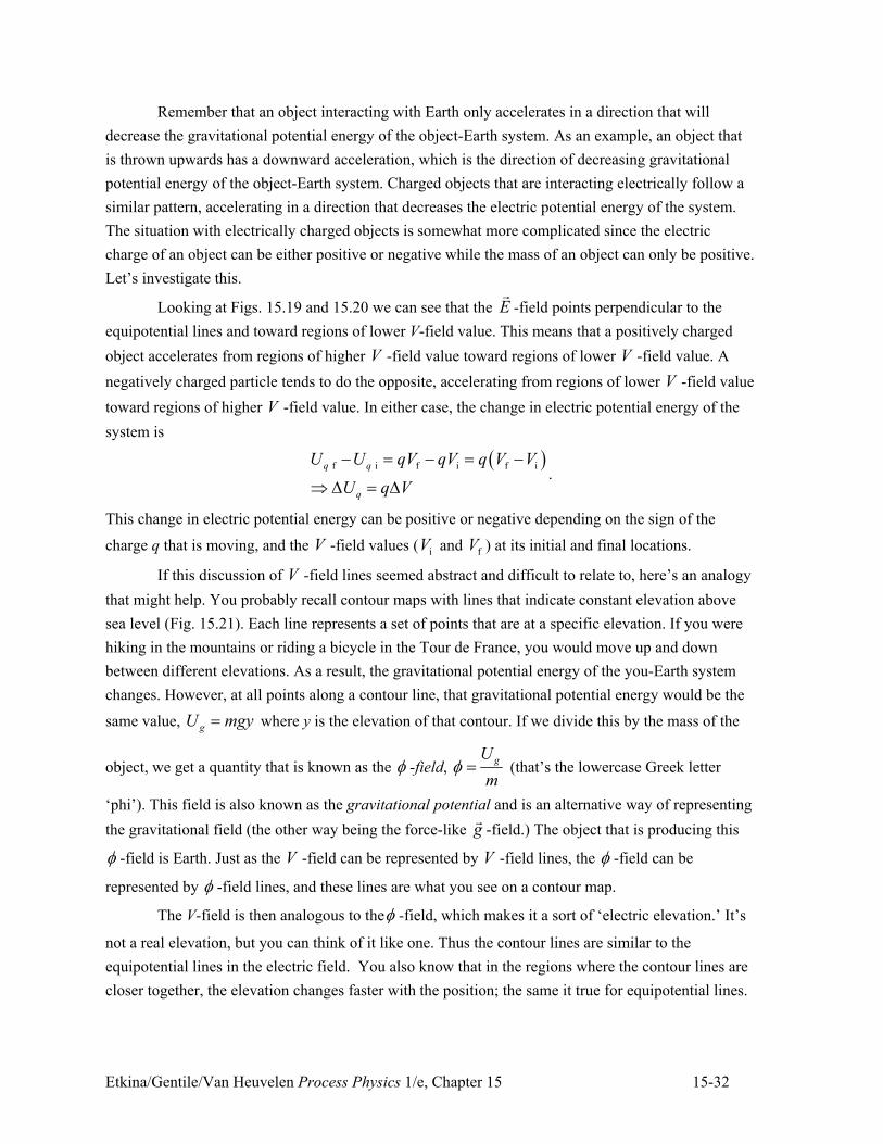
If this discussion of V -field lines seemed abstract and difficult to relate to, here’s an analogy
that might help. You probably recall contour maps with lines that indicate constant elevation above
sea level (Fig. 15.21). Each line represents a set of points that are at a specific elevation. If you were
hiking in the mountains or riding a bicycle in the Tour de France, you would move up and down
between different elevations. As a result, the gravitational potential energy of the you-Earth system
changes. However, at all points along a contour line, that gravitational potential energy would be the
same value, gU mgy" where y is the elevation of that contour. If we divide this by the mass of the
object, we get a quantity that is known as the 5 -field, gU
m5 " (that’s the lowercase Greek letter
‘phi’). This field is also known as the gravitational potential and is an alternative way of representing
the gravitational field (the other way being the force-like g!
-field.) The object that is producing this
5 -field is Earth. Just as the V -field can be represented by V -field lines, the 5 -field can be
represented by 5 -field lines, and these lines are what you see on a contour map.
The V-field is then analogous to the5 -field, which makes it a sort of ‘electric elevation.’ It’s
not a real elevation, but you can think of it like one. Thus the contour lines are similar to the
equipotential lines in the electric field. You also know that in the regions where the contour lines are
closer together, the elevation changes faster with the position; the same it true for equipotential lines.
Etkina/Gentile/Van Heuvelen Process Physics 1/e, Chapter 15 15-33
Figure 15.21 Constant elevation contour lines
We learned that positively charged objects accelerate from regions of higher V -field value
toward regions of lower V -field value. Referring to the analogy, this would be the ‘downhill’
direction. For negatively charged objects the analogy is a bit strange. Imagine what would happen if
an object existed with negative mass. The gravitational field would exert a force on this object in the
opposite direction. It would accelerate upward away from Earth! Physicists do not have any evidence
for the existence of negative mass objects, but there most certainly exist objects with negative electric
charge. This means that negatively charged objects will accelerate in the ‘uphill’ direction in our
analogy, from regions of low V -field value to high V-field value.
Review question 15.5
You want to move a small positively charged object in a circular path around a charged aluminum foil
ball. What work is done when you move 1/4 of the circumference compared to moving 1/2 of the
circumference (you are moving the charged object very slowly, so disregard its change in kinetic
energy)?
15.6 Skills analyzing processes using V-Field approach
The skills for using work-energy ideas to analyze processes involving the electric interaction
are similar to the skills learned in Chapter 6 for analyzing mechanical processes. These skills are
described and illustrated in the following problem.
Example 15.8 X-ray machine In an X-ray machine there is a wire (called a filament) which, when
hot, ejects electrons (we will learn more about this process in Chapter 26). Imagine one of those
electrons that is now outside the wire, starts at rest and accelerates through a region where the V-field
increases by 40,000 V (also called a +40,000 V potential difference.) The electron stops abruptly
when it hits a piece of tungsten at the other side of the region, producing X-rays (more about that in
Chapter 26.) How fast is the electron moving just before it reaches the tungsten?
Etkina/Gentile/Van Heuvelen Process Physics 1/e, Chapter 15 15-34
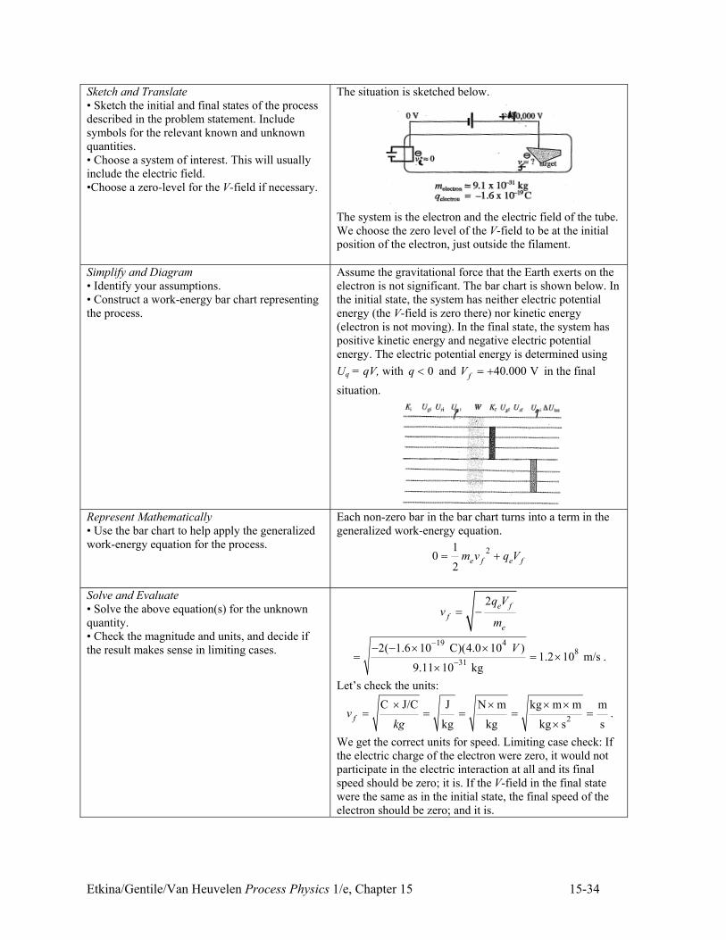
Sketch and Translate
• Sketch the initial and final states of the process
described in the problem statement. Include
symbols for the relevant known and unknown
quantities.
• Choose a system of interest. This will usually
include the electric field.
•Choose a zero-level for the V-field if necessary.
The situation is sketched below.
The system is the electron and the electric field of the tube.
We choose the zero level of the V-field to be at the initial
position of the electron, just outside the filament.
Simplify and Diagram
• Identify your assumptions.
• Construct a work-energy bar chart representing
the process.
Assume the gravitational force that the Earth exerts on the
electron is not significant. The bar chart is shown below. In
the initial state, the system has neither electric potential
energy (the V-field is zero there) nor kinetic energy
(electron is not moving). In the final state, the system has
positive kinetic energy and negative electric potential
energy. The electric potential energy is determined using
Uq = qV, with 0q 6 and 40.000 VfV " . in the final
situation.
Represent Mathematically
• Use the bar chart to help apply the generalized
work-energy equation for the process.
Each non-zero bar in the bar chart turns into a term in the
generalized work-energy equation.
210
2e f e fm v q V" .
Solve and Evaluate
• Solve the above equation(s) for the unknown
quantity.
• Check the magnitude and units, and decide if
the result makes sense in limiting cases.
2
f
e f
e
q Vv
m" +
19 48
31
2( 1.6 10 C)(4.0 10 )1.2 10 m/s
9.11 10 kg
V+
+
+ + , ," " ,
,.
Let’s check the units:
2
C J/C J N m kg m m m
kg kg kg s sfv
kg
, , , ," " " " "
,.
We get the correct units for speed. Limiting case check: If
the electric charge of the electron were zero, it would not
participate in the electric interaction at all and its final
speed should be zero; it is. If the V-field in the final state
were the same as in the initial state, the final speed of the
electron should be zero; and it is.
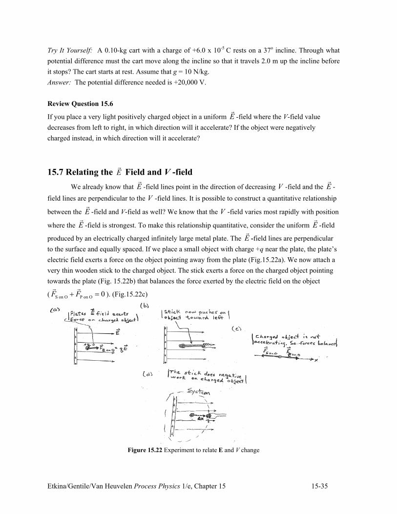
Etkina/Gentile/Van Heuvelen Process Physics 1/e, Chapter 15 15-35
Try It Yourself: A 0.10-kg cart with a charge of +6.0 x 10⁻⁵ C rests on a 37o incline. Through what
potential difference must the cart move along the incline so that it travels 2.0 m up the incline before
it stops? The cart starts at rest. Assume that g = 10 N/kg.
Answer: The potential difference needed is +20,000 V.
Review Question 15.6
If you place a very light positively charged object in a uniform E!
-field where the V-field value
decreases from left to right, in which direction will it accelerate? If the object were negatively
charged instead, in which direction will it accelerate?
15.7 Relating the E!
Field and V -field
We already know that E!
-field lines point in the direction of decreasing V -field and the E!
-
field lines are perpendicular to the V -field lines. It is possible to construct a quantitative relationship
between the E!
-field and V-field as well? We know that the V -field varies most rapidly with position
where the E!
-field is strongest. To make this relationship quantitative, consider the uniform E!
-field
produced by an electrically charged infinitely large metal plate. The E!
-field lines are perpendicular
to the surface and equally spaced. If we place a small object with charge +q near the plate, the plate’s
electric field exerts a force on the object pointing away from the plate (Fig.15.22a). We now attach a
very thin wooden stick to the charged object. The stick exerts a force on the charged object pointing
towards the plate (Fig. 15.22b) that balances the force exerted by the electric field on the object
( S on O P on O 0F F. "! !
). (Fig.15.22c)
Figure 15.22 Experiment to relate E and V change
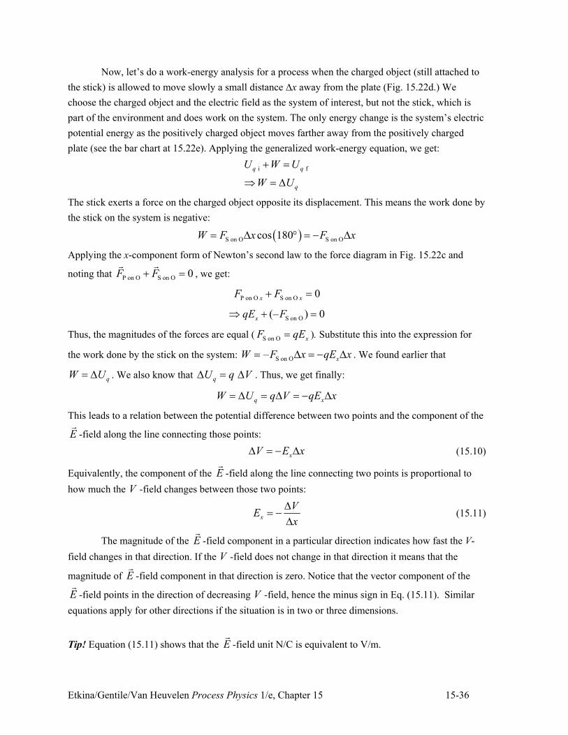
Etkina/Gentile/Van Heuvelen Process Physics 1/e, Chapter 15 15-36
Now, let’s do a work-energy analysis for a process when the charged object (still attached to
the stick) is allowed to move slowly a small distance !x away from the plate (Fig. 15.22d.) We
choose the charged object and the electric field as the system of interest, but not the stick, which is
part of the environment and does work on the system. The only energy change is the system’s electric
potential energy as the positively charged object moves farther away from the positively charged
plate (see the bar chart at 15.22e). Applying the generalized work-energy equation, we get:
i fq q
q
U W U
W U
. "
/ " 2
The stick exerts a force on the charged object opposite its displacement. This means the work done by
the stick on the system is negative:
) *S on O S on Ocos 180W F x F x" 2 1 " + 2
Applying the x-component form of Newton’s second law to the force diagram in Fig. 15.22c and
noting that P on O S on O 0F F. "! !
, we get:
P on O S on O 0x xF F. "
S on O(– ) 0xqE F/ . "
Thus, the magnitudes of the forces are equal ( S on O xF qE" ). Substitute this into the expression for
the work done by the stick on the system: S on O– xW F x qE x" 2 " + 2 . We found earlier that
qW U" 2 . We also know that qU q V2 " 2 . Thus, we get finally:
q xW U q V qE x" 2 " 2 " + 2
This leads to a relation between the potential difference between two points and the component of the
E!
-field along the line connecting those points:
xV E x2 " + 2 (15.10)
Equivalently, the component of the E!
-field along the line connecting two points is proportional to
how much the V -field changes between those two points:
x
VE
x
2" +
2 (15.11)
The magnitude of the E!
-field component in a particular direction indicates how fast the V-
field changes in that direction. If the V -field does not change in that direction it means that the
magnitude of E!
-field component in that direction is zero. Notice that the vector component of the
E!
-field points in the direction of decreasing V -field, hence the minus sign in Eq. (15.11). Similar
equations apply for other directions if the situation is in two or three dimensions.
Tip! Equation (15.11) shows that the E!
-field unit N/C is equivalent to V/m.
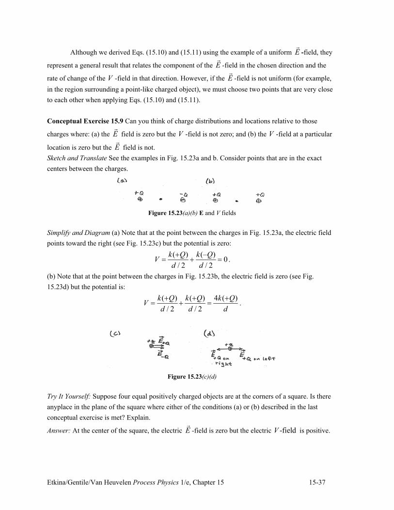
Etkina/Gentile/Van Heuvelen Process Physics 1/e, Chapter 15 15-37
Although we derived Eqs. (15.10) and (15.11) using the example of a uniform E!
-field, they
represent a general result that relates the component of the E!
-field in the chosen direction and the
rate of change of the V -field in that direction. However, if the E!
-field is not uniform (for example,
in the region surrounding a point-like charged object), we must choose two points that are very close
to each other when applying Eqs. (15.10) and (15.11).
Conceptual Exercise 15.9 Can you think of charge distributions and locations relative to those
charges where: (a) the E!
field is zero but the V -field is not zero; and (b) the V -field at a particular
location is zero but the E!
field is not.
Sketch and Translate See the examples in Fig. 15.23a and b. Consider points that are in the exact
centers between the charges.
Figure 15.23(a)(b) E and V fields
Simplify and Diagram (a) Note that at the point between the charges in Fig. 15.23a, the electric field
points toward the right (see Fig. 15.23c) but the potential is zero:
( ) (– )0
/ 2 / 2
k Q k QV
d d
." . " .
(b) Note that at the point between the charges in Fig. 15.23b, the electric field is zero (see Fig.
15.23d) but the potential is:
( ) ( ) 4 ( )
/ 2 / 2
k Q k Q k QV
d d d
. . ." . " .
Figure 15.23(c)(d)
Try It Yourself: Suppose four equal positively charged objects are at the corners of a square. Is there
anyplace in the plane of the square where either of the conditions (a) or (b) described in the last
conceptual exercise is met? Explain.
Answer: At the center of the square, the electric E!
-field is zero but the electric -fieldV is positive.
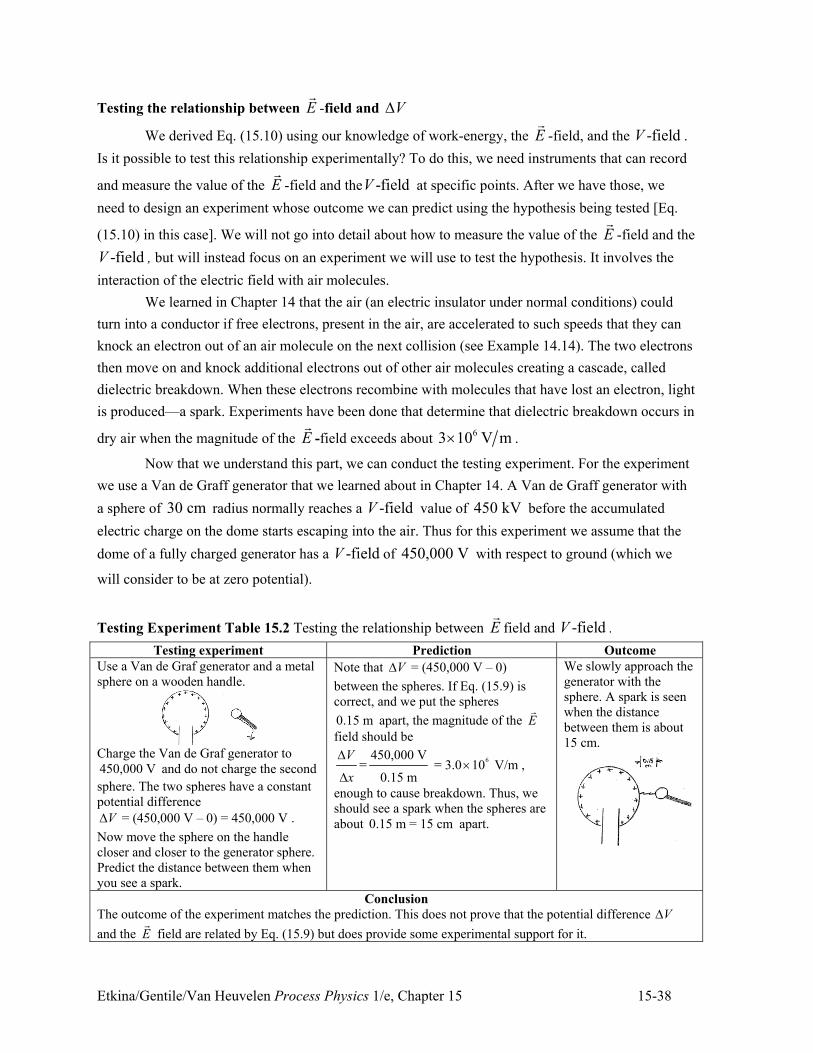
Etkina/Gentile/Van Heuvelen Process Physics 1/e, Chapter 15 15-38
Testing the relationship between E!
-field and V2
We derived Eq. (15.10) using our knowledge of work-energy, the E!
-field, and the -fieldV .
Is it possible to test this relationship experimentally? To do this, we need instruments that can record
and measure the value of the E!
-field and the -fieldV at specific points. After we have those, we
need to design an experiment whose outcome we can predict using the hypothesis being tested [Eq.
(15.10) in this case]. We will not go into detail about how to measure the value of the E!
-field and the
-fieldV , but will instead focus on an experiment we will use to test the hypothesis. It involves the
interaction of the electric field with air molecules.
We learned in Chapter 14 that the air (an electric insulator under normal conditions) could
turn into a conductor if free electrons, present in the air, are accelerated to such speeds that they can
knock an electron out of an air molecule on the next collision (see Example 14.14). The two electrons
then move on and knock additional electrons out of other air molecules creating a cascade, called
dielectric breakdown. When these electrons recombine with molecules that have lost an electron, light
is produced—a spark. Experiments have been done that determine that dielectric breakdown occurs in
dry air when the magnitude of the E!
-field exceeds about 63 10 V m, .
Now that we understand this part, we can conduct the testing experiment. For the experiment
we use a Van de Graff generator that we learned about in Chapter 14. A Van de Graff generator with
a sphere of 30 cm radius normally reaches a -fieldV value of 450 kV before the accumulated
electric charge on the dome starts escaping into the air. Thus for this experiment we assume that the
dome of a fully charged generator has a -fieldV of 450,000 V with respect to ground (which we
will consider to be at zero potential).
Testing Experiment Table 15.2 Testing the relationship between E!
field and -fieldV .
Testing experiment Prediction Outcome
Use a Van de Graf generator and a metal
sphere on a wooden handle.
Charge the Van de Graf generator to
450,000 V and do not charge the second
sphere. The two spheres have a constant
potential difference
= (450,000 V – 0) = 450,000 VV2 .
Now move the sphere on the handle
closer and closer to the generator sphere.
Predict the distance between them when
you see a spark.
Note that = (450,000 V – 0)V2
between the spheres. If Eq. (15.9) is
correct, and we put the spheres
0.15 m apart, the magnitude of the E!
field should be
6450,000 V= = 3.0 10 V/m
0.15 m
V
x
2,
2,
enough to cause breakdown. Thus, we
should see a spark when the spheres are
about 0.15 m = 15 cm apart.
We slowly approach the
generator with the
sphere. A spark is seen
when the distance
between them is about
15 cm.
Conclusion
The outcome of the experiment matches the prediction. This does not prove that the potential difference V2
and the E!
field are related by Eq. (15.9) but does provide some experimental support for it.
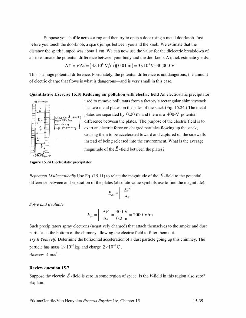
Etkina/Gentile/Van Heuvelen Process Physics 1/e, Chapter 15 15-39
Suppose you shuffle across a rug and then try to open a door using a metal doorknob. Just
before you touch the doorknob, a spark jumps between you and the knob. We estimate that the
distance the spark jumped was about 1 cm. We can now use the value for the dielectric breakdown of
air to estimate the potential difference between your body and the doorknob. A quick estimate yields:
) *) *6 43 10 V m 0.01 m 3 10 V=30,000 VV E x2 " 2 " , " ,
This is a huge potential difference. Fortunately, the potential difference is not dangerous; the amount
of electric charge that flows is what is dangerous—and is very small in this case.
Quantitative Exercise 15.10 Reducing air pollution with electric field An electrostatic precipitator
used to remove pollutants from a factory’s rectangular chimneystack
has two metal plates on the sides of the stack (Fig. 15.24.) The metal
plates are separated by 0.20 m and there is a 400-V potential
difference between the plates. The purpose of the electric field is to
exert an electric force on charged particles flowing up the stack,
causing them to be accelerated toward and captured on the sidewalls
instead of being released into the environment. What is the average
magnitude of the E!
-field between the plates?
Figure 15.24 Electrostatic precipitator
Represent Mathematically Use Eq. (15.11) to relate the magnitude of the E!
-field to the potential
difference between and separation of the plates (absolute value symbols use to find the magnitude):
av
VE
s
2" +
2
Solve and Evaluate
400 V2000 V/m
0.2 mav
VE
s
2" + " "
2
Such precipitators spray electrons (negatively charged) that attach themselves to the smoke and dust
particles at the bottom of the chimney allowing the electric field to filter them out.
Try It Yourself: Determine the horizontal acceleration of a dust particle going up this chimney. The
particle has mass 61 10 kg+, and charge
92 10 C+, .
Answer: 4 m/s2.
Review question 15.7
Suppose the electric E!
-field is zero in some region of space. Is the V-field in this region also zero?
Explain.
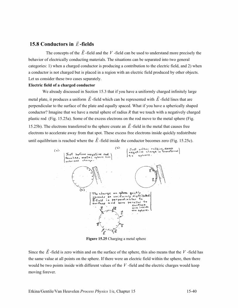
Etkina/Gentile/Van Heuvelen Process Physics 1/e, Chapter 15 15-40
15.8 Conductors in E!
-fields
The concepts of the E!
-field and the V -field can be used to understand more precisely the
behavior of electrically conducting materials. The situations can be separated into two general
categories: 1) when a charged conductor is producing a contribution to the electric field, and 2) when
a conductor is not charged but is placed in a region with an electric field produced by other objects.
Let us consider these two cases separately.
Electric field of a charged conductor
We already discussed in Section 15.3 that if you have a uniformly charged infinitely large
metal plate, it produces a uniform E!
-field which can be represented with E!
-field lines that are
perpendicular to the surface of the plate and equally spaced. What if you have a spherically shaped
conductor? Imagine that we have a metal sphere of radius R that we touch with a negatively charged
plastic rod (Fig. 15.25a). Some of the excess electrons on the rod move to the metal sphere (Fig.
15.25b). The electrons transferred to the sphere create an E!
-field in the metal that causes free
electrons to accelerate away from that spot. These excess free electrons inside quickly redistribute
until equilibrium is reached where the E!
-field inside the conductor becomes zero (Fig. 15.25c).
Figure 15.25 Charging a metal sphere
Since the E!
-field is zero within and on the surface of the sphere, this also means that the V -field has
the same value at all points on the sphere. If there were an electric field within the sphere, then there
would be two points inside with different values of the V -field and the electric charges would keep
moving forever.
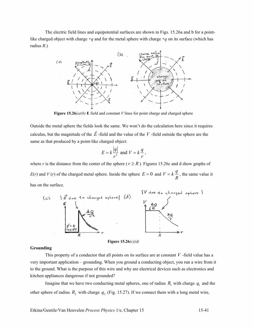
Etkina/Gentile/Van Heuvelen Process Physics 1/e, Chapter 15 15-41
The electric field lines and equipotential surfaces are shown in Figs. 15.26a and b for a point-
like charged object with charge +q and for the metal sphere with charge +q on its surface (which has
radius R.)
Figure 15.26(a)(b) E field and constant V lines for point charge and charged sphere
Outside the metal sphere the fields look the same. We won’t do the calculation here since it requires
calculus, but the magnitude of the E!
-field and the value of the V -field outside the sphere are the
same as that produced by a point-like charged object:
2 and
q qE k V k
r r" " ,
where r is the distance from the center of the sphere ( r R7 ). Figures 15.26c and d show graphs of
E(r) and V (r) of the charged metal sphere. Inside the sphere 0E " and q
V kR
" , the same value it
has on the surface.
Figure 15.26(c)(d)
Grounding
This property of a conductor that all points on its surface are at constant V -field value has a
very important application – grounding. When you ground a conducting object, you run a wire from it
to the ground. What is the purpose of this wire and why are electrical devices such as electronics and
kitchen appliances dangerous if not grounded?
Imagine that we have two conducting metal spheres, one of radius 1R with charge 1q and the
other sphere of radius 2R with charge 2q (Fig. 15.27). If we connect them with a long metal wire,
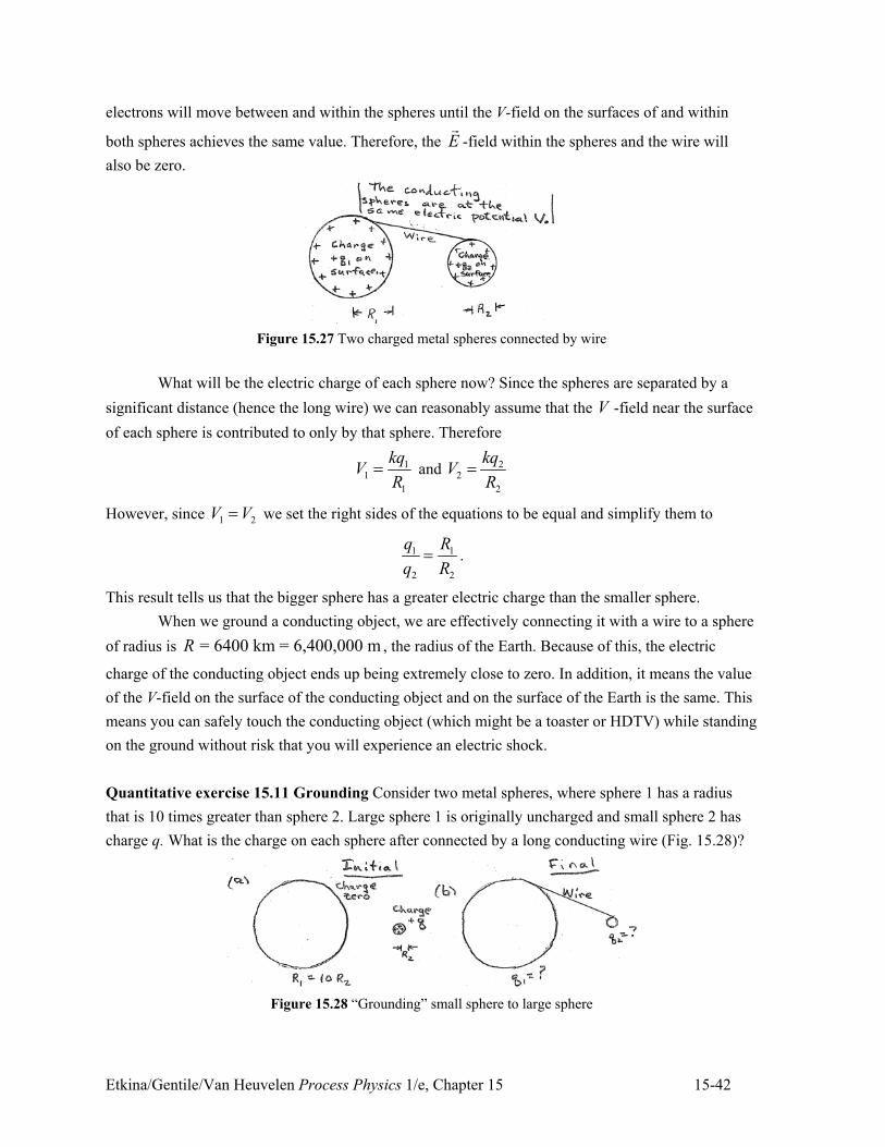
Etkina/Gentile/Van Heuvelen Process Physics 1/e, Chapter 15 15-42
electrons will move between and within the spheres until the V-field on the surfaces of and within
both spheres achieves the same value. Therefore, the E!
-field within the spheres and the wire will
also be zero.
Figure 15.27 Two charged metal spheres connected by wire
What will be the electric charge of each sphere now? Since the spheres are separated by a
significant distance (hence the long wire) we can reasonably assume that the V -field near the surface
of each sphere is contributed to only by that sphere. Therefore
11
1
kqV
R" and 2
2
2
kqV
R"
However, since 1 2V V" we set the right sides of the equations to be equal and simplify them to
1 1
2 2
q R
q R" .
This result tells us that the bigger sphere has a greater electric charge than the smaller sphere.
When we ground a conducting object, we are effectively connecting it with a wire to a sphere
of radius is = 6400 km = 6,400,000 mR , the radius of the Earth. Because of this, the electric
charge of the conducting object ends up being extremely close to zero. In addition, it means the value
of the V-field on the surface of the conducting object and on the surface of the Earth is the same. This
means you can safely touch the conducting object (which might be a toaster or HDTV) while standing
on the ground without risk that you will experience an electric shock.
Quantitative exercise 15.11 Grounding Consider two metal spheres, where sphere 1 has a radius
that is 10 times greater than sphere 2. Large sphere 1 is originally uncharged and small sphere 2 has
charge q. What is the charge on each sphere after connected by a long conducting wire (Fig. 15.28)?
Figure 15.28 “Grounding” small sphere to large sphere
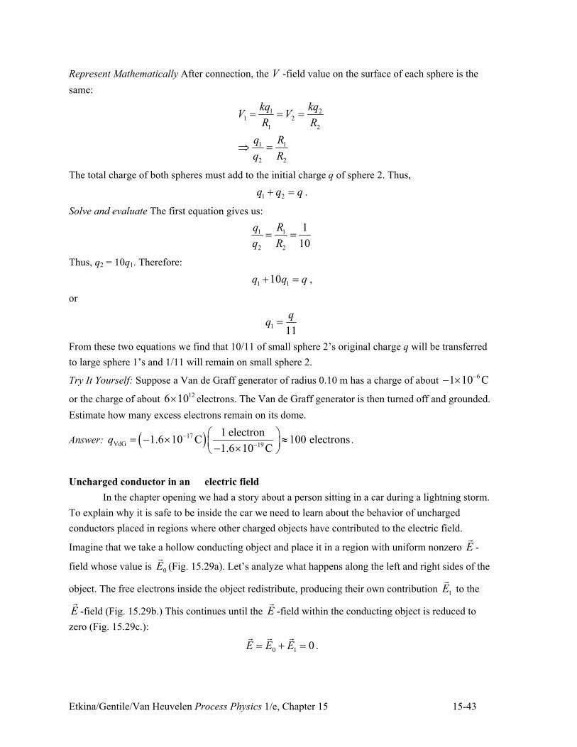
Etkina/Gentile/Van Heuvelen Process Physics 1/e, Chapter 15 15-43
Represent Mathematically After connection, the V -field value on the surface of each sphere is the
same:
1 21 2
1 2
1 1
2 2
kq kqV V
R R
q R
q R
" " "
/ "
The total charge of both spheres must add to the initial charge q of sphere 2. Thus,
1 2q q q. " .
Solve and evaluate The first equation gives us:
1 1
2 2
1
10
q R
q R" "
Thus, q2 = 10q1. Therefore:
1 110q q q. " ,
or
111
qq "
From these two equations we find that 10/11 of small sphere 2’s original charge q will be transferred
to large sphere 1’s and 1/11 will remain on small sphere 2.
Try It Yourself: Suppose a Van de Graff generator of radius 0.10 m has a charge of about 61 10 C++ ,
or the charge of about 126 10, electrons. The Van de Graff generator is then turned off and grounded.
Estimate how many excess electrons remain on its dome.
Answer: ) *17
VdG 19
1 electron1.6 10 C 100 electrons
1.6 10 Cq +
+
# $" + , 8% &+ ,' (.
Uncharged conductor in an electric field
In the chapter opening we had a story about a person sitting in a car during a lightning storm.
To explain why it is safe to be inside the car we need to learn about the behavior of uncharged
conductors placed in regions where other charged objects have contributed to the electric field.
Imagine that we take a hollow conducting object and place it in a region with uniform nonzero E!
-
field whose value is 0E!
(Fig. 15.29a). Let’s analyze what happens along the left and right sides of the
object. The free electrons inside the object redistribute, producing their own contribution 1E!
to the
E!
-field (Fig. 15.29b.) This continues until the E!
-field within the conducting object is reduced to
zero (Fig. 15.29c.):
0 1 0E E E" . "! ! !
.
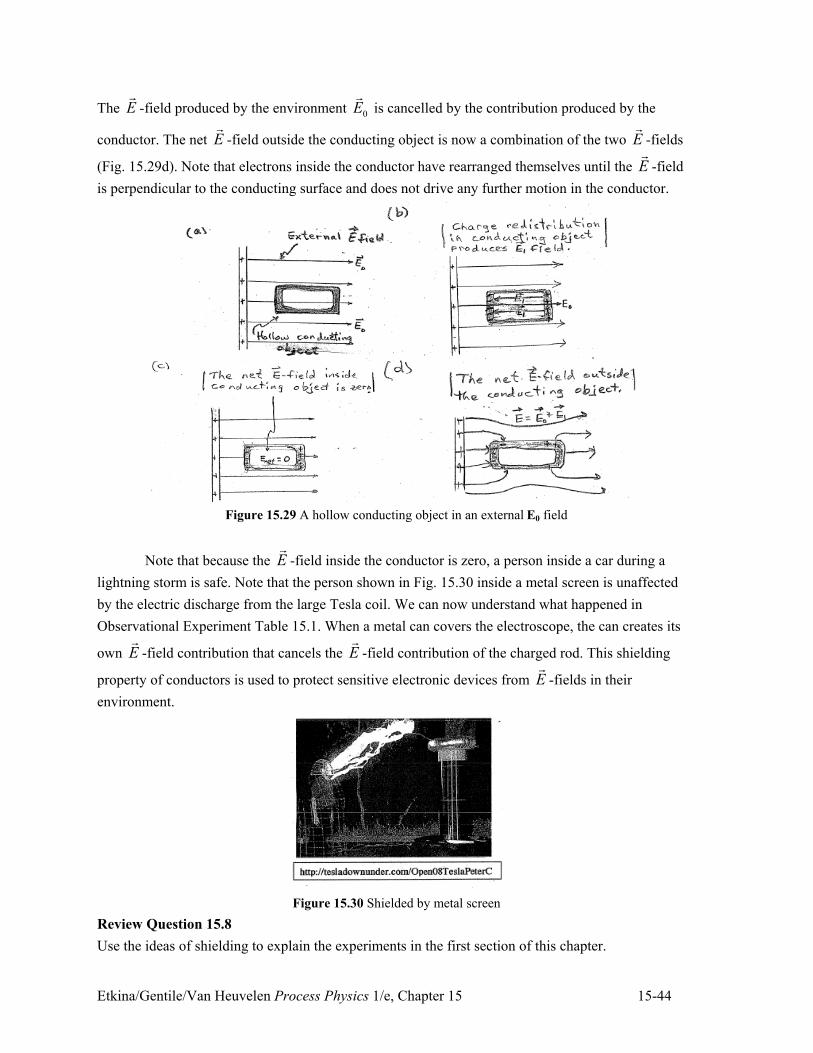
Etkina/Gentile/Van Heuvelen Process Physics 1/e, Chapter 15 15-44
The E!
-field produced by the environment 0E!
is cancelled by the contribution produced by the
conductor. The net E!
-field outside the conducting object is now a combination of the two E!
-fields
(Fig. 15.29d). Note that electrons inside the conductor have rearranged themselves until the E!
-field
is perpendicular to the conducting surface and does not drive any further motion in the conductor.
Figure 15.29 A hollow conducting object in an external E0 field
Note that because the E!
-field inside the conductor is zero, a person inside a car during a
lightning storm is safe. Note that the person shown in Fig. 15.30 inside a metal screen is unaffected
by the electric discharge from the large Tesla coil. We can now understand what happened in
Observational Experiment Table 15.1. When a metal can covers the electroscope, the can creates its
own E!
-field contribution that cancels the E!
-field contribution of the charged rod. This shielding
property of conductors is used to protect sensitive electronic devices from E!
-fields in their
environment.
Figure 15.30 Shielded by metal screen
Review Question 15.8
Use the ideas of shielding to explain the experiments in the first section of this chapter.
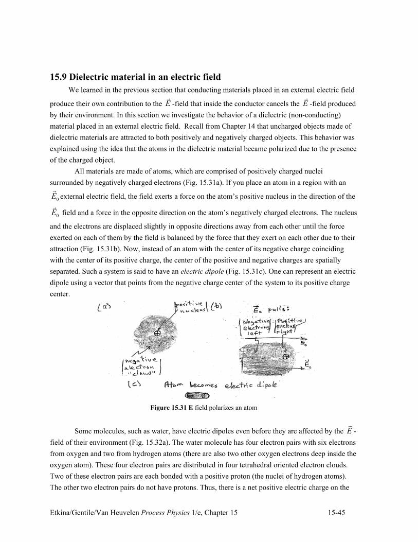
Etkina/Gentile/Van Heuvelen Process Physics 1/e, Chapter 15 15-45
15.9 Dielectric material in an electric field
We learned in the previous section that conducting materials placed in an external electric field
produce their own contribution to the E!
-field that inside the conductor cancels the E!
-field produced
by their environment. In this section we investigate the behavior of a dielectric (non-conducting)
material placed in an external electric field. Recall from Chapter 14 that uncharged objects made of
dielectric materials are attracted to both positively and negatively charged objects. This behavior was
explained using the idea that the atoms in the dielectric material became polarized due to the presence
of the charged object.
All materials are made of atoms, which are comprised of positively charged nuclei
surrounded by negatively charged electrons (Fig. 15.31a). If you place an atom in a region with an
0E!
external electric field, the field exerts a force on the atom’s positive nucleus in the direction of the
0E!
field and a force in the opposite direction on the atom’s negatively charged electrons. The nucleus
and the electrons are displaced slightly in opposite directions away from each other until the force
exerted on each of them by the field is balanced by the force that they exert on each other due to their
attraction (Fig. 15.31b). Now, instead of an atom with the center of its negative charge coinciding
with the center of its positive charge, the center of the positive and negative charges are spatially
separated. Such a system is said to have an electric dipole (Fig. 15.31c). One can represent an electric
dipole using a vector that points from the negative charge center of the system to its positive charge
center.
Figure 15.31 E field polarizes an atom
Some molecules, such as water, have electric dipoles even before they are affected by the E!
-
field of their environment (Fig. 15.32a). The water molecule has four electron pairs with six electrons
from oxygen and two from hydrogen atoms (there are also two other oxygen electrons deep inside the
oxygen atom). These four electron pairs are distributed in four tetrahedral oriented electron clouds.
Two of these electron pairs are each bonded with a positive proton (the nuclei of hydrogen atoms).
The other two electron pairs do not have protons. Thus, there is a net positive electric charge on the
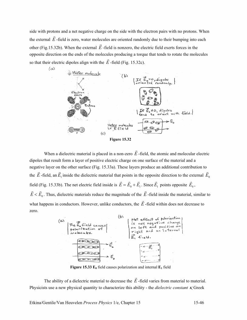
Etkina/Gentile/Van Heuvelen Process Physics 1/e, Chapter 15 15-46
side with protons and a net negative charge on the side with the electron pairs with no protons. When
the external E!
-field is zero, water molecules are oriented randomly due to their bumping into each
other (Fig.15.32b). When the external E!
-field is nonzero, the electric field exerts forces in the
opposite direction on the ends of the molecules producing a torque that tends to rotate the molecules
so that their electric dipoles align with the E!
-field (Fig. 15.32c).
(c)
Figure 15.32
When a dielectric material is placed in a non-zero E!
-field, the atomic and molecular electric
dipoles that result form a layer of positive electric charge on one surface of the material and a
negative layer on the other surface (Fig. 15.33a). These layers produce an additional contribution to
the E!
-field, an 1E!
inside the dielectric material that points in the opposite direction to the external 0E!
field (Fig. 15.33b). The net electric field inside is 0 1E E E" .! ! !
. Since 1E!
points opposite 0E!
,
0E E6! !
. Thus, dielectric materials reduce the magnitude of the E!
-field inside the material, similar to
what happens in conductors. However, unlike conductors, the E!
-field within does not decrease to
zero.
Figure 15.33 E0 field causes polarization and internal E1 field
The ability of a dielectric material to decrease the E!
-field varies from material to material.
Physicists use a new physical quantity to characterize this ability - the dielectric constant 9 "Greek
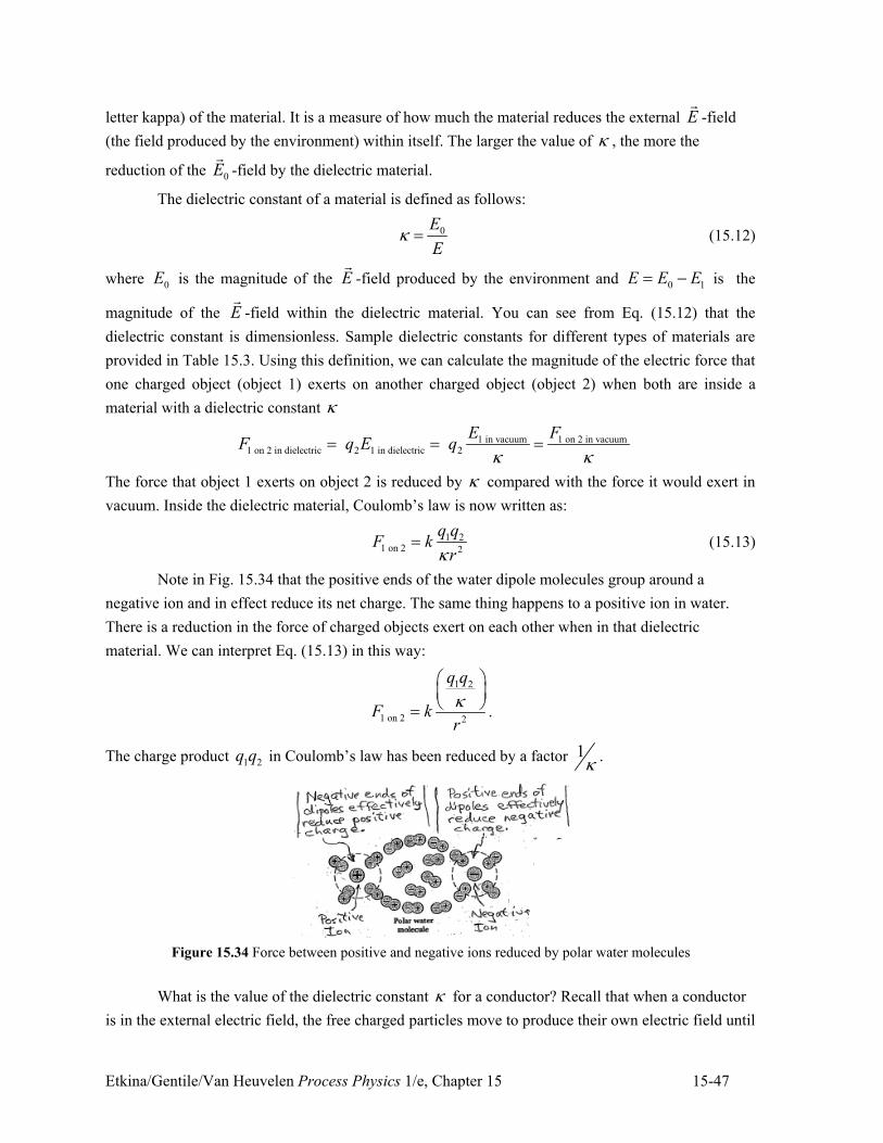
Etkina/Gentile/Van Heuvelen Process Physics 1/e, Chapter 15 15-47
letter kappa) of the material. It is a measure of how much the material reduces the external E!
-field
(the field produced by the environment) within itself. The larger the value of 9 , the more the
reduction of the 0E!
-field by the dielectric material.
The dielectric constant of a material is defined as follows:
0E
E9 " (15.12)
where 0E is the magnitude of the E!
-field produced by the environment and 0 1E E E" + is the
magnitude of the E!
-field within the dielectric material. You can see from Eq. (15.12) that the
dielectric constant is dimensionless. Sample dielectric constants for different types of materials are
provided in Table 15.3. Using this definition, we can calculate the magnitude of the electric force that
one charged object (object 1) exerts on another charged object (object 2) when both are inside a
material with a dielectric constant 9
1 in vacuum 1 on 2 in vacuum1 on 2 in dielectric 2 1 in dielectric 2
E FF q E q
9 9" " "
The force that object 1 exerts on object 2 is reduced by 9 compared with the force it would exert in
vacuum. Inside the dielectric material, Coulomb’s law is now written as:
1 21 on 2 2
q qF k
r9" (15.13)
Note in Fig. 15.34 that the positive ends of the water dipole molecules group around a
negative ion and in effect reduce its net charge. The same thing happens to a positive ion in water.
There is a reduction in the force of charged objects exert on each other when in that dielectric
material. We can interpret Eq. (15.13) in this way:
1 2
1 on 2 2
q q
F kr
9# $% &' (" .
The charge product 1 2q q in Coulomb’s law has been reduced by a factor 19 .
Figure 15.34 Force between positive and negative ions reduced by polar water molecules
What is the value of the dielectric constant 9 for a conductor? Recall that when a conductor
is in the external electric field, the free charged particles move to produce their own electric field until
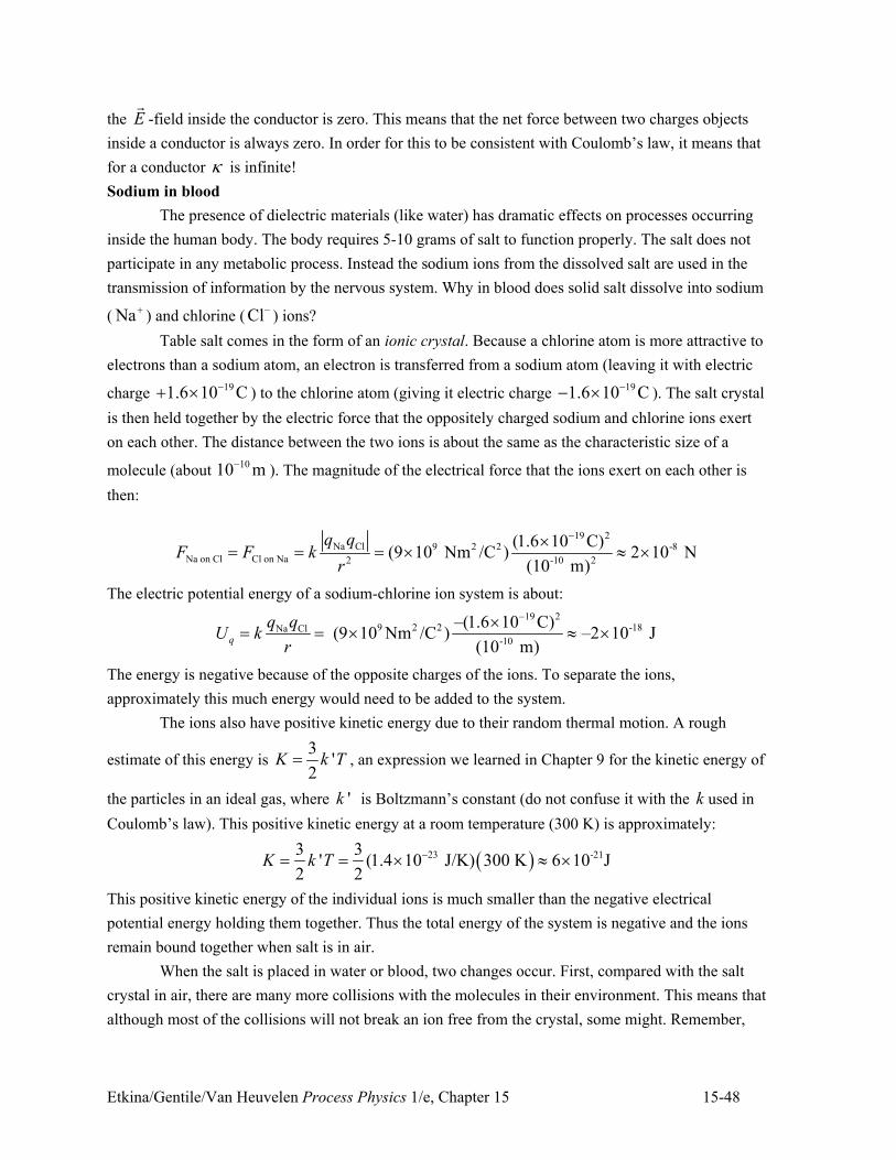
Etkina/Gentile/Van Heuvelen Process Physics 1/e, Chapter 15 15-48
the E!
-field inside the conductor is zero. This means that the net force between two charges objects
inside a conductor is always zero. In order for this to be consistent with Coulomb’s law, it means that
for a conductor 9 is infinite!
Sodium in blood
The presence of dielectric materials (like water) has dramatic effects on processes occurring
inside the human body. The body requires 5-10 grams of salt to function properly. The salt does not
participate in any metabolic process. Instead the sodium ions from the dissolved salt are used in the
transmission of information by the nervous system. Why in blood does solid salt dissolve into sodium
( Na.) and chlorine ( Cl+ ) ions?
Table salt comes in the form of an ionic crystal. Because a chlorine atom is more attractive to
electrons than a sodium atom, an electron is transferred from a sodium atom (leaving it with electric
charge 191.6 10 C+. , ) to the chlorine atom (giving it electric charge
191.6 10 C++ , ). The salt crystal
is then held together by the electric force that the oppositely charged sodium and chlorine ions exert
on each other. The distance between the two ions is about the same as the characteristic size of a
molecule (about 1010 m+
). The magnitude of the electrical force that the ions exert on each other is
then:
19 2Na Cl 9 2 2 -8
Na on Cl Cl on Na 2 -10 2
(1.6 10 C)(9 10 Nm /C ) 2 10 N
(10 m)
q qF F k
r
+," " " , 8 ,
The electric potential energy of a sodium-chlorine ion system is about:
19 29 2 2 -18Na Cl
-10
–(1.6 10 C) (9 10 Nm /C ) –2 10 J
(10 m)q
q qU k
r
+," " , 8 ,
The energy is negative because of the opposite charges of the ions. To separate the ions,
approximately this much energy would need to be added to the system.
The ions also have positive kinetic energy due to their random thermal motion. A rough
estimate of this energy is 3
'2
K k T" , an expression we learned in Chapter 9 for the kinetic energy of
the particles in an ideal gas, where 'k is Boltzmann’s constant (do not confuse it with the k used in
Coulomb’s law). This positive kinetic energy at a room temperature (300 K) is approximately:
) *23 -213 3' (1.4 10 J/K) 300 K 6 10 J
2 2K k T +" " , 8 ,
This positive kinetic energy of the individual ions is much smaller than the negative electrical
potential energy holding them together. Thus the total energy of the system is negative and the ions
remain bound together when salt is in air.
When the salt is placed in water or blood, two changes occur. First, compared with the salt
crystal in air, there are many more collisions with the molecules in their environment. This means that
although most of the collisions will not break an ion free from the crystal, some might. Remember,
Etkina/Gentile/Van Heuvelen Process Physics 1/e, Chapter 15 15-49
3'
2K k T" is the average kinetic energy of the molecules. A few molecules will have enough
random kinetic energy to knock an ion free from the crystal during a collision. Second, any ions that
do become separated from the crystal by collisions do not exert nearly as strong an attractive force on
each other because of the dielectric effect of the blood. Assuming the blood can be thought of as
mostly comprised of water, the attractive force that the two ions exert on each other decreases by a
factor of 81, the dielectric constant of water:
2 19 29 2 2 -10
Na on Cl in water 2 -10 2
(1.6 10 C) (9 10 Nm /C ) 3 10 N
81(10 m)
eF k
r9
+," " , 8 , .
The electric potential energy is also smaller by a factor of 81:
2 19 29 2 2 -20
-10
–(1.6 10 C)(9 10 Nm /C ) –3 10 J
81(10 m)q
eU k
r9
++ ," " , 8 , .
This energy is almost the same as the average kinetic energy of the random motion of the water
molecules; thus the total energy of the system becomes zero (sodium and chlorine ions can separate
from each other!). This means that the random kinetic energy of the water molecules is sufficient to
keep the sodium and chlorine ions from recombining. This allows the nervous system to use this freed
sodium ions to transmit information.
Table 15.3 Dielectric Constants for Different Types of Materials
Type of Material Dielectric Constant (9 )
Vacuum 1.0000
Dry air 1.0006
Wax 2.25
Mica 2 – 7
Glass 4 – 7
Benzene 2.28
Paper 3.5
Axon membrane 8
Body tissue 8
Ethanol 26
Methanol 31
Water 81
* At 20 oC.
Review Question 15.9
What is the difference between conducting and dielectric materials when they are placed in a region
with nonzero E!
-field? Explain these differences.
15. 10 Capacitors and Electric Field Energy
We learned about practical applications of conductors in electric fields, such as grounding
and shielding. Another important application involving electric fields and conductors concerns the
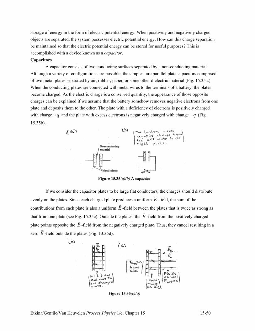
Etkina/Gentile/Van Heuvelen Process Physics 1/e, Chapter 15 15-50
storage of energy in the form of electric potential energy. When positively and negatively charged
objects are separated, the system possesses electric potential energy. How can this charge separation
be maintained so that the electric potential energy can be stored for useful purposes? This is
accomplished with a device known as a capacitor.
Capacitors
A capacitor consists of two conducting surfaces separated by a non-conducting material.
Although a variety of configurations are possible, the simplest are parallel plate capacitors comprised
of two metal plates separated by air, rubber, paper, or some other dielectric material (Fig. 15.35a.)
When the conducting plates are connected with metal wires to the terminals of a battery, the plates
become charged. As the electric charge is a conserved quantity, the appearance of those opposite
charges can be explained if we assume that the battery somehow removes negative electrons from one
plate and deposits them to the other. The plate with a deficiency of electrons is positively charged
with charge q. and the plate with excess electrons is negatively charged with change –q (Fig.
15.35b).
Figure 15.35(a)(b) A capacitor
If we consider the capacitor plates to be large flat conductors, the charges should distribute
evenly on the plates. Since each charged plate produces a uniform E!
-field, the sum of the
contributions from each plate is also a uniform E!
-field between the plates that is twice as strong as
that from one plate (see Fig. 15.35c). Outside the plates, the E!
-field from the positively charged
plate points opposite the E!
-field from the negatively charged plate. Thus, they cancel resulting in a
zero E!
-field outside the plates (Fig. 13.35d).
Figure 15.35(c)(d)
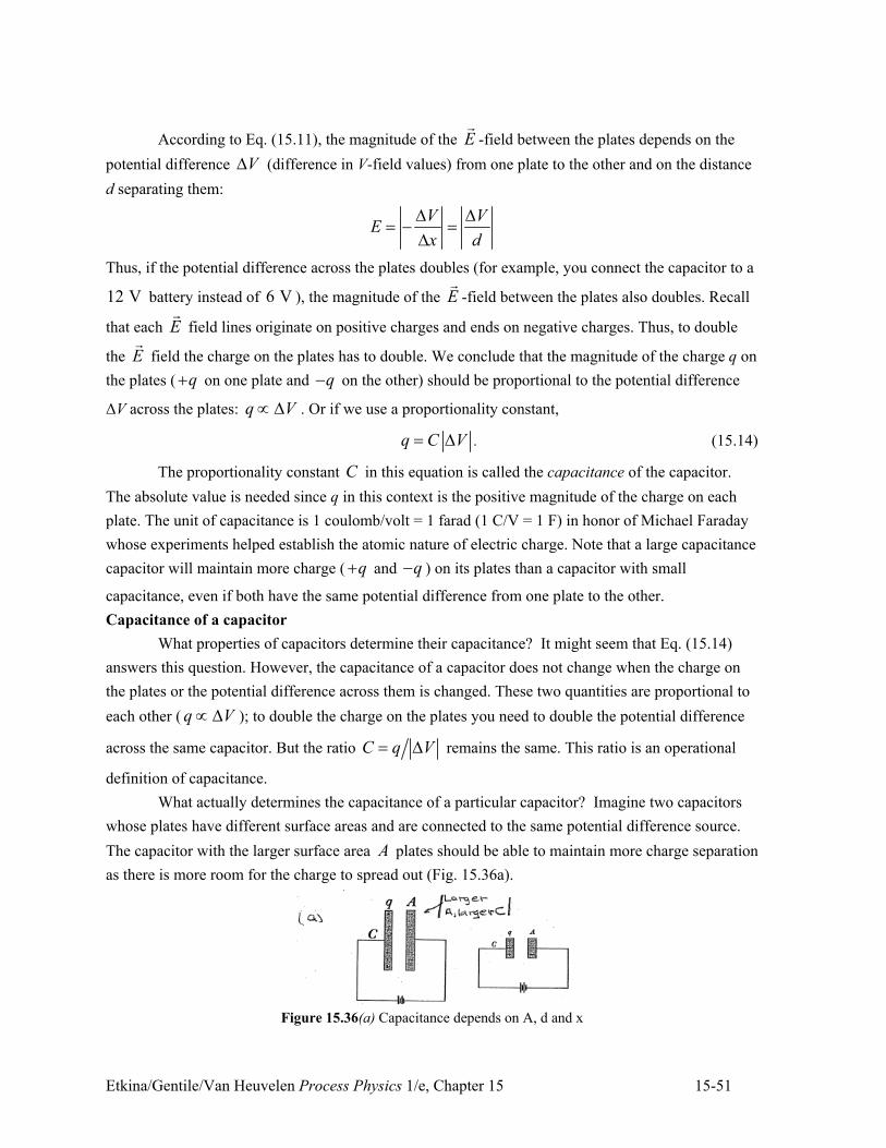
Etkina/Gentile/Van Heuvelen Process Physics 1/e, Chapter 15 15-51
According to Eq. (15.11), the magnitude of the E!
-field between the plates depends on the
potential difference V2 (difference in V-field values) from one plate to the other and on the distance
d separating them:
V VE
x d
2 2" + "
2
Thus, if the potential difference across the plates doubles (for example, you connect the capacitor to a
12 V battery instead of 6 V ), the magnitude of the E!
-field between the plates also doubles. Recall
that each E!
field lines originate on positive charges and ends on negative charges. Thus, to double
the E!
field the charge on the plates has to double. We conclude that the magnitude of the charge q on
the plates ( q. on one plate and q+ on the other) should be proportional to the potential difference
#V across the plates: q V: 2 . Or if we use a proportionality constant,
q C V" 2 . (15.14)
The proportionality constant C in this equation is called the capacitance of the capacitor.
The absolute value is needed since q in this context is the positive magnitude of the charge on each
plate. The unit of capacitance is 1 coulomb/volt = 1 farad (1 C/V = 1 F) in honor of Michael Faraday
whose experiments helped establish the atomic nature of electric charge. Note that a large capacitance
capacitor will maintain more charge ( q. and q+ ) on its plates than a capacitor with small
capacitance, even if both have the same potential difference from one plate to the other.
Capacitance of a capacitor
What properties of capacitors determine their capacitance? It might seem that Eq. (15.14)
answers this question. However, the capacitance of a capacitor does not change when the charge on
the plates or the potential difference across them is changed. These two quantities are proportional to
each other ( q V: 2 ); to double the charge on the plates you need to double the potential difference
across the same capacitor. But the ratio C q V" 2 remains the same. This ratio is an operational
definition of capacitance.
What actually determines the capacitance of a particular capacitor? Imagine two capacitors
whose plates have different surface areas and are connected to the same potential difference source.
The capacitor with the larger surface area A plates should be able to maintain more charge separation
as there is more room for the charge to spread out (Fig. 15.36a).
Figure 15.36(a) Capacitance depends on A, d and x
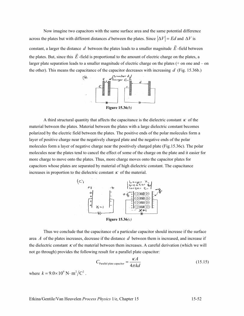
Etkina/Gentile/Van Heuvelen Process Physics 1/e, Chapter 15 15-52
Now imagine two capacitors with the same surface area and the same potential difference
across the plates but with different distances d between the plates. Since V Ed2 " and V2 is
constant, a larger the distance d between the plates leads to a smaller magnitude E!
-field between
the plates. But, since this E!
-field is proportional to the amount of electric charge on the plates, a
larger plate separation leads to a smaller magnitude of electric charge on the plates (+ on one and – on
the other). This means the capacitance of the capacitor decreases with increasing d (Fig. 15.36b.)
Figure 15.36(b)
A third structural quantity that affects the capacitance is the dielectric constant 9 of the
material between the plates. Material between the plates with a large dielectric constant becomes
polarized by the electric field between the plates. The positive ends of the polar molecules form a
layer of positive charge near the negatively charged plate and the negative ends of the polar
molecules form a layer of negative charge near the positively charged plate (Fig.15.36c). The polar
molecules near the plates tend to cancel the effect of some of the charge on the plate and it easier for
more charge to move onto the plates. Thus, more charge moves onto the capacitor plates for
capacitors whose plates are separated by material of high dielectric constant. The capacitance
increases in proportion to the dielectric constant 9 of the material.
Figure 15.36(c)
Thus we conclude that the capacitance of a particular capacitor should increase if the surface
area A of the plates increases, decrease if the distance d between them is increased, and increase if
the dielectric constant 9 of the material between them increases. A careful derivation (which we will
not go through) provides the following result for a parallel plate capacitor:
Parallel plate capacitor4
AC
kd
9;
" (15.15)
where 9 2 29.0 10 N m Ck " , - .
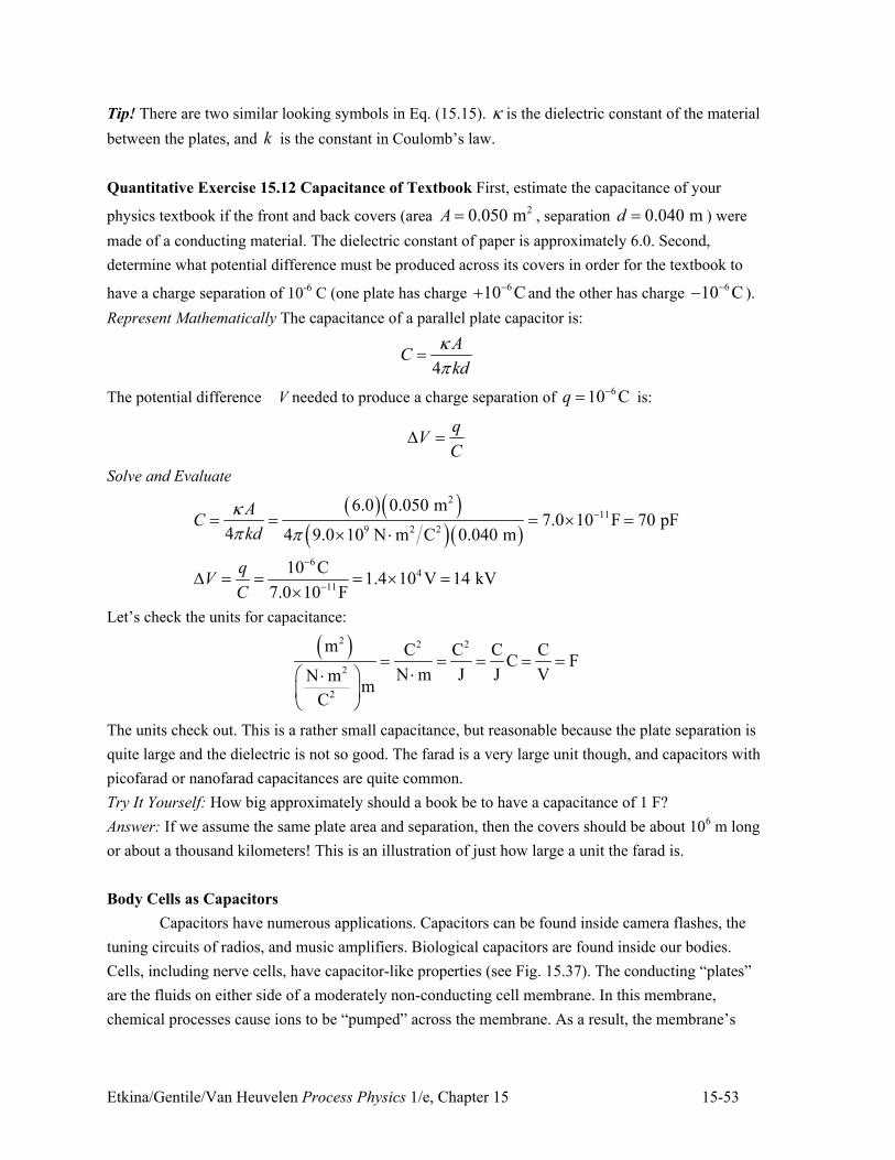
Etkina/Gentile/Van Heuvelen Process Physics 1/e, Chapter 15 15-53
Tip! There are two similar looking symbols in Eq. (15.15). 9 is the dielectric constant of the material
between the plates, and k is the constant in Coulomb’s law.
Quantitative Exercise 15.12 Capacitance of Textbook First, estimate the capacitance of your
physics textbook if the front and back covers (area 20.050 mA " , separation 0.040 md " ) were
made of a conducting material. The dielectric constant of paper is approximately 6.0. Second,
determine what potential difference must be produced across its covers in order for the textbook to
have a charge separation of 10-6 C (one plate has charge 610 C+. and the other has charge
610 C++ ).
Represent Mathematically The capacitance of a parallel plate capacitor is:
4
AC
kd
9;
"
The potential difference V needed to produce a charge separation of 610 Cq +" is:
q
VC
2 "
Solve and Evaluate
) *) *) *) *
2
11
9 2 2
64
11
6.0 0.050 m7.0 10 F 70 pF
4 4 9.0 10 N m C 0.040 m
10 C1.4 10 V 14 kV
7.0 10 F
AC
kd
qV
C
9; ;
+
+
+
" " " , ", -
2 " " " , ",
Let’s check the units for capacitance:
) *2 2 2
2
2
m C C C CC F
N m J J VN mm
C
" " " " "-# $-
% &' (
The units check out. This is a rather small capacitance, but reasonable because the plate separation is
quite large and the dielectric is not so good. The farad is a very large unit though, and capacitors with
picofarad or nanofarad capacitances are quite common.
Try It Yourself: How big approximately should a book be to have a capacitance of 1 F?
Answer: If we assume the same plate area and separation, then the covers should be about 106 m long
or about a thousand kilometers! This is an illustration of just how large a unit the farad is.
Body Cells as Capacitors
Capacitors have numerous applications. Capacitors can be found inside camera flashes, the
tuning circuits of radios, and music amplifiers. Biological capacitors are found inside our bodies.
Cells, including nerve cells, have capacitor-like properties (see Fig. 15.37). The conducting “plates”
are the fluids on either side of a moderately non-conducting cell membrane. In this membrane,
chemical processes cause ions to be “pumped” across the membrane. As a result, the membrane’s
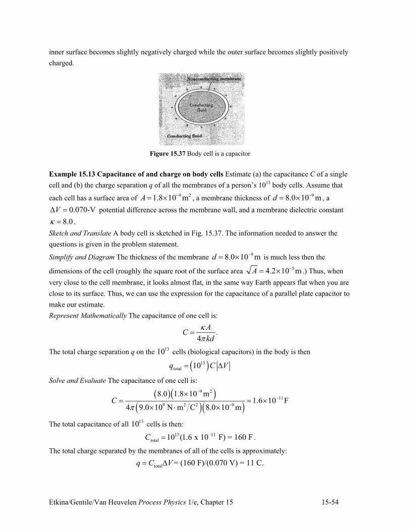
Etkina/Gentile/Van Heuvelen Process Physics 1/e, Chapter 15 15-54
inner surface becomes slightly negatively charged while the outer surface becomes slightly positively
charged.
Figure 15.37 Body cell is a capacitor
Example 15.13 Capacitance of and charge on body cells Estimate (a) the capacitance C of a single
cell and (b) the charge separation q of all the membranes of a person’s 1013 body cells. Assume that
each cell has a surface area of 9 21.8 10 mA +" , , a membrane thickness of
98.0 10 md +" , , a
0.070-VV2 " potential difference across the membrane wall, and a membrane dielectric constant
8.09 " .
Sketch and Translate A body cell is sketched in Fig. 15.37. The information needed to answer the
questions is given in the problem statement.
Simplify and Diagram The thickness of the membrane 98.0 10 md +" , is much less then the
dimensions of the cell (roughly the square root of the surface area 54.2 10 mA +" , .) Thus, when
very close to the cell membrane, it looks almost flat, in the same way Earth appears flat when you are
close to its surface. Thus, we can use the expression for the capacitance of a parallel plate capacitor to
make our estimate.
Represent Mathematically The capacitance of one cell is:
4
AC
kd
9;
" .
The total charge separation q on the 1310 cells (biological capacitors) in the body is then
) *13
total 10q C V" 2
Solve and Evaluate The capacitance of one cell is:
) *) *
) *) *
9 2
11
9 2 2 9
8.0 1.8 10 m1.6 10 F
4 9.0 10 N m C 8.0 10 mC
;
+
+
+
," " ,
, - ,
The total capacitance of all 1310 cells is then:
13 –11
total 10 (1.6 x 10 F) = 160 FC " .
The total charge separated by the membranes of all of the cells is approximately:
total = (160 F)/(0.070 V) = 11 C.q C V" 2
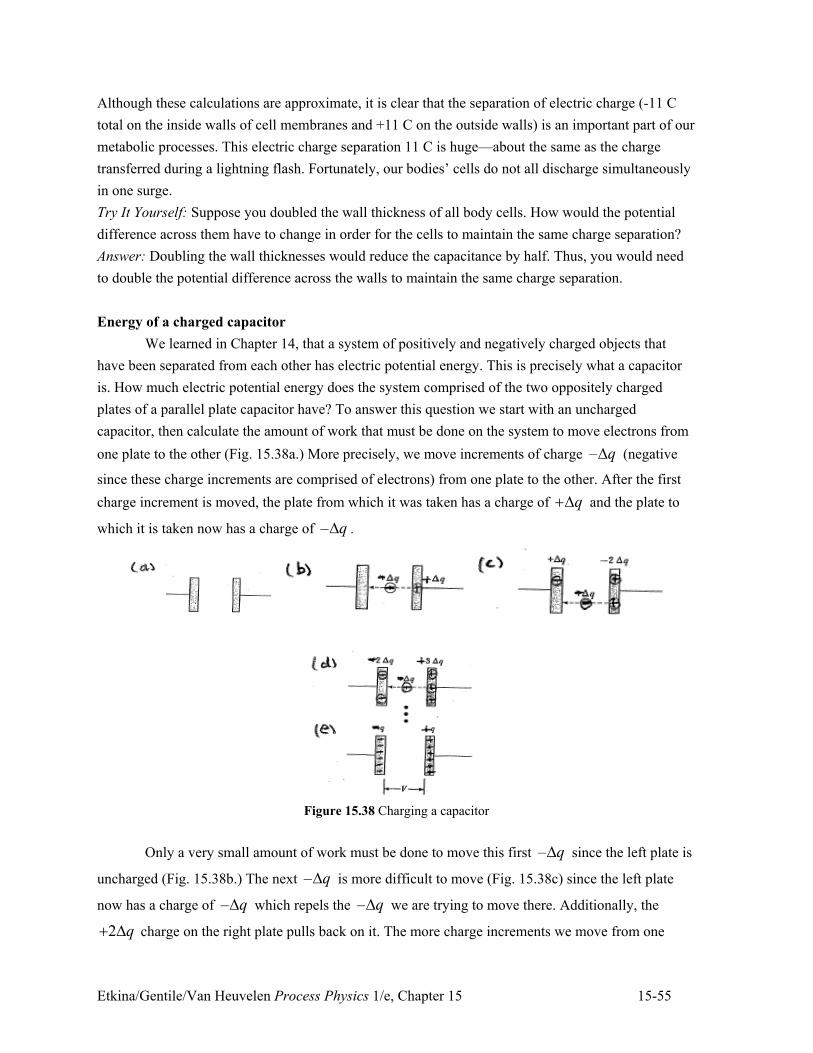
Etkina/Gentile/Van Heuvelen Process Physics 1/e, Chapter 15 15-55
Although these calculations are approximate, it is clear that the separation of electric charge (-11 C
total on the inside walls of cell membranes and +11 C on the outside walls) is an important part of our
metabolic processes. This electric charge separation 11 C is huge—about the same as the charge
transferred during a lightning flash. Fortunately, our bodies’ cells do not all discharge simultaneously
in one surge.
Try It Yourself: Suppose you doubled the wall thickness of all body cells. How would the potential
difference across them have to change in order for the cells to maintain the same charge separation?
Answer: Doubling the wall thicknesses would reduce the capacitance by half. Thus, you would need
to double the potential difference across the walls to maintain the same charge separation.
Energy of a charged capacitor
We learned in Chapter 14, that a system of positively and negatively charged objects that
have been separated from each other has electric potential energy. This is precisely what a capacitor
is. How much electric potential energy does the system comprised of the two oppositely charged
plates of a parallel plate capacitor have? To answer this question we start with an uncharged
capacitor, then calculate the amount of work that must be done on the system to move electrons from
one plate to the other (Fig. 15.38a.) More precisely, we move increments of charge – q2 (negative
since these charge increments are comprised of electrons) from one plate to the other. After the first
charge increment is moved, the plate from which it was taken has a charge of q.2 and the plate to
which it is taken now has a charge of – q2 .
Figure 15.38 Charging a capacitor
Only a very small amount of work must be done to move this first – q2 since the left plate is
uncharged (Fig. 15.38b.) The next – q2 is more difficult to move (Fig. 15.38c) since the left plate
now has a charge of – q2 which repels the – q2 we are trying to move there. Additionally, the
2 q. 2 charge on the right plate pulls back on it. The more charge increments we move from one
Etkina/Gentile/Van Heuvelen Process Physics 1/e, Chapter 15 15-56
plate to the other, the more difficult it becomes to move the next one. Eventually, with increasing
effort, we will have transferred a total (negative) charge of ) * ) *–q q q" +2 . +2 ." to the left plate
leaving the right plate with a charge of +q. We can represent the whole process of charging the
capacitor with a work-energy bar chart (Fig. 15.39). The external object (us, moving the charge
increments) does work on the system (the capacitor) and the electric potential energy of the system
increases.
Figure 15.39 Work done to charge a capacitor
The discussion above was a thought experiment. It’s not possible for us to manually grab
electrons and move them from one capacitor plate to the other. Usually, this external source that does
this work is a battery. The electrical potential energy increase can be calculated using Eq. (15.7):
averageqU q U2 " 2 ,
where averageV2 is the average potential difference from one plate to the other during the process of
charging. Since the initial potential difference is zero and the final is V2 , the average potential
difference between the plates is:
average
0
2 2
V VV
. 2 22 " " .
Substituting this expression for averageV2 into Eq. (15.7), we get:
average2
q
VU q V q
2" 2 " .
The above expression for the electric potential energy of a charged capacitor can be written in three
different ways using Eq. (15.14), q C V" 2 :
221 1 1
2 2 2q
qU q V C V
C" 2 " 2 " . (15.16)
Quantitative Exercise 15.14 Energy needed to charge human body cells In Example 15.15, we
estimated that the total charge separated across all the cell membranes in a human body was about 11
C. Recall that the potential difference across the cell membranes was 0.070 V. Estimate the work that
must be done to separate the charges across the membranes of these approximately 1310 cells. The
situation for one body cell is shown in Fig. 15.37.
Represent Mathematically We can use the first expression in Eq. (15.16) to answer this question:
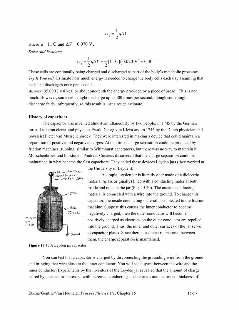
Etkina/Gentile/Van Heuvelen Process Physics 1/e, Chapter 15 15-57
1
2qU q V" 2
where 11 Cq " and 0.070 VV2 " .
Solve and Evaluate
) *) *1 111 C 0.070 V 0.40 J
2 2qU q V" 2 " "
These cells are continually being charged and discharged as part of the body’s metabolic processes.
Try It Yourself: Estimate how much energy is needed to charge the body cells each day assuming that
each cell discharges once per second.
Answer: 35,000 J = 8 kcal or about one-tenth the energy provided by a piece of bread. This is not
much. However, some cells might discharge up to 400 times per second, though some might
discharge fairly infrequently, so this result is just a rough estimate.
History of capacitors
The capacitor was invented almost simultaneously by two people: in 1745 by the German
jurist, Lutheran cleric, and physicist Ewald Georg von Kleist and in 1746 by the Dutch physician and
physicist Pieter van Musschenbroek. They were interested in making a device that could maintain a
separation of positive and negative charges. At that time, charge separation could be produced by
friction machines (rubbing, similar to Whimhurst generators), but there was no way to maintain it.
Musschenbroek and his student Andreas Cunaeus discovered that the charge separation could be
maintained in what became the first capacitors. They called these devices Leyden jars (they worked at
the University of Leyden).
A simple Leyden jar is literally a jar made of a dielectric
material (glass originally) lined with a conducting material both
inside and outside the jar (Fig. 15.40). The outside conducting
material is connected with a wire into the ground. To charge this
capacitor, the inside conducting material is connected to the friction
machine. Suppose this causes the inner conductor to become
negatively charged; then the outer conductor will become
positively charged as electrons on the outer conductor are repelled
into the ground. Thus, the inner and outer surfaces of the jar serve
as capacitor plates. Since there is a dielectric material between
them, the charge separation is maintained.
Figure 15.40 A Leyden jar capacitor
You can test that a capacitor is charged by disconnecting the grounding wire from the ground
and bringing that wire close to the inner conductor. You will see a spark between the wire and the
inner conductor. Experiments by the inventors of the Leyden jar revealed that the amount of charge
stored by a capacitor increased with increased conducting surface areas and decreased thickness of
Etkina/Gentile/Van Heuvelen Process Physics 1/e, Chapter 15 15-58
the dielectric container walls. A typical Leiden jar has a very small capacitance – between
1250 10 F+, and 910 F+
. Contemporary capacitors used routinely in electric circuits have
capacitances on the order of 10-6 F, but 1 F capacitors are now available inexpensively for physics
laboratory experiments.
Energy density of electric field
As we discussed above, the capacitors were invented as devices whose goal was to maintain
charge separation, and therefore store electric potential energy. We found that the energy stored in a
charged capacitor is 21
2qU C V" 2 . Where is this energy stored? One way to answer this is to
notice that the difference between a charged and an uncharged capacitor is the presence of the electric
field in the region between the plates. Perhaps that is where the electric potential energy is stored.
This is a very interesting suggestion, since up until now we have thought of the electric field only as a
mechanism to explain how charged objects can interact without being in physical contact. Suggesting
that the electric field has electric potential energy makes the electric field seem much more real than
just an idea.
Since the electric field fills the region between the plates, we can describe the energy that it
has in terms of an energy density, much in the same way we can characterize an object that fills a
region as having a mass density. This energy density quantifies the electric potential energy stored in
the electric field per cubic meter of volume. Quantitatively, the E!
-field energy density Eu is:
q
E
Uu
V"
where qU is the electric potential energy stored in the E!
-field in that region, and V is the volume of
the region.
Tip! Notice that here the letter V stands for the physical quantity of volume, not for the electric
potential. Sometimes similar or identical symbols are used for different physical quantities. When
looking at a mathematical expression, always ask yourself: “what do each of these symbols
represent?”
The above equation for the electric field energy density is not written in terms of the E!
-field.
Let us rewrite it using our knowledge of the electric energy of a parallel plate capacitor:
) *22 11
2 42q
E
AEdC V
U kdu
V V V
9;
# $# $# $2 % &% &% & ' (' ( ' (" " "
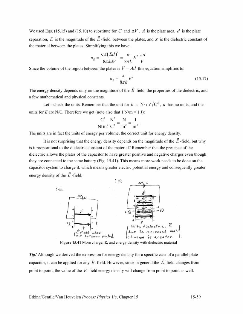
Etkina/Gentile/Van Heuvelen Process Physics 1/e, Chapter 15 15-59
We used Eqs. (15.15) and (15.10) to substitute for C and V2 . A is the plate area, d is the plate
separation, E is the magnitude of the E!
-field between the plates, and 9 is the dielectric constant of
the material between the plates. Simplifying this we have:
) *2
2
8 8E
A Ed Adu E
kdV k V
9 9; ;
" "
Since the volume of the region between the plates is V Ad" this equation simplifies to:
2
8Eu E
k
9;
" (15.17)
The energy density depends only on the magnitude of the E!
field, the properties of the dielectric, and
a few mathematical and physical constants.
Let’s check the units. Remember that the unit for k is 2 2N m C- , 9 has no units, and the
units for E are N/C. Therefore we get (note also that 1 N•m = 1 J):
2 2
2 2 2 3
C N N J
N m C m m" "
�.
The units are in fact the units of energy per volume, the correct unit for energy density.
It is not surprising that the energy density depends on the magnitude of the E!
-field, but why
is it proportional to the dielectric constant of the material? Remember that the presence of the
dielectric allows the plates of the capacitor to have greater positive and negative charges even though
they are connected to the same battery (Fig. 15.41). This means more work needs to be done on the
capacitor system to charge it, which means greater electric potential energy and consequently greater
energy density of the E!
-field.
Figure 15.41 More charge, E, and energy density with dielectric material
Tip! Although we derived the expression for energy density for a specific case of a parallel plate
capacitor, it can be applied for any E!
-field. However, since in general the E!
-field changes from
point to point, the value of the E!
-field energy density will change from point to point as well.
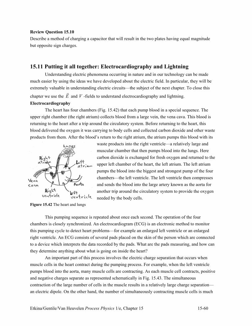
Etkina/Gentile/Van Heuvelen Process Physics 1/e, Chapter 15 15-60
Review Question 15.10
Describe a method of charging a capacitor that will result in the two plates having equal magnitude
but opposite sign charges.
15.11 Putting it all together: Electrocardiography and Lightning
Understanding electric phenomena occurring in nature and in our technology can be made
much easier by using the ideas we have developed about the electric field. In particular, they will be
extremely valuable in understanding electric circuits—the subject of the next chapter. To close this
chapter we use the E!
and V -fields to understand electrocardiography and lightning.
Electrocardiography
The heart has four chambers (Fig. 15.42) that each pump blood in a special sequence. The
upper right chamber (the right atrium) collects blood from a large vein, the vena cava. This blood is
returning to the heart after a trip around the circulatory system. Before returning to the heart, this
blood delivered the oxygen it was carrying to body cells and collected carbon dioxide and other waste
products from them. After the blood’s return to the right atrium, the atrium pumps this blood with its
waste products into the right ventricle—a relatively large and
muscular chamber that then pumps blood into the lungs. Here
carbon dioxide is exchanged for fresh oxygen and returned to the
upper left chamber of the heart, the left atrium. The left atrium
pumps the blood into the biggest and strongest pump of the four
chambers—the left ventricle. The left ventricle then compresses
and sends the blood into the large artery known as the aorta for
another trip around the circulatory system to provide the oxygen
needed by the body cells.
Figure 15.42 The heart and lungs
This pumping sequence is repeated about once each second. The operation of the four
chambers is closely synchronized. An electrocardiogram (ECG) is an electronic method to monitor
this pumping cycle to detect heart problems—for example an enlarged left ventricle or an enlarged
right ventricle. An ECG consists of several pads placed on the skin of the person which are connected
to a device which interprets the data recorded by the pads. What are the pads measuring, and how can
they determine anything about what is going on inside the heart?
An important part of this process involves the electric charge separation that occurs when
muscle cells in the heart contract during the pumping process. For example, when the left ventricle
pumps blood into the aorta, many muscle cells are contracting. As each muscle cell contracts, positive
and negative charges separate as represented schematically in Fig. 15.43. The simultaneous
contraction of the large number of cells in the muscle results in a relatively large charge separation—
an electric dipole. On the other hand, the number of simultaneously contracting muscle cells is much
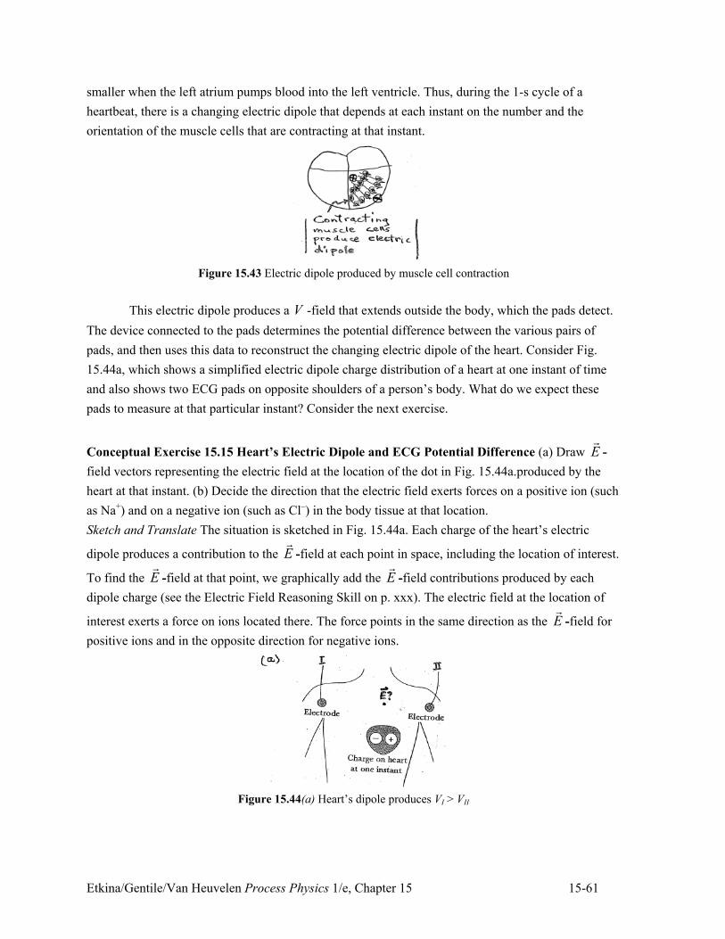
Etkina/Gentile/Van Heuvelen Process Physics 1/e, Chapter 15 15-61
smaller when the left atrium pumps blood into the left ventricle. Thus, during the 1-s cycle of a
heartbeat, there is a changing electric dipole that depends at each instant on the number and the
orientation of the muscle cells that are contracting at that instant.
Figure 15.43 Electric dipole produced by muscle cell contraction
This electric dipole produces a V -field that extends outside the body, which the pads detect.
The device connected to the pads determines the potential difference between the various pairs of
pads, and then uses this data to reconstruct the changing electric dipole of the heart. Consider Fig.
15.44a, which shows a simplified electric dipole charge distribution of a heart at one instant of time
and also shows two ECG pads on opposite shoulders of a person’s body. What do we expect these
pads to measure at that particular instant? Consider the next exercise.
Conceptual Exercise 15.15 Heart’s Electric Dipole and ECG Potential Difference (a) Draw E!
-
field vectors representing the electric field at the location of the dot in Fig. 15.44a.produced by the
heart at that instant. (b) Decide the direction that the electric field exerts forces on a positive ion (such
as Na+) and on a negative ion (such as Cl–) in the body tissue at that location.
Sketch and Translate The situation is sketched in Fig. 15.44a. Each charge of the heart’s electric
dipole produces a contribution to the E!
-field at each point in space, including the location of interest.
To find the E!
-field at that point, we graphically add the E!
-field contributions produced by each
dipole charge (see the Electric Field Reasoning Skill on p. xxx). The electric field at the location of
interest exerts a force on ions located there. The force points in the same direction as the E!
-field for
positive ions and in the opposite direction for negative ions.
Figure 15.44(a) Heart’s dipole produces VI > VII
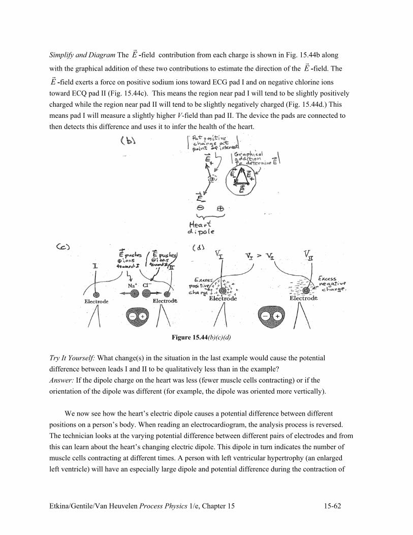
Etkina/Gentile/Van Heuvelen Process Physics 1/e, Chapter 15 15-62
Simplify and Diagram The E!
-field contribution from each charge is shown in Fig. 15.44b along
with the graphical addition of these two contributions to estimate the direction of the E!
-field. The
E!
-field exerts a force on positive sodium ions toward ECG pad I and on negative chlorine ions
toward ECQ pad II (Fig. 15.44c). This means the region near pad I will tend to be slightly positively
charged while the region near pad II will tend to be slightly negatively charged (Fig. 15.44d.) This
means pad I will measure a slightly higher V-field than pad II. The device the pads are connected to
then detects this difference and uses it to infer the health of the heart.
Figure 15.44(b)(c)(d)
Try It Yourself: What change(s) in the situation in the last example would cause the potential
difference between leads I and II to be qualitatively less than in the example?
Answer: If the dipole charge on the heart was less (fewer muscle cells contracting) or if the
orientation of the dipole was different (for example, the dipole was oriented more vertically).
We now see how the heart’s electric dipole causes a potential difference between different
positions on a person’s body. When reading an electrocardiogram, the analysis process is reversed.
The technician looks at the varying potential difference between different pairs of electrodes and from
this can learn about the heart’s changing electric dipole. This dipole in turn indicates the number of
muscle cells contracting at different times. A person with left ventricular hypertrophy (an enlarged
left ventricle) will have an especially large dipole and potential difference during the contraction of
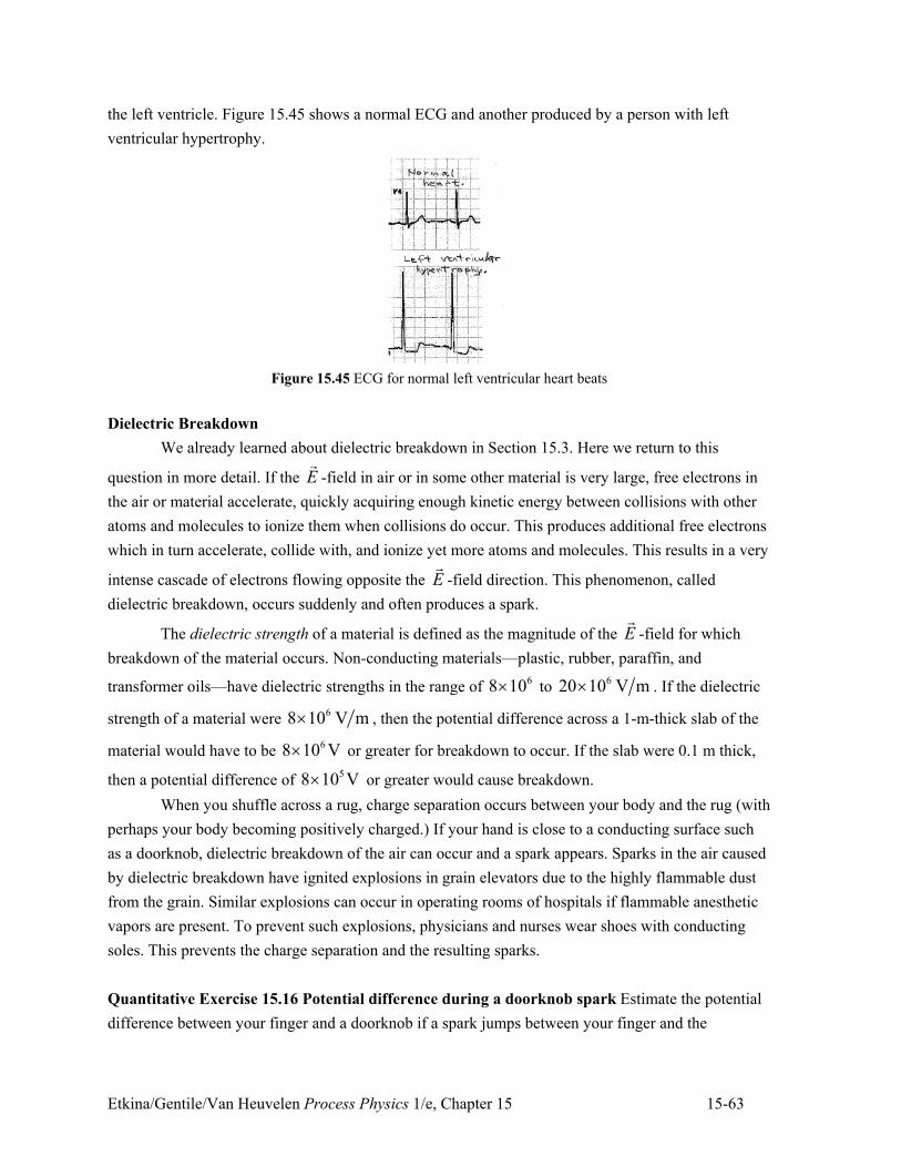
Etkina/Gentile/Van Heuvelen Process Physics 1/e, Chapter 15 15-63
the left ventricle. Figure 15.45 shows a normal ECG and another produced by a person with left
ventricular hypertrophy.
Figure 15.45 ECG for normal left ventricular heart beats
Dielectric Breakdown
We already learned about dielectric breakdown in Section 15.3. Here we return to this
question in more detail. If the E!
-field in air or in some other material is very large, free electrons in
the air or material accelerate, quickly acquiring enough kinetic energy between collisions with other
atoms and molecules to ionize them when collisions do occur. This produces additional free electrons
which in turn accelerate, collide with, and ionize yet more atoms and molecules. This results in a very
intense cascade of electrons flowing opposite the E!
-field direction. This phenomenon, called
dielectric breakdown, occurs suddenly and often produces a spark.
The dielectric strength of a material is defined as the magnitude of the E!
-field for which
breakdown of the material occurs. Non-conducting materials—plastic, rubber, paraffin, and
transformer oils—have dielectric strengths in the range of 68 10, to
620 10 V m, . If the dielectric
strength of a material were 68 10 V m, , then the potential difference across a 1-m-thick slab of the
material would have to be 68 10 V, or greater for breakdown to occur. If the slab were 0.1 m thick,
then a potential difference of 58 10 V, or greater would cause breakdown.
When you shuffle across a rug, charge separation occurs between your body and the rug (with
perhaps your body becoming positively charged.) If your hand is close to a conducting surface such
as a doorknob, dielectric breakdown of the air can occur and a spark appears. Sparks in the air caused
by dielectric breakdown have ignited explosions in grain elevators due to the highly flammable dust
from the grain. Similar explosions can occur in operating rooms of hospitals if flammable anesthetic
vapors are present. To prevent such explosions, physicians and nurses wear shoes with conducting
soles. This prevents the charge separation and the resulting sparks.
Quantitative Exercise 15.16 Potential difference during a doorknob spark Estimate the potential
difference between your finger and a doorknob if a spark jumps between your finger and the
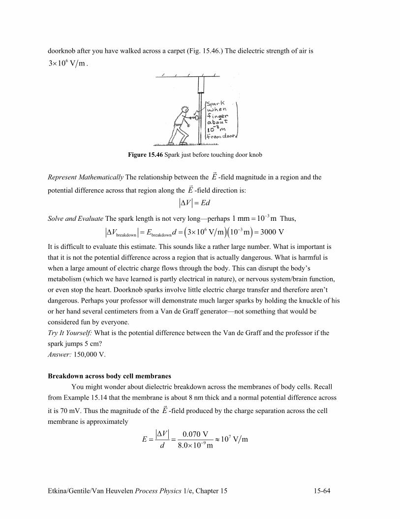
Etkina/Gentile/Van Heuvelen Process Physics 1/e, Chapter 15 15-64
doorknob after you have walked across a carpet (Fig. 15.46.) The dielectric strength of air is
63 10 V m, .
Figure 15.46 Spark just before touching door knob
Represent Mathematically The relationship between the E!
-field magnitude in a region and the
potential difference across that region along the E!
-field direction is:
V Ed2 "
Solve and Evaluate The spark length is not very long—perhaps 31 mm 10 m+" Thus,
) *) *6 3
breakdown breakdown 3 10 V m 10 m 3000 VV E d +2 " " , "
It is difficult to evaluate this estimate. This sounds like a rather large number. What is important is
that it is not the potential difference across a region that is actually dangerous. What is harmful is
when a large amount of electric charge flows through the body. This can disrupt the body’s
metabolism (which we have learned is partly electrical in nature), or nervous system/brain function,
or even stop the heart. Doorknob sparks involve little electric charge transfer and therefore aren’t
dangerous. Perhaps your professor will demonstrate much larger sparks by holding the knuckle of his
or her hand several centimeters from a Van de Graff generator—not something that would be
considered fun by everyone.
Try It Yourself: What is the potential difference between the Van de Graff and the professor if the
spark jumps 5 cm?
Answer: 150,000 V.
Breakdown across body cell membranes
You might wonder about dielectric breakdown across the membranes of body cells. Recall
from Example 15.14 that the membrane is about 8 nm thick and a normal potential difference across
it is 70 mV. Thus the magnitude of the E!
-field produced by the charge separation across the cell
membrane is approximately
7
9
0.070 V10 V m
8.0 10 m
VE
d +
2" " 8
,
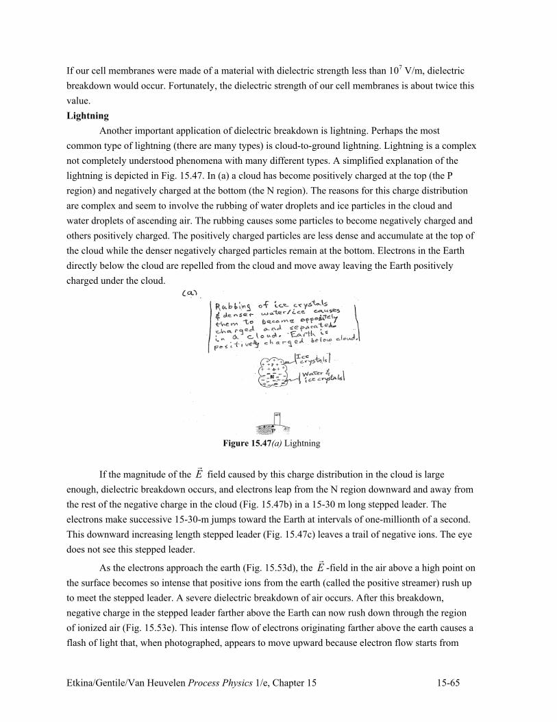
Etkina/Gentile/Van Heuvelen Process Physics 1/e, Chapter 15 15-65
If our cell membranes were made of a material with dielectric strength less than 107 V/m, dielectric
breakdown would occur. Fortunately, the dielectric strength of our cell membranes is about twice this
value.
Lightning
Another important application of dielectric breakdown is lightning. Perhaps the most
common type of lightning (there are many types) is cloud-to-ground lightning. Lightning is a complex
not completely understood phenomena with many different types. A simplified explanation of the
lightning is depicted in Fig. 15.47. In (a) a cloud has become positively charged at the top (the P
region) and negatively charged at the bottom (the N region). The reasons for this charge distribution
are complex and seem to involve the rubbing of water droplets and ice particles in the cloud and
water droplets of ascending air. The rubbing causes some particles to become negatively charged and
others positively charged. The positively charged particles are less dense and accumulate at the top of
the cloud while the denser negatively charged particles remain at the bottom. Electrons in the Earth
directly below the cloud are repelled from the cloud and move away leaving the Earth positively
charged under the cloud.
Figure 15.47(a) Lightning
If the magnitude of the E!
field caused by this charge distribution in the cloud is large
enough, dielectric breakdown occurs, and electrons leap from the N region downward and away from
the rest of the negative charge in the cloud (Fig. 15.47b) in a 15-30 m long stepped leader. The
electrons make successive 15-30-m jumps toward the Earth at intervals of one-millionth of a second.
This downward increasing length stepped leader (Fig. 15.47c) leaves a trail of negative ions. The eye
does not see this stepped leader.
As the electrons approach the earth (Fig. 15.53d), the E!
-field in the air above a high point on
the surface becomes so intense that positive ions from the earth (called the positive streamer) rush up
to meet the stepped leader. A severe dielectric breakdown of air occurs. After this breakdown,
negative charge in the stepped leader farther above the Earth can now rush down through the region
of ionized air (Fig. 15.53e). This intense flow of electrons originating farther above the earth causes a
flash of light that, when photographed, appears to move upward because electron flow starts from
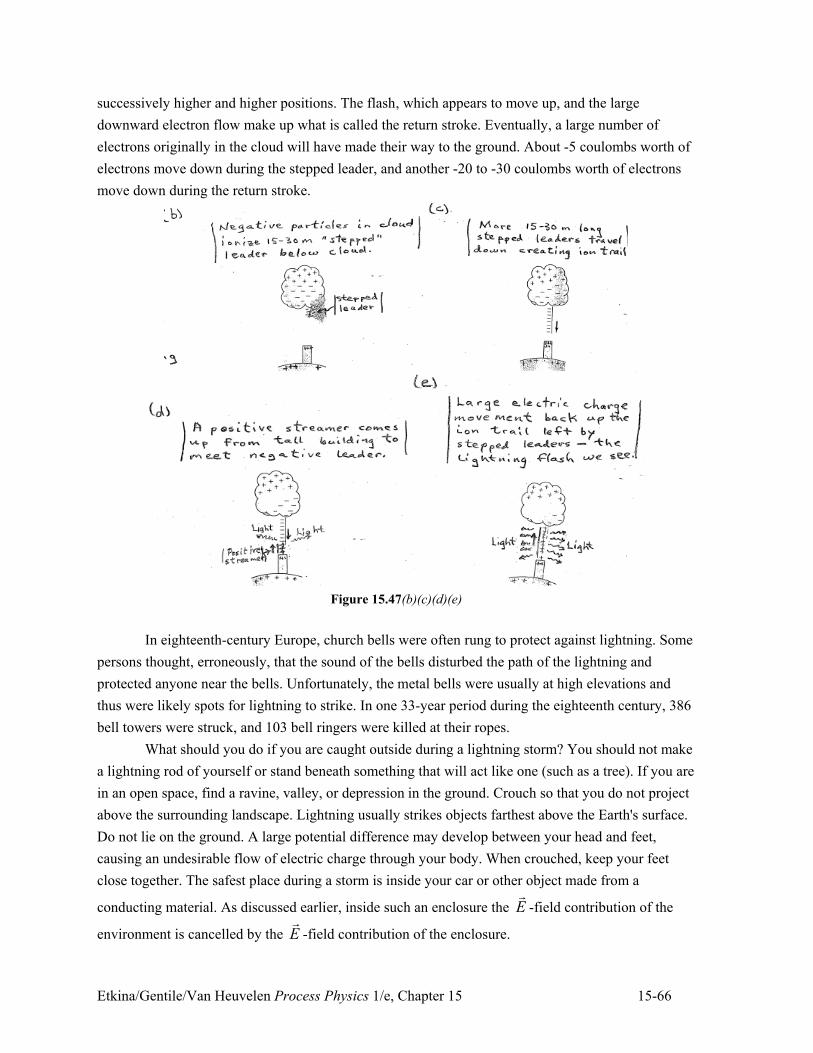
Etkina/Gentile/Van Heuvelen Process Physics 1/e, Chapter 15 15-66
successively higher and higher positions. The flash, which appears to move up, and the large
downward electron flow make up what is called the return stroke. Eventually, a large number of
electrons originally in the cloud will have made their way to the ground. About -5 coulombs worth of
electrons move down during the stepped leader, and another -20 to -30 coulombs worth of electrons
move down during the return stroke.
Figure 15.47(b)(c)(d)(e)
In eighteenth-century Europe, church bells were often rung to protect against lightning. Some
persons thought, erroneously, that the sound of the bells disturbed the path of the lightning and
protected anyone near the bells. Unfortunately, the metal bells were usually at high elevations and
thus were likely spots for lightning to strike. In one 33-year period during the eighteenth century, 386
bell towers were struck, and 103 bell ringers were killed at their ropes.
What should you do if you are caught outside during a lightning storm? You should not make
a lightning rod of yourself or stand beneath something that will act like one (such as a tree). If you are
in an open space, find a ravine, valley, or depression in the ground. Crouch so that you do not project
above the surrounding landscape. Lightning usually strikes objects farthest above the Earth's surface.
Do not lie on the ground. A large potential difference may develop between your head and feet,
causing an undesirable flow of electric charge through your body. When crouched, keep your feet
close together. The safest place during a storm is inside your car or other object made from a
conducting material. As discussed earlier, inside such an enclosure the E!
-field contribution of the
environment is cancelled by the E!
-field contribution of the enclosure.
Etkina/Gentile/Van Heuvelen Process Physics 1/e, Chapter 15 15-67
Review Question 15.11
How do ECG pads attached to a person’s shoulders let doctors learn about the heart deep inside the
chest of a patient?
Summary
Word Representation Picture and
Diagram
Representation
Mathematical
Representation
E!
-Field is a physical quantity characterizing electric
field at a point. The E!
-field at a point is determined
by imagining a pointlike positively charged object
Oq (the system) located at that point. The E
!-field
equals the net electric force exerted by other charged
objects on O
q divided by that object’s charge. The
units of E!
-field are newtons/coulomb (N/C). The
E!
-field exerts a force on a charged object in the
field.
O
O
other on Q qFE
q"
!
! (15.2)
Field on O O= F q E
##! ##! (15.4)
Superposition principle When n charged objects
contribute to the E!
-field at a point, the E!
-field is
the vector sum of those contributions.
1 2 3E E E E" . . .! ! ! !
" (15.5)
V-field is another physical quantity characterizing
electric field at a point. To determine its value,
imagine a positively charged pointlike object oq at a
position of interest. The V -field (electric potential)
at that position is the electric potential energy qU of
that object and all other charged charges divided by
the charge of that object. Include the signs of
charges when calculating qU . The unit of electric
potential is the volt (V) where 1 V = 1 J/C
(joule/coulomb). If know V at a point, then can find
qU at that point.
O
qUV
q" (15.6)
where
1 o 2 o
1 to O 2 to O
+ + ...q
UkQ q kQ q
r r"
q qVU " (15.7)
Superposition principle for V -field When n charged
objects contribute to the V -field at a point, the V -
field is the vector sum of those contributions.
1 2 3V V V V" . . ." (15.9)
E!
-field and V field are related The greater the
magnitude of the E!
-field at a particular location, the
faster the V -field changes with position near that
location.
!V = –Ex !x (15.10)
or
2 11 to 2
2 1
––
–x
V VE
x x" (15.11)
Representing the E!
field and the V field E!
-field
lines that start on positive charges and end on
negative charges represent the E!
-field. Lines on the
Related Documents


